EP2648307A1 - Dispositif de marche automatique, poste de charge, système de connexion et procédé de connexion - Google Patents
Dispositif de marche automatique, poste de charge, système de connexion et procédé de connexion Download PDFInfo
- Publication number
- EP2648307A1 EP2648307A1 EP11844275.5A EP11844275A EP2648307A1 EP 2648307 A1 EP2648307 A1 EP 2648307A1 EP 11844275 A EP11844275 A EP 11844275A EP 2648307 A1 EP2648307 A1 EP 2648307A1
- Authority
- EP
- European Patent Office
- Prior art keywords
- signal
- docking
- robot
- conductive terminal
- control unit
- Prior art date
- Legal status (The legal status is an assumption and is not a legal conclusion. Google has not performed a legal analysis and makes no representation as to the accuracy of the status listed.)
- Granted
Links
- 238000003032 molecular docking Methods 0.000 title claims abstract description 780
- 238000000034 method Methods 0.000 title claims abstract description 96
- 238000001514 detection method Methods 0.000 claims abstract description 296
- 238000003860 storage Methods 0.000 claims abstract description 105
- 230000008054 signal transmission Effects 0.000 claims abstract description 72
- 230000008569 process Effects 0.000 claims description 65
- 238000012546 transfer Methods 0.000 claims description 38
- 230000007423 decrease Effects 0.000 claims description 19
- 230000008859 change Effects 0.000 claims description 14
- 238000005520 cutting process Methods 0.000 claims description 12
- 241001494496 Leersia Species 0.000 claims description 7
- 230000000977 initiatory effect Effects 0.000 claims description 4
- 230000007704 transition Effects 0.000 claims 39
- 238000004519 manufacturing process Methods 0.000 abstract description 2
- 238000006243 chemical reaction Methods 0.000 description 141
- 101100236764 Caenorhabditis elegans mcu-1 gene Proteins 0.000 description 74
- 230000005540 biological transmission Effects 0.000 description 37
- 230000003287 optical effect Effects 0.000 description 22
- 238000012795 verification Methods 0.000 description 11
- 230000006378 damage Effects 0.000 description 9
- 208000027418 Wounds and injury Diseases 0.000 description 5
- 208000014674 injury Diseases 0.000 description 5
- 239000002184 metal Substances 0.000 description 5
- 239000002253 acid Substances 0.000 description 4
- 238000004891 communication Methods 0.000 description 4
- 230000007246 mechanism Effects 0.000 description 4
- 230000008901 benefit Effects 0.000 description 3
- 238000004364 calculation method Methods 0.000 description 3
- 238000007599 discharging Methods 0.000 description 3
- 230000003321 amplification Effects 0.000 description 2
- 230000003247 decreasing effect Effects 0.000 description 2
- 238000010586 diagram Methods 0.000 description 2
- 239000000428 dust Substances 0.000 description 2
- 238000003199 nucleic acid amplification method Methods 0.000 description 2
- 230000009467 reduction Effects 0.000 description 2
- 230000009286 beneficial effect Effects 0.000 description 1
- 230000007547 defect Effects 0.000 description 1
- 238000011161 development Methods 0.000 description 1
- 238000005516 engineering process Methods 0.000 description 1
- 238000010438 heat treatment Methods 0.000 description 1
- 238000009776 industrial production Methods 0.000 description 1
- 238000002955 isolation Methods 0.000 description 1
- 239000000047 product Substances 0.000 description 1
- 238000005728 strengthening Methods 0.000 description 1
- 239000000126 substance Substances 0.000 description 1
- 239000013589 supplement Substances 0.000 description 1
- 230000009469 supplementation Effects 0.000 description 1
Images


Classifications
-
- A—HUMAN NECESSITIES
- A47—FURNITURE; DOMESTIC ARTICLES OR APPLIANCES; COFFEE MILLS; SPICE MILLS; SUCTION CLEANERS IN GENERAL
- A47L—DOMESTIC WASHING OR CLEANING; SUCTION CLEANERS IN GENERAL
- A47L9/00—Details or accessories of suction cleaners, e.g. mechanical means for controlling the suction or for effecting pulsating action; Storing devices specially adapted to suction cleaners or parts thereof; Carrying-vehicles specially adapted for suction cleaners
- A47L9/28—Installation of the electric equipment, e.g. adaptation or attachment to the suction cleaner; Controlling suction cleaners by electric means
- A47L9/2805—Parameters or conditions being sensed
-
- G—PHYSICS
- G05—CONTROLLING; REGULATING
- G05D—SYSTEMS FOR CONTROLLING OR REGULATING NON-ELECTRIC VARIABLES
- G05D1/00—Control of position, course, altitude or attitude of land, water, air or space vehicles, e.g. using automatic pilots
- G05D1/02—Control of position or course in two dimensions
- G05D1/021—Control of position or course in two dimensions specially adapted to land vehicles
- G05D1/0212—Control of position or course in two dimensions specially adapted to land vehicles with means for defining a desired trajectory
- G05D1/0225—Control of position or course in two dimensions specially adapted to land vehicles with means for defining a desired trajectory involving docking at a fixed facility, e.g. base station or loading bay
-
- G—PHYSICS
- G05—CONTROLLING; REGULATING
- G05D—SYSTEMS FOR CONTROLLING OR REGULATING NON-ELECTRIC VARIABLES
- G05D1/00—Control of position, course, altitude or attitude of land, water, air or space vehicles, e.g. using automatic pilots
- G05D1/02—Control of position or course in two dimensions
- G05D1/021—Control of position or course in two dimensions specially adapted to land vehicles
- G05D1/0259—Control of position or course in two dimensions specially adapted to land vehicles using magnetic or electromagnetic means
- G05D1/0265—Control of position or course in two dimensions specially adapted to land vehicles using magnetic or electromagnetic means using buried wires
-
- H—ELECTRICITY
- H02—GENERATION; CONVERSION OR DISTRIBUTION OF ELECTRIC POWER
- H02J—CIRCUIT ARRANGEMENTS OR SYSTEMS FOR SUPPLYING OR DISTRIBUTING ELECTRIC POWER; SYSTEMS FOR STORING ELECTRIC ENERGY
- H02J7/00—Circuit arrangements for charging or depolarising batteries or for supplying loads from batteries
- H02J7/00032—Circuit arrangements for charging or depolarising batteries or for supplying loads from batteries characterised by data exchange
- H02J7/00036—Charger exchanging data with battery
-
- H—ELECTRICITY
- H02—GENERATION; CONVERSION OR DISTRIBUTION OF ELECTRIC POWER
- H02J—CIRCUIT ARRANGEMENTS OR SYSTEMS FOR SUPPLYING OR DISTRIBUTING ELECTRIC POWER; SYSTEMS FOR STORING ELECTRIC ENERGY
- H02J7/00—Circuit arrangements for charging or depolarising batteries or for supplying loads from batteries
- H02J7/00047—Circuit arrangements for charging or depolarising batteries or for supplying loads from batteries with provisions for charging different types of batteries
-
- H—ELECTRICITY
- H02—GENERATION; CONVERSION OR DISTRIBUTION OF ELECTRIC POWER
- H02J—CIRCUIT ARRANGEMENTS OR SYSTEMS FOR SUPPLYING OR DISTRIBUTING ELECTRIC POWER; SYSTEMS FOR STORING ELECTRIC ENERGY
- H02J7/00—Circuit arrangements for charging or depolarising batteries or for supplying loads from batteries
- H02J7/0029—Circuit arrangements for charging or depolarising batteries or for supplying loads from batteries with safety or protection devices or circuits
- H02J7/0036—Circuit arrangements for charging or depolarising batteries or for supplying loads from batteries with safety or protection devices or circuits using connection detecting circuits
-
- A—HUMAN NECESSITIES
- A47—FURNITURE; DOMESTIC ARTICLES OR APPLIANCES; COFFEE MILLS; SPICE MILLS; SUCTION CLEANERS IN GENERAL
- A47L—DOMESTIC WASHING OR CLEANING; SUCTION CLEANERS IN GENERAL
- A47L2201/00—Robotic cleaning machines, i.e. with automatic control of the travelling movement or the cleaning operation
- A47L2201/02—Docking stations; Docking operations
- A47L2201/022—Recharging of batteries
Definitions
- the invention relates to a robot.
- the invention also relates to a docking station.
- the invention also relates to a docking system comprising a robot and a docking station.
- the invention also relates to a method for automatic docking of a robot and a docking station.
- the robots can implement the related predetermined tasks without manual operation and interference according to the predetermined programs, and therefore are widely applied to industrial and household products; such as robots conducting various functions, lawn movers, and dust collectors.
- the intelligent robots greatly save time for people and bring great convenience to industrial production and household living.
- Those robots adopt a power storage unit to supply power, but when the power in the power storage unit is exhausted, they cannot work. At this moment, people have to move the robots to the docking station to supplement power. In some circumstances, power supplementation may cost several hours, so people have to wait for several hours before re-starting the robots and having it work continuously.
- the present invention provides a docking system for a robot to docking to a docking station.
- the docking system comprises a robot and a docking station.
- the robot comprises a power storage unit configured to supply power for the robot, a docking terminal group comprising at least a first docking terminal and a second docking terminal, and a robot control unit configured to control working state of the robot.
- the docking station comprises a conductive terminal group comprising at least a first conductive terminal and a second conductive terminal.
- the conductive terminal group is configured to be electrically connected to the docking terminal group respectively.
- the robot control unit comprises a signal transmission module configured to be electrically connected to the first docking terminal and send a predetermined detection signal, a signal receiving module configured to be electrically connected to the second docking terminal. When the signal receiving module receives a predetermined feedback signal corresponding to the predetermined detection signal, the robot control unit verifies that the docking of the docking terminal group of the robot with the conductive terminal group of the docking station has
- the predetermined detection signal and the predetermined feedback signal are regular variable signals.
- the predetermined detection signal and the predetermined feedback signal have same period.
- the predetermined detection signal and the predetermined feedback signal are square wave signals and have same period.
- the robot also includes at least one of a first signal conversion unit and a second signal conversion unit, the first signal conversion unit is set between the signal transmission module and the first docking terminal, the second signal conversion unit is set between the signal receiving module and the second docking terminal, the first signal conversion unit and the second signal conversion unit can change electrical parameters of signal passing therethrough.
- the first signal conversion unit and the second signal conversion unit amplify or decrease the signals passing therethrough.
- the robot includes the first signal conversion unit and the second signal conversion unit, the first signal conversion unit amplifies the signal passing therethrough, the second signal conversion unit decreases the signal passing therethrough.
- the second signal conversion unit isolates electrical signal transferred between the second docking terminal and the signal receiving module.
- the robot control unit controls robot stopping moving.
- the signal transmission module sends a predetermined detection signal again, if the signal receiving module receives a predetermined feedback signal corresponding to the predetermined detection signal, the robot control unit controls the robot keeping the status of stopping moving, if the signal receiving module does not receive a predetermined feedback signal corresponding to the predetermined detection signal, the robot control unit controls the robot beginning to move.
- the docking station also includes an across circuit set between the first conductive terminal and the second conductive terminal, the across circuit transfers signal between the first conductive terminal and the second conductive terminal.
- the docking station also includes a docking station control unit, the docking station control unit controls working state of the docking station and detects signal transferred between the first conductive terminal and the second conductive terminal, when docking station control unit detects a predetermined startup signal corresponding to the predetermined detection signal, docking station control unit controls docking station to begin charging process.
- the predetermined startup signal is a regular variable square wave signal.
- the predetermined startup signal is a square wave having a predetermined period.
- the docking station also includes a signal detection unit which is set between the docking station control unit and the first and second conductive terminals, the docking station control unit detects signal transferred between the first conductive terminal and the second conductive terminal through the signal detection unit.
- the signal detection unit changes electrical parameters of signal passing therethrough.
- the signal detection unit decreases the signal passing therethrough.
- the signal detection unit isolates electrical signal transferred between the conductive terminal group and docking station control unit.
- the docking station also includes an output power control unit which permits or prevents providing charging power to the first conductive terminal and the second conductive terminal, before beginning charging process, the docking station control unit controls the output power control unit preventing providing charging power to the first conductive terminal and the second conductive terminal, the output power of the first conductive terminal and the second conductive terminal is zero, after beginning charging process, the docking station control unit controls the output power control unit permitting providing charging power to the first conductive terminal and the second conductive terminal, the first conductive terminal and the second conductive terminal output the charging power.
- an output power control unit which permits or prevents providing charging power to the first conductive terminal and the second conductive terminal, before beginning charging process, the docking station control unit controls the output power control unit preventing providing charging power to the first conductive terminal and the second conductive terminal, the output power of the first conductive terminal and the second conductive terminal is zero, after beginning charging process, the docking station control unit controls the output power control unit permitting providing charging power to the first conductive terminal and the second conductive terminal, the first conductive
- the robot also includes a storage power detection unit which detects power level of the power storage unit and transfers the detected signal to the robot control unit, when the power level is less than a predetermined level, the robot control unit controls the robot returning to the docking station.
- a storage power detection unit which detects power level of the power storage unit and transfers the detected signal to the robot control unit, when the power level is less than a predetermined level, the robot control unit controls the robot returning to the docking station.
- the robot also includes a forced charging assembly which operatively sends a charging order signal to the robot control unit, when the forced charging assembly sends a charging order signal, the robot control unit controls the robot returning to the docking station.
- a forced charging assembly which operatively sends a charging order signal to the robot control unit, when the forced charging assembly sends a charging order signal, the robot control unit controls the robot returning to the docking station.
- the robot also includes a rain detector which sends a detected signal to the robot control unit, when the rain detector detects rain, the robot control unit controls the robot returning to the docking station.
- a rain detector which sends a detected signal to the robot control unit, when the rain detector detects rain, the robot control unit controls the robot returning to the docking station.
- the docking system also includes a boundary wire, the docking station electrically connects with the boundary wire, the robot goes along the boundary wire to return to the docking station.
- the robot is a lawn mower and includes a cutting assembly operable to cut grass.
- the present invention also provides another docking system comprising a robot and a docking station.
- the robot comprises a docking terminal group comprising at least a first docking terminal and a second docking terminal.
- the docking station comprises a conductive terminal group comprising at least a first conductive terminal and a second conductive terminal, the conductive terminal group configured to be electrically connected to the docking terminal group respectively.
- the robot also comprises a signal transmission module configured to be electrically connected to the first docking terminal and send out a predetermined detection signal through the first docking terminal; a signal receiving module configured to receive signal from the second docking terminal.
- the signal receiving module receives a predetermined feedback signal corresponding to the predetermined detection signal, the robot verifies that the docking of the docking terminal group of the robot with the conductive terminal group of the docking station has succeeded.
- the predetermined detection signal and the predetermined feedback signal are regular variable signals.
- the predetermined detection signal and the predetermined feedback signal have same period.
- the predetermined detection signal and the predetermined feedback signal are square wave signals and have same period.
- the present invention also provides another docking system comprising a robot and a docking station.
- the robot comprises a docking terminal group comprising at least a first docking terminal and a second docking terminal.
- the docking station comprises a conductive terminal group which comprises at least a first conductive terminal and a second conductive terminal, the conductive terminal group configured to be electrically connected to the docking terminal group respectively.
- the robot sends out a predetermined detection signal through the first docking terminal and receives signal from the second docking terminal.
- the robot receives a predetermined feedback signal corresponding to the predetermined detection signal, the robot verifies that the docking of the docking terminal group of the robot with the conductive terminal group of the docking station has succeeded.
- the predetermined detection signal and the predetermined feedback signal are regular variable signals.
- the predetermined detection signal and the predetermined feedback signal have same period.
- the predetermined detection signal and the predetermined feedback signal are square wave signals and have same period.
- the present invention also provides a docking method for docking a robot to a docking station.
- the robot comprises a docking terminal group and a robot control unit.
- the docking terminal group comprises at least a first docking terminal and a second docking terminal.
- the robot control unit comprises a signal transmission module configured to be electrically connected to the first docking terminal and a signal receiving module configured to be electrically connected to the second docking terminal.
- the docking station comprises a conductive terminal group.
- the conductive terminal group comprises at least a first conductive terminal and a second conductive terminal.
- the conductive terminal group is configured to be electrically connected to the docking terminal group respectively.
- the docking method comprises the steps of the signal transmission module sending out a predetermined detection signal; determining if the signal receiving module has received a predetermined feedback signal corresponding to the predetermined detection signal; when the signal receiving module has received a predetermined feedback signal corresponding to the predetermined detection signal, verifying that the docking of the docking terminal group in the robot with the conductive terminal group in the docking station has succeeded.
- the predetermined detection signal and the predetermined feedback signal are regular variable signals.
- the predetermined detection signal and the predetermined feedback signal have same period.
- the predetermined detection signal and the predetermined feedback signal are square wave signals and have same period.
- At least one of a first signal conversion unit and a second signal conversion unit is set in the robot, the first signal conversion unit is set between the signal transmission module and the first docking terminal, the second signal conversion unit is set between the signal receiving module and the second docking terminal, the first signal conversion unit and the second signal conversion unit can change electrical parameters of signal passing therethrough.
- the first signal conversion unit and the second signal conversion unit amplify or decrease the signals passing therethrough.
- the first signal conversion unit and the second signal conversion unit are set in the robot, the first signal conversion unit amplifies the signal passing therethrough, the second signal conversion unit decreases the signal passing therethrough.
- the second signal conversion unit isolates electrical signal transferred between the second docking terminal and the signal receiving module.
- the robot stops moving.
- the signal transmission module sends out a predetermined detection signal again, if the signal receiving module receives a predetermined feedback signal corresponding to the predetermined detection signal, the robot control unit controls the robot keeping the status of stopping moving, if the signal receiving module does not receive a predetermined feedback signal corresponding to the predetermined detection signal, the robot control unit controls the robot beginning to move.
- an across circuit is set between the first conductive terminal and the second conductive terminal, the across circuit transfers signal between the first conductive terminal and the second conductive terminal.
- a docking station control unit is set in the docking station, the docking station control unit controls working state of the docking station and detects signal transferred between the first conductive terminal and the second conductive terminal, when docking station control unit detects a predetermined startup signal corresponding to the predetermined detection signal, the docking station control unit controls docking station to begin charging process.
- the predetermined startup signal is a regular variable square wave signal.
- the predetermined startup signal is a square wave signal having a predetermined period.
- a signal detection unit is set between the docking station control unit and the first and second conductive terminals, the docking station control unit detects signal transferred between the first conductive terminal and the second conductive terminal through the signal detection unit.
- the signal detection unit changes electrical parameters of signal passing therethrough.
- the signal detection unit decreases the signal passing therethrough.
- the signal detection unit isolates electrical signal transferred between the conductive terminal group and the docking station control unit.
- an output power control unit is set in the docking station, the output power control permits or prevents providing charging power to the first conductive terminal and the second conductive terminal, before beginning charging process, the docking station control unit controls the output power control unit preventing providing charging power to the first conductive terminal and the second conductive terminal, the output power of the first conductive terminal and the second conductive terminal is zero, after beginning charging process, the docking station control unit controls the output power control unit permitting providing charging power to the first conductive terminal and the second conductive terminal, the first conductive terminal and the second conductive terminal output the charging power.
- a storage power detection unit is set in the robot, the storage power detection unit detects power level of the power storage unit and transfers the detected signal to the robot control unit, when the power level is less than a predetermined level, the robot control unit controls the robot returning to the docking station.
- the robot also includes a forced charging assembly which operatively sends a charging order signal to the robot control unit, when the forced charging assembly sends a charging order signal, the robot control unit controls the robot returning to the docking station.
- a forced charging assembly which operatively sends a charging order signal to the robot control unit, when the forced charging assembly sends a charging order signal, the robot control unit controls the robot returning to the docking station.
- the robot also includes a rain detector which sends out a detected signal to the robot control unit, when the rain detector detects rain, the robot control unit controls the robot returning to the docking station.
- a rain detector which sends out a detected signal to the robot control unit, when the rain detector detects rain, the robot control unit controls the robot returning to the docking station.
- the robot is a lawn mower and includes a cutting assembly operable to cut grass.
- the present invention also provides a robot which can selectively dock to a docking station and receive charging power from the docking station.
- the robot comprises a docking terminal group.
- the docking terminal group comprises at least a first docking terminal and a second docking terminal.
- the docking station comprises a conductive terminal group which comprises at least a first conductive terminal and a second conductive terminal.
- the conductive terminal group is configured to be electrically connected to the docking terminal group respectively.
- the robot also comprises a power storage unit configured to supply power for the robot; a robot control unit configured to control working state of the robot.
- the robot control unit comprises a signal transmission module configured to be electrically connected to the first docking terminal and send out a predetermined detection signal; a signal receiving module configured to be electrically connected to the second docking terminal.
- the signal receiving module receives a predetermined feedback signal corresponding to the predetermined detection signal
- the robot control unit verifies that the docking of the docking terminal group of the robot with the conductive terminal group of the
- the predetermined detection signal and the predetermined feedback signal are regular variable signals.
- the predetermined detection signal and the predetermined feedback signal have same period.
- the predetermined detection signal and the predetermined feedback signal are square wave signals and have same period.
- the robot includes at least one of a first signal conversion unit and a second signal conversion unit, the first signal conversion unit is set between the signal transmission module and the first docking terminal, the second signal conversion unit is set between the signal receiving module and the second docking terminal, the first signal conversion unit and the second signal conversion unit can change electrical parameters of signal passing therethrough.
- the first signal conversion unit and the second signal conversion unit amplify or decrease the signals passing therethrough.
- the robot includes the first signal conversion unit and the second signal conversion unit, the first signal conversion unit amplifies the signal passing therethrough, the second signal conversion unit decreases the signal passing therethrough.
- the second signal conversion unit isolates electrical signal transferred between the second docking terminal and the signal receiving module.
- the robot control unit controls robot stopping moving.
- the signal transmission module sends out a predetermined detection signal, if the signal receiving module receives a predetermined feedback signal corresponding to the predetermined detection signal, the robot control unit controls the robot keeping the status of stopping moving, if the signal receiving module does not receive a predetermined feedback signal corresponding to the predetermined detection signal, the robot control unit controls the robot beginning to move.
- the robot also includes a storage power detection unit which detects power level of the power storage unit and transfers the detected signal to the robot control unit.
- the robot control unit controls the robot returning to the docking station.
- the robot also includes a forced charging assembly which operatively sends a charging order signal to the robot control unit.
- a forced charging assembly which operatively sends a charging order signal
- the robot control unit controls the robot returning to the docking station.
- the robot also includes a rain detector which sends a detected signal to the robot control unit.
- the robot control unit controls the robot returning to the docking station.
- the robot is a lawn mower and includes a cutting assembly operable to cut grass.
- the present invention also provides another robot which can selectively dock to a docking station and receive charging power from the docking station.
- the robot comprises a docking terminal group.
- the docking terminal group comprises at least a first docking terminal and a second docking terminal.
- the docking station comprises a conductive terminal group.
- the conductive terminal group comprises at least a first conductive terminal and a second conductive terminal, the conductive terminal group configured to be electrically connected to the docking terminal group respectively.
- the robot also comprises a power storage unit configured to supply power for the robot; a robot control unit configured to control working state of the robot.
- the robot also comprises a signal transmission module configured to be electrically connected to the first docking terminal and send out a predetermined detection signal; a signal receiving module configured to be electrically connected to the second docking terminal.
- a signal transmission module configured to be electrically connected to the first docking terminal and send out a predetermined detection signal
- a signal receiving module configured to be electrically connected to the second docking terminal.
- the predetermined detection signal and the predetermined feedback signal are regular variable signals.
- the predetermined detection signal and the predetermined feedback signal have same period.
- the predetermined detection signal and the predetermined feedback signal are square wave signals and have same period.
- the present invention also provides another robot which can selectively dock to a docking station and receive charging power from the docking station.
- the robot comprises a docking terminal group which comprises at least a first docking terminal and a second docking terminal.
- the docking station comprises a conductive terminal group which comprises at least a first conductive terminal and a second conductive terminal.
- the conductive terminal group is configured to be electrically connected to the docking terminal group respectively.
- the robot sends out a predetermined detection signal through the first docking terminal, and receives signal from the second docking terminal. When the robot receives a predetermined feedback signal corresponding to the predetermined detection signal, verifies that the docking of the docking terminal group in the robot with the conductive terminal group in the docking station has succeeded.
- the predetermined detection signal and the predetermined feedback signal are regular variable signals.
- the predetermined detection signal and the predetermined feedback signal have same period.
- the predetermined detection signal and the predetermined feedback signal are square wave signals and have same period.
- the present invention also provides a docking station which can selectively dock to a robot and provide charging power to the robot.
- the docking station comprises a conductive terminal group which comprises at least a first conductive terminal and a second conductive terminal.
- the robot comprises a docking terminal group, a signal receiving module, and a signal transmission module.
- the docking terminal group comprises at least a first docking terminal and a second docking terminal.
- the conductive terminal group is configured to be electrically connected to the docking terminal group respectively.
- the signal transmission module sends out a predetermined detection signal through the first docking terminal.
- the signal receiving module receives signal from the second docking terminal.
- the docking station also includes an across circuit set between the first conductive terminal and the second conductive terminal, the across circuit transfers signal between the first conductive terminal and the second conductive terminal.
- the docking station also includes a docking station control unit, the docking station control unit controls working state of the docking station and detects signal transferred between the first conductive terminal and the second conductive terminal, when docking station control unit detects a predetermined startup signal corresponding to the predetermined detection signal, docking station control unit controls docking station to begin charging process.
- the predetermined startup signal is a regular variable square wave signal.
- the predetermined startup signal is a square wave having a predetermined period.
- the docking station also includes a signal detection unit which is set between the docking station control unit and the first and second conductive terminals, the docking station control unit detects signal transferred between the first conductive terminal and the second conductive terminal through the signal detection unit.
- the signal detection unit changes electrical parameters of signal passing therethrough.
- the signal detection unit decreases the signal passing therethrough.
- the signal detection unit isolates electrical signal transferred between the conductive terminal group and docking station control unit.
- the docking station also includes an output power control unit which permits or prevents providing charging power to the first conductive terminal and the second conductive terminal, before beginning charging process, the docking station control unit controls the output power control unit preventing providing charging power to the first conductive terminal and the second conductive terminal, the output power of the first conductive terminal and the second conductive terminal is zero, after beginning charging process, the docking station control unit controls the output power control unit permitting providing charging power to the first conductive terminal and the second conductive terminal, the first conductive terminal and the second conductive terminal output the charging power.
- an output power control unit which permits or prevents providing charging power to the first conductive terminal and the second conductive terminal, before beginning charging process, the docking station control unit controls the output power control unit preventing providing charging power to the first conductive terminal and the second conductive terminal, the output power of the first conductive terminal and the second conductive terminal is zero, after beginning charging process, the docking station control unit controls the output power control unit permitting providing charging power to the first conductive terminal and the second conductive terminal, the first conductive
- the present invention also provides another docking station which can selectively dock to a robot and provide charging power to the robot.
- the docking station comprises a conductive terminal group which comprises at least a first conductive terminal and a second conductive terminal.
- the first conductive terminal is electrically communicated with the second conductive terminal.
- the docking station also includes an across circuit set between the first conductive terminal and the second conductive terminal, the across circuit transfers signal between the first conductive terminal and the second conductive terminal.
- the output of the first conductive terminal and the second conductive terminal is zero.
- the docking station also includes a docking station control unit, the docking station control unit controls working state of the docking station and detects signal transferred between the first conductive terminal and the second conductive terminal, when docking station control unit detects a predetermined startup signal corresponding to the predetermined detection signal, docking station control unit controls docking station to begin charging process.
- the predetermined startup signal is a regular variable square wave signal.
- the predetermined startup signal is a square wave having a predetermined period.
- the robot of the present invention can reliably dock to the docking station without human intervention, which brings extreme convenience to production and life.
- a docking system consists of a docking station 10 and a robot 50.
- the docking system also comprises a boundary wire 100 for dividing a working area 102.
- the docking station 10 is located on the boundary wire 100.
- the robot 50 works automatically in the working area 102 formed by the boundary wire 100 to work according to the predetermined requirements. When requiring recharging, completing work, exceeding the working time, or detecting rain, the robot 50 returns to the docking station 10 along the boundary wire 100 to try to dock to the docking station 10. Once the docking of the robot 50 and the docking station 10 has succeeded, the robot 50 stops moving, and the docking station 10 begins charging process to charge the robot 50.
- the docking system consisting of the docking station 10 and the robot 50 may not include the boundary wire 100, and then the robot 50 can be guided to return to the docking station 10 via other wireless signals.
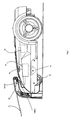
- the docking station 10 comprises a power wire 12, a second printed circuit board 14 electrically connected with the power wire 12, and a conductive terminal group connected with the output end of the second printed circuit board 14;
- the conductive terminal group comprises at least a first conductive terminal 16 and a second conductive terminal 18 (due to the angle, the first conductive terminal 16 and the second conductive terminal 18 in the figure are overlapped).
- the robot 50 comprises a docking terminal group electrically connected to the conductive terminal group, a first printed circuit board 58 electrically connected with the docking terminal group, a moving mechanism controlled by the first printed circuit board 58, and a power storage unit 56 supplying power to the robot 50, the docking terminal group at least comprises a first docking terminal 60 and a second docking terminal 62 (due to the angle, the first conductive terminal 60 and the second conductive terminal 62 in the figure are overlapped).
- the moving mechanism further comprises a motor 52 and wheels 54 driven by the motor 52. When the robot 50 requires recharging, the moving mechanism drives the robot 50 to return to the docking station 10 to try to dock with the docking station 10.
- the second printed circuit board 14 further comprises a power supply unit 20, a signal detection unit 24, a second power detection unit 26, an output power control unit 30 and a docking station control unit 28.
- the power supply unit 20 is configured for converting an external DC or AC into a power supply suitable for supplying charging power to the power storage unit 56 and can selectively apply power to the first conductive terminal 16 and the second conductive terminal 18;
- the signal detection unit 24 is electrically connected with the first conductive terminal 16 for detecting signals transferred between the first conductive terminal 16 and the second conductive terminal 18 and transferring the detected signals to the docking station control unit 28;
- the signal detection unit 24 can change the electric parameters of the signals passing therethrough, such as amplifying and decreasing the signal amplitude or changing the signal frequency and the signal type, such as changing the received sine wave signals into square wave signals;
- the second power detection unit 26 is configured for detecting the charging power applied by the power supply unit 20 to the first conductive terminal 16 and the second conductive terminal 18 and transferring the detected signals to the docking station control unit
- the second printed circuit board 14 also comprises an across circuit 78 placed between the first conductive terminal 16 and a second conductive terminal 18; the across circuit 78 is configured for electrically communicating with the first conductive terminal 16 and the second conductive terminal 18 to transmit signals and/or power between them.
- the first printed circuit board 58 further comprises a first signal conversion unit 70, a second signal conversion unit 72, a first power detection unit 74, an input power control unit 88 and a robot control unit 76, wherein the robot control unit 76 further comprises a signal transmission module 92 and a signal receiving module 94; the first signal conversion unit 70 is set between the first docking terminal 60 and the signal transmission module 92; and the second conversion unit 72 is set between the signal receiving module 94 and the second docking terminal 62.
- the signal transmission module 92 is configured for generating and transferring signals, the transferred signal passes through the first signal conversion unit 70; the first signal conversion unit 70 is configured for changing the electric parameters of the flowing signal, such as amplifying or decreasing the signal amplitude and changing the signal frequency and signal type, and transferring the transmitted signals to the first docking terminal 60; the second signal conversion unit 72 is configured for transmitting the signals received by the second docking terminal 62 from the outside and transferring the transmitted signals to the signal receiving module 94, and can change the electric parameters of the flowing signal; the first power detection unit 74 is configured for detecting the charging power transferred from the first docking terminal 60 and the second docking terminal 62 to the power storage unit 56 and transferring the detected signals to the robot control unit 76; the input power control unit 88 controls the power transferring from the first docking terminal 60 and the second docking terminal 62 to the power storage unit 56; the robot control unit 76 sends out a corresponding control signals according to the detected signals provided by the second signal conversion unit 72 and the first power detection unit 74, and
- the first power detection unit 74 further comprises a charging power detection unit 80 and a storage power detection unit 82; the charging power detection unit 80 is configured for detecting the power applied by the first docking terminal 60 and the second docking terminal 62 onto the power storage unit 56; and the storage power detection unit 82 is configured for detecting the current power of the power storage unit 56.
- the signal transmission module 92 sends out a predetermined detection signal to the first docking terminal 60 via the first signal conversion unit 70; at the same time, the signal receiving module 94 detects the signals transferred from the second docking terminal 62 via the second signal conversion unit 72 and determines if the received signal is a predetermined feedback signal corresponding to the predetermined detection signal.
- the predetermined detection signal sent from the signal transmission module 92 is transferred to the first docking terminal 60 via the first signal conversion unit 70; the first docking terminal 60 transfers the received signals to the first conductive terminal 16; the first conductive terminal 16 transfers the received signal to the second conductive terminal 18 via the across circuit 78; the second conductive terminal 18 transfers the received signal to the second docking terminal 62; the second docking terminal 62 transfers the received signal to the signal receiving module 94 via the second signal conversion unit 72; by transferring in the communication loop including the first signal conversion unit 70, the first docking terminal 60, the first conducive terminal 16, the cross circuit 78, the second conductive terminal 18, the second docking terminal 62 and the second signal conversion unit 72, the predetermined detection signal sent by the signal transmission module 92 is converted into the corresponding feedback signal and transferred to the signal receiving module 94.
- the robot control unit 76 verifies that the docking between the docking terminal group of the robot 50 and the conductive terminal group of the docking station 10 has succeeded, and then the robot control unit 76 controls the robot 50 to stop moving; otherwise, when the conductive terminal group is not electrically connected with the docking terminal group, it fails to form the communication loop between the signal transmission module 92 and the signal receiving module 94, so the predetermined detection signal sent by the signal transmission module 92 fails to return to the signal receiving module 94 via the communication loop and the signal receiving module 94 therefore fails to receive the predetermined feedback signal corresponding to the predetermined detection signal, and at this moment the robot control unit 76 verify that the docking between the docking terminal of the robot 50 and the conductive terminal group of the docking station 10 has not succeeded; and then the signal transmission module 92 will continue to send out the predetermined detection signals.
- the signal transferred by the first docking terminal 60 passes through the first conductive terminal 16, the across circuit 78 and the second conductive terminal 18.
- the signal detection unit 24 detects the signal, converts the signal into a predetermined startup signal corresponding to the predetermined detection signal and feeds it to the docking station control unit 28; after detecting the predetermined startup signal, the docking station control unit 28 verifies if the docking between the docking terminal group of the robot 50 and the conductive terminal group of the docking station 10 has succeeded, and if so, begins charging process and transfers a control signal to control the output power control unit 30 to permit the power supply unit 20 to provide power to the first conductive terminal 16 and the second conductive terminal 18; and the docking station 10 starts to charge the robot 50.
- the second power detection unit 26 detects the charging power transferred from the power supply unit 20 to the first conductive terminal 16 and the second conductive terminal 18 in real time and transfers the detected signal to the docking station control unit 28; once detecting that the charging power exceeds a predetermined level, the docking station control unit 28 controls the output power control unit 30 to prevents providing power from the power supply unit 20 to the first conductive terminal 16 and the second conductive terminal 18, and thus, the charging process is ended.
- the first power detection unit 74 of the robot 50 detects the power applied by the first docking terminal 60 and the second docking terminal 62 to the power storage unit 56, and transfers the detected signal to the robot control unit 76. Once detecting that the charging power exceeds a predetermined level, the robot control unit 76 controls the input power control unit 88 to stop power transferred from the first docking terminal 60 and the second docking terminal 62 to the power storage unit 56.
- both the docking station control unit 28 and the robot control unit 76 can judge if the charging time exceeds a predetermined value by setting a timer so as to control the stoppage of the power transferring. Besides, the robot control unit 76 can also judge if the power transferring requires being stopped by detecting the inner signal of the power storage unit 56, such as detecting the inner temperature of the power storage unit 56. For example, when the internal temperature of the power storage unit 56 exceeds the predetermined temperature level, the robot control unit 76 stops the power transmission from the first docking terminal 60 and the second docking terminal 62 to the power storage unit 56 so as to stop charging the power storage unit 56. After being fully recharged, the robot 50 can return to the working area 102 to work continuously.
- the robot 50 and the docking station 10 both verify that the docking has succeeded by verifying the docking between the docking terminal group of the robot 50 and the conductive terminal group of the docking station 10 only once, and then starts charging process. In actual situations, there is time difference between the detecting the predetermined feedback signal and the stopping of the robot 50, so after the robot 50 stops moving, the conductive terminal group and the docking terminal group may be separated.
- the robot control unit 76 verifies that docking between the docking terminal group of the robot 50 and the conductive terminal group of the docking station 10 has succeeded the first time and controls the robot 50 to stop moving, the signal transmission module 92 re-sends out the predetermined detection signal, and if the signal receiving module 94 receives the predetermined feedback signal corresponding to the predetermined detection signal again, the robot control unit 76 verifies that docking between the docking terminal group of the robot 50 and the conductive terminal group of the docking station 10 has succeeded again, and controls the moving mechanism to maintain the stop state; otherwise, if the signal receiving module 94 does not receive the predetermined feedback signal corresponding to the predetermined detection signal, the robot control unit 76 does not verify that the docking between the docking terminal group of the robot 50 and the conductive terminal group of the docking station 10 has succeeded, and controls the robot 50 to start moving.
- the re-sent out predetermined detection signal may be identical with or different from that sent out before the robot 50 stops moving.
- the robot 50 twice verifies that the docking between the docking terminal group of the robot 50 and the conductive terminal group of the docking station 10 has succeeded; correspondingly, the docking station 10 starts charging process after twice verifying that the docking has succeeded, wherein the first verification is done before the robot 50 stops moving, and the second verification is done after the robot 50 stops moving.
- the docking station 10 is also can be set to start charging process by once verifying that the docking between the docking terminal group of the robot 50 and the conductive terminal group of the docking station 10 has succeeded, in which the condition for verifying that the docking has succeeded is that the docking station control unit 28 receives the predetermined startup signal corresponding to the predetermined detection signal sent out by the signal transmission module 92 the second time.
- the mode of starting charging process after once verification is simpler, but the anti-interference performance of the former one is better than the later one.
- the above mentioned verification process includes two verification steps, wherein each step may include many sub-steps, and in each sub-step, the signal transmission module 92 can send out a different predetermined detection signal; correspondingly, if the signal receiving module 94 receives the predetermined feedback signals corresponding to the different detection signals, the docking between the docking terminal group of the robot 50 and the conductive terminal group of the docking station 10 can be verified as successful, and if the docking station control unit 28 receives the predetermined startup signals corresponding to the different predetermined detection signals, the docking between the docking terminal group of the robot 50 and the conductive terminal group of the docking station 10 can be verified as successful.
- each step for verifying that the docking between the docking terminal group of the robot 50 and the conductive terminal group of the docking station 10 has succeeded only includes one sub-step; in the verification process includes two verification steps, the signal transmission module 92 can send out a different predetermined detection signal; correspondingly, if the signal receiving module 94 receives the predetermined feedback signals corresponding to the different predetermined detection signals, the docking between the docking terminal group of the robot 50 and the conductive terminal group of the docking station 10 can be verified as successful, it means if the docking station control unit 28 receives the predetermined startup signals corresponding to the other predetermined detection signals, the docking between the docking terminal group of the robot 50 and the conductive terminal group of the docking station 10 can be verified as successful.
- the first conductive terminal 16, the second conductive terminal 18, the first docking terminal 60 and the second docking terminal 62 are configured for signal transferring during docking process and power transferring during charging process.
- the variation of the first scheme is that: the first conductive terminal 16, the second conductive terminal 18, the first docking terminal 60 and the second docking terminal 62 are only used for signal transferring only, and other terminals are set to transfer the power.
- the predetermined detection signal is transferred to the first docking terminal 60 by the first signal conversion unit 70; the signal received by the second docking terminal 62 is transferred to the signal receiving module 94 via the second signal conversion unit 72; the signal sent out by the signal transmission module 92 and the signal received by the signal receiving module 94 both are converted by the signal conversion unit to enable the subsequent circuit to transfer, receive, and identify the signals; therefore, under the basic conditions where the subsequent circuit can transfer, receive, and identify the signals, the signal from the signal transmission module 92 may pass through the first signal conversion unit 70 to be transferred, or be directly transferred without passing through the first signal conversion unit 70; and the signal transferred from the second docking terminal 62 to the signal receiving module 94 may pass through the second signal conversion unit 72 to be transferred, or be directly transferred without passing through the second conversion unit 72.
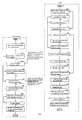
- the robot 50 is set with many ways to initial returning process, e.g.: expiration of the working time, completion of the work, insufficient power, exposure to rain, manual immediately charging, etc., all can be used as the conditions of the robot 50 for returning to the docking station 10; and when detecting any one of the above mentioned conditions, the robot control unit 76 controls the robot 50 to return to the docking station 10.
- the detection of the expiration of the working time and completion of the work can be implemented by setting a timer in the robot control unit 76.
- the robot 50 is controlled to return to the docking station 10, in which the detailed implementation is known to those skilled persons in this field and therefore is omitted here.
- the detection of insufficient power is implemented by the storage power detection unit 82 which detects the current residual power of the power storage unit 56 constantly and feeds back the detected result to the robot control unit 76.
- the robot control unit 76 controls the robot 50 to return to the docking station 10 so as to recharge the power storage unit 56;
- the predetermined threshold value is determined according to the chemical features of the power storage unit 56, and the working state of the robot 50, etc., to ensure that the power storage unit 56 can be fully used after being recharged and to avoid a situation where the robot 50 cannot return to the docking station 10 because of power exhaustion of the power storage unit 56.
- the detection of exposure to rain is implemented by setting a rain detector on the housing surface of the robot 50; the rain detector is electrically connected with the robot control unit 76; in case of exposure to rain, the rain detector generates and transfers a corresponding signal to the robot control unit 76, then the robot control unit 76 controls the robot 50 to return to be recharged, and this means it can effectively avoid damage to the robot 50 because of rain.
- a forced charging assembly is set on the housing surface of the robot 50, the forced charging assembly is electrically connected with the robot control unit 76; when detecting the manual immediately charging request from a user, the forced charging assembly can convert the manual immediately charging request into an electric signal and transmit the signal to the robot control unit 76, then the robot control unit 76 controls the robot 50 to return to the docking station 10.
- each functional unit of the second printed circuit board 14 and the first printed circuit board 58 are described in detail with reference to the figure 4 .
- the functional units of the first printed circuit board 58 go first.
- the robot control unit 76 comprises a signal transmission module 92 and a signal receiving module 94 and therefore has the functions of generating, transmitting and receiving signals.
- the robot control unit 76 can make judgments according to the received signals and transmit corresponding control signals and therefore shall have the functions of identification, judgment, generation of control signals according to the signal judgment results, etc.
- the robot control unit 76 can be set to many forms, such as an analogue circuit, a digital circuit, and the combination of a simulating circuit and digital circuit.
- the robot control unit 76 implements the above mentioned functions in the format of digital circuit, namely a microcontroller which is a well-known integrated circuit unit capable of completing related actions to implement corresponding functions by compiling the predetermined program.
- the microcontroller has the advantages of: the microcontroller is integrated with the functions of detection, identification, judgment, generation, and transmission of signals, timing, and calculation, etc.; and the components are simplified.
- the microcontroller has many models and can be selected according to the functional demands.
- the selected microcontroller has the functions of detection, identification, judgment, generation, and transmission of signals, timing, calculation, etc.
- the robot control unit 76 uses the microcontroller to implement all the functions, the functions of the signal transmission module 92 and the signal receiving module 94 are built into the microcontroller.
- the microcontroller of the robot control unit 76 is a microcontroller MCU1.
- the microcontroller MCU1 further comprises first signal receiving ports RX1, RX2, RX3, RX4, and RX5, and first signal transmission ports TX1 and TX2, wherein the first signal receiving port RX1 is electrically connected with the second signal conversion unit 72 for receiving the signal transferred from the second signal conversion unit 72; the first signal receiving port RX2 is electrically connected with the charging power detection unit 80 for receiving the signal of the power transmission from the first docking terminal 60 and the second docking terminal 62 to the power storage unit 56 from the charging power detection unit 80; the first signal receiving port RX3 is electrically connected with the storage power detection unit 82 for receiving the current power of the power storage unit 56 transferred by the storage power detection unit 82; the first signal receiving port RX4 is electrically connected with the forced charging assembly for receiving the signal from the forced charging assembly; the first signal receiving port RX5 is electrically connected with the rain detector for receiving the signal from the rain detector; the first signal transmission port TX1 is electrically connected with the first signal conversion unit 70 for transmitting the predetermined detection signal generated by the
- the microcontroller MCU1 continuously sends the predetermined detection signal in various formats, such as sine wave, square wave, and pulse signal.
- the sine wave signal has high anti-interference performance; compared with the sine wave signal, the square signal is easier to be generated and identified by the microcontroller; preferably, this embodiment adopts the square wave signal.
- square wave signals such as a square wave signal with a constant pulse width and a constant period, a square wave signal with a constant period and an increasing pulse width, a square wave signal with a constant pulse width and an increasing period, a square wave signal with an increasing pulse width and an increasing period, a square wave signal with a pulse with and a period one increasing and the other reducing, etc.
- the square wave signal having an amplitude, a pulse width and a period unchanged, as shown in figure 5 is adopted as the predetermined detection signal.
- the amplitude of the predetermined detection signal is the same as the working voltage amplitude Vcc of the microcontroller MCU1.
- the working voltage amplitude of the microcontroller MCU1 may be 3-5V.
- the working voltage amplitude of the microcontroller MCU1 is 5V, so the amplitude of the predetermined detection signal is 5V.
- the predetermined detection signal passes through and is correspondingly converted by the first signal conversion unit 70 and then is transferred to the first docking terminal 60, or is directly transferred to the first docking terminal 60 without passing through the first signal conversion unit 70.
- the first signal conversion unit 70 performs necessary conversion on the flowing signals.
- the conversion includes amplification, reduction, and period and type change of the signal, etc.
- the amplification or reduction of the signal can be easily implemented, but the period or type change of the signal shall be implemented with a special chip, which is complicated.
- the aim of the first signal conversion unit 70 converting the signal is to facilitate transmission and identification of the signal in the subsequent loop.
- the first signal conversion unit 70 amplifies the signal passing therethrough. There are many ways to amplify the signal.
- the first signal conversion unit 70 can be set into a combination of resistors and switch transistors, or a combination of resistors and a computing amplifier.
- the combination of resistors and switch transistors is adopted as the first signal conversion unit 70, including resistors R8 and R9 and the switch transistors Q1 and Q3, wherein the collector electrode of the switch transistor Q1 is electrically connected with the positive electrode of the power storage unit 56; the switch transistor Q3 is electrically connected with the negative electrode of the power storage unit 56; one end of the resistor R9 is electrically connected with the first signal transmission port TX1 and the other end is connected with the base electrode of the switch transistor Q3.
- the predetermined detection signal When the predetermined detection signal has a high level, it controls the switch transistor Q3 to be switched on via the resistor R9 and puts the base electrode of the switch transistor Q1 at a low level state via the resistor R8, and then the switch transistor Q1 is switched on; furthermore, to enable the positive electrode of the power storage unit 56 electrically connected with the first docking terminal 60, which means that the signal applied to the first docking terminal 60 has a high level.
- the predetermined detection signal when it has a low level, it controls the switch transistor Q3 to be switch off via the resistor R9 and puts the electrode of the switch transistor Q1 at a high level via the resistor R8; when the switch transistor Q1 is switched off, no power is applied to the first docking terminal 60, so the signal applied to the first docking terminal 60 has a low level.
- the signal applied to the first docking terminal 60 After being converted by the first signal conversion unit 70, the signal applied to the first docking terminal 60 is a square signal of which the period and pulse width are the same as those of the predetermined detection signal, but the amplitude is different, wherein the amplitude is equal to the voltage of the power storage unit 56.
- the voltage of the power storage unit 56 is higher than the working voltage Vcc of the microcontroller MCU1, so the first signal conversion unit 70 amplifies the amplitude of the predetermined detection signal, which has the advantages of strengthening the predetermined detection signal and avoiding a situation where the signal cannot be detected by the detection unit after being further reduced by the subsequent circuit.
- the collector electrode of the switch transistor Q1 may also be set to be electrically connected with the working power supply Vcc of the microcontroller MCU1. In this state, the first signal conversion unit 70 will not change the predetermined detection signal.
- the collector electrode of the switch transistor Q1 may also be set to be electrically connected with a power supply lower than the working voltage Vcc of the microcontroller MCU1. In this state, the first signal conversion unit 70 reduces the predetermined detection signal.
- the subsequent circuit may also detect the predetermined detection signal. But it should be noted that the subsequent transmission and detection units shall have a small impedance to avoid excessive consumption of the predetermined detection signal to excessively reduce the signal.
- the second signal conversion unit 72 also performs necessary conversion to facilitate signal transmission and identification in the subsequent circuit.
- the second signal conversion unit 72 is arranged between the second docking terminal 62 and the first signal receiving ports of the microcontroller MCU1, and the second signal conversion unit 72 converts the signal to facilitate the microcontroller MCU1 to indentify the signal, while the first signal conversion unit 70 amplifies the signal, so the second signal conversion unit 72 is set to reduce the signal passing therethrough.
- the second signal conversion unit 72 may be set to be a circuit consisting of resistors and a computing amplifier, resistors and switch transistors, or resistors and an optical coupler, etc.
- the second signal conversion unit 72 is the combination of the resistors and the optical coupler so as to form two separate parts, wherein the first part communicates with the second docking terminal 62 and the second part communicates with the first signal receiving port RX1 to implement electrical isolation between the external circuit and the internal circuit and avoid damage to the internal circuit caused by electrostatic power which may be encountered in the second docking terminal 62.
- the structure of the second signal conversion unit 72 can be seen in figure 4 , comprising a resistor R6 electrically connected with the second docking terminal 62, a resistor R5 with one end electrically connected with the first signal receiving port RX1 and the other end electrically connected with the working power supply Vcc of the microcontroller MCU1, and an optical coupler U1 isolating R5 and R6.
- the light-emitting part of the optical coupler U1 is connected in series with the resistor R6, while the receiving part of the optical coupler U1 is connected in series with the resistor R5; when the signal passing through the resistor R6 has a high level, the light-emitting part of the optical coupler U1 emits light, while the receiving part of the optical coupler U1 is switched on, and at this moment, the signal received by the first signal receiving port RX1 has a low level; when the signal flowing through the resistor R6 has a low level, the light-emitting part of the optical coupler U1 does not emit light, while the receiving part of the optical coupler U1 is switched off; at this moment the signal received by the first signal receiving port RX1 has a high level, and the amplitude of the high-level signal is the working voltage Vcc of the microcontroller MCU1.
- the second signal conversion unit 72 inverts the phase of the flowing signal and converts the signal into a signal with an amplitude of Vcc, which means that the second signal conversion unit 72 inverts the phase and reduces the signal passing therethrough; besides, the optical coupler is used to isolate the electrical signal, so the second signal conversion unit 72 inverts the phase, reduces, and isolates the signal.
- the resistor R5 may also be not electrically connected with the working power supply Vcc of the microcontroller MCU1, but connected with other constant power supply.
- the resistor R5 when the resistor R5 is electrically connected with a power supply with a constant voltage, such as 3V, 4V and 6V, the amplitude of the signal received by the first signal receiving port RX1 is the corresponding voltage, in which the details are omitted here.
- a constant voltage such as 3V, 4V and 6V
- the charging power detection unit 80 is used for detecting the charging power in the charging process where the docking station 10 charges the robot 50 and transfers the detection result to the robot control unit 76.
- the charging power detection unit 80 may be set into a functional circuit for detecting the current, voltage or detecting the current and voltage at the same time.
- the microcontroller MCU1 controls the input power control unit 88 to stop power transmission from the first docking terminal 60 and the second docking terminal 62 to the power storage unit 56 according to the signal received by the charging power detection unit 80 so as to stop the charging process of the docking station 10 charging the robot 50.
- current detection is set, which means that the charging power detection unit 80 detects the current signal transferred from the first docking terminal 60 and the second docking terminal 62 to the power storage unit 56. There are many ways to detect the current.
- the current detection is implemented by the way of combining a micro-resistor and a computing amplifier which is well-known in this field.
- the charging power detection unit 80 comprises a micro-resistor arranged between the first docking terminal 60 and the positive electrode of the power storage unit 56, and a computing amplifier A1 which amplifies the voltage applied to the resistor R24 and transfers the amplified signal to the second signal receiving port RX2.
- the microcontroller MCU1 After detecting the voltage applied to the resistor R24 via the second signal receiving port RX2, the microcontroller MCU1 performs corresponding computation to judge the current flowing through the resistor R24 so as to obtain the value of the current transferred from the first docking terminal 60 and the second docking terminal 62 to the power storage unit 56.
- the microcontroller MCU1 When detecting that the current value is less than a predetermined current value, the microcontroller MCU1 controls the input power control unit 88 to stop the power transmission from the first docking terminal 60 and the second docking terminal 62 to power storage unit 56 so as to stop the charging process that the docking station 10 charges the robot 50.
- the predetermined current value is set according to the properties of the power storage unit 56.
- the power storage unit 56 is a lead-acid battery, and according to its properties, the predetermined current value is 200mA.
- the input power control unit 88 is used for controlling the power transmission from the first docking terminal 60 and the second docking terminal 62 to the power storage unit 56 according to the control signal sent by the microcontroller MCU1 when the docking station 10 charges the robot 50.
- the input power control unit 88 at least can be set as a combination of a driving circuit and an MOSFET, or the combination of a driving circuit and a relay.
- the combination of a driving circuit and the MOSFET is adopted in this embodiment, wherein the MOSFET Q5 is arranged between the first docking terminal 60 and the positive electrode of the power storage unit 56; the driving circuit is set between the first signal transmission port TX2 and the MOSFET; and the driving circuit further comprises a resistor R10 and a resistor R11 for driving the MOSFET, a switch transistor Q4, and a resistor R12 and a resistor R13 for driving the switch transistor Q4.
- the microcontroller MCU1 sends the low-level signal via the second signal transmission port TX2 to control the switching-off of the switch transistor Q4 so as to control the switching-off of the MOSFET Q5 and avoid a situation where the control circuit consumes the power of the power storage unit 56.
- the microcontroller MCU1 sends the high-level signal via the first signal transmission port TX2 to control the switching-on of the switch transistor Q4 so as to control the switching-on of the MOSFET Q5 and allow the power transmission from the first docking terminal 60 and the second docking terminal 62 to the power storage unit 56, which means allowing the docking station 10 to charge the robot 50.
- the charging power detection unit 80 detects the current transmission from the first docking terminal 60 and the second docking terminal 62 to the power storage unit 56 constantly and transfers the detection signal to the microcontroller MCU1 via the first signal receiving port RX2; once detecting that the current is less than 200mA, the microcontroller MCU1 sends the low-level signal via the first signal transmission port TX2 to control the switching-off of the switch transistor Q4 so as to control the switching-off of the MOSFET Q5 and stop the power transmission from the first docking terminal 60 and the second docking terminal 62 to the power storage unit 56, which means stopping the charging process that the docking station 10 charges the robot 50.
- the storage power detection unit 82 is mainly used for detecting the power of the power storage unit 56 when the robot 50 works and is being charged, and transfers the detection signal to the first signal receiving port RX3; the microcontroller MCU1 judges if the power of the power storage unit 56 exceeds a predetermined value according to the received signal and sends a corresponding control signal according to the judgment results to control the working state of the input power control unit 88.
- the microcontroller MCU1 controls the robot 50 to return to the docking station 10 while detecting that the power of the power storage unit 56 is lower than a predetermined value; when the robot 50 is being charged, the microcontroller MCU1 sends a stop charging command to the input power storage unit 88 to stop charging the robot 50 when detecting that the power of the power storage unit 56 is higher than a predetermined value.
- the current power of the power storage unit 56 can be detected by various means, such as measuring the voltage of the power storage unit 56, measuring the discharging current or charging current of the power storage unit 56, or calculating the discharging or charging time. In this embodiment, the means of measuring the voltage of the power storage unit 56 is adopted because it is easy to implement.
- the storage power detection unit 82 comprises a resistor R15 and a resistor R16; the resistor R15 and the resistor R16 are connected in series to form a voltage divider to measure the voltage of the power storage unit 56.
- the predetermined voltage value during charging and the predetermined voltage value during discharging are correspondingly set according to the characteristics of the power storage unit 56.
- the predetermined voltage value is usually higher than 90% of the nominal voltage of the power storage unit 56, which can ensure that the robot 50 works fully and that the robot 50 can return to the docking station 10 to recharge the power storage unit 56 before the power of the power storage unit 56 is exhausted; and when the robot 50 is being charged, the predetermined voltage value is usually higher than 10% of the nominal voltage of the power storage unit 56.
- the power storage unit 56 is a lead-acid battery; the nominal voltage of this kind of battery is 24V, so the predetermined voltage value during work is 21.6V.
- the lead-acid battery usually determines whether to stop charging process or not by means of judging the charging current, so the signal of the storage power detection unit 82 in this embodiment is not used as the condition for judging whether the charging process shall be stopped, and at this moment the predetermined voltage during charging process is not limited.
- the forced charging assembly is mainly used for quickly responding to the manual immediately charging demands of a user and transmitting the demands to microcontroller MCU1 in the format of an electric signal.
- This function can be implemented by various means, such as acoustic sensing, touch sensing, etc. Compared with acoustic sensing, touch sensing is simpler and more convenient and is therefore adopted in this embodiment.
- the forced charging assembly can be set into a normally-on switch or a trigger switch, preferably the trigger switch. As shown in figure 4 , one end of the switch SW1 is electrically connected with the negative electrode of the power storage unit 56, and one end is electrically connected with the first signal receiving port RX4 of the robot control unit 76.
- the first signal receiving port RX4 is at a high-impedance state; once the user switches on the switch SW1, the first signal receiving port RX4 can receive the low level, and the robot control unit 76 responds to the low level received by the first signal receiving port RX4 to control the robot 50 to return to the docking station 10 so as to charge the power storage unit 56.
- a rain detector is used for detecting if the robot 50 is exposed to rain, and if so, transmitting the detected signal to the robot control unit 76; the robot control unit 76 controls the robot 50 to return to the docking station 10 to take a shelter from the rain so as to avoid the rain corroding the robot 50.
- a rain detector can be implemented by two mutually isolated metal plates, wherein one metal plate is electrically connected with the first signal receiving port RX5 of the microcontroller MCU1, and the other is electrically connected with the negative electrode of the power storage unit 56; when it does not rain, the two metal plates maintain the isolated state, and the first signal receiving port RX5 is suspended; and when it rains, the two metal plates are connected by the rain, the first signal receiving port RX5 receives the low-level signal, and then the microcontroller MCU1 controls the robot 50 to return to the docking station 10 to take shelter from the rain.
- the two metal plates conduct the function of a switch, and thus a rain detector is illustrated by the switch SW2 as shown in figure 4 .
- the docking station control unit 28 is mainly used for receiving signals from the signal detection unit 24 and the second power detection unit 26 and controlling the working of the output power control unit 30 according to the signals. Based on the above mentioned functions, the docking station control unit 28 can be set into various forms, such as an analogue circuit, a digital circuit, or the combination of an analogue circuit and a digital circuit.
- the docking station control unit 28 is in the format of a microcontroller, namely a microcontroller which is a well-known integrated circuit unit capable of completing related actions to implement corresponding functions by compiling the predetermined program.
- the microcontroller has many models and can be selected according to the functional demands.
- the selected microcontroller has the functions of detection, identification, judgment, generation, and transmission of signals, timing, calculation, etc.
- the microcontroller included in the docking station control unit 28 is a microcontroller MCU2.
- the microcontroller MCU2 further comprises the second signal receiving ports RX1 and RX2 and a second signal transmission port TX1, wherein the second signal receiving port RX1 is electrically connected with the signal detection unit 24 for receiving the signal transferred from the first signal conversion unit 70; the second signal receiving port RX2 is electrically connected with the second power detection unit 26 for receiving the signal of the power transmission from the power supply unit 20 to the first conductive terminal 16 and the second conductive terminal 18 from the second power detection unit 26; and the second signal transmission port TX1 is electrically connected with the output power control unit 30 for transmitting the control signal to the output power control unit 30 to control the power transmission from the power supply unit 20 to the first conductive terminal 16 and the second conductive terminal 18.
- the microcontroller MCU2 controls the signal output of the second signal transmission port T
- the signal detection unit 24 is mainly used for detecting the signal flowing through the first conductive terminal 16 and the second conductive terminal 18 and transmitting the detected signal to the docking station control unit 28. To detect the signal flowing through the first conducive terminal 16 and the second conductive terminal 18, the signal detection unit 24 must have a detection part across the first conducive terminal 16 and the second conductive terminal 18 and a transmission part which transfers the signal detected by the detection part to the microcontroller MCU2.
- the across circuit 78 has the function of connecting the first conducive terminal 16 and the second conductive terminal 18. This function is identical with that of the detection part of the signal detection unit 24. To simplify the circuit, the function of the detection part of the signal detection unit 24 is set in the across circuit 78, so the functions of two circuits are implemented by one circuit.
- the across circuit 78 comprises a resistor R2 and a light-emitting part of an optical coupler U2 which are arranged in series between the first conducive terminal 16 and the second conductive terminal 18.
- the transmission part of the signal detection unit 24 comprises a resistor R1 and a receiving part of the optical coupler U2 which are arranged in series between the working power supply Vdd of the microcontroller MCU2 and the second conductive terminal 18, and a wire is arranged between the joint of the resistor R1 and the receiving part of the optical coupler U2 and the second signal receiving port RX1 of the microcontroller MCU2 to transmit the detected signal to the microcontroller MCU2.
- the resistor R1 and the receiving part of the optical coupler U2 may also be arranged in series between the other working power supply and the second conductive terminal 18 according to the actual demands.
- the signal passes through the first conductive terminal 16
- the signal further passes through the across circuit 78 consisting of the resistor R2 and the light-emitting part of the optical coupler U2; if the voltage of the signal is big enough to drive the light-emitting part to emit light, then the light-emitting part will emit light.
- the voltage value is usually more than or equal to 0.6V.
- the light-emitting part of the optical coupler U2 emits light, meanwhile the receiving part of the optical coupler U2 receives a light source and is switched on, and thus the microcontroller MCU2 receives a low-level signal from the second conductive terminal 18.
- the microcontroller MCU2 receives a high-level signal from the resistor R1, wherein the voltage amplitude of the high-level signal is equal to the voltage value of the power supply provided on the resistor R1, in this embodiment is VDD.
- the working voltage of the microcontroller MCU2 VDD is usually lower than the voltage of the power storage unit 56, so the signal detection unit 24 reduces the signal amplified by the first signal conversion unit 70 and inverts the phase.
- the working voltage VDD of the microcontroller MCU2 may be identical with or different from the working voltage Vcc of the microcontroller MCU1, and preferably, the VDD is identical with the Vcc.
- the second power detection unit 26 is used for detecting the power transmission from the power supply unit 20 to the first conductive terminal 16 and the second conductive terminal 18 and transmitting the detected signal to the docking station control unit 28.
- the microcontroller MCU2 controls the output power control unit 30 to stop the power transmission from the power supply unit 20 to the first conductive terminal 16 and the second conductive terminal 18 so as to stop the charging process where the docking station 10 charges the robot 50.
- Power detection can be implemented by detecting the current or the voltage or detecting the current and voltage at the same time.
- the second power detection unit 26 detects the current signal from the power supply unit 20 to the first conductive terminal 16 and the second conductive terminal 18.
- Current detection can be implemented by various means.
- the combination of a micro-resistor and a computing amplifier well-known in this field is adopted.
- the second power detection unit 26 comprises a micro-resistor R17 arranged between the power supply unit 20 and the second conductive terminal 18 and a computing amplifier A2 which amplifies the signal applied to the resistor R17 and transfers the amplified signal to the second signal receiving port RX2.
- the microcontroller MCU2 performs corresponding computation after detecting the voltage applied to the resistor R17 via the second signal receiving port RX2, and judges the current flowing through the resistor R17, and then the value of the current flowing from the power supply unit 20 to the first conductive terminal 16 and the second conductive terminal 18.
- the microcontroller MCU2 controls the output power control unit 30 to stop the power transmission from the power supply unit 20 to the first conductive terminal 16 and the second conductive terminal 18 so as to stop the charging process that the docking station 10 charges the robot 50.
- the predetermined current value is set according to the characteristics of the power storage unit 56.
- the power storage unit 56 is a lead-acid battery, so according to its characteristics, the predetermined current value is 200mA.
- the output power control unit 30 has a function of operationally allowing or stopping the power transmission from the power supply unit 20 to the first conductive terminal 16 and the second conductive terminal 18 according to the control signal sent from the microcontroller MCU2. Based on the above mentioned function, the output power control unit 30 at least may be the combination of a driving circuit and a MOSFET or the combination of a driving circuit and a relay.
- the MOSFET can cut off the power transmission from the power supply unit 20 to the first conductive terminal 16 and the second conductive terminal 18, but there is still a micro-current flowing through the first conductive terminal 16 and the second conductive terminal 18; if the power supply unit 20 is not an isolated power supply, even if there is only a micro-current flowing through the first conductive terminal 16 and the second conductive terminal 18, the human body may be injured because of electric shock if the human body contacts the micro-current.
- the output power control unit 30 is set into the combination of a driving circuit and a relay.
- the output power control unit 30 comprises a driving circuit and a relay coil KM arranged between the positive electrode and negative electrode of the power supply unit 20, a relay switch K1 arranged between the positive electrode of the power supply unit 20 and the first conductive terminal 16, and a relay switch K2 arranged between the negative electrode of the power supply unit 20 and the second conducive terminal 18, wherein the driving circuit further comprises resistors R3 and R4, a switch transistor Q2, and a fly-wheel diode D4 connected with the relay coil KM in parallel.
- the switch K1 and the switch K2 are switched off to ensure that the first conductive terminal 16 and the second conductive terminal 18 have no output to avoid injury of human body.
- the microcontroller MCU2 sends the high-level signal via the second signal transmission port TX1 to switch on the switch transistor Q2; the relay coil KM generates a magnetic force by means of the flowing current to close the switch K1 and the switch K2 to allow the power transmission from the power supply unit 20 to the first conducive terminal 16 and the second conductive terminal 18, which means allowing the docking station 10 to charge the robot 50.
- the second power detection unit 26 detects the current transmission from the power supply unit 20 to the first conducive terminal 16 and the second conductive terminal 18 constantly and transfers the detected signal to the microcontroller MCU2 via the second signal receiving port RX2.
- the microcontroller MCU2 sends the low-level signal via the second signal transmission port TX1 to switch off the switch transistor Q2; the relay coil KM loses the magnetic force because of lacking current flow, and the switch k1 and the switch k2 are switched off to stop the power transmission from the power supply unit 20 to the first conducive terminal 16 and the second conductive terminal 18, namely stop the docking station 10 from charging the robot 50.
- the power supply unit 20 is used for converting the external power supply into a power supply suitable for the robot 50.
- the external power supply includes the DC power supply or AC power supply.
- the power supply suitable for charging the robot 50 is determined according to the electric properties of the power supply unit 56, and usually is the DC power supply. Therefore, if the external power supply is a DC power supply, the power supply unit 20 is only required to adjust the voltage of the DC power supply into the charging voltage suitable for the robot 50. In such circumstance, the power supply unit 20 can be designed into a voltage adjusting circuit. In this field, it is well-known that there are various voltage adjusting circuits, so the details are omitted here.
- the power supply unit 20 can be designed into a circuit in the mode of a switch power supply or in the mode of a transformer to convert the AC power supply into DC power supply suitable for charging the robot 50, or a regular voltage-reduction rectifier circuit can be adopted to convert the external AC power supply into DC power supply suitable for charging the robot 50, wherein the circuit in the mode of the switch power supply or in the mode of the transformer is the isolating circuit well-known in this field.
- the regular voltage-reduction rectifier circuit is not an isolating circuit which has the advantage of low cost and also has a serious heating problem.
- the external AC power supply is not isolated and therefore is very dangerous to the human body and easily causes injury due to electric shock.
- the microcontroller MCU1 sends the predetermined detection signal via the first signal transmission port TX1; the amplitude of the predetermined detection signal is Vcc; after the predetermined detection signal is converted by the first signal conversion unit 70 into the signal of the amplitude in the voltage of the power supply unit 56, so the amplitude is enhanced; after the detection signal is converted by the first signal conversion unit 70, which means that the first signal conversion unit 70 amplifies the signal passing therethrough and further transfers the amplified signal to the first docking terminal 60 and further to the first conductive terminal 16; the first conductive terminal 16 further transfers the amplified signal to the second conductive terminal 18 via the across circuit 78; the across circuit 78 only includes a resistance component, so the power flowing through the cross circuit 78 will be reduced, but other properties are not changed; the second conductive terminal 18 further transfers the signal to the second docking terminal 62; the second docking terminal
- the signal is amplified or reduced, and the type of the signal is not changed, so if the predetermined detection signal is a signal varying regularly, the predetermined feedback signal finally generated by conversion in the mentioned loop is a signal varying regularly; if the predetermined detection signal is a square wave signal, the predetermined feedback signal finally generated by conversion in the mentioned loop is a square wave signal without change in the electric parameters, wherein the electric parameters include the amplitude, period, duty ratio, etc.; and by means of conversion in the mentioned loop, the difference between the predetermined feedback signal finally received by the microcontroller MCU1 and the predetermined detection signal sent by the microcontroller MCU1 is only the inverted phase.
- the first signal receiving port RX1 After the first signal receiving port RX1 receives the predetermined feedback signal with a period identical with that of the predetermined detection signal, it can be regarded as that the first conductive terminal 16 and the second conductive terminal 18 are in electric connection with the first docking terminal 60 and the second docking terminal 62 respectively, which means that it can be verified that the docking between the docking terminal group of the robot 50 and the conductive terminal group of the docking station 10 has succeeded; on the contrary, if the first conductive terminal 16 and the second conductive terminal 18 are not in electric connection with the first docking terminal 60 and the second docking terminal 62 respectively, and the microcontroller MCU1 cannot detect the predetermined feedback signal with a period identical with that of the predetermined detection signal, it cannot be verified that the docking between the docking terminal group of the robot 50 and the conductive terminal group of the docking station 10 has succeeded, and the microcontroller MCU1 continuously sends the predetermined detection signal.
- the predetermined detection signal is only amplified after passing through the first signal conversion unit 70, the first docking terminal 60, the first conductive terminal 16 and the cross circuit 78.
- the amplified signal passes through the across circuit 78, the light-emitting part of the optical coupler U2 located in the across circuit 78 is selected to emit light or not according to the signal level so as to selectively connect the second signal receiving port RX1 and the VDD or not, which is similar to the signal detection unit 24 converts the signal as before mentioned, the signal flowing through the across circuit 78 is finally converted into a signal with an inverted phase and amplitude VDD and then fed back to the second receiving port RX1.
- Vcc is identical with VDD, so the predetermined startup signal has an amplitude identical with that of the predetermined detection signal and an inverted phase.
- the signal is amplified first and then reduced and inverted, so the predetermined startup signal and the predetermined detection signal belong to the same type; if the predetermined detection signal is a signal varying regularly, the predetermined startup signal finally generated by means of conversion is a signal varying regularly; if the predetermined detection signal is a square wave signal, the predetermined startup signal finally generated by means of conversion is a square wave signal.
- the predetermined detection signal is a square wave signal with a constant period, so the predetermined startup signal is a square wave signal of which the period is a predetermined value.
- the microcontroller MCU2 After detecting the predetermined startup signal, the microcontroller MCU2 verifies that the docking between the docking terminal group of the robot 50 and the conductive terminal group of the docking station 10 has succeeded. Based on the above description, when the microcontroller MCU1 verifies that docking between the docking terminal group of the robot 50 and the conductive terminal group of the docking station 10 has succeeded, the microcontroller MCU2 verifies that docking between the docking terminal group of the robot 50 and the conductive terminal group of the docking station 10 has succeeded.
- the microcontroller MCU1 controls the robot 50 to stop moving.
- the microcontroller MCU1 may also control the robot 50 to stop moving after verifying the successful docking several times.
- the predetermined detection signal sent each time may be identical or different, e.g.: the predetermined detection signal sent each time can be different by changing the frequency of the pulse signal, the duty ratio, etc.
- the microcontroller MCU1 controls the robot 50 to stop moving after verifying that that the docking between the docking terminal group of the robot 50 and the conductive terminal group of the docking station 10 has succeeded only once.
- the microcontroller MCU1 After the robot 50 stops moving, the microcontroller MCU1 re-sends the predetermined detection signal, if detecting the predetermined feedback signal corresponding to the re-sent predetermined detection signal, the microcontroller MCU1 verifies that the docking terminal group of the robot 50 and the conductive terminal group of the docking station 10 has succeeded again, and controls the robot 50 to maintain the stop state; if detecting no predetermined feedback signal corresponding to the re-sent predetermined detection signal, the microcontroller MCU1 does not verify that the docking terminal group of the robot 50 and the conductive terminal group of the docking station 10 has succeeded again, and then controls the robot 50 to start to move.
- the sent predetermined detection signal may be identical with or different from that before the robot 50 stops moving, preferably different to facilitate identification of the microcontroller MCU1.
- the microcontroller MCU1 verifying or not verifying that the docking terminal group of the robot 50 and the conductive terminal group of the docking station 10 has succeeded the microcontroller MCU2 also does the same work.
- the microcontroller MCU2 After he microcontroller MCU2 verifying that the docking terminal group of the robot 50 and the conductive terminal group of the docking station 10 has succeeded, the microcontroller MCU2 starts charging process and controls the output power control unit 30 to allow the power transmission from the power supply unit 20 to the first conductive terminal 16 and the second conductive terminal 18.
- the microcontroller MCU2 can start charging process by making the verification once or twice. If charging process is started by making the verification once, the microcontroller MCU2 preferably makes the verification by detecting the predetermined startup signal corresponding to the predetermined detection signal sent by the microcontroller MCU1 at the second time.
- the predetermined detection signal is finally converted into the corresponding predetermined feedback signal by the first signal conversion unit 70, the first docking terminal 60, the first conductive terminal 16, the across circuit 78, the second conductive terminal 18, the second docking terminal 62 and the second signal conversion unit 72.
- the first signal conversion unit 70 amplifies the flowing signal; the across circuit 78 does not convert the signal; the second signal conversion unit 72 correspondingly reduces the flowing signal and inverts the phase, so the predetermined feedback signal is a signal identical with the predetermined detection signal in type, amplitude and period and opposite to the predetermined detection signal in phase.
- the first variation of this embodiment is that: the robot 50 does not have the first signal conversion unit 70 and the second signal conversion unit 72; the predetermined detection signal is converted into the corresponding predetermined feedback signal by the first docking terminal 60, the first conductive terminal 16, the across circuit 78, the second conductive terminal 18, and the second docking terminal 62.
- the predetermined feedback signal and the predetermined detection signals are signals with all the same parameters.
- the robot 50 is provided with either the first signal conversion unit 70 or the second signal conversion unit 72; the predetermined detection signal is converted into the corresponding predetermined feedback signal by the first docking terminal 60, the first conductive terminal 16, the cross circuit 78, the second conductive terminal 18, the second docking terminal 62 and either the first signal conversion unit 70 or the second signal conversion unit 72; either the first signal conversion unit 70 or the second signal conversion unit 72 amplifies or reduces the signal or changes the signal type.
- the feedback signal can be preset in the MCU2 according to the signal conversion carried out by either the first signal conversion unit 70 or the second signal conversion unit 72, in which the details of this way are well-known in the field and therefore are omitted here.
- This embodiment also has many other variations.
- the robot 50 is provided with both first signal conversion unit 70 and the second signal conversion unit 72, but the first signal conversion unit 70 reduces the signal, changes the signal type or others, while the second signal conversion unit 72 also carries out the corresponding conversion, in which the details are omitted here.
- the predetermined detection signal is finally converted into the corresponding predetermined startup signal by the first signal conversion unit 70, the first docking terminal 60, the first conductive terminal 16, the second conductive terminal 18, and the signal detection unit 24.
- This embodiment also has many other variations.
- the docking station 10 is not provided with the signal detection unit 24, or the signal detection unit 24 changes the type of the flowing signal or makes corresponding change according to the conversion carried out by the first signal conversion unit 70, wherein the basic method is the same as the conversion carried out by the first signal conversion unit 70 and the second signal conversion unit 72 and therefore is omitted here.
- the case where the microcontroller MCU1 sends the signal via the first docking terminal 60 and receives the signal via the second docking terminal 62 is described.
- the following is the case where the microcontroller MCU1 sends the signal via the second docking terminal 62 and receives the signal via the first docking terminal 60; compared with the previous one, this case has the following differences: the first signal conversion unit 70 is in electric connection with the second docking terminal 62; the second signal conversion unit 72 is in electric connection with the first docking terminal 60; meanwhile, the electric connection between the across circuit 78 and the first conductive terminal 16 and the second conductive terminal 18 are opposite in direction.
- a signal detection unit 24 can be added to instead of reversely connecting the across circuit 78.
- the added signal detection unit 24 is also in electric connection with the microcontroller MCU2 and is only different from the previous signal detection unit 24 in that the direction of the electric connection between the across circuit 78 and the first conductive terminal 16 and the second conductive terminal 18 is opposite to that in the previous case.
- the signal entering the docking station 10 from the first conductive terminal 16 or the second conductive terminal 18 can be detected by the microcontroller MCU2, wherein this way is well-known to those skilled in this field and therefore is omitted here.
- the first conductive terminal 16 and the second conductive terminal 18 may not be respectively connected with the first docking terminal 60 and the second docking terminal 62, which means that if the first conductive terminal 16 is docked with the first docking terminal 60 and the second conductive terminal 18 is docked with the second docking terminal 62, then the microcontroller MCU1 and the microcontroller MCU2 may verify that the docking between the docking terminal group of the robot 50 and the docking station 10 has succeeded; and if the first conductive terminal 16 is docked with the second docking terminal 62, and the second conductive terminal 18 is docked with the first docking terminal 60, then the microcontroller MCU1 and the microcontroller MCU2 may also verify that the docking between the docking terminal group of the robot 50 and the docking station 10 has succeeded.
- the flowchart includes two parts, wherein the left part is the workflow chart of the microcontroller MCU2 in the docking station 10, and the right part is the workflow chart of the microcontroller MCU1 in the robot 50.
- step S0 the microcontroller MCU1 controls the robot 50 to work in the working area 102 defined by the boundary wire 100 according to the predetermined rules, as shown in step S1; the microcontroller MCU1 enters the step S2 to detect if the switch SW1 is switched on and judge if the user sends a charging command via the forced charging assembly, and if the judgment result is yes, it enters the step S5; otherwise, the microcontroller MCU1 enters step S3 to detect if the switch SW2 is switched on and judges if it is exposed to rain, and if the judgment result is yes, it enters step S5; otherwise, the microcontroller MCU1 enters step S4 to detect if the voltage value of the power storage unit 56 is lower than 21.6V via the storage power detection unit 82, which means that if the current power of the power storage unit 56 is lower than the predetermined value; in the step S4, if the judgment result is no, returns
- the microcontroller MCU2 After the docking station 10 is connected with the external power supply, the microcontroller MCU2 initials, as shown in step S20; the microcontroller MCU2 enters step S22 to stop the power transmission from the power supply unit 20 to the first conductive terminal 16 and the second conductive terminal 18; the microcontroller MCU2 enters step S23 to detect if the predetermined startup signal is received, and when the conductive terminal group is electrically connected with the docking terminal group, the predetermined detection signal sent by the microcontroller MCU1 is received by the microcontroller MCU2 after passing through the signal detection unit 24 and also is received by the microcontroller MCU2 at the same time; in step S24, the microcontroller MCU2 verifies that the docking between the docking terminal group of the robot 50 and the conductive terminal group of the docking station 10 has succeeded after detecting the predetermined startup signal; in step S25, the microcontroller MCU2 does not act, but continuously detects if the predetermined startup signal is received again, and if the pre
- the microcontroller MCU2 After the docking station 10 starts charging process, the microcontroller MCU2 enters step S27 to control the output power control unit 30 to allow the power transmission from the power supply unit 20 to the first conductive terminal 16 and the second conductive terminal 18; the microcontroller MCU2 enters step S28 to detect the current transferred from the power supply unit 20 to the first conductive terminal 16 and the second conductive terminal 18 by the second energy detection unit 26; next, the microcontroller MCU2 enters step S30 to judge if the current is less than 200mA, and if the judgment result is no, returns to step S28; if the judgment result is yes, the microcontroller MCU2 enters step S32 to control the output power control unit 30 to stop the power transmission from the power supply unit 20 to the first conductive terminal 16 and the second conductive terminal 18 so as to stop the charging process that the docking station 10 charges the robot 50.
- Both microcontroller MCU2 and microcontroller MCU1 detect and control the charging process.
- step S16 after verifying that the docking between the docking terminal group of the robot 50 and the conductive terminal group of the docking station 10 has succeeded, the microcontroller MCU1 detects the current transferred from the first docking terminal 60 and the second docking terminal 62 to the power storage unit 56; in next step S17, the microcontroller MCU1 further judges if the current is less than the predetermined value 200mA, if no, it returns to step S16, and if yes, it stops the power transmission from the first docking terminal 60 and the second docking terminal 62 to the power storage unit 56 by the input power control unit 88 so as to stop the docking station 10 from charging the robot 50, as shown in step S 18.
- the robot 50 and the docking station 10 are respectively provided with a charging power detection unit 80 and a second power detection unit 26 inside to detect the charging current, and a robot control unit 76 and a docking station control unit 28 inside for judging if the charging process needs to continue according to the charging current.
- the charging power detection unit 80 is set closer the power storage unit 56, so the detection result is more precise in comparison with the second power detection unit 26.
- the robot 50 must be provided with a charging power detection unit 80 inside.
- the microcontroller MCU1 Under the condition of keeping the first conductive terminal 16 and the second conductive terminal 18 in corresponding electric connection with the first docking terminal 60 and the second docking terminal 62, the microcontroller MCU1 detects that the charging current is less than 200mA prior to the microcontroller MCU2; then after the microcontroller MCU1 controls the input power control unit 88 to stop the power transmission from the first docking terminal 60 and the second docking terminal 62 to the power storage unit 56, the power transmission from the first docking terminal 60 and the second docking terminal 62 to the power storage unit 56 is cut off, then the microcontroller MCU2 detects if the current transferred from the power supply unit 20 to the first conductive terminal 16 and the second conductive terminal 18 is less than 200mA and therefore also controls the output power control unit 30 to stop the power transmission from the power supply unit 20 to the first conductive terminal 16 and the second conductive terminal 18.
- the docking station 10 is also provided with a charging current detection unit and a power control unit to overcome the injury in a situation where the one or two groups of terminals of the first conductive terminal 16 and the second conductive terminal 18, the first docking terminal 60 and the second docking terminal 62 of the docking station 10 and the robot 50 are separated from each other.
- a charging current detection unit and a power control unit to overcome the injury in a situation where the one or two groups of terminals of the first conductive terminal 16 and the second conductive terminal 18, the first docking terminal 60 and the second docking terminal 62 of the docking station 10 and the robot 50 are separated from each other.
- the microcontroller MCU2 shall stop the power transmission from the power supply unit 20 to the first conductive terminal 16 and the second conductive terminal 18 to effectively guard the human body against the injury due to electric shock caused by contacting the first conductive terminal 16 or the second conductive terminal 18.
- the robot 50 may be a lawn mower, a dust collector, an industrial robot, etc. If the robot 50 is a lawn mower, it further includes a cutting assembly; the cutting assembly comprises a cutting motor and a cutting blade; and when the lawn mower works in the working area 102 defined by the boundary line 100, the cutting motor drives the cutting blade to rotate to cut grass.
Landscapes
- Engineering & Computer Science (AREA)
- Physics & Mathematics (AREA)
- Power Engineering (AREA)
- Aviation & Aerospace Engineering (AREA)
- Radar, Positioning & Navigation (AREA)
- Remote Sensing (AREA)
- General Physics & Mathematics (AREA)
- Automation & Control Theory (AREA)
- Mechanical Engineering (AREA)
- Electromagnetism (AREA)
- Charge And Discharge Circuits For Batteries Or The Like (AREA)
- Control Of Position, Course, Altitude, Or Attitude Of Moving Bodies (AREA)
- Electric Vacuum Cleaner (AREA)
- Harvester Elements (AREA)
Applications Claiming Priority (5)
| Application Number | Priority Date | Filing Date | Title |
|---|---|---|---|
| CN201010568709.3A CN102475015B (zh) | 2010-11-30 | 2010-11-30 | 自动行走设备 |
| CN201010568706.XA CN102480156B (zh) | 2010-11-30 | 2010-11-30 | 对接方法 |
| CN201010568704.0A CN102480146B (zh) | 2010-11-30 | 2010-11-30 | 对接系统 |
| CN201010568707.4A CN102480147B (zh) | 2010-11-30 | 2010-11-30 | 充电站 |
| PCT/CN2011/083133 WO2012072024A1 (fr) | 2010-11-30 | 2011-11-29 | Dispositif de marche automatique, poste de charge, système de connexion et procédé de connexion |
Publications (3)
| Publication Number | Publication Date |
|---|---|
| EP2648307A1 true EP2648307A1 (fr) | 2013-10-09 |
| EP2648307A4 EP2648307A4 (fr) | 2016-11-09 |
| EP2648307B1 EP2648307B1 (fr) | 2019-08-28 |
Family
ID=46171206
Family Applications (1)
| Application Number | Title | Priority Date | Filing Date |
|---|---|---|---|
| EP11844275.5A Active EP2648307B1 (fr) | 2010-11-30 | 2011-11-29 | Dispositif de marche automatique, poste de charge, système de connexion et procédé de connexion |
Country Status (3)
| Country | Link |
|---|---|
| US (1) | US8676378B2 (fr) |
| EP (1) | EP2648307B1 (fr) |
| WO (1) | WO2012072024A1 (fr) |
Cited By (24)
| Publication number | Priority date | Publication date | Assignee | Title |
|---|---|---|---|---|
| USD758455S1 (en) | 2015-06-05 | 2016-06-07 | Mtd Products Inc | Robotic mower body |
| USD760806S1 (en) | 2015-06-05 | 2016-07-05 | Mtd Products Inc | Robotic mower |
| USD781349S1 (en) | 2016-02-16 | 2017-03-14 | Mtd Products Inc | Robotic mower housing |
| USD792198S1 (en) | 2015-10-29 | 2017-07-18 | Mtd Products Inc | Caster wheel |
| USD794089S1 (en) | 2015-06-05 | 2017-08-08 | Mtd Products Inc | Wheel |
| USD795299S1 (en) | 2016-02-16 | 2017-08-22 | Mtd Products Inc | Blade |
| USD795300S1 (en) | 2016-08-23 | 2017-08-22 | Mtd Products Inc | Blade |
| USD797530S1 (en) | 2015-06-05 | 2017-09-19 | Mtd Products Inc | Blade |
| WO2017190788A1 (fr) * | 2016-05-04 | 2017-11-09 | Alfred Kärcher Gmbh & Co. Kg | Système de traitement du sol et procédé pour faire fonctionner un tel système de traitement du sol |
| US9829891B2 (en) | 2013-03-15 | 2017-11-28 | Mtd Products Inc | Autonomous mobile work system comprising a variable reflectivity base station |
| US9930829B2 (en) | 2015-05-27 | 2018-04-03 | Mtd Products Inc | Self-cleaning mower blade assembly |
| CN108589599A (zh) * | 2018-04-28 | 2018-09-28 | 上海仙途智能科技有限公司 | 无人清扫系统 |
| US10212880B2 (en) | 2016-06-24 | 2019-02-26 | Mtd Products Inc | High-efficiency cutting system |
| USD848488S1 (en) | 2016-08-23 | 2019-05-14 | Mtd Products Inc | Robotic mower housing |
| US10433480B2 (en) | 2016-04-20 | 2019-10-08 | Mtd Products Inc | Low-energy blade system having a quick-attach mechanism |
| DE102018214450A1 (de) * | 2018-08-27 | 2020-02-27 | BSH Hausgeräte GmbH | Impedanzerkennung eines Verbrauchers an einer Ladestation |
| DE102018214449A1 (de) * | 2018-08-27 | 2020-02-27 | BSH Hausgeräte GmbH | Ladestation für einen Verbraucher, Anordnung umfassend den Verbraucher und die Ladestation sowie Verfahren |
| US10698417B2 (en) | 2016-05-06 | 2020-06-30 | Mtd Products Inc | Autonomous mower navigation system and method |
| USD889517S1 (en) | 2019-01-31 | 2020-07-07 | Mtd Products Inc | Robotic mower body |
| USD892187S1 (en) | 2018-11-30 | 2020-08-04 | Mtd Products Inc | Robotic mower |
| US10806076B2 (en) | 2017-10-06 | 2020-10-20 | Mtd Products Inc | High-efficiency lawn maintenance tool and high-efficiency cutting blade |
| US11000170B2 (en) | 2016-05-04 | 2021-05-11 | Alfred Kärcher SE & Co. KG | Floor cleaning system |
| US11033166B2 (en) | 2016-05-04 | 2021-06-15 | Alfred Kärcher SE & Co. KG | Floor treatment system |
| US11109729B2 (en) | 2016-05-04 | 2021-09-07 | Alfred Kärcher SE & Co. KG | Floor treatment system |
Families Citing this family (34)
| Publication number | Priority date | Publication date | Assignee | Title |
|---|---|---|---|---|
| US20110221387A1 (en) * | 2010-03-09 | 2011-09-15 | Robert Louis Steigerwald | System and method for charging an energy storage system for an electric or hybrid-electric vehicle |
| US20120191517A1 (en) | 2010-12-15 | 2012-07-26 | Daffin Jr Mack Paul | Prepaid virtual card |
| KR101964372B1 (ko) * | 2012-11-21 | 2019-04-01 | 한화디펜스 주식회사 | 도킹 모듈 |
| GB2509991B (en) * | 2013-01-22 | 2015-03-11 | Dyson Technology Ltd | Docking station for a mobile robot |
| GB2509989B (en) * | 2013-01-22 | 2015-03-04 | Dyson Technology Ltd | Docking station for a mobile robot |
| US9469208B2 (en) * | 2013-03-15 | 2016-10-18 | Symbotic, LLC | Rover charging system |
| US9124101B2 (en) | 2013-04-02 | 2015-09-01 | Bel Fuse (Macao Commercial Offshore) Limited | Power supply having selectable operation based on communications with load |
| US10518651B2 (en) | 2014-01-16 | 2019-12-31 | Husqvarna Ab | Robotic work tool system and a charging connector arrangement for a robotic work tool system |
| WO2016046756A1 (fr) * | 2014-09-26 | 2016-03-31 | Nokia Technologies Oy | Procédé et appareil pour des mesures inter-fréquence à double connectivité |
| JP6251154B2 (ja) * | 2014-11-11 | 2017-12-20 | 東芝テック株式会社 | ドッキングステーションとその制御プログラム |
| KR101640706B1 (ko) * | 2015-01-28 | 2016-07-18 | 엘지전자 주식회사 | 진공 청소기 |
| US20160276851A1 (en) * | 2015-03-16 | 2016-09-22 | Unitronics Automated Solutions Ltd. | System and method for managing batteries used in a distributed facility |
| USD760649S1 (en) | 2015-06-22 | 2016-07-05 | Mtd Products Inc | Docking station |
| US11003192B2 (en) * | 2015-11-10 | 2021-05-11 | Positec Power Tools (Suzhou) Co., Ltd. | Automatic working system and control method thereof and automatic moving device |
| CN105691231B (zh) * | 2016-03-10 | 2018-11-06 | 中车株洲电力机车有限公司 | 快速充电的控制方法、车载系统及地面充电站控制系统 |
| US10286799B2 (en) * | 2016-08-23 | 2019-05-14 | GM Global Technology Operations LLC | Hands-free conductive battery charger for an electric vehicle |
| US9807930B1 (en) | 2016-08-25 | 2017-11-07 | Irobot Corporation | Blade guard for a robot lawnmower |
| CN106597923A (zh) * | 2016-11-23 | 2017-04-26 | 河池学院 | 多功能教育机器人控制器 |
| EP3412131B1 (fr) | 2017-06-09 | 2020-11-11 | Andreas Stihl AG & Co. KG | Système de traitement de sol comprenant une adaptation de signal |
| EP3412134B1 (fr) * | 2017-06-09 | 2020-08-19 | Andreas Stihl AG & Co. KG | Système de traitement de sol comprenant un câble périphérique continu |
| EP3412132B1 (fr) | 2017-06-09 | 2021-05-12 | Andreas Stihl AG & Co. KG | Système de traitement de sol comprenant au moins une zone intensive |
| EP3412135B1 (fr) * | 2017-06-09 | 2022-09-14 | Andreas Stihl AG & Co. KG | Système de traitement de sol avec au moins une station de charge comprenant une liaison de données |
| EP3412133B1 (fr) * | 2017-06-09 | 2022-09-14 | Andreas Stihl AG & Co. KG | Système de travail du sol comprenant au moins une station de charge |
| WO2019063066A1 (fr) * | 2017-09-26 | 2019-04-04 | Aktiebolaget Electrolux | Commande de déplacement d'un dispositif de nettoyage robotique |
| KR102449128B1 (ko) * | 2018-05-25 | 2022-09-29 | 삼성에스디아이 주식회사 | 전기적 연결성 검증 장치 |
| DE202018106517U1 (de) * | 2018-11-16 | 2020-02-21 | Vorwerk & Co. Interholding Gmbh | Saugreinigungsgerät mit einem Akkumulator |
| KR102302473B1 (ko) * | 2019-10-10 | 2021-09-16 | 엘지전자 주식회사 | 이동 로봇의 충전대 및 이동 로봇 시스템 |
| CN113576357B (zh) * | 2020-04-30 | 2023-02-10 | 海尔机器人科技(青岛)有限公司 | 扫地机器人工作站及其垃圾回收方法 |
| USD1032509S1 (en) | 2021-04-23 | 2024-06-25 | Mtd Products Inc | Docking station |
| SE545080C2 (en) | 2021-04-30 | 2023-03-21 | Husqvarna Ab | Method and system for charging a robotic work tool |
| USD971272S1 (en) | 2021-06-25 | 2022-11-29 | Mtd Products Inc | Robotic mower body |
| USD971271S1 (en) | 2021-06-25 | 2022-11-29 | Mtd Products Inc | Robotic mower |
| USD980874S1 (en) | 2021-07-23 | 2023-03-14 | Mtd Products Inc | Robotic mower body |
| USD980873S1 (en) | 2021-07-23 | 2023-03-14 | Mtd Products Inc | Robotic mower |
Family Cites Families (15)
| Publication number | Priority date | Publication date | Assignee | Title |
|---|---|---|---|---|
| US5324948A (en) | 1992-10-27 | 1994-06-28 | The United States Of America As Represented By The United States Department Of Energy | Autonomous mobile robot for radiologic surveys |
| US5440216A (en) | 1993-06-08 | 1995-08-08 | Samsung Electronics Co., Ltd. | Robot cleaner |
| JPH08335112A (ja) | 1995-06-08 | 1996-12-17 | Minolta Co Ltd | 移動作業ロボットシステム |
| ES2151014T3 (es) * | 1995-10-02 | 2000-12-16 | Wyss Patrick Impex | Procedimiento para la adaptacion automatica de un cargador y cargador correspondiente. |
| US6076226A (en) | 1997-01-27 | 2000-06-20 | Robert J. Schaap | Controlled self operated vacuum cleaning system |
| SE523080C2 (sv) | 1998-01-08 | 2004-03-23 | Electrolux Ab | Dockningssystem för självgående arbetsredskap |
| NL1020004C2 (nl) * | 2002-02-19 | 2003-08-21 | Lely Entpr Ag | Samenstel voor het voederen en melken van dieren, en werkwijze voor het voederen en voor het melken van dieren. |
| KR100468107B1 (ko) * | 2002-10-31 | 2005-01-26 | 삼성광주전자 주식회사 | 외부충전장치를 갖는 로봇청소기 시스템 및 로봇청소기의외부충전장치 접속방법 |
| US6888338B1 (en) * | 2003-01-27 | 2005-05-03 | O2Micro International Limited | Portable computer and docking station having charging circuits with remote power sensing capabilities |
| DE602005017749D1 (de) * | 2004-02-03 | 2009-12-31 | F Robotics Acquisitions Ltd | Roboter-dockstation und roboter zur verwendung damit |
| CN100370938C (zh) * | 2004-02-06 | 2008-02-27 | 泰怡凯电器(苏州)有限公司 | 自动吸尘器与充电座的对接方法 |
| CN1751650A (zh) * | 2005-09-22 | 2006-03-29 | 浙江大学 | 自动吸尘器的充电装置及其对接方法 |
| KR20080060535A (ko) * | 2006-12-27 | 2008-07-02 | 주식회사 유진로봇 | 자율 이동 로봇의 자동 충전 장치 및 그를 이용한 자동충전 방법 |
| US8607405B2 (en) * | 2008-03-14 | 2013-12-17 | Techtronic Floor Care Technology Limited | Battery powered cordless cleaning system |
| US20100070659A1 (en) * | 2008-09-17 | 2010-03-18 | Kenneth Ma | Method and system for operating and/or charging a battery powered usb device based on a usb port type |
-
2011
- 2011-11-29 WO PCT/CN2011/083133 patent/WO2012072024A1/fr active Application Filing
- 2011-11-29 EP EP11844275.5A patent/EP2648307B1/fr active Active
-
2012
- 2012-07-16 US US13/550,101 patent/US8676378B2/en active Active
Cited By (36)
| Publication number | Priority date | Publication date | Assignee | Title |
|---|---|---|---|---|
| US9829891B2 (en) | 2013-03-15 | 2017-11-28 | Mtd Products Inc | Autonomous mobile work system comprising a variable reflectivity base station |
| US9930829B2 (en) | 2015-05-27 | 2018-04-03 | Mtd Products Inc | Self-cleaning mower blade assembly |
| USD760806S1 (en) | 2015-06-05 | 2016-07-05 | Mtd Products Inc | Robotic mower |
| USD776169S1 (en) | 2015-06-05 | 2017-01-10 | Mtd Products Inc | Robotic mower |
| USD794089S1 (en) | 2015-06-05 | 2017-08-08 | Mtd Products Inc | Wheel |
| USD758455S1 (en) | 2015-06-05 | 2016-06-07 | Mtd Products Inc | Robotic mower body |
| USD797530S1 (en) | 2015-06-05 | 2017-09-19 | Mtd Products Inc | Blade |
| USD792198S1 (en) | 2015-10-29 | 2017-07-18 | Mtd Products Inc | Caster wheel |
| USD781349S1 (en) | 2016-02-16 | 2017-03-14 | Mtd Products Inc | Robotic mower housing |
| USD795299S1 (en) | 2016-02-16 | 2017-08-22 | Mtd Products Inc | Blade |
| USD799555S1 (en) | 2016-02-16 | 2017-10-10 | Mtd Products Inc | Robotic mower housing |
| US10433480B2 (en) | 2016-04-20 | 2019-10-08 | Mtd Products Inc | Low-energy blade system having a quick-attach mechanism |
| WO2017190788A1 (fr) * | 2016-05-04 | 2017-11-09 | Alfred Kärcher Gmbh & Co. Kg | Système de traitement du sol et procédé pour faire fonctionner un tel système de traitement du sol |
| EP3451890B1 (fr) | 2016-05-04 | 2023-03-22 | Alfred Kärcher SE & Co. KG | Système de traitement des sols et procédé d'operation d'un tel |
| CN109068926B (zh) * | 2016-05-04 | 2022-04-26 | 阿尔弗雷德·卡赫欧洲两合公司 | 地板处理系统和用于运行其的方法 |
| CN109068926A (zh) * | 2016-05-04 | 2018-12-21 | 阿尔弗雷德·卡赫欧洲两合公司 | 地板处理系统和用于运行其的方法 |
| US11272821B2 (en) | 2016-05-04 | 2022-03-15 | Alfred Kärcher SE & Co. KG | Floor treatment system and method for operating such a system |
| US11109729B2 (en) | 2016-05-04 | 2021-09-07 | Alfred Kärcher SE & Co. KG | Floor treatment system |
| US11033166B2 (en) | 2016-05-04 | 2021-06-15 | Alfred Kärcher SE & Co. KG | Floor treatment system |
| US11000170B2 (en) | 2016-05-04 | 2021-05-11 | Alfred Kärcher SE & Co. KG | Floor cleaning system |
| US10698417B2 (en) | 2016-05-06 | 2020-06-30 | Mtd Products Inc | Autonomous mower navigation system and method |
| US11687093B2 (en) | 2016-05-06 | 2023-06-27 | Mtd Products Inc | Autonomous mower navigation system and method |
| US10542670B2 (en) | 2016-06-24 | 2020-01-28 | Mtd Products Inc | High-efficiency cutting system |
| US11464164B2 (en) | 2016-06-24 | 2022-10-11 | Mtd Products Inc | High-efficiency cutting system |
| US10212880B2 (en) | 2016-06-24 | 2019-02-26 | Mtd Products Inc | High-efficiency cutting system |
| USD822068S1 (en) | 2016-08-23 | 2018-07-03 | Mtd Products Inc | Blade |
| USD848488S1 (en) | 2016-08-23 | 2019-05-14 | Mtd Products Inc | Robotic mower housing |
| USD795300S1 (en) | 2016-08-23 | 2017-08-22 | Mtd Products Inc | Blade |
| US10806076B2 (en) | 2017-10-06 | 2020-10-20 | Mtd Products Inc | High-efficiency lawn maintenance tool and high-efficiency cutting blade |
| CN108589599A (zh) * | 2018-04-28 | 2018-09-28 | 上海仙途智能科技有限公司 | 无人清扫系统 |
| DE102018214449A1 (de) * | 2018-08-27 | 2020-02-27 | BSH Hausgeräte GmbH | Ladestation für einen Verbraucher, Anordnung umfassend den Verbraucher und die Ladestation sowie Verfahren |
| DE102018214450A1 (de) * | 2018-08-27 | 2020-02-27 | BSH Hausgeräte GmbH | Impedanzerkennung eines Verbrauchers an einer Ladestation |
| EP3616976A1 (fr) | 2018-08-27 | 2020-03-04 | BSH Hausgeräte GmbH | Station de charge pour un consommateur, dispositif comprenant le consommateur et la station de charge ainsi que procédé |
| EP3617721A1 (fr) | 2018-08-27 | 2020-03-04 | BSH Hausgeräte GmbH | Reconnaissance d'impédance d'un consommateur d'une station de charge |
| USD892187S1 (en) | 2018-11-30 | 2020-08-04 | Mtd Products Inc | Robotic mower |
| USD889517S1 (en) | 2019-01-31 | 2020-07-07 | Mtd Products Inc | Robotic mower body |
Also Published As
| Publication number | Publication date |
|---|---|
| US20130006418A1 (en) | 2013-01-03 |
| US8676378B2 (en) | 2014-03-18 |
| EP2648307A4 (fr) | 2016-11-09 |
| WO2012072024A1 (fr) | 2012-06-07 |
| EP2648307B1 (fr) | 2019-08-28 |
Similar Documents
| Publication | Publication Date | Title |
|---|---|---|
| EP2648307B1 (fr) | Dispositif de marche automatique, poste de charge, système de connexion et procédé de connexion | |
| EP2658073B1 (fr) | Système d'accueil et procédé d'accueil pour un robot | |
| JP4956539B2 (ja) | 無接点充電方法及び無接点充電システム | |
| CN102931711B (zh) | 机器人自动充电系统及其充电方法 | |
| CN102480146B (zh) | 对接系统 | |
| RU2589028C2 (ru) | Способ и зарядная станция для электрической зарядки накопителя электрической энергии | |
| US7652450B2 (en) | Secondary battery charging device | |
| CN105098945A (zh) | 一种可直充电源适配器 | |
| CN102475015B (zh) | 自动行走设备 | |
| CN105098900A (zh) | 移动终端、可直充电源适配器及充电方法 | |
| CN104993562A (zh) | 可直充电源适配器 | |
| KR20080005020A (ko) | 무접점 충전 시스템 | |
| US8575892B2 (en) | Charging apparatus for moving robot and method thereof | |
| CN102545284B (zh) | 对接系统 | |
| US11979045B2 (en) | Smart connection device, jump starter, and battery clamp | |
| US20030184161A1 (en) | Power supply module for electrical power tools | |
| CN110138063B (zh) | 基于中大功率无线充电设备的匹配识别系统及其方法 | |
| CN102570519B (zh) | 自动行走设备 | |
| WO2022105658A1 (fr) | Système de travail automatique | |
| CN102856941B (zh) | 对接系统 | |
| CN102480156B (zh) | 对接方法 | |
| KR102433599B1 (ko) | 모션 센서가 있는 재충전 배터리 시스템 | |
| CN206135502U (zh) | 一种扫地机器人无线充电系统 | |
| CN110676892B (zh) | 移动机器人及其电源管理系统 | |
| CN105186615A (zh) | 智能供电模块 |
Legal Events
| Date | Code | Title | Description |
|---|---|---|---|
| PUAI | Public reference made under article 153(3) epc to a published international application that has entered the european phase |
Free format text: ORIGINAL CODE: 0009012 |
|
| 17P | Request for examination filed |
Effective date: 20130627 |
|
| AK | Designated contracting states |
Kind code of ref document: A1 Designated state(s): AL AT BE BG CH CY CZ DE DK EE ES FI FR GB GR HR HU IE IS IT LI LT LU LV MC MK MT NL NO PL PT RO RS SE SI SK SM TR |
|
| DAX | Request for extension of the european patent (deleted) | ||
| RA4 | Supplementary search report drawn up and despatched (corrected) |
Effective date: 20161012 |
|
| RIC1 | Information provided on ipc code assigned before grant |
Ipc: H02J 7/00 20060101AFI20161006BHEP |
|
| STAA | Information on the status of an ep patent application or granted ep patent |
Free format text: STATUS: EXAMINATION IS IN PROGRESS |
|
| 17Q | First examination report despatched |
Effective date: 20170908 |
|
| GRAP | Despatch of communication of intention to grant a patent |
Free format text: ORIGINAL CODE: EPIDOSNIGR1 |
|
| STAA | Information on the status of an ep patent application or granted ep patent |
Free format text: STATUS: GRANT OF PATENT IS INTENDED |
|
| INTG | Intention to grant announced |
Effective date: 20190502 |
|
| GRAS | Grant fee paid |
Free format text: ORIGINAL CODE: EPIDOSNIGR3 |
|
| GRAA | (expected) grant |
Free format text: ORIGINAL CODE: 0009210 |
|
| STAA | Information on the status of an ep patent application or granted ep patent |
Free format text: STATUS: THE PATENT HAS BEEN GRANTED |
|
| AK | Designated contracting states |
Kind code of ref document: B1 Designated state(s): AL AT BE BG CH CY CZ DE DK EE ES FI FR GB GR HR HU IE IS IT LI LT LU LV MC MK MT NL NO PL PT RO RS SE SI SK SM TR |
|
| REG | Reference to a national code |
Ref country code: GB Ref legal event code: FG4D |
|
| REG | Reference to a national code |
Ref country code: CH Ref legal event code: EP |
|
| REG | Reference to a national code |
Ref country code: AT Ref legal event code: REF Ref document number: 1173596 Country of ref document: AT Kind code of ref document: T Effective date: 20190915 |
|
| REG | Reference to a national code |
Ref country code: IE Ref legal event code: FG4D |
|
| REG | Reference to a national code |
Ref country code: DE Ref legal event code: R096 Ref document number: 602011061686 Country of ref document: DE |
|
| REG | Reference to a national code |
Ref country code: SE Ref legal event code: TRGR |
|
| REG | Reference to a national code |
Ref country code: NL Ref legal event code: MP Effective date: 20190828 |
|
| REG | Reference to a national code |
Ref country code: LT Ref legal event code: MG4D |
|
| PG25 | Lapsed in a contracting state [announced via postgrant information from national office to epo] |
Ref country code: BG Free format text: LAPSE BECAUSE OF FAILURE TO SUBMIT A TRANSLATION OF THE DESCRIPTION OR TO PAY THE FEE WITHIN THE PRESCRIBED TIME-LIMIT Effective date: 20191128 Ref country code: NL Free format text: LAPSE BECAUSE OF FAILURE TO SUBMIT A TRANSLATION OF THE DESCRIPTION OR TO PAY THE FEE WITHIN THE PRESCRIBED TIME-LIMIT Effective date: 20190828 Ref country code: HR Free format text: LAPSE BECAUSE OF FAILURE TO SUBMIT A TRANSLATION OF THE DESCRIPTION OR TO PAY THE FEE WITHIN THE PRESCRIBED TIME-LIMIT Effective date: 20190828 Ref country code: LT Free format text: LAPSE BECAUSE OF FAILURE TO SUBMIT A TRANSLATION OF THE DESCRIPTION OR TO PAY THE FEE WITHIN THE PRESCRIBED TIME-LIMIT Effective date: 20190828 Ref country code: PT Free format text: LAPSE BECAUSE OF FAILURE TO SUBMIT A TRANSLATION OF THE DESCRIPTION OR TO PAY THE FEE WITHIN THE PRESCRIBED TIME-LIMIT Effective date: 20191230 Ref country code: NO Free format text: LAPSE BECAUSE OF FAILURE TO SUBMIT A TRANSLATION OF THE DESCRIPTION OR TO PAY THE FEE WITHIN THE PRESCRIBED TIME-LIMIT Effective date: 20191128 Ref country code: FI Free format text: LAPSE BECAUSE OF FAILURE TO SUBMIT A TRANSLATION OF THE DESCRIPTION OR TO PAY THE FEE WITHIN THE PRESCRIBED TIME-LIMIT Effective date: 20190828 |
|
| PG25 | Lapsed in a contracting state [announced via postgrant information from national office to epo] |
Ref country code: RS Free format text: LAPSE BECAUSE OF FAILURE TO SUBMIT A TRANSLATION OF THE DESCRIPTION OR TO PAY THE FEE WITHIN THE PRESCRIBED TIME-LIMIT Effective date: 20190828 Ref country code: IS Free format text: LAPSE BECAUSE OF FAILURE TO SUBMIT A TRANSLATION OF THE DESCRIPTION OR TO PAY THE FEE WITHIN THE PRESCRIBED TIME-LIMIT Effective date: 20191228 Ref country code: GR Free format text: LAPSE BECAUSE OF FAILURE TO SUBMIT A TRANSLATION OF THE DESCRIPTION OR TO PAY THE FEE WITHIN THE PRESCRIBED TIME-LIMIT Effective date: 20191129 Ref country code: ES Free format text: LAPSE BECAUSE OF FAILURE TO SUBMIT A TRANSLATION OF THE DESCRIPTION OR TO PAY THE FEE WITHIN THE PRESCRIBED TIME-LIMIT Effective date: 20190828 Ref country code: AL Free format text: LAPSE BECAUSE OF FAILURE TO SUBMIT A TRANSLATION OF THE DESCRIPTION OR TO PAY THE FEE WITHIN THE PRESCRIBED TIME-LIMIT Effective date: 20190828 Ref country code: LV Free format text: LAPSE BECAUSE OF FAILURE TO SUBMIT A TRANSLATION OF THE DESCRIPTION OR TO PAY THE FEE WITHIN THE PRESCRIBED TIME-LIMIT Effective date: 20190828 |
|
| REG | Reference to a national code |
Ref country code: AT Ref legal event code: MK05 Ref document number: 1173596 Country of ref document: AT Kind code of ref document: T Effective date: 20190828 |
|
| PG25 | Lapsed in a contracting state [announced via postgrant information from national office to epo] |
Ref country code: TR Free format text: LAPSE BECAUSE OF FAILURE TO SUBMIT A TRANSLATION OF THE DESCRIPTION OR TO PAY THE FEE WITHIN THE PRESCRIBED TIME-LIMIT Effective date: 20190828 |
|
| PG25 | Lapsed in a contracting state [announced via postgrant information from national office to epo] |
Ref country code: RO Free format text: LAPSE BECAUSE OF FAILURE TO SUBMIT A TRANSLATION OF THE DESCRIPTION OR TO PAY THE FEE WITHIN THE PRESCRIBED TIME-LIMIT Effective date: 20190828 Ref country code: EE Free format text: LAPSE BECAUSE OF FAILURE TO SUBMIT A TRANSLATION OF THE DESCRIPTION OR TO PAY THE FEE WITHIN THE PRESCRIBED TIME-LIMIT Effective date: 20190828 Ref country code: DK Free format text: LAPSE BECAUSE OF FAILURE TO SUBMIT A TRANSLATION OF THE DESCRIPTION OR TO PAY THE FEE WITHIN THE PRESCRIBED TIME-LIMIT Effective date: 20190828 Ref country code: AT Free format text: LAPSE BECAUSE OF FAILURE TO SUBMIT A TRANSLATION OF THE DESCRIPTION OR TO PAY THE FEE WITHIN THE PRESCRIBED TIME-LIMIT Effective date: 20190828 Ref country code: PL Free format text: LAPSE BECAUSE OF FAILURE TO SUBMIT A TRANSLATION OF THE DESCRIPTION OR TO PAY THE FEE WITHIN THE PRESCRIBED TIME-LIMIT Effective date: 20190828 |
|
| PG25 | Lapsed in a contracting state [announced via postgrant information from national office to epo] |
Ref country code: CZ Free format text: LAPSE BECAUSE OF FAILURE TO SUBMIT A TRANSLATION OF THE DESCRIPTION OR TO PAY THE FEE WITHIN THE PRESCRIBED TIME-LIMIT Effective date: 20190828 Ref country code: SK Free format text: LAPSE BECAUSE OF FAILURE TO SUBMIT A TRANSLATION OF THE DESCRIPTION OR TO PAY THE FEE WITHIN THE PRESCRIBED TIME-LIMIT Effective date: 20190828 Ref country code: IS Free format text: LAPSE BECAUSE OF FAILURE TO SUBMIT A TRANSLATION OF THE DESCRIPTION OR TO PAY THE FEE WITHIN THE PRESCRIBED TIME-LIMIT Effective date: 20200224 Ref country code: SM Free format text: LAPSE BECAUSE OF FAILURE TO SUBMIT A TRANSLATION OF THE DESCRIPTION OR TO PAY THE FEE WITHIN THE PRESCRIBED TIME-LIMIT Effective date: 20190828 |
|
| REG | Reference to a national code |
Ref country code: DE Ref legal event code: R097 Ref document number: 602011061686 Country of ref document: DE |
|
| REG | Reference to a national code |
Ref country code: CH Ref legal event code: PL |
|
| PLBE | No opposition filed within time limit |
Free format text: ORIGINAL CODE: 0009261 |
|
| STAA | Information on the status of an ep patent application or granted ep patent |
Free format text: STATUS: NO OPPOSITION FILED WITHIN TIME LIMIT |
|
| PG2D | Information on lapse in contracting state deleted |
Ref country code: IS |
|
| PG25 | Lapsed in a contracting state [announced via postgrant information from national office to epo] |
Ref country code: LU Free format text: LAPSE BECAUSE OF NON-PAYMENT OF DUE FEES Effective date: 20191129 Ref country code: MC Free format text: LAPSE BECAUSE OF FAILURE TO SUBMIT A TRANSLATION OF THE DESCRIPTION OR TO PAY THE FEE WITHIN THE PRESCRIBED TIME-LIMIT Effective date: 20190828 Ref country code: CH Free format text: LAPSE BECAUSE OF NON-PAYMENT OF DUE FEES Effective date: 20191130 Ref country code: LI Free format text: LAPSE BECAUSE OF NON-PAYMENT OF DUE FEES Effective date: 20191130 |
|
| 26N | No opposition filed |
Effective date: 20200603 |
|
| REG | Reference to a national code |
Ref country code: BE Ref legal event code: MM Effective date: 20191130 |
|
| PG25 | Lapsed in a contracting state [announced via postgrant information from national office to epo] |
Ref country code: SI Free format text: LAPSE BECAUSE OF FAILURE TO SUBMIT A TRANSLATION OF THE DESCRIPTION OR TO PAY THE FEE WITHIN THE PRESCRIBED TIME-LIMIT Effective date: 20190828 |
|
| PG25 | Lapsed in a contracting state [announced via postgrant information from national office to epo] |
Ref country code: IE Free format text: LAPSE BECAUSE OF NON-PAYMENT OF DUE FEES Effective date: 20191129 |
|
| PG25 | Lapsed in a contracting state [announced via postgrant information from national office to epo] |
Ref country code: BE Free format text: LAPSE BECAUSE OF NON-PAYMENT OF DUE FEES Effective date: 20191130 |
|
| PG25 | Lapsed in a contracting state [announced via postgrant information from national office to epo] |
Ref country code: CY Free format text: LAPSE BECAUSE OF FAILURE TO SUBMIT A TRANSLATION OF THE DESCRIPTION OR TO PAY THE FEE WITHIN THE PRESCRIBED TIME-LIMIT Effective date: 20190828 |
|
| PG25 | Lapsed in a contracting state [announced via postgrant information from national office to epo] |
Ref country code: HU Free format text: LAPSE BECAUSE OF FAILURE TO SUBMIT A TRANSLATION OF THE DESCRIPTION OR TO PAY THE FEE WITHIN THE PRESCRIBED TIME-LIMIT; INVALID AB INITIO Effective date: 20111129 Ref country code: MT Free format text: LAPSE BECAUSE OF FAILURE TO SUBMIT A TRANSLATION OF THE DESCRIPTION OR TO PAY THE FEE WITHIN THE PRESCRIBED TIME-LIMIT Effective date: 20190828 |
|
| PG25 | Lapsed in a contracting state [announced via postgrant information from national office to epo] |
Ref country code: MK Free format text: LAPSE BECAUSE OF FAILURE TO SUBMIT A TRANSLATION OF THE DESCRIPTION OR TO PAY THE FEE WITHIN THE PRESCRIBED TIME-LIMIT Effective date: 20190828 |
|
| P01 | Opt-out of the competence of the unified patent court (upc) registered |
Effective date: 20230608 |
|
| PGFP | Annual fee paid to national office [announced via postgrant information from national office to epo] |
Ref country code: GB Payment date: 20231120 Year of fee payment: 13 |
|
| PGFP | Annual fee paid to national office [announced via postgrant information from national office to epo] |
Ref country code: SE Payment date: 20231117 Year of fee payment: 13 Ref country code: IT Payment date: 20231110 Year of fee payment: 13 Ref country code: FR Payment date: 20231124 Year of fee payment: 13 Ref country code: DE Payment date: 20231107 Year of fee payment: 13 |