EP2647971A1 - Appareil de mesure du niveau de remplissage et adaptateur doté d'un réflecteur - Google Patents
Appareil de mesure du niveau de remplissage et adaptateur doté d'un réflecteur Download PDFInfo
- Publication number
- EP2647971A1 EP2647971A1 EP12163195.6A EP12163195A EP2647971A1 EP 2647971 A1 EP2647971 A1 EP 2647971A1 EP 12163195 A EP12163195 A EP 12163195A EP 2647971 A1 EP2647971 A1 EP 2647971A1
- Authority
- EP
- European Patent Office
- Prior art keywords
- reflector
- waveguide
- adapter
- measuring device
- level measuring
- Prior art date
- Legal status (The legal status is an assumption and is not a legal conclusion. Google has not performed a legal analysis and makes no representation as to the accuracy of the status listed.)
- Withdrawn
Links
Images

Classifications
-
- G—PHYSICS
- G01—MEASURING; TESTING
- G01F—MEASURING VOLUME, VOLUME FLOW, MASS FLOW OR LIQUID LEVEL; METERING BY VOLUME
- G01F23/00—Indicating or measuring liquid level or level of fluent solid material, e.g. indicating in terms of volume or indicating by means of an alarm
- G01F23/22—Indicating or measuring liquid level or level of fluent solid material, e.g. indicating in terms of volume or indicating by means of an alarm by measuring physical variables, other than linear dimensions, pressure or weight, dependent on the level to be measured, e.g. by difference of heat transfer of steam or water
- G01F23/28—Indicating or measuring liquid level or level of fluent solid material, e.g. indicating in terms of volume or indicating by means of an alarm by measuring physical variables, other than linear dimensions, pressure or weight, dependent on the level to be measured, e.g. by difference of heat transfer of steam or water by measuring the variations of parameters of electromagnetic or acoustic waves applied directly to the liquid or fluent solid material
- G01F23/284—Electromagnetic waves
Definitions
- the present invention relates to the field of level measurement and in particular the field of level measurement with radar, wherein for level measurement electromagnetic waves, which are guided by a waveguide, are used.
- Level measuring devices with a signal generator for generating electromagnetic waves and an elongate waveguide for guiding the generated electromagnetic waves are known from the prior art.
- Such fill level measuring devices are generally used for level measurement of liquids, wherein the waveguide is designed as a cylindrical tube into which the filling material, d. H. especially the liquid, penetrates.
- the emitted and guided in the waveguide electromagnetic waves are at least partially reflected, so that by means of a transit time measurement of the level of the medium can be determined within the waveguide.
- Such a level measuring device is particularly suitable for liquids, such as solvents or liquid gases and liquids with foaming and for products with low dielectric conductivity ⁇ .
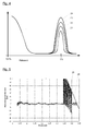
- FIG. 4 23 shows the regular measuring signal, ie the reflection of the electromagnetic wave at the surface of the medium and with the bottom reflection in a prior art level indicator at a filling level of approximately 0%.
- the bottom reflection 24 completely covers the measurement signal 23, so that a detection of the measurement signal 23 is not possible.
- FIG. 5 is another negative effect shown in the prior art, in which occur in a level gauge with a 45 cm long waveguide, which is mounted just above the bottom of a tank, in the range between 34 cm and 40 cm interference between the measurement signal and the ground reflection , so that the detected signal starts to jump and therefore therefore a meaningful level measurement is no longer possible.
- a fill level measuring device has a signal generator for generating electromagnetic waves and an elongated waveguide for guiding the generated electromagnetic waves, wherein a reflector is arranged at the end of the waveguide.
- a reflector in the sense of this application means the arrangement of a reflecting surface in an angle deviating from the longitudinal axis of the waveguide.
- a reflector which is preferably plate-shaped and is arranged at the end of the waveguide such that the generated electromagnetic waves at the end of the waveguide not further in the direction of a bottom of a tank in which a level is to be determined escape, but of the reflector are laterally reflected away from the waveguide, it is achieved that the bottom echo is to a large extent and in the ideal case almost completely hidden.
- the remaining echo at the end of the waveguide, the proportion of the reflection, which is reflected by the reflector in the waveguide, can be detected.
- this component is reduced in such a way that it has a lower amplitude than a measurement signal recorded in this region, so that due to the reflector a measured value determination can also take place in the end region of the waveguide.
- the electromagnetic signal which is reflected laterally for example in the direction of a container wall, is still detected by the level measuring device, it lies outside the permissible measuring range due to the increased transit time and can thus be completely blanked out in the generation of measured values.
- the waveguide is designed as a tube, preferably as a cylindrical tube.
- the reflector should preferably be oriented at an angle of less than 75 °, preferably between 35 ° and 55 ° to the longitudinal axis of the waveguide. Particularly good results are achieved with an orientation of the reflector at an angle of 45 ° to the longitudinal axis of the waveguide.
- the reflector arranged on the waveguide may be made of any material which at least partially reflects electromagnetic waves. Possible materials are accordingly plastics with an increased dielectric constant and preferably metals.
- a preferred embodiment of the reflector provides that the reflector is metallized at least partially metallic, preferably at least on a surface facing the waveguide, for example vapor-deposited or printed.
- a mechanically and chemically particularly resistant variant of the reflector is achieved when the reflector is made of a sheet metal, preferably of a steel sheet of a chemical inert steel, for example of a stainless steel.
- the reflector can also be made of a steel by welding particularly easy connection between the reflector and the waveguide in an embodiment of the waveguide.
- a particularly simple variant for producing this connection is given by an arrangement of the reflector and an outer wall of the waveguide.
- the reflector and the waveguide In addition to the possibility of welding the reflector to the waveguide, in particular with other materials, it is also possible to bond the reflector and the waveguide to one another or to produce another mechanical connection.
- An increase in the mechanical stability of the arrangement can be achieved if the reflector with the waveguide not only punctiform, but is connected to a line-shaped portion of the outer wall of the waveguide. In this way it can be avoided that the reflector is easily separated from the waveguide under mechanical stress, e.g. aborts.
- Such a linear attachment of the reflector to the waveguide can for example be achieved in that the waveguide is cut to length in the portion of the outer wall to which the reflector is attached at the angle at which the reflector is aligned.
- an end face of the outer wall is created at the end of the waveguide, which is aligned according to the orientation of the reflector.
- the reflector can thus be connected over the entire end face in this area with the waveguide.
- the reflector is preferably arranged on the waveguide such that an intersection of the longitudinal axis of the waveguide, that is arranged in connection with the present application of an axis of symmetry of the waveguide, in particular a rotation axis of the waveguide with the reflector in front of the waveguide is.
- An arrangement of the point of intersection in front of the waveguide means that this intersection in particular does not lie within the waveguide, but rather lies at least on a plane aligned at the level of the end of the waveguide perpendicular to the longitudinal axis of the waveguide.
- the reflector is arranged such that it closes an end face of the waveguide to at most 50%.
- the reflector closes the end face of the waveguide to at most 30% and more preferably not.
- the radiated electromagnetic waves are so-called TEM waves, in which the electrical and the magnetic component are pairwise orthogonal to the propagation direction of the electromagnetic wave. Compared for arrangements in which the normal vector is oriented differently, improvements of 4 to 6 dB have been achieved.
- An improvement of level measuring devices of the prior art, which operate on the principle of waveguide guided electromagnetic wave can be achieved by an adapter having a mounting portion for the end-side attachment of the adapter to an elongated waveguide of the level gauge, wherein a reflector is provided.
- a reflector is provided.
- the above definition for the attachment of a reflector also applies to the adapter according to the invention.
- the attachment portion is preferably formed corresponding to the waveguide, so that the adapter can be attached to the waveguide, for example, and connected to this by welding or gluing or by mechanical jamming.
- the attachment portion of the adapter is cylindrical.
- the adapter can be arranged in a favorable orientation for the respective application on the waveguide. For example, it is thus possible to align the adapter such that waves reflected by the reflector have to travel as far as possible to the next container wall. But it is also possible, as already shown above, to align the adapter suitably to the vibration levels of the electrical and the magnetic component of the electromagnetic field, so that a particularly good suppression of reflections takes place. An alignment in the direction of a distant container wall can then be achieved for example by a corresponding arrangement of the level gauge in the container.
- an adapter according to the invention can be achieved if this is made for example of plastic.
- the adapter is preferably at least partially metallic, for example metallized on the surface at least in the area of the reflector.
- a particularly stable embodiment of the adapter can be achieved if it is made of a sheet metal, preferably a steel sheet. Particularly in the manufacture of the adapter from a steel sheet, a stable mechanical connection of the adapter to a waveguide which is likewise made of steel can be produced particularly simply, for example by welding. In principle, however, a bond or other mechanical connection of the components is possible.
- the reflector is preferably aligned with the adapter at an angle of less than 75 °, between 35 ° and 55 °, to the longitudinal axis of the attachment portion. Particularly good results were achieved at an angle of 45 °.
- the reflector is preferably attached to an outer wall of the attachment portion of the adapter.
- the attachment is preferably carried out in a linear section, since in this way a particularly stable connection can be achieved.
- the attachment portion in the portion of the outer wall to which the reflector is attached is cut to length at the angle at which the reflector is aligned.
- An intersection of the longitudinal axis of the mounting portion with the reflector is preferably in front of the mounting portion, as in this way it is achieved that at the preferred orientation of the reflector at an angle of 45 ° to the longitudinal axis of the mounting portion at least 50% of the radiating electromagnetic waves in an area outside the attachment portion or the waveguide are reflected.
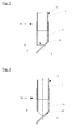
- FIG. 1 shows a level gauge 1, which operates on the radar principle.
- the level gauge 1 has in a rear area behind a wave adjuster 5, a signal generator and an evaluation, which are not shown in the present case.
- the signal generator is designed to emit electromagnetic wave packets in a length of about 1 ns and a frequency of about 26 GHz.
- Other typical frequencies used for level measurement are 5.8-6.3, 10, 24-27 or 75-83 GHz.
- the electromagnetic waves are coupled via the wave adjuster 5 in a waveguide 3, which is also referred to as a standpipe.
- the electromagnetic waves are guided in the waveguide 3 in the direction of the medium and at an interface between a medium and the overlying medium, in particular air or other gas, reflected. From a measurement of a transit time of the electromagnetic Wave packets can then be calculated a level within a container. In addition to reflections at the interface, ie the surface of the filling material, reflections are also produced at the end of the waveguide and at the container bottom.
- the level measuring device further comprises an adapter 10, on the front side, a reflector 13 is arranged.
- the reflector 13 may alternatively be arranged directly on the waveguide 3 for attachment to an adapter 10.
- the reflector 13 is inclined relative to a longitudinal axis L of the waveguide 3, which corresponds in the present embodiment, the axis of rotation of the cylindrically shaped waveguide 3, by an angle ⁇ .
- the angle ⁇ is chosen in the present embodiment, which also provides particularly good results, with 45 °, but may also deviate from this value.
- the reflector 13 shown in the present embodiment is substantially plate-shaped and dimensioned in size such that it has at least the surface of the projection of a cross section of the waveguide 3 to a corresponding angle ⁇ inclined surface. In this way it is achieved that all electromagnetic waves emerging from the waveguide on the front side by the reflector 13 and reflected in accordance with the applicable laws of reflection.
- the reflector 13 intersects an end face S of the waveguide in its diameter, so that 50% of the end face S are closed by the reflector 13 and in the remaining 50% between the end face S and the reflector 13, a lateral opening is formed.
- the proportion of the electromagnetic waves that are laterally reflected away from the waveguide 3, depends essentially on the angle ⁇ of the reflector 13 and on the size of the laterally resulting opening.
- the reflector 13 is, as shown in the present embodiment, attached to an outer wall of a mounting portion 11 of the adapter 10.
- the attachment portion 10 is formed cylindrically corresponding to the waveguide 3 and pushed over an outer periphery of the waveguide 3 and connected thereto, for example, by gluing or welding.
- the reflector 13 is also welded to the attachment portion 11.
- the mounting portion 11 is cut to the front at an angle of 45 °, so that there is an inclined at an angle of 45 ° contact surface for the reflector 13, to which the reflector 13 is also welded.
- FIGS. 2 and 3 show two further embodiments of adapters 10 according to the invention, wherein the reflector 13, the end face S according to the embodiment in FIG. 2 only 33% and according to the embodiment in FIG. 3 does not close.
- a section line of the end face S of the waveguide 3 respectively of the adapter 10 and the reflector 13 by 33% of the diameter of the End face S in the direction of the center shifted.
- the reflector 13 is arranged directly on a peripheral line of the end face S and supported only for mechanical stabilization by an extension of the adapter 10 and the waveguide 3, respectively. Seen from the end face S is thus an intersection x between the reflector 13 and the longitudinal axis L of the waveguide 3 and the adapter 10 always in front of the end face S.
- TEM waves ie. H. is linearly polarized electromagnetic waves, in which the electric and the magnetic field of the electromagnetic wave are perpendicular to each other and disappear in the propagation direction.
- FIG. 4 shows a schematic representation of echo curves at a level of 0%, that is, when the level is in the region of the open end of the waveguide 3.
- Curve 21 shows the echo which arises at the open end of a waveguide 3 according to the prior art, when this radiates into the free space, that is not in a container or tank.
- Curve 22 shows the echo that is generated when using a fill level measuring device according to the invention or when using a level gauge with an adapter according to the invention.
- Curve 23 shows the echo of a medium with a low dielectric constant (for example, ⁇ ⁇ 2.5), as is the case with oils, for example.
- Curve 24 shows the echo that arises at a container bottom when the waveguide 3 is mounted in a region near the container bottom and no reflector is provided according to the present invention.
- the inventive measures it is achieved that the electromagnetic waves do not impinge on the container bottom, but are deflected laterally and thus the bottom echo (curve 24) avoided and only the echo produced at the reflector (curve 22) is formed.
- the amplitude of the measurement signal (curve 23) in this range is significantly greater than the amplitude of the signal generated by the reflector (curve 22), so that measurements can be performed up to a fill level of approximately 0% compared to the prior art.
- FIG. 5 shows two error curves for level gauges with a 45 cm long waveguide. Plotted is the measurement error in mm with respect to the distance of the surface of the medium from the beginning of the waveguide 3, ie the exposed part of the waveguide 3rd
- Curve 25 shows the measurement error in a level measuring device 1 according to the prior art and curve 26 shows the measurement error in a fill level measuring device according to the invention.
- the measurement error in both measuring devices in the range of 0 to 34 cm in the range of + / - 5 mm. Due to the resulting bottom echo 24, the measurement error in the state-of-the-art level measuring device begins to jump sharply due to interferences, so that from a value of 34 cm, no measured values can be determined any longer.
- the measuring error continues to be in the range of + / - 5 mm even beyond 34 cm up to a value of 44 cm.
- an adapter 10 according to the present invention or with a level gauge with a reflector 13 according to the invention so that measurements can be carried out to the end of the waveguide 10 used.
Landscapes
- Physics & Mathematics (AREA)
- Electromagnetism (AREA)
- Thermal Sciences (AREA)
- Fluid Mechanics (AREA)
- General Physics & Mathematics (AREA)
- Measurement Of Levels Of Liquids Or Fluent Solid Materials (AREA)
- Length-Measuring Devices Using Wave Or Particle Radiation (AREA)
Priority Applications (3)
| Application Number | Priority Date | Filing Date | Title |
|---|---|---|---|
| EP12163195.6A EP2647971A1 (fr) | 2012-04-04 | 2012-04-04 | Appareil de mesure du niveau de remplissage et adaptateur doté d'un réflecteur |
| US13/795,759 US20140091962A1 (en) | 2012-04-04 | 2013-03-12 | Level gauge system and adaptor with reflector |
| CN 201310116210 CN103364051A (zh) | 2012-04-04 | 2013-04-03 | 物位测量装置及带反射器的适配器 |
Applications Claiming Priority (1)
| Application Number | Priority Date | Filing Date | Title |
|---|---|---|---|
| EP12163195.6A EP2647971A1 (fr) | 2012-04-04 | 2012-04-04 | Appareil de mesure du niveau de remplissage et adaptateur doté d'un réflecteur |
Publications (1)
| Publication Number | Publication Date |
|---|---|
| EP2647971A1 true EP2647971A1 (fr) | 2013-10-09 |
Family
ID=45929425
Family Applications (1)
| Application Number | Title | Priority Date | Filing Date |
|---|---|---|---|
| EP12163195.6A Withdrawn EP2647971A1 (fr) | 2012-04-04 | 2012-04-04 | Appareil de mesure du niveau de remplissage et adaptateur doté d'un réflecteur |
Country Status (3)
| Country | Link |
|---|---|
| US (1) | US20140091962A1 (fr) |
| EP (1) | EP2647971A1 (fr) |
| CN (1) | CN103364051A (fr) |
Cited By (1)
| Publication number | Priority date | Publication date | Assignee | Title |
|---|---|---|---|---|
| DE102021132030A1 (de) | 2021-12-06 | 2023-06-07 | Vega Grieshaber Kg | Radarsensoranordnung |
Families Citing this family (5)
| Publication number | Priority date | Publication date | Assignee | Title |
|---|---|---|---|---|
| DE102013214324A1 (de) * | 2013-07-22 | 2015-01-22 | Vega Grieshaber Kg | Radarfüllstandmessgerät mit einer Sicherheitseinrichtung |
| HUE028118T2 (en) * | 2013-08-14 | 2016-11-28 | Grieshaber Vega Kg | Radar beam diverting unit for charge level gauge |
| DE102013226778A1 (de) * | 2013-12-19 | 2015-06-25 | Vega Grieshaber Kg | Radarfüllstandsmessgerät |
| US10422682B2 (en) * | 2014-07-07 | 2019-09-24 | Vega Grieshaber Kg | Radar level gauge comprising a safety device |
| EP3483569B1 (fr) * | 2017-11-14 | 2021-08-25 | VEGA Grieshaber KG | Appareil de mesure de niveau de remplissage avec séparation galvanique dans le guide d'ondes |
Citations (3)
| Publication number | Priority date | Publication date | Assignee | Title |
|---|---|---|---|---|
| JPH10142029A (ja) * | 1996-11-08 | 1998-05-29 | Wire Device:Kk | レベル計 |
| WO2005031284A2 (fr) * | 2003-09-23 | 2005-04-07 | Endress+Hauser Gmbh+Co. Kg | Systeme de mesure de niveau dans un reservoir equipe d'un tuyau de sondage |
| US20100207807A1 (en) * | 2009-02-17 | 2010-08-19 | Gk Tech Star, Llc | Level gauge with positive level verifier |
Family Cites Families (8)
| Publication number | Priority date | Publication date | Assignee | Title |
|---|---|---|---|---|
| US6292131B1 (en) * | 2000-01-26 | 2001-09-18 | Ohmart - Vega, Inc. | Apparatus and method for liquid level measurement and content purity measurement in a sounding tube |
| US6795015B2 (en) * | 2003-01-29 | 2004-09-21 | Saab Rosemount Tank Radar Ab | Bottom reflector for a radar-based level gauge |
| DE102005042646A1 (de) * | 2005-09-07 | 2007-03-08 | Endress + Hauser Gmbh + Co. Kg | Vorrichtung zur Ermittlung und Überwachung des Füllstandes eines Mediums in einem Behälter |
| US7345622B2 (en) * | 2005-10-14 | 2008-03-18 | Saab Rosemount Tank Radar Ab | Two-mode radar level gauge system |
| US8059059B2 (en) * | 2008-05-29 | 2011-11-15 | Vivant Medical, Inc. | Slidable choke microwave antenna |
| DE102008029771A1 (de) * | 2008-06-25 | 2009-12-31 | Endress + Hauser Gmbh + Co. Kg | Anordnung zur Füllstandsmessung |
| US20100286687A1 (en) * | 2009-05-06 | 2010-11-11 | Ian Feldberg | Dual Energy Therapy Needle |
| US8872695B2 (en) * | 2011-06-14 | 2014-10-28 | Rosemount Tank Radar Ab | Guided wave radar level gauge system with dielectric constant compensation through multi-mode propagation |
-
2012
- 2012-04-04 EP EP12163195.6A patent/EP2647971A1/fr not_active Withdrawn
-
2013
- 2013-03-12 US US13/795,759 patent/US20140091962A1/en not_active Abandoned
- 2013-04-03 CN CN 201310116210 patent/CN103364051A/zh active Pending
Patent Citations (3)
| Publication number | Priority date | Publication date | Assignee | Title |
|---|---|---|---|---|
| JPH10142029A (ja) * | 1996-11-08 | 1998-05-29 | Wire Device:Kk | レベル計 |
| WO2005031284A2 (fr) * | 2003-09-23 | 2005-04-07 | Endress+Hauser Gmbh+Co. Kg | Systeme de mesure de niveau dans un reservoir equipe d'un tuyau de sondage |
| US20100207807A1 (en) * | 2009-02-17 | 2010-08-19 | Gk Tech Star, Llc | Level gauge with positive level verifier |
Cited By (1)
| Publication number | Priority date | Publication date | Assignee | Title |
|---|---|---|---|---|
| DE102021132030A1 (de) | 2021-12-06 | 2023-06-07 | Vega Grieshaber Kg | Radarsensoranordnung |
Also Published As
| Publication number | Publication date |
|---|---|
| CN103364051A (zh) | 2013-10-23 |
| US20140091962A1 (en) | 2014-04-03 |
Similar Documents
| Publication | Publication Date | Title |
|---|---|---|
| EP2647971A1 (fr) | Appareil de mesure du niveau de remplissage et adaptateur doté d'un réflecteur | |
| DE102012016120B4 (de) | Mikrowellenfenster und nach dem Radar-Prinzip arbeitendes Füllstandmesssystem | |
| EP2035790B1 (fr) | Dispositif de détermination et/ou de surveillance du niveau de remplissage d'une substance | |
| EP0834722B1 (fr) | Appareil de mesure de niveau à microondes | |
| EP0882957B1 (fr) | Procédé de mesure du niveau d'un matériau dans un réservoir suivant le principe radar | |
| EP2010872B1 (fr) | Système ultrasonore conçu pour mesurer le niveau d'un liquide dans un récipient | |
| DE202005008528U1 (de) | Messgerät der Prozessmesstechnik mit einer Parabolantenne | |
| WO2016139155A1 (fr) | Dispositif et procédé de mesure du diamètre et/ou de l'épaisseur de paroi d'une barre de coulée | |
| EP0668488A2 (fr) | Dispositif de mesure du niveau de remplissage d'un réservoir | |
| EP3017280B1 (fr) | Dispositif d'antenne pour appareil de mesure de niveau | |
| EP1619747A1 (fr) | Antenne parabolique de détecteur de niveau et détecteur de niveau comportant une antenne parabolique | |
| DE102011122346A1 (de) | Radareinrichtung für ein Kraftfahrzeug, Halter für ein Radargerät und Verfahren zum Herstellen eines Absorptionselements für ein Radargerät | |
| DE102012205640B4 (de) | Füllstandsgeber | |
| DE4419462A1 (de) | Berührungsloser Füllstandsmesser | |
| DE10051297A1 (de) | Füllstandsmeßgerät | |
| DE102011106568B4 (de) | Schwimmkörper zur Anzeige eines Füllstandes | |
| EP3084369B1 (fr) | Appareil de mesure de niveau à radar | |
| DE10109453A1 (de) | Vorrichtung zur Bestimmung und/oder Überwachung des Füllstands eines Füllguts in einem Behälter | |
| EP3535562A1 (fr) | Système de mesure de micro-ondes destiné à la détermination de la charge d'un écoulement biphasé | |
| EP1274973A2 (fr) | Dispositif de determination du niveau de remplissage d'un recipient avec un agent de remplissage | |
| DE102020106020A1 (de) | Füllstandsmessgerät | |
| DE102005044143A1 (de) | Radar-Füllstandsmessung mittels elektromagnetischer Verzögerungsleitung | |
| DE102013221213A1 (de) | Schwimmkörper und Anordnung zum Messen eines Füllstands | |
| WO2001096900A1 (fr) | Procede et dispositif d'amelioration de la stabilite a la temperature et de la resistance au vieillissement de mesureurs de niveau a radar a l'aide d'une reference mecanique | |
| DE102018101798B4 (de) | Hornantenne für ein Radarmessgerät und Radarmessgerät |
Legal Events
| Date | Code | Title | Description |
|---|---|---|---|
| PUAI | Public reference made under article 153(3) epc to a published international application that has entered the european phase |
Free format text: ORIGINAL CODE: 0009012 |
|
| AK | Designated contracting states |
Kind code of ref document: A1 Designated state(s): AL AT BE BG CH CY CZ DE DK EE ES FI FR GB GR HR HU IE IS IT LI LT LU LV MC MK MT NL NO PL PT RO RS SE SI SK SM TR |
|
| AX | Request for extension of the european patent |
Extension state: BA ME |
|
| STAA | Information on the status of an ep patent application or granted ep patent |
Free format text: STATUS: THE APPLICATION IS DEEMED TO BE WITHDRAWN |
|
| 18D | Application deemed to be withdrawn |
Effective date: 20140410 |