EP2647971A1 - Fill level measuring device and adapter with reflector - Google Patents
Fill level measuring device and adapter with reflector Download PDFInfo
- Publication number
- EP2647971A1 EP2647971A1 EP12163195.6A EP12163195A EP2647971A1 EP 2647971 A1 EP2647971 A1 EP 2647971A1 EP 12163195 A EP12163195 A EP 12163195A EP 2647971 A1 EP2647971 A1 EP 2647971A1
- Authority
- EP
- European Patent Office
- Prior art keywords
- reflector
- waveguide
- adapter
- measuring device
- level measuring
- Prior art date
- Legal status (The legal status is an assumption and is not a legal conclusion. Google has not performed a legal analysis and makes no representation as to the accuracy of the status listed.)
- Withdrawn
Links
Images

Classifications
-
- G—PHYSICS
- G01—MEASURING; TESTING
- G01F—MEASURING VOLUME, VOLUME FLOW, MASS FLOW OR LIQUID LEVEL; METERING BY VOLUME
- G01F23/00—Indicating or measuring liquid level or level of fluent solid material, e.g. indicating in terms of volume or indicating by means of an alarm
- G01F23/22—Indicating or measuring liquid level or level of fluent solid material, e.g. indicating in terms of volume or indicating by means of an alarm by measuring physical variables, other than linear dimensions, pressure or weight, dependent on the level to be measured, e.g. by difference of heat transfer of steam or water
- G01F23/28—Indicating or measuring liquid level or level of fluent solid material, e.g. indicating in terms of volume or indicating by means of an alarm by measuring physical variables, other than linear dimensions, pressure or weight, dependent on the level to be measured, e.g. by difference of heat transfer of steam or water by measuring the variations of parameters of electromagnetic or acoustic waves applied directly to the liquid or fluent solid material
- G01F23/284—Electromagnetic waves
Definitions
- the present invention relates to the field of level measurement and in particular the field of level measurement with radar, wherein for level measurement electromagnetic waves, which are guided by a waveguide, are used.
- Level measuring devices with a signal generator for generating electromagnetic waves and an elongate waveguide for guiding the generated electromagnetic waves are known from the prior art.
- Such fill level measuring devices are generally used for level measurement of liquids, wherein the waveguide is designed as a cylindrical tube into which the filling material, d. H. especially the liquid, penetrates.
- the emitted and guided in the waveguide electromagnetic waves are at least partially reflected, so that by means of a transit time measurement of the level of the medium can be determined within the waveguide.
- Such a level measuring device is particularly suitable for liquids, such as solvents or liquid gases and liquids with foaming and for products with low dielectric conductivity ⁇ .
- FIG. 4 23 shows the regular measuring signal, ie the reflection of the electromagnetic wave at the surface of the medium and with the bottom reflection in a prior art level indicator at a filling level of approximately 0%.
- the bottom reflection 24 completely covers the measurement signal 23, so that a detection of the measurement signal 23 is not possible.
- FIG. 5 is another negative effect shown in the prior art, in which occur in a level gauge with a 45 cm long waveguide, which is mounted just above the bottom of a tank, in the range between 34 cm and 40 cm interference between the measurement signal and the ground reflection , so that the detected signal starts to jump and therefore therefore a meaningful level measurement is no longer possible.
- a fill level measuring device has a signal generator for generating electromagnetic waves and an elongated waveguide for guiding the generated electromagnetic waves, wherein a reflector is arranged at the end of the waveguide.
- a reflector in the sense of this application means the arrangement of a reflecting surface in an angle deviating from the longitudinal axis of the waveguide.
- a reflector which is preferably plate-shaped and is arranged at the end of the waveguide such that the generated electromagnetic waves at the end of the waveguide not further in the direction of a bottom of a tank in which a level is to be determined escape, but of the reflector are laterally reflected away from the waveguide, it is achieved that the bottom echo is to a large extent and in the ideal case almost completely hidden.
- the remaining echo at the end of the waveguide, the proportion of the reflection, which is reflected by the reflector in the waveguide, can be detected.
- this component is reduced in such a way that it has a lower amplitude than a measurement signal recorded in this region, so that due to the reflector a measured value determination can also take place in the end region of the waveguide.
- the electromagnetic signal which is reflected laterally for example in the direction of a container wall, is still detected by the level measuring device, it lies outside the permissible measuring range due to the increased transit time and can thus be completely blanked out in the generation of measured values.
- the waveguide is designed as a tube, preferably as a cylindrical tube.
- the reflector should preferably be oriented at an angle of less than 75 °, preferably between 35 ° and 55 ° to the longitudinal axis of the waveguide. Particularly good results are achieved with an orientation of the reflector at an angle of 45 ° to the longitudinal axis of the waveguide.
- the reflector arranged on the waveguide may be made of any material which at least partially reflects electromagnetic waves. Possible materials are accordingly plastics with an increased dielectric constant and preferably metals.
- a preferred embodiment of the reflector provides that the reflector is metallized at least partially metallic, preferably at least on a surface facing the waveguide, for example vapor-deposited or printed.
- a mechanically and chemically particularly resistant variant of the reflector is achieved when the reflector is made of a sheet metal, preferably of a steel sheet of a chemical inert steel, for example of a stainless steel.
- the reflector can also be made of a steel by welding particularly easy connection between the reflector and the waveguide in an embodiment of the waveguide.
- a particularly simple variant for producing this connection is given by an arrangement of the reflector and an outer wall of the waveguide.
- the reflector and the waveguide In addition to the possibility of welding the reflector to the waveguide, in particular with other materials, it is also possible to bond the reflector and the waveguide to one another or to produce another mechanical connection.
- An increase in the mechanical stability of the arrangement can be achieved if the reflector with the waveguide not only punctiform, but is connected to a line-shaped portion of the outer wall of the waveguide. In this way it can be avoided that the reflector is easily separated from the waveguide under mechanical stress, e.g. aborts.
- Such a linear attachment of the reflector to the waveguide can for example be achieved in that the waveguide is cut to length in the portion of the outer wall to which the reflector is attached at the angle at which the reflector is aligned.
- an end face of the outer wall is created at the end of the waveguide, which is aligned according to the orientation of the reflector.
- the reflector can thus be connected over the entire end face in this area with the waveguide.
- the reflector is preferably arranged on the waveguide such that an intersection of the longitudinal axis of the waveguide, that is arranged in connection with the present application of an axis of symmetry of the waveguide, in particular a rotation axis of the waveguide with the reflector in front of the waveguide is.
- An arrangement of the point of intersection in front of the waveguide means that this intersection in particular does not lie within the waveguide, but rather lies at least on a plane aligned at the level of the end of the waveguide perpendicular to the longitudinal axis of the waveguide.
- the reflector is arranged such that it closes an end face of the waveguide to at most 50%.
- the reflector closes the end face of the waveguide to at most 30% and more preferably not.
- the radiated electromagnetic waves are so-called TEM waves, in which the electrical and the magnetic component are pairwise orthogonal to the propagation direction of the electromagnetic wave. Compared for arrangements in which the normal vector is oriented differently, improvements of 4 to 6 dB have been achieved.
- An improvement of level measuring devices of the prior art, which operate on the principle of waveguide guided electromagnetic wave can be achieved by an adapter having a mounting portion for the end-side attachment of the adapter to an elongated waveguide of the level gauge, wherein a reflector is provided.
- a reflector is provided.
- the above definition for the attachment of a reflector also applies to the adapter according to the invention.
- the attachment portion is preferably formed corresponding to the waveguide, so that the adapter can be attached to the waveguide, for example, and connected to this by welding or gluing or by mechanical jamming.
- the attachment portion of the adapter is cylindrical.
- the adapter can be arranged in a favorable orientation for the respective application on the waveguide. For example, it is thus possible to align the adapter such that waves reflected by the reflector have to travel as far as possible to the next container wall. But it is also possible, as already shown above, to align the adapter suitably to the vibration levels of the electrical and the magnetic component of the electromagnetic field, so that a particularly good suppression of reflections takes place. An alignment in the direction of a distant container wall can then be achieved for example by a corresponding arrangement of the level gauge in the container.
- an adapter according to the invention can be achieved if this is made for example of plastic.
- the adapter is preferably at least partially metallic, for example metallized on the surface at least in the area of the reflector.
- a particularly stable embodiment of the adapter can be achieved if it is made of a sheet metal, preferably a steel sheet. Particularly in the manufacture of the adapter from a steel sheet, a stable mechanical connection of the adapter to a waveguide which is likewise made of steel can be produced particularly simply, for example by welding. In principle, however, a bond or other mechanical connection of the components is possible.
- the reflector is preferably aligned with the adapter at an angle of less than 75 °, between 35 ° and 55 °, to the longitudinal axis of the attachment portion. Particularly good results were achieved at an angle of 45 °.
- the reflector is preferably attached to an outer wall of the attachment portion of the adapter.
- the attachment is preferably carried out in a linear section, since in this way a particularly stable connection can be achieved.
- the attachment portion in the portion of the outer wall to which the reflector is attached is cut to length at the angle at which the reflector is aligned.
- An intersection of the longitudinal axis of the mounting portion with the reflector is preferably in front of the mounting portion, as in this way it is achieved that at the preferred orientation of the reflector at an angle of 45 ° to the longitudinal axis of the mounting portion at least 50% of the radiating electromagnetic waves in an area outside the attachment portion or the waveguide are reflected.
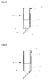
- FIG. 1 shows a level gauge 1, which operates on the radar principle.
- the level gauge 1 has in a rear area behind a wave adjuster 5, a signal generator and an evaluation, which are not shown in the present case.
- the signal generator is designed to emit electromagnetic wave packets in a length of about 1 ns and a frequency of about 26 GHz.
- Other typical frequencies used for level measurement are 5.8-6.3, 10, 24-27 or 75-83 GHz.
- the electromagnetic waves are coupled via the wave adjuster 5 in a waveguide 3, which is also referred to as a standpipe.
- the electromagnetic waves are guided in the waveguide 3 in the direction of the medium and at an interface between a medium and the overlying medium, in particular air or other gas, reflected. From a measurement of a transit time of the electromagnetic Wave packets can then be calculated a level within a container. In addition to reflections at the interface, ie the surface of the filling material, reflections are also produced at the end of the waveguide and at the container bottom.
- the level measuring device further comprises an adapter 10, on the front side, a reflector 13 is arranged.
- the reflector 13 may alternatively be arranged directly on the waveguide 3 for attachment to an adapter 10.
- the reflector 13 is inclined relative to a longitudinal axis L of the waveguide 3, which corresponds in the present embodiment, the axis of rotation of the cylindrically shaped waveguide 3, by an angle ⁇ .
- the angle ⁇ is chosen in the present embodiment, which also provides particularly good results, with 45 °, but may also deviate from this value.
- the reflector 13 shown in the present embodiment is substantially plate-shaped and dimensioned in size such that it has at least the surface of the projection of a cross section of the waveguide 3 to a corresponding angle ⁇ inclined surface. In this way it is achieved that all electromagnetic waves emerging from the waveguide on the front side by the reflector 13 and reflected in accordance with the applicable laws of reflection.
- the reflector 13 intersects an end face S of the waveguide in its diameter, so that 50% of the end face S are closed by the reflector 13 and in the remaining 50% between the end face S and the reflector 13, a lateral opening is formed.
- the proportion of the electromagnetic waves that are laterally reflected away from the waveguide 3, depends essentially on the angle ⁇ of the reflector 13 and on the size of the laterally resulting opening.
- the reflector 13 is, as shown in the present embodiment, attached to an outer wall of a mounting portion 11 of the adapter 10.
- the attachment portion 10 is formed cylindrically corresponding to the waveguide 3 and pushed over an outer periphery of the waveguide 3 and connected thereto, for example, by gluing or welding.
- the reflector 13 is also welded to the attachment portion 11.
- the mounting portion 11 is cut to the front at an angle of 45 °, so that there is an inclined at an angle of 45 ° contact surface for the reflector 13, to which the reflector 13 is also welded.
- FIGS. 2 and 3 show two further embodiments of adapters 10 according to the invention, wherein the reflector 13, the end face S according to the embodiment in FIG. 2 only 33% and according to the embodiment in FIG. 3 does not close.
- a section line of the end face S of the waveguide 3 respectively of the adapter 10 and the reflector 13 by 33% of the diameter of the End face S in the direction of the center shifted.
- the reflector 13 is arranged directly on a peripheral line of the end face S and supported only for mechanical stabilization by an extension of the adapter 10 and the waveguide 3, respectively. Seen from the end face S is thus an intersection x between the reflector 13 and the longitudinal axis L of the waveguide 3 and the adapter 10 always in front of the end face S.
- TEM waves ie. H. is linearly polarized electromagnetic waves, in which the electric and the magnetic field of the electromagnetic wave are perpendicular to each other and disappear in the propagation direction.
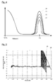
- FIG. 4 shows a schematic representation of echo curves at a level of 0%, that is, when the level is in the region of the open end of the waveguide 3.
- Curve 21 shows the echo which arises at the open end of a waveguide 3 according to the prior art, when this radiates into the free space, that is not in a container or tank.
- Curve 22 shows the echo that is generated when using a fill level measuring device according to the invention or when using a level gauge with an adapter according to the invention.
- Curve 23 shows the echo of a medium with a low dielectric constant (for example, ⁇ ⁇ 2.5), as is the case with oils, for example.
- Curve 24 shows the echo that arises at a container bottom when the waveguide 3 is mounted in a region near the container bottom and no reflector is provided according to the present invention.
- the inventive measures it is achieved that the electromagnetic waves do not impinge on the container bottom, but are deflected laterally and thus the bottom echo (curve 24) avoided and only the echo produced at the reflector (curve 22) is formed.
- the amplitude of the measurement signal (curve 23) in this range is significantly greater than the amplitude of the signal generated by the reflector (curve 22), so that measurements can be performed up to a fill level of approximately 0% compared to the prior art.
- FIG. 5 shows two error curves for level gauges with a 45 cm long waveguide. Plotted is the measurement error in mm with respect to the distance of the surface of the medium from the beginning of the waveguide 3, ie the exposed part of the waveguide 3rd
- Curve 25 shows the measurement error in a level measuring device 1 according to the prior art and curve 26 shows the measurement error in a fill level measuring device according to the invention.
- the measurement error in both measuring devices in the range of 0 to 34 cm in the range of + / - 5 mm. Due to the resulting bottom echo 24, the measurement error in the state-of-the-art level measuring device begins to jump sharply due to interferences, so that from a value of 34 cm, no measured values can be determined any longer.
- the measuring error continues to be in the range of + / - 5 mm even beyond 34 cm up to a value of 44 cm.
- an adapter 10 according to the present invention or with a level gauge with a reflector 13 according to the invention so that measurements can be carried out to the end of the waveguide 10 used.
Landscapes
- Physics & Mathematics (AREA)
- Electromagnetism (AREA)
- Thermal Sciences (AREA)
- Fluid Mechanics (AREA)
- General Physics & Mathematics (AREA)
- Measurement Of Levels Of Liquids Or Fluent Solid Materials (AREA)
- Length-Measuring Devices Using Wave Or Particle Radiation (AREA)
Abstract
Description
Die vorliegende Erfindung betrifft den Bereich der Füllstandmesstechnik und insbesondere den Bereich der Füllstandmesstechnik mit Radar, wobei zur Füllstandmessung elektromagnetische Wellen, die von einem Hohlleiter geführt sind, verwendet werden.The present invention relates to the field of level measurement and in particular the field of level measurement with radar, wherein for level measurement electromagnetic waves, which are guided by a waveguide, are used.
Aus dem Stand der Technik sind Füllstandmessgeräte mit einem Signalgenerator zur Erzeugung von elektromagnetischen Wellen und einem langgestreckten Hohlleiter zur Führung der erzeugten elektromagnetischen Wellen bekannt. Derartige Füllstandmessgeräte werden in der Regel zur Füllstandmessung von Flüssigkeiten verwendet, wobei der Hohlleiter als zylindrisches Rohr ausgebildet ist, in das das Füllgut, d. h. insbesondere die Flüssigkeit, eindringt. An einer Grenzfläche des Füllmediums werden die ausgesendeten und in dem Hohlleiter geführten elektromagnetischen Wellen wenigstens teilweise reflektiert, so dass mit Hilfe einer Laufzeitmessung der Füllstand des Mediums innerhalb des Hohlleiters ermittelt werden kann.Level measuring devices with a signal generator for generating electromagnetic waves and an elongate waveguide for guiding the generated electromagnetic waves are known from the prior art. Such fill level measuring devices are generally used for level measurement of liquids, wherein the waveguide is designed as a cylindrical tube into which the filling material, d. H. especially the liquid, penetrates. At an interface of the filling medium, the emitted and guided in the waveguide electromagnetic waves are at least partially reflected, so that by means of a transit time measurement of the level of the medium can be determined within the waveguide.
Ein derartiges Füllstandmessgerät eignet sich besonders für Flüssigkeiten, beispielsweise Lösungsmittel oder Flüssiggase sowie Flüssigkeiten mit Schaumbildung sowie für Füllgüter mit niedriger dielektrischer Leitfähigkeit ε.Such a level measuring device is particularly suitable for liquids, such as solvents or liquid gases and liquids with foaming and for products with low dielectric conductivity ε.
Bei den aus dem Stand der Technik bekannten Füllstandmessgeräten besteht das Problem, dass bei einem Füllstand nahe Null, d. h. wenn eine Reflexion des Messsignals im Bereich eines einem Behälterboden naheliegenden Endes des Hohlleiters erfolgt, ein Bodenecho, d. h. eine Reflexion der elektromagnetischen Welle an dem meist metallischen Boden des Behälters erfolgt, das Messsignal überdeckt, so dass keine Ermittlung des Füllstands mehr möglich ist.In the level measuring devices known from the prior art, there is the problem that at a level close to zero, that is, when a reflection of the measurement signal in the region of an end of the waveguide near a container bottom takes place, a bottom echo, ie a reflection of the electromagnetic wave at the most metallic Bottom of the container, the measurement signal covers, so that no determination of the level is possible.
In
In
Es ist die Aufgabe der vorliegenden Erfindung, ein Füllstandmessgerät zur Verfügung zu stellen, das die Nachteile aus dem Stand der Technik nicht aufweist. Es ist ferner eine Aufgabe der vorliegenden Erfindung eine Möglichkeit zur Verfügung zu stellen, mit der die oben beschriebenen Nachteile bei Füllstandmessgeräten aus dem Stand der Technik beseitigt werden können.It is the object of the present invention to provide a level measuring device which does not have the disadvantages of the prior art. It is a further object of the present invention to provide a means by which the above described drawbacks of prior art level gauges can be eliminated.
Diese Aufgaben werden durch ein Füllstandmessgerät mit den Merkmalen des Patentanspruchs 1 sowie einen Adapter für ein Füllstandmessgerät mit den Merkmalen des Patentanspruchs 12 gelöst.These objects are achieved by a level gauge with the features of
Ein erfindungsgemäßes Füllstandmessgerät weist einen Signalgenerator zur Erzeugung elektromagnetischer Wellen und einen langgestreckten Hohlleiter zur Führung der erzeugten elektromagnetischen Wellen auf, wobei an dem Hohlleiter endseitig ein Reflektor angeordnet ist. Das Vorsehen eines Reflektors im Sinne dieser Anmeldung bedeutet, die Anordnung einer reflektierenden Fläche in einem von der Längsachse des Hohlleiters abweichenden Winkel.A fill level measuring device according to the invention has a signal generator for generating electromagnetic waves and an elongated waveguide for guiding the generated electromagnetic waves, wherein a reflector is arranged at the end of the waveguide. The provision of a reflector in the sense of this application means the arrangement of a reflecting surface in an angle deviating from the longitudinal axis of the waveguide.
Durch das Vorsehen eines Reflektors, der bevorzugt plattenförmig ausgebildet ist und am Ende des Hohlleiters derart angeordnet ist , dass die erzeugten elektromagnetischen Wellen am Ende des Hohlleiters nicht weiter in Richtung eines Bodens eines Tanks, in dem ein Füllstand ermittelt werden soll, austreten, sondern von dem Reflektor seitlich von dem Hohlleiter weg reflektiert werden, wird erreicht, dass das Bodenecho zu einem großen Teil und im Idealfall annähernd vollständig ausgeblendet wird. Als verbleibendes Echo am Ende des Hohlleiters wird der Anteil der Reflexion, der von dem Reflektor in den Hohlleiter zurückgeworfen wird, detektiert werden. Dieser Anteil ist jedoch so reduziert, dass er eine geringere Amplitude als ein in diesem Bereich aufgenommenes Messsignal aufweist, so dass aufgrund des Reflektors auch im Endbereich des Hohlleiters eine Messwertermittlung stattfinden kann. Das seitlich, beispielsweise in Richtung einer Behälterwand reflektierte elektromagnetische Signal wird zwar weiterhin von dem Füllstandmessgerät erfasst, liegt aber aufgrund der erhöhten Laufzeit außerhalb des zulässigen Messbereiches und kann damit bei der Messwerterzeugung vollständig ausgeblendet werden.By providing a reflector, which is preferably plate-shaped and is arranged at the end of the waveguide such that the generated electromagnetic waves at the end of the waveguide not further in the direction of a bottom of a tank in which a level is to be determined escape, but of the reflector are laterally reflected away from the waveguide, it is achieved that the bottom echo is to a large extent and in the ideal case almost completely hidden. The remaining echo at the end of the waveguide, the proportion of the reflection, which is reflected by the reflector in the waveguide, can be detected. However, this component is reduced in such a way that it has a lower amplitude than a measurement signal recorded in this region, so that due to the reflector a measured value determination can also take place in the end region of the waveguide. Although the electromagnetic signal which is reflected laterally, for example in the direction of a container wall, is still detected by the level measuring device, it lies outside the permissible measuring range due to the increased transit time and can thus be completely blanked out in the generation of measured values.
Typischerweise ist der Hohlleiter als Rohr, bevorzugt als Zylinderrohr ausgebildet.Typically, the waveguide is designed as a tube, preferably as a cylindrical tube.
Es hat sich gezeigt, dass der Reflektor bevorzugt in einem Winkel kleiner als 75°, bevorzugt zwischen 35° und 55° zu der Längsachse des Hohlleiters ausgerichtet sein sollte. Besonders gute Ergebnisse werden bei einer Ausrichtung des Reflektors in einem Winkel von 45° zur Längsachse des Hohlleiters erreicht.It has been found that the reflector should preferably be oriented at an angle of less than 75 °, preferably between 35 ° and 55 ° to the longitudinal axis of the waveguide. Particularly good results are achieved with an orientation of the reflector at an angle of 45 ° to the longitudinal axis of the waveguide.
Bei einer Ausrichtung des Reflektors in einem Winkel von 45° zur Längsachse des Hohlleiters wird erreicht, dass ein relativ großer Anteil des elektromagnetischen Signals aus dem Bereich des Hohlleiters heraus reflektiert wird.With an alignment of the reflector at an angle of 45 ° to the longitudinal axis of the waveguide is achieved that a relatively large portion of the electromagnetic signal from the region of the waveguide is reflected out.
Grundsätzlich kann der an dem Hohlleiter angeordnete Reflektor aus jedem Material bestehen, das elektromagnetische Wellen wenigstens teilweise reflektiert. Mögliche Materialien sind dementsprechend Kunststoffe mit einer erhöhten Dielektrizitätszahl sowie bevorzugt Metalle.In principle, the reflector arranged on the waveguide may be made of any material which at least partially reflects electromagnetic waves. Possible materials are accordingly plastics with an increased dielectric constant and preferably metals.
Eine bevorzugte Ausgestaltung des Reflektors sieht vor, dass der Reflektor wenigstens teilweise metallisch, bevorzugt wenigstens auf einer dem Hohlleiter zugewandten Oberfläche metallisiert, beispielsweise bedampft oder bedruckt ist.A preferred embodiment of the reflector provides that the reflector is metallized at least partially metallic, preferably at least on a surface facing the waveguide, for example vapor-deposited or printed.
Eine mechanisch und chemisch besonders widerstandsfähige Variante des Reflektors wird erreicht, wenn der Reflektor aus einem Blech, bevorzugt aus einem Stahlblech aus einem chemischen inerten Stahl, beispielsweise aus einem Edelstahl gefertigt ist.A mechanically and chemically particularly resistant variant of the reflector is achieved when the reflector is made of a sheet metal, preferably of a steel sheet of a chemical inert steel, for example of a stainless steel.
Bei einer derartigen Ausgestaltung des Reflektors kann außerdem bei einer Ausbildung des Hohlleiters ebenfalls aus einem Stahl durch Verschweißen besonders einfach eine Verbindung zwischen dem Reflektor und dem Hohlleiter hergestellt werden.In such an embodiment of the reflector can also be made of a steel by welding particularly easy connection between the reflector and the waveguide in an embodiment of the waveguide.
Eine besonders einfache Variante zur Herstellung dieser Verbindung ist durch eine Anordnung des Reflektors und einer Außenwandung des Hohlleiters gegeben. Neben der Möglichkeit, den Reflektor mit dem Hohlleiter zu verschweißen besteht, insbesondere bei anderen Materialien, auch die Möglichkeit den Reflektor und den Hohlleiter miteinander zu verkleben oder eine andere mechanische Verbindung herzustellen.A particularly simple variant for producing this connection is given by an arrangement of the reflector and an outer wall of the waveguide. In addition to the possibility of welding the reflector to the waveguide, in particular with other materials, it is also possible to bond the reflector and the waveguide to one another or to produce another mechanical connection.
Eine Erhöhung der mechanischen Stabilität der Anordnung kann erreicht werden, wenn der Reflektor mit dem Hohlleiter nicht nur punktförmig, sondern an einem linienförmigen Abschnitt der Außenwandung des Hohlleiters verbunden ist. Auf diese Weise kann vermieden werden, dass der Reflektor bei mechanischer Beanspruchung allzu leicht von dem Hohlleiter getrennt wird, z.B. abbricht.An increase in the mechanical stability of the arrangement can be achieved if the reflector with the waveguide not only punctiform, but is connected to a line-shaped portion of the outer wall of the waveguide. In this way it can be avoided that the reflector is easily separated from the waveguide under mechanical stress, e.g. aborts.
Eine solche linienförmige Befestigung des Reflektors an dem Hohlleiter kann beispielsweise dadurch erreicht werden, dass der Hohlleiter in dem Abschnitt der Außenwandung, an dem der Reflektor befestigt ist, in dem Winkel abgelängt ist, in dem der Reflektor ausgerichtet ist.Such a linear attachment of the reflector to the waveguide can for example be achieved in that the waveguide is cut to length in the portion of the outer wall to which the reflector is attached at the angle at which the reflector is aligned.
Auf diese Weise wird am Ende des Hohlleiters eine Stirnfläche der Außenwandung geschaffen, die entsprechend der Ausrichtung des Reflektors ausgerichtet ist. Der Reflektor kann damit über die komplette Stirnfläche in diesem Bereich mit dem Hohlleiter verbunden werden.In this way, an end face of the outer wall is created at the end of the waveguide, which is aligned according to the orientation of the reflector. The reflector can thus be connected over the entire end face in this area with the waveguide.
Der Reflektor ist bevorzugt derart an dem Hohlleiter angeordnet, dass ein Schnittpunkt der Längsachse des Hohlleiters, das bedeutet im Zusammenhang mit der vorliegenden Anmeldung einer Symmetrieachse des Hohlleiters, insbesondere einer Rotationsachse des Hohlleiters mit dem Reflektor vor dem Hohlleiter angeordnet ist. Eine Anordnung des Schnittpunktes vor dem Hohlleiter bedeutet, dass dieser Schnittpunkt insbesondere nicht innerhalb des Hohlleiters liegt, sondern wenigstens auf einer auf Höhe des Endes des Hohlleiters senkrecht zur Längsachse des Hohlleiters ausgerichteten Ebene liegt.The reflector is preferably arranged on the waveguide such that an intersection of the longitudinal axis of the waveguide, that is arranged in connection with the present application of an axis of symmetry of the waveguide, in particular a rotation axis of the waveguide with the reflector in front of the waveguide is. An arrangement of the point of intersection in front of the waveguide means that this intersection in particular does not lie within the waveguide, but rather lies at least on a plane aligned at the level of the end of the waveguide perpendicular to the longitudinal axis of the waveguide.
Bei einer Ausrichtung des Reflektors in einem Winkel von 45° zu der Längsachse des Hohlleiters bedeutet dies, dass wenigstens 50 % der Fläche des Reflektors derart angeordnet sind, dass einstrahlende elektromagnetische Wellen in einen Bereich außerhalb des Hohlleiters reflektiert werden.With an orientation of the reflector at an angle of 45 ° to the longitudinal axis of the waveguide, this means that at least 50% of the surface of the reflector are arranged such that radiating electromagnetic waves are reflected in a region outside the waveguide.
Bevorzugt ist der Reflektor derart angeordnet, dass er eine Stirnfläche des Hohlleiters zu höchstens 50 % verschließt. Bevorzugt verschließt der Reflektor die Stirnfläche des Hohlleiters zu höchstens 30 % und weiter bevorzugt nicht.Preferably, the reflector is arranged such that it closes an end face of the waveguide to at most 50%. Preferably, the reflector closes the end face of the waveguide to at most 30% and more preferably not.
Ein Verschließen der Stirnfläche des Hohlleiters bedeutet im Zusammenhang mit dieser Anmeldung, dass der Reflektor durch seine Anbringung eine imaginäre Stirnfläche, die senkrecht zur Längsachse des Hohlleiters liegt um den angegebenen Anteil reduziert, d. h. dass der entsprechende Anteil der Stirnfläche entfällt und in diesem Bereich der Reflektor angeordnet ist.Closing the end face of the waveguide means in connection with this application that the reflector by its attachment an imaginary end face, which is perpendicular to the longitudinal axis of the waveguide is reduced by the specified proportion, d. H. that the corresponding proportion of the end face is omitted and the reflector is arranged in this area.
Besonders gute Ergebnisse werden erzielt, wenn ein Normalenvektor des Reflektors in einer Schwingungsebene des magnetischen Feldes der abgestrahlten elektromagnetischen Wellen liegt.Particularly good results are achieved when a normal vector of the reflector lies in a plane of oscillation of the magnetic field of the radiated electromagnetic waves.
Bei den abgestrahlten elektromagnetischen Wellen handelt es sich um sogenannte TEM-Wellen, bei denen die elektrische und die magnetische Komponente paarweise orthogonal zur Ausbreitungsrichtung der elektromagnetischen Welle sind. Im Vergleich zu Anordnungen, bei denen der Normalenvektor anders orientiert ist, wurden so Verbesserungen von 4 bis 6 dB erreicht.The radiated electromagnetic waves are so-called TEM waves, in which the electrical and the magnetic component are pairwise orthogonal to the propagation direction of the electromagnetic wave. Compared for arrangements in which the normal vector is oriented differently, improvements of 4 to 6 dB have been achieved.
Eine Verbesserung von Füllstandsmessgeräten aus dem Stand der Technik, die nach dem Prinzip der Hohlleiter geführten elektromagnetischen Welle arbeiten, kann durch einen Adapter erreicht werden, der einen Befestigungsabschnitt zur endseitigen Befestigung des Adapters an einem langgestreckten Hohlleiter des Füllstandsmessgerätes aufweist, wobei ein Reflektor vorgesehen ist. Die oben genannte Definition für die Anbringung eines Reflektors gilt auch für den erfindungsgemäßen Adapter.An improvement of level measuring devices of the prior art, which operate on the principle of waveguide guided electromagnetic wave can be achieved by an adapter having a mounting portion for the end-side attachment of the adapter to an elongated waveguide of the level gauge, wherein a reflector is provided. The above definition for the attachment of a reflector also applies to the adapter according to the invention.
Der Befestigungsabschnitt ist bevorzugt korrespondierend zu dem Hohlleiter ausgebildet, sodass der Adapter auf den Hohlleiter beispielsweise aufgesteckt und mit diesem durch Verschweißen oder Verkleben oder durch mechanisches Verklemmen verbunden werden kann.The attachment portion is preferably formed corresponding to the waveguide, so that the adapter can be attached to the waveguide, for example, and connected to this by welding or gluing or by mechanical jamming.
Für zylindrisch ausgebildete Hohlleiter ist es bevorzugt, wenn der Befestigungsabschnitt des Adapters zylindrisch ausgebildet ist. Auf diese Weise kann der Adapter in einer günstigen Orientierung für den jeweiligen Einsatzzweck an dem Hohlleiter angeordnet werden. Beispielsweise ist es so möglich, den Adapter derart auszurichten, dass von dem Reflektor reflektierte Wellen eine möglichst weite Strecke zur nächsten Behälterwand zurückzulegen haben. Es ist aber auch möglich, wie bereits oben dargestellt, den Adapter geeignet zu den Schwingungsebenen der elektrischen und der magnetischen Komponente des elektromagnetischen Feldes auszurichten, sodass eine besonders gute Unterdrückung von Reflektionen stattfindet. Eine Ausrichtung in Richtung einer weit entfernten Behälterwand kann dann beispielsweise durch eine entsprechende Anordnung des Füllstandmessgerätes in dem Behälter erreicht werden.For cylindrically shaped waveguides, it is preferred if the attachment portion of the adapter is cylindrical. In this way, the adapter can be arranged in a favorable orientation for the respective application on the waveguide. For example, it is thus possible to align the adapter such that waves reflected by the reflector have to travel as far as possible to the next container wall. But it is also possible, as already shown above, to align the adapter suitably to the vibration levels of the electrical and the magnetic component of the electromagnetic field, so that a particularly good suppression of reflections takes place. An alignment in the direction of a distant container wall can then be achieved for example by a corresponding arrangement of the level gauge in the container.
Eine besonders günstige Herstellung eines erfindungsgemäßen Adapters kann erreicht werden, wenn dieser beispielsweise aus Kunststoff gefertigt wird. Bevorzugt ist der Adapter jedoch wenigstens teilweise metallisch, beispielsweise wenigstens im Bereich des Reflektors oberflächlich metallisiert.A particularly favorable production of an adapter according to the invention can be achieved if this is made for example of plastic. However, the adapter is preferably at least partially metallic, for example metallized on the surface at least in the area of the reflector.
Eine besonders stabile Ausgestaltung des Adapters kann erreicht werden, wenn dieser aus einem Blech, bevorzugt einem Stahlblech gefertigt ist. Insbesondere bei der Fertigung des Adapters aus einem Stahlblech kann besonders einfach eine stabile mechanische Verbindung des Adapters mit einem Hohlleiter der ebenfalls aus Stahl gefertigt ist, beispielsweise durch Verschweißen hergestellt werden. Grundsätzlich ist aber auch eine Verklebung oder eine andere mechanische Verbindung der Komponenten möglich.A particularly stable embodiment of the adapter can be achieved if it is made of a sheet metal, preferably a steel sheet. Particularly in the manufacture of the adapter from a steel sheet, a stable mechanical connection of the adapter to a waveguide which is likewise made of steel can be produced particularly simply, for example by welding. In principle, however, a bond or other mechanical connection of the components is possible.
Der Reflektor ist an dem Adapter bevorzugt in einem Winkel kleiner als 75°, zwischen 35° und 55°, zu der Längsachse des Befestigungsabschnittes ausgerichtet. Besonders gute Ergebnisse wurden bei einem Winkel von 45° erreicht. Durch eine derartige Ausrichtung des Reflektors relativ zu dem Befestigungsabschnitt des Adapters wird erreicht, dass bei einem Aufstecken des Adapters auf den Hohlleiter eines Füllstandmessgerätes eine Ausrichtung des Reflektors relativ zu dem Hohlleiter des Füllstandmessgerätes erreicht wird.The reflector is preferably aligned with the adapter at an angle of less than 75 °, between 35 ° and 55 °, to the longitudinal axis of the attachment portion. Particularly good results were achieved at an angle of 45 °. By such an orientation of the reflector relative to the mounting portion of the adapter is achieved that when attaching the adapter to the waveguide of a level measuring device alignment of the reflector is achieved relative to the waveguide of the level measuring device.
Der Reflektor ist bevorzugt an einer Außenwandung des Befestigungsabschnittes des Adapters befestigt. Die Befestigung erfolgt bevorzugt in einem linienförmigen Abschnitt, da auf diese Weise eine besonders stabile Verbindung erreicht werden kann.The reflector is preferably attached to an outer wall of the attachment portion of the adapter. The attachment is preferably carried out in a linear section, since in this way a particularly stable connection can be achieved.
Um die Stabilität der Befestigung des Reflektors an dem Befestigungsabschnitt weiter zu erhöhen, ist der Befestigungsabschnitt in dem Abschnitt der Außenwandung, an dem der Reflektor befestigt ist, in dem Winkel abgelängt, in dem der Reflektor ausgerichtet ist.In order to further increase the stability of the attachment of the reflector to the attachment portion, the attachment portion in the portion of the outer wall to which the reflector is attached is cut to length at the angle at which the reflector is aligned.
Ein Schnittpunkt der Längsachse des Befestigungsabschnittes mit dem Reflektor liegt bevorzugt vor dem Befestigungsabschnitt, da auf diese Weise erreicht wird, dass bei der bevorzugten Ausrichtung des Reflektors in einem Winkel von 45° zur Längsachse des Befestigungsabschnitts wenigstens 50% der einstrahlenden elektromagnetischen Wellen in einem Bereich außerhalb des Befestigungsabschnittes bzw. des Hohlleiters reflektiert werden.An intersection of the longitudinal axis of the mounting portion with the reflector is preferably in front of the mounting portion, as in this way it is achieved that at the preferred orientation of the reflector at an angle of 45 ° to the longitudinal axis of the mounting portion at least 50% of the radiating electromagnetic waves in an area outside the attachment portion or the waveguide are reflected.
Versuche haben gezeigt, dass besonders gute Ergebnisse erzielt werden, wenn der Reflektor derart angeordnet ist, dass er eine Stirnfläche des Befestigungsabschnittes zu höchstens 50% verschließt. Besonders gute Ergebnisse werden erreicht, wenn der Reflektor die Stirnfläche zu höchstens 33 % und weiter bevorzugt nicht verschließt.Experiments have shown that particularly good results are achieved when the reflector is arranged so that it closes an end face of the attachment portion to a maximum of 50%. Particularly good results are achieved when the reflector does not close the end face to a maximum of 33%, and more preferably not.
Die oben angegebenen Definitionen bezüglich der Anordnung des Schnittpunktes des Reflektors mit der Längsachse des Hohlleiters sowie betreffend das Verschließen der Stirnfläche des Hohlleiters sind mutatis mutandis auf den Adapter anzuwenden.The definitions given above with respect to the arrangement of the point of intersection of the reflector with the longitudinal axis of the waveguide and with respect to the closing of the end face of the waveguide are mutatis mutandis to apply to the adapter.
Die Erfindung wird nachfolgend anhand von drei Ausführungsbeispielen unter Bezugnahme auf die beigefügten Figuren eingehend erläutert. Es zeigen:
Figur 1- ein erfindungsgemäßes Füllstandmessgerät mit einem erfindungsgemäßen Adapter in einer ersten Ausführungsform,
Figur 2- ein Standrohr eines Füllstandmessgerätes mit einem erfindungsgemäßen Adapter in einer ersten Ausführung,
Figur 3- ein Füllstandmessgerät mit einem erfindungsgemäße Adapter gemäß einer dritten Ausführung,
- Figur 4
- schematisch dargestellte Echokurven und
Figur 5- ein Vergleich der Abweichungen eines Messwertes vom tatsächlichen Füllstand bei Füllstandmessgeräten gemäß dem Stand der Technik sowie der vorliegenden Erfindung.
- FIG. 1
- a fill level measuring device according to the invention with an adapter according to the invention in a first embodiment,
- FIG. 2
- a standpipe of a level measuring device with an adapter according to the invention in a first embodiment,
- FIG. 3
- a level gauge with an adapter according to the invention according to a third embodiment,
- FIG. 4
- schematically illustrated echo curves and
- FIG. 5
- a comparison of the deviations of a measured value from the actual level in level measurement devices according to the prior art and the present invention.
Das Füllstandmessgerät 1 weist in einem rückseitigen Bereich hinter einem Wellenanpasser 5 einen Signalgenerator sowie eine Auswerteelektronik auf, die vorliegend nicht dargestellt sind. Der Signalgenerator ist geeignet ausgebildet, elektromagnetische Wellenpakete in einer Länge von etwa 1 ns sowie einer Frequenz von etwa 26 GHz auszusenden. Weitere typische, für die Füllstandmessung eingesetzte Frequenzen liegen bei 5.8-6.3, 10, 24 - 27 oder 75 - 83 GHz.The
Die elektromagnetischen Wellen werden über den Wellenanpasser 5 in einen Hohlleiter 3 eingekoppelt, der auch als Standrohr bezeichnet wird. Die elektromagnetische Wellen werden in dem Hohlleiter 3 in Richtung des Füllguts geführt und an einer Grenzefläche zwischen einem Füllgut und dem darüber befindlichen Medium, insbesondere Luft oder einem anderen Gas, reflektiert. Aus einer Messung einer Laufzeit der elektromagnetischen Wellenpakete kann dann ein Füllstand innerhalb eines Behälters errechnet werden. Zusätzlich zu Reflektionen an der Grenzfläche, d.h. der Oberfläche des Füllgutes, werden auch Reflexionen am Ende des Hohlleiters sowie am Behälterboden hervorgerufen. Im Stand der Technik führen insbesondere die Bodenreflektoren dazu, dass bei bodennah montierten Rohrantennen eine Messung im Endbereich des Hohlleiters 3 nicht mehr möglich ist, da das Bodenecho mit seiner extrem hohen Amplitude ein Messsignal, das von der Oberfläche des Messguts erzeugt wird, vollständig überlagert. Auf die entsprechenden Effekte wird zu einem späteren Zeitpunkt noch näher eingegangen.The electromagnetic waves are coupled via the
Das erfindungsgemäße Füllstandmessgerät weist weiter einen Adapter 10 auf, an dem vorderseitig ein Reflektor 13 angeordnet ist. Der Reflektor 13 kann alternativ zur Befestigung an einen Adapter 10 auch direkt an dem Hohlleiter 3 angeordnet sein.The level measuring device according to the invention further comprises an
Der Reflektor 13 ist relativ zu einer Längsachse L des Hohlleiters 3, die im vorliegenden Ausführungsbeispiel der Rotationsachse des zylindrisch ausgebildeten Hohlleiters 3 entspricht, um einen Winkel α geneigt. Der Winkel α ist im vorliegenden Ausführungsbeispiel, das auch besonders gute Ergebnisse liefert, mit 45° gewählt, kann aber auch von diesem Wert abweichen.The
Der im vorliegenden Ausführungsbeispiel gezeigte Reflektor 13 ist im Wesentlichen plattenförmig ausgebildet und in seiner Größe derart dimensioniert, dass er wenigstens die Fläche der Projektion eines Querschnitts des Hohlleiters 3 auf eine entsprechend dem Winkel α geneigte Fläche aufweist. Auf diese Weise wird erreicht, dass sämtliche elektromagnetischen Wellen, die aus dem Hohlleiter vorderseitig austreten durch den Reflektor 13 erfasst und entsprechend der anzuwendenden Reflexionsgesetze reflektiert werden.The
Im vorliegenden Ausführungsbeispiel schneidet der Reflektor 13 eine Stirnfläche S des Hohlleiters in ihrem Durchmesser, sodass 50 % der Stirnfläche S von dem Reflektor 13 verschlossen sind und im Bereich der übrigen 50% zwischen der Stirnfläche S und dem Reflektor 13 eine seitliche Öffnung entsteht. Der Anteil der elektromagnetischen Wellen, die aus dem Hohlleiter 3 heraus seitlich wegreflektiert werden, hängt im Wesentlichen vom Winkel α des Reflektors 13 sowie von der Größe der seitlich entstehenden Öffnung ab. Der Reflektor 13 ist, wie im vorliegenden Ausführungsbeispiel dargestellt, an einer Außenwandung eines Befestigungsabschnitts 11 des Adapters 10 befestigt. Der Befestigungsabschnitt 10 ist korrespondierend zu dem Hohlleiter 3 zylindrisch ausgeformt und über einen Außenumfang des Hohlleiters 3 geschoben und mit diesem beispielsweise durch Verkleben oder Verschweißen verbunden.In the present embodiment, the
Der Reflektor 13 ist an dem Befestigungsabschnitt 11 ebenfalls angeschweißt. Im vorliegenden Ausführungsbeispiel ist der Befestigungsabschnitt 11 vorderseitig in einem Winkel von 45° abgelängt, sodass sich eine im Winkel von 45° geneigte Anlagefläche für den Reflektor 13 ergibt, an welcher der Reflektor 13 ebenfalls angeschweißt ist.The
In den
Besonders gute Ergebnisse wurden erzielt, wenn ein Normalenvektor N des Reflektors 13 in der Schwingungsebene des magnetischen Anteils der abgestrahlten elektromagnetischen Wellen liegt. Um dies gewährleisten zu können, ist natürlich Voraussetzung, dass es sich bei den abgestrahlten elektromagnetischen Wellen um sogenannte TEM-Wellen, d. h. linear polarisiert elektromagnetische Wellen handelt, bei denen das elektrische und das magnetische Feld der elektromagnetischen Welle senkrecht zueinander stehen und in Ausbreitungsrichtung verschwinden.Particularly good results have been achieved when a normal vector N of the
Kurve 22 zeigt das Echo, das bei Verwendung eines erfindungsgemäßen Füllstandmessgerätes bzw. bei Verwendung eines Füllstandmessgerätes mit einem erfindungsgemäßen Adapter erzeugt wird.
Kurve 23 zeigt das Echo eines Mediums mit kleiner Dielektrizitätszahl (beispielsweise ε < 2,5) wie dies beispielsweise bei Ölen der Fall ist.
Kurve 24 zeigt das Echo, das an einem Behälterboden entsteht, wenn der Hohlleiter 3 bis in einem Bereich nahe des Behälterbodens montiert ist und kein Reflektor gemäß der vorliegenden Erfindung vorgesehen ist.
Wie
Durch die erfindungsgemäße Maßnahmen wird erreicht, dass die elektromagnetischen Wellen nicht auf den Behälterboden auftreffen, sondern seitlich abgelenkt werden und damit das Bodenecho (Kurve 24) vermieden und lediglich das an dem Reflektor entstehenden Echo (Kurve 22) entsteht. Die Amplitude des Messsignals (Kurve 23) ist in diesem Bereich aber deutlich größer als die Amplitude des von dem Reflektor erzeugten Signals (Kurve 22), sodass im Vergleich zum Stand der Technik Messungen bis zu einem Füllstand von annähernd 0 % durchgeführt werden können.The inventive measures it is achieved that the electromagnetic waves do not impinge on the container bottom, but are deflected laterally and thus the bottom echo (curve 24) avoided and only the echo produced at the reflector (curve 22) is formed. However, the amplitude of the measurement signal (curve 23) in this range is significantly greater than the amplitude of the signal generated by the reflector (curve 22), so that measurements can be performed up to a fill level of approximately 0% compared to the prior art.
Kurve 25 zeigt den Messfehler bei einem Füllstandmessgerät 1 gemäß dem Stand der Technik und Kurve 26 zeigt den Messfehler bei einem erfindungsgemäßen Füllstandmessgerät.
Wie
Bei dem Füllstandmessgerät gemäß der vorliegenden Erfindung ist zu erkennen, dass der Messfehler auch über 34 cm hinaus bis zu einem Wert von 44 cm weiterhin im Bereich von + / - 5 mm liegt. Mit einem Adapter 10 gemäß der vorliegenden Erfindung bzw. mit einem Füllstandmessgerät mit einem erfindungsgemäßen Reflektor 13 können damit Messungen bis ans Ende des verwendeten Hohlleiters 10 durchgeführt werden.In the level measuring device according to the present invention, it can be seen that the measuring error continues to be in the range of + / - 5 mm even beyond 34 cm up to a value of 44 cm. With an
- 11
- Füllstandmessgerätlevel meter
- 22
- Antenneantenna
- 33
- Hohlleiter / StandrohrWaveguide / standpipe
- 55
- WellenanpasserWellenanpasser
- 77
- Außenwandungouter wall
- 1010
- Adapteradapter
- 1111
- Befestigungsabschnittattachment section
- 1313
- Reflektorreflector
- 2121
- Reflexion offenes RohrReflection open pipe
- 2222
- Reflexion mit ReflektorReflection with reflector
- 2323
- Messsignalmeasuring signal
- 2424
- Bodenreflexion ohne ReflektorFloor reflection without reflector
- 2525
- Fehler SdTError SdT
- 2626
- Fehler ErfError erf
- αα
- Winkelangle
- NN
- Normalenvektornormal vector
- SS
- Stirnflächeface
- LL
- Längsachselongitudinal axis
- xx
- Schnittpunktintersection
Claims (20)
dadurch gekennzeichnet, dass an dem Hohlleiter (3) endseitig ein Reflektor (13) angeordnet ist.Level gauge (1) having an electromagnetic wave signal generator and an elongated waveguide (3) for guiding the generated electromagnetic waves,
characterized in that on the waveguide (3) end a reflector (13) is arranged.
dadurch gekennzeichnet, dass der Hohlleiter (3) als Rohr, bevorzugt als Zylinderrohr, ausgebildet ist.Level measuring device (1) according to one of the preceding claims,
characterized in that the waveguide (3) as a tube, is preferably formed as a cylindrical tube.
dadurch gekennzeichnet, dass der Reflektor (13) in einem vorgegebenen Winkel (α) kleiner als 75°, bevorzugt zwischen 35° und 55°, bevorzugt 45°, zu einer Längsachse (L) des Hohlleiters (3) ausgerichtet ist.Level measuring device (1) according to one of the preceding claims,
characterized in that the reflector (13) at a predetermined angle (α) is less than 75 °, preferably between 35 ° and 55 °, preferably 45 °, to a longitudinal axis (L) of the waveguide (3) is aligned.
dadurch gekennzeichnet, dass der Reflektor (13) wenigstens teilweise metallisch ist.Level measuring device (1) according to one of the preceding claims,
characterized in that the reflector (13) is at least partially metallic.
dadurch gekennzeichnet, dass der Reflektor (13) aus einem Blech, bevorzugt aus einem Stahlblech gefertigt ist.Level measuring device (1) according to one of the preceding claims,
characterized in that the reflector (13) is made of a sheet metal, preferably of a steel sheet.
dadurch gekennzeichnet, dass der Reflektor (13) an einer Außenwandung (7) des Hohlleiters (3) angeordnet ist.Level measuring device (1) according to one of the preceding claims,
characterized in that the reflector (13) on an outer wall (7) of the waveguide (3) is arranged.
dadurch gekennzeichnet, dass der Reflektor (13) an einem linienförmigen Abschnitt der Außenwandung (7) des Hohlleiters (3) befestigt ist.Level gauge (1) according to claim 6,
characterized in that the reflector (13) is attached to a line-shaped portion of the outer wall (7) of the waveguide (3).
dadurch gekennzeichnet, dass der Hohlleiter (3) in dem Abschnitt der Außenwandung (7), an dem der Reflektor (13) befestigt ist, in dem Winkel (α) abgelängt ist, in dem der Reflektor (13) ausgerichtet ist.Level gauge (1) according to claim 7,
characterized in that the waveguide (3) in the portion of the outer wall (7) to which the reflector (13) is fixed, is cut to length at the angle (α) in which the reflector (13) is aligned.
dadurch gekennzeichnet, dass ein Schnittpunkt der Längsachse (L) des Hohlleiters (3) mit dem Reflektor (13) vor dem Hohlleiter (3) angeordnet ist.Level measuring device (1) according to one of the preceding claims,
characterized in that an intersection of the longitudinal axis (L) of the waveguide (3) with the reflector (13) in front of the waveguide (3) is arranged.
dadurch gekennzeichnet, dass der Reflektor (13) derart angeordnet ist, dass er eine Stirnfläche des Hohlleiters (3) zu höchstens 50% verschließt, bevorzugt zu höchstens 33% und weiter bevorzugt 0% verschließt.Level measuring device (1) according to one of the preceding claims,
characterized in that the reflector (13) is arranged such that it closes an end face of the waveguide (3) to at most 50%, preferably to at most 33% and more preferably closes 0%.
dadurch gekennzeichnet, dass ein Normalenvektor des Reflektors (13) in einer Schwingungsebene des magnetischen Feldes der abgestrahlten elektromagnetischen Welle liegt.Level measuring device (1) according to one of the preceding claims,
characterized in that a normal vector of the reflector (13) lies in a plane of vibration of the magnetic field of the radiated electromagnetic wave.
dadurch gekennzeichnet, dass der Adapter (10) einen Befestigungsabschnitt (11) zur endseitigen Befestigung des Adapters (10) an einem langgestreckten Hohlleiter (3) des Füllstandmessgerätes (1) aufweist,
ein Reflektor (13) vorgesehen ist und
der Reflektor (13) in einem vorgegebenen Winkel (α) kleiner als 75° zu einer Längsachse (L) des Befestigungsabschnitts (11) angeordnet ist.Adapter (10) for a level gauge (1) operating on the principle of a waveguide-guided electromagnetic wave,
characterized in that the adapter (10) has a fastening portion (11) for fastening the end of the adapter (10) to an elongate waveguide (3) of the level measuring device (1),
a reflector (13) is provided and
the reflector (13) at a predetermined angle (α) is less than 75 ° to a longitudinal axis (L) of the mounting portion (11) is arranged.
dadurch gekennzeichnet, dass der Befestigungsabschnitt (11) zylindrisch ausgebildet ist.Adapter (10) according to claim 12,
characterized in that the fastening portion (11) is cylindrical.
dadurch gekennzeichnet, dass der Adapter (10) wenigstens teilweise metallisch, bevorzugt aus einem Blech, insbesondere einem Stahlblech, gefertigt ist.Adapter (10) according to one of claims 12 or 13,
characterized in that the adapter (10) is at least partially metallic, preferably made of a metal sheet, in particular a steel sheet.
dadurch gekennzeichnet, dass der Reflektor (13) in einem Winkel(α) zwischen 35° und 55°, bevorzugt 45°, zu der Längsachse (L) des Befestigungsabschnitts (11) ausgerichtet ist.Adapter (10) according to one of claims 12 to 14,
characterized in that the reflector (13) at an angle (α) between 35 ° and 55 °, preferably 45 °, to the longitudinal axis (L) of the mounting portion (11) is aligned.
dadurch gekennzeichnet, dass der Reflektor (13) an einer Außenwandung (7) des Befestigungsabschnitts (11) angeordnet ist.Adapter (10) according to one of claims 12 to 15,
characterized in that the reflector (13) on an outer wall (7) of the fastening portion (11) is arranged.
dadurch gekennzeichnet, dass der Reflektor (13) an einem linienförmigen Abschnitt der Außenwandung (7) des Befestigungsabschnittes (11) befestigt ist.Adapter (10) according to one of claims 12 to 16,
characterized in that the reflector (13) is attached to a line-shaped portion of the outer wall (7) of the attachment portion (11).
dadurch gekennzeichnet, dass der Befestigungsabschnitt (11) in dem Abschnitt der Außenwandung (7), an dem der Reflektor (13) befestigt ist, in dem Winkel (α) abgelängt ist, in dem der Reflektor (13) ausgerichtet ist.Adapter (10) according to one of claims 12 to 17,
characterized in that the fixing portion (11) in the portion of the outer wall (7) to which the reflector (13) is fixed is cut to length at the angle (α) in which the reflector (13) is aligned.
dadurch gekennzeichnet, dass ein Schnittpunkt der Längsachse (L) des Befestigungsabschnittes (11) mit dem Reflektor (13) vor dem Befestigungsabschnitt (11) angeordnet ist.Adapter (10) according to one of claims 12 to 18,
characterized in that an intersection of the longitudinal axis (L) of the attachment portion (11) with the reflector (13) is arranged in front of the attachment portion (11).
dadurch gekennzeichnet, dass der Reflektor (13) derart angeordnet ist, dass er eine Stirnfläche des Hohlleiters (3) zu höchstens 50% verschließt, bevorzugt zu höchstens 33% und weiter bevorzugt 0% verschließt.Adapter (10) according to one of the preceding claims,
characterized in that the reflector (13) is arranged such that it closes an end face of the waveguide (3) to at most 50%, preferably to at most 33% and more preferably closes 0%.
Priority Applications (3)
| Application Number | Priority Date | Filing Date | Title |
|---|---|---|---|
| EP12163195.6A EP2647971A1 (en) | 2012-04-04 | 2012-04-04 | Fill level measuring device and adapter with reflector |
| US13/795,759 US20140091962A1 (en) | 2012-04-04 | 2013-03-12 | Level gauge system and adaptor with reflector |
| CN 201310116210 CN103364051A (en) | 2012-04-04 | 2013-04-03 | Material level measuring device and adapter with reflector |
Applications Claiming Priority (1)
| Application Number | Priority Date | Filing Date | Title |
|---|---|---|---|
| EP12163195.6A EP2647971A1 (en) | 2012-04-04 | 2012-04-04 | Fill level measuring device and adapter with reflector |
Publications (1)
| Publication Number | Publication Date |
|---|---|
| EP2647971A1 true EP2647971A1 (en) | 2013-10-09 |
Family
ID=45929425
Family Applications (1)
| Application Number | Title | Priority Date | Filing Date |
|---|---|---|---|
| EP12163195.6A Withdrawn EP2647971A1 (en) | 2012-04-04 | 2012-04-04 | Fill level measuring device and adapter with reflector |
Country Status (3)
| Country | Link |
|---|---|
| US (1) | US20140091962A1 (en) |
| EP (1) | EP2647971A1 (en) |
| CN (1) | CN103364051A (en) |
Cited By (1)
| Publication number | Priority date | Publication date | Assignee | Title |
|---|---|---|---|---|
| DE102021132030A1 (en) | 2021-12-06 | 2023-06-07 | Vega Grieshaber Kg | radar sensor arrangement |
Families Citing this family (5)
| Publication number | Priority date | Publication date | Assignee | Title |
|---|---|---|---|---|
| DE102013214324A1 (en) * | 2013-07-22 | 2015-01-22 | Vega Grieshaber Kg | Radar level gauge with a safety device |
| HUE028118T2 (en) * | 2013-08-14 | 2016-11-28 | Grieshaber Vega Kg | Radar beam deflection unit for a fill level radar |
| DE102013226778A1 (en) * | 2013-12-19 | 2015-06-25 | Vega Grieshaber Kg | Radar level transmitter |
| US10422682B2 (en) * | 2014-07-07 | 2019-09-24 | Vega Grieshaber Kg | Radar level gauge comprising a safety device |
| EP3483569B1 (en) * | 2017-11-14 | 2021-08-25 | VEGA Grieshaber KG | Fill level measuring device with galvanic isolation in waveguide |
Citations (3)
| Publication number | Priority date | Publication date | Assignee | Title |
|---|---|---|---|---|
| JPH10142029A (en) * | 1996-11-08 | 1998-05-29 | Wire Device:Kk | Level gauge |
| WO2005031284A2 (en) * | 2003-09-23 | 2005-04-07 | Endress+Hauser Gmbh+Co. Kg | Arrangement for measuring the filling level in a tank equipped with a sounding pipe |
| US20100207807A1 (en) * | 2009-02-17 | 2010-08-19 | Gk Tech Star, Llc | Level gauge with positive level verifier |
Family Cites Families (8)
| Publication number | Priority date | Publication date | Assignee | Title |
|---|---|---|---|---|
| US6292131B1 (en) * | 2000-01-26 | 2001-09-18 | Ohmart - Vega, Inc. | Apparatus and method for liquid level measurement and content purity measurement in a sounding tube |
| US6795015B2 (en) * | 2003-01-29 | 2004-09-21 | Saab Rosemount Tank Radar Ab | Bottom reflector for a radar-based level gauge |
| DE102005042646A1 (en) * | 2005-09-07 | 2007-03-08 | Endress + Hauser Gmbh + Co. Kg | Device for detecting and monitoring the level of a medium in a container |
| US7345622B2 (en) * | 2005-10-14 | 2008-03-18 | Saab Rosemount Tank Radar Ab | Two-mode radar level gauge system |
| US8059059B2 (en) * | 2008-05-29 | 2011-11-15 | Vivant Medical, Inc. | Slidable choke microwave antenna |
| DE102008029771A1 (en) * | 2008-06-25 | 2009-12-31 | Endress + Hauser Gmbh + Co. Kg | Arrangement for level measurement |
| US20100286687A1 (en) * | 2009-05-06 | 2010-11-11 | Ian Feldberg | Dual Energy Therapy Needle |
| US8872695B2 (en) * | 2011-06-14 | 2014-10-28 | Rosemount Tank Radar Ab | Guided wave radar level gauge system with dielectric constant compensation through multi-mode propagation |
-
2012
- 2012-04-04 EP EP12163195.6A patent/EP2647971A1/en not_active Withdrawn
-
2013
- 2013-03-12 US US13/795,759 patent/US20140091962A1/en not_active Abandoned
- 2013-04-03 CN CN 201310116210 patent/CN103364051A/en active Pending
Patent Citations (3)
| Publication number | Priority date | Publication date | Assignee | Title |
|---|---|---|---|---|
| JPH10142029A (en) * | 1996-11-08 | 1998-05-29 | Wire Device:Kk | Level gauge |
| WO2005031284A2 (en) * | 2003-09-23 | 2005-04-07 | Endress+Hauser Gmbh+Co. Kg | Arrangement for measuring the filling level in a tank equipped with a sounding pipe |
| US20100207807A1 (en) * | 2009-02-17 | 2010-08-19 | Gk Tech Star, Llc | Level gauge with positive level verifier |
Cited By (1)
| Publication number | Priority date | Publication date | Assignee | Title |
|---|---|---|---|---|
| DE102021132030A1 (en) | 2021-12-06 | 2023-06-07 | Vega Grieshaber Kg | radar sensor arrangement |
Also Published As
| Publication number | Publication date |
|---|---|
| CN103364051A (en) | 2013-10-23 |
| US20140091962A1 (en) | 2014-04-03 |
Similar Documents
| Publication | Publication Date | Title |
|---|---|---|
| EP2647971A1 (en) | Fill level measuring device and adapter with reflector | |
| DE102012016120B4 (en) | Microwave windows and radar-based level measurement system | |
| EP2035790B1 (en) | Apparatus for determining and/or monitoring the level of a medium | |
| EP0834722B1 (en) | Microwave level measuring apparatus | |
| EP0882957B1 (en) | Method for material level measurement in a container according to the radar principle | |
| EP2010872B1 (en) | Ultrasound device for measuring the level of a liquid in a container | |
| DE202005008528U1 (en) | Process measuring instrument with a parabolic antenna | |
| WO2016139155A1 (en) | Device and method for measuring the diameter and/or the wall thickness of a strand | |
| EP0668488A2 (en) | Device for measuring the filling level of a container | |
| EP3017280B1 (en) | Antenna assembly for a fill-level measuring device | |
| EP1619747A1 (en) | Level gauge parabolic antenna and filling level gauge having a parabolic antenna | |
| DE102011122346A1 (en) | Radar device for a motor vehicle, holder for a radar device and method for producing an absorption element for a radar device | |
| DE102012205640B4 (en) | level sensor | |
| DE4419462A1 (en) | Contactless level meter | |
| DE10051297A1 (en) | Microwave level measurement device has microwave generator, transmit and receive antennas, reception and evaluation circuit that determines level from transition time of microwaves | |
| DE102011106568B4 (en) | Float to indicate a level | |
| EP3084369B1 (en) | Radar-operated level gauge | |
| DE10109453A1 (en) | Device for determining and / or monitoring the level of a product in a container | |
| EP3535562A1 (en) | Microwave measuring arrangement for determining the loading of a two-phase flow | |
| EP1274973A2 (en) | Device for determining the level of contents in a container | |
| DE102020106020A1 (en) | Level measuring device | |
| DE102005044143A1 (en) | Filling medium e.g. water, level measurement device for use in chemical industry, has line arrangement for guiding measurement serving electromagnetic waves with propagation characteristics, and designed as electromagnetic delay line | |
| DE102013221213A1 (en) | Float and arrangement for measuring a level | |
| WO2001096900A1 (en) | Method and device for improving the temperature stability and resistance to ageing of radar level meters using a mechanical reference | |
| DE102018101798B4 (en) | Horn antenna for a radar gauge and radar gauge |
Legal Events
| Date | Code | Title | Description |
|---|---|---|---|
| PUAI | Public reference made under article 153(3) epc to a published international application that has entered the european phase |
Free format text: ORIGINAL CODE: 0009012 |
|
| AK | Designated contracting states |
Kind code of ref document: A1 Designated state(s): AL AT BE BG CH CY CZ DE DK EE ES FI FR GB GR HR HU IE IS IT LI LT LU LV MC MK MT NL NO PL PT RO RS SE SI SK SM TR |
|
| AX | Request for extension of the european patent |
Extension state: BA ME |
|
| STAA | Information on the status of an ep patent application or granted ep patent |
Free format text: STATUS: THE APPLICATION IS DEEMED TO BE WITHDRAWN |
|
| 18D | Application deemed to be withdrawn |
Effective date: 20140410 |