EP2646323B1 - Contenant transportable pour les marchandises en vrac et procédé permettant de le constituer - Google Patents
Contenant transportable pour les marchandises en vrac et procédé permettant de le constituer Download PDFInfo
- Publication number
- EP2646323B1 EP2646323B1 EP11793977.7A EP11793977A EP2646323B1 EP 2646323 B1 EP2646323 B1 EP 2646323B1 EP 11793977 A EP11793977 A EP 11793977A EP 2646323 B1 EP2646323 B1 EP 2646323B1
- Authority
- EP
- European Patent Office
- Prior art keywords
- bulk goods
- transportable container
- slip frame
- frame former
- bag
- Prior art date
- Legal status (The legal status is an assumption and is not a legal conclusion. Google has not performed a legal analysis and makes no representation as to the accuracy of the status listed.)
- Active
Links
- 238000000034 method Methods 0.000 title claims description 49
- 238000004806 packaging method and process Methods 0.000 claims description 58
- 238000009826 distribution Methods 0.000 claims description 10
- 230000004044 response Effects 0.000 claims description 10
- 238000007493 shaping process Methods 0.000 claims description 10
- 229920002379 silicone rubber Polymers 0.000 claims description 2
- 230000007246 mechanism Effects 0.000 description 24
- 238000012546 transfer Methods 0.000 description 18
- 239000000463 material Substances 0.000 description 12
- 239000004033 plastic Substances 0.000 description 10
- 229920003023 plastic Polymers 0.000 description 10
- 239000003415 peat Substances 0.000 description 9
- 230000036961 partial effect Effects 0.000 description 7
- 239000008187 granular material Substances 0.000 description 6
- 235000013339 cereals Nutrition 0.000 description 5
- 230000008901 benefit Effects 0.000 description 4
- 235000013305 food Nutrition 0.000 description 4
- 238000003466 welding Methods 0.000 description 4
- 239000002023 wood Substances 0.000 description 4
- 230000009969 flowable effect Effects 0.000 description 3
- 239000007788 liquid Substances 0.000 description 3
- 238000004891 communication Methods 0.000 description 2
- 230000007423 decrease Effects 0.000 description 2
- 230000003247 decreasing effect Effects 0.000 description 2
- 230000003993 interaction Effects 0.000 description 2
- 239000005022 packaging material Substances 0.000 description 2
- 229920000642 polymer Polymers 0.000 description 2
- 230000001737 promoting effect Effects 0.000 description 2
- 230000009467 reduction Effects 0.000 description 2
- 230000002829 reductive effect Effects 0.000 description 2
- 239000004576 sand Substances 0.000 description 2
- 239000000126 substance Substances 0.000 description 2
- 238000011144 upstream manufacturing Methods 0.000 description 2
- 241000251468 Actinopterygii Species 0.000 description 1
- 235000000832 Ayote Nutrition 0.000 description 1
- 235000009854 Cucurbita moschata Nutrition 0.000 description 1
- 240000001980 Cucurbita pepo Species 0.000 description 1
- 235000009804 Cucurbita pepo subsp pepo Nutrition 0.000 description 1
- 241000287828 Gallus gallus Species 0.000 description 1
- 241001465754 Metazoa Species 0.000 description 1
- 229920000426 Microplastic Polymers 0.000 description 1
- 239000004677 Nylon Substances 0.000 description 1
- 241000238413 Octopus Species 0.000 description 1
- 240000007594 Oryza sativa Species 0.000 description 1
- 235000007164 Oryza sativa Nutrition 0.000 description 1
- 239000004809 Teflon Substances 0.000 description 1
- 229920006362 Teflon® Polymers 0.000 description 1
- 241000209140 Triticum Species 0.000 description 1
- 235000021307 Triticum Nutrition 0.000 description 1
- 230000004888 barrier function Effects 0.000 description 1
- 239000011324 bead Substances 0.000 description 1
- 239000004568 cement Substances 0.000 description 1
- 238000004140 cleaning Methods 0.000 description 1
- 239000011248 coating agent Substances 0.000 description 1
- 238000000576 coating method Methods 0.000 description 1
- 230000001427 coherent effect Effects 0.000 description 1
- 238000013461 design Methods 0.000 description 1
- 239000003814 drug Substances 0.000 description 1
- 210000005069 ears Anatomy 0.000 description 1
- 230000003670 easy-to-clean Effects 0.000 description 1
- 235000013399 edible fruits Nutrition 0.000 description 1
- 230000000694 effects Effects 0.000 description 1
- 239000003337 fertilizer Substances 0.000 description 1
- 239000012847 fine chemical Substances 0.000 description 1
- 239000011521 glass Substances 0.000 description 1
- 239000003292 glue Substances 0.000 description 1
- 235000011868 grain product Nutrition 0.000 description 1
- -1 gravel Substances 0.000 description 1
- 229920001903 high density polyethylene Polymers 0.000 description 1
- 239000004700 high-density polyethylene Substances 0.000 description 1
- 230000003100 immobilizing effect Effects 0.000 description 1
- 230000000670 limiting effect Effects 0.000 description 1
- 229920001684 low density polyethylene Polymers 0.000 description 1
- 239000004702 low-density polyethylene Substances 0.000 description 1
- 238000012423 maintenance Methods 0.000 description 1
- 235000013372 meat Nutrition 0.000 description 1
- 235000013622 meat product Nutrition 0.000 description 1
- 239000002184 metal Substances 0.000 description 1
- 238000012986 modification Methods 0.000 description 1
- 230000004048 modification Effects 0.000 description 1
- 239000002991 molded plastic Substances 0.000 description 1
- 229920001778 nylon Polymers 0.000 description 1
- 238000012856 packing Methods 0.000 description 1
- 239000002985 plastic film Substances 0.000 description 1
- 229920006255 plastic film Polymers 0.000 description 1
- 230000008569 process Effects 0.000 description 1
- 235000015136 pumpkin Nutrition 0.000 description 1
- 235000021067 refined food Nutrition 0.000 description 1
- 235000009566 rice Nutrition 0.000 description 1
- 238000007142 ring opening reaction Methods 0.000 description 1
- 239000011435 rock Substances 0.000 description 1
- 238000012163 sequencing technique Methods 0.000 description 1
- 239000007787 solid Substances 0.000 description 1
- 238000003860 storage Methods 0.000 description 1
- 239000004753 textile Substances 0.000 description 1
- 235000013311 vegetables Nutrition 0.000 description 1
- 239000011800 void material Substances 0.000 description 1
Images


Classifications
-
- B—PERFORMING OPERATIONS; TRANSPORTING
- B65—CONVEYING; PACKING; STORING; HANDLING THIN OR FILAMENTARY MATERIAL
- B65B—MACHINES, APPARATUS OR DEVICES FOR, OR METHODS OF, PACKAGING ARTICLES OR MATERIALS; UNPACKING
- B65B43/00—Forming, feeding, opening or setting-up containers or receptacles in association with packaging
- B65B43/42—Feeding or positioning bags, boxes, or cartons in the distended, opened, or set-up state; Feeding preformed rigid containers, e.g. tins, capsules, glass tubes, glasses, to the packaging position; Locating containers or receptacles at the filling position; Supporting containers or receptacles during the filling operation
- B65B43/54—Means for supporting containers or receptacles during the filling operation
- B65B43/60—Means for supporting containers or receptacles during the filling operation rotatable
- B65B43/62—Means for supporting containers or receptacles during the filling operation rotatable about an axis located at the filling position, e.g. the axis of the container or receptacle
-
- B—PERFORMING OPERATIONS; TRANSPORTING
- B65—CONVEYING; PACKING; STORING; HANDLING THIN OR FILAMENTARY MATERIAL
- B65B—MACHINES, APPARATUS OR DEVICES FOR, OR METHODS OF, PACKAGING ARTICLES OR MATERIALS; UNPACKING
- B65B1/00—Packaging fluent solid material, e.g. powders, granular or loose fibrous material, loose masses of small articles, in individual containers or receptacles, e.g. bags, sacks, boxes, cartons, cans, or jars
- B65B1/02—Machines characterised by the incorporation of means for making the containers or receptacles
-
- B—PERFORMING OPERATIONS; TRANSPORTING
- B65—CONVEYING; PACKING; STORING; HANDLING THIN OR FILAMENTARY MATERIAL
- B65B—MACHINES, APPARATUS OR DEVICES FOR, OR METHODS OF, PACKAGING ARTICLES OR MATERIALS; UNPACKING
- B65B11/00—Wrapping, e.g. partially or wholly enclosing, articles or quantities of material, in strips, sheets or blanks, of flexible material
- B65B11/02—Wrapping articles or quantities of material, without changing their position during the wrapping operation, e.g. in moulds with hinged folders
- B65B11/025—Wrapping articles or quantities of material, without changing their position during the wrapping operation, e.g. in moulds with hinged folders by webs revolving around stationary articles
-
- B—PERFORMING OPERATIONS; TRANSPORTING
- B65—CONVEYING; PACKING; STORING; HANDLING THIN OR FILAMENTARY MATERIAL
- B65B—MACHINES, APPARATUS OR DEVICES FOR, OR METHODS OF, PACKAGING ARTICLES OR MATERIALS; UNPACKING
- B65B43/00—Forming, feeding, opening or setting-up containers or receptacles in association with packaging
- B65B43/42—Feeding or positioning bags, boxes, or cartons in the distended, opened, or set-up state; Feeding preformed rigid containers, e.g. tins, capsules, glass tubes, glasses, to the packaging position; Locating containers or receptacles at the filling position; Supporting containers or receptacles during the filling operation
- B65B43/54—Means for supporting containers or receptacles during the filling operation
- B65B43/56—Means for supporting containers or receptacles during the filling operation movable stepwise to position container or receptacle for the reception of successive increments of contents
- B65B43/58—Means for supporting containers or receptacles during the filling operation movable stepwise to position container or receptacle for the reception of successive increments of contents vertically movable
-
- B—PERFORMING OPERATIONS; TRANSPORTING
- B65—CONVEYING; PACKING; STORING; HANDLING THIN OR FILAMENTARY MATERIAL
- B65B—MACHINES, APPARATUS OR DEVICES FOR, OR METHODS OF, PACKAGING ARTICLES OR MATERIALS; UNPACKING
- B65B5/00—Packaging individual articles in containers or receptacles, e.g. bags, sacks, boxes, cartons, cans, jars
- B65B5/10—Filling containers or receptacles progressively or in stages by introducing successive articles, or layers of articles
- B65B5/101—Filling containers or receptacles progressively or in stages by introducing successive articles, or layers of articles by gravity
-
- B—PERFORMING OPERATIONS; TRANSPORTING
- B65—CONVEYING; PACKING; STORING; HANDLING THIN OR FILAMENTARY MATERIAL
- B65B—MACHINES, APPARATUS OR DEVICES FOR, OR METHODS OF, PACKAGING ARTICLES OR MATERIALS; UNPACKING
- B65B53/00—Shrinking wrappers, containers, or container covers during or after packaging
-
- B—PERFORMING OPERATIONS; TRANSPORTING
- B65—CONVEYING; PACKING; STORING; HANDLING THIN OR FILAMENTARY MATERIAL
- B65D—CONTAINERS FOR STORAGE OR TRANSPORT OF ARTICLES OR MATERIALS, e.g. BAGS, BARRELS, BOTTLES, BOXES, CANS, CARTONS, CRATES, DRUMS, JARS, TANKS, HOPPERS, FORWARDING CONTAINERS; ACCESSORIES, CLOSURES, OR FITTINGS THEREFOR; PACKAGING ELEMENTS; PACKAGES
- B65D61/00—External frames or supports adapted to be assembled around, or applied to, articles
-
- B—PERFORMING OPERATIONS; TRANSPORTING
- B65—CONVEYING; PACKING; STORING; HANDLING THIN OR FILAMENTARY MATERIAL
- B65B—MACHINES, APPARATUS OR DEVICES FOR, OR METHODS OF, PACKAGING ARTICLES OR MATERIALS; UNPACKING
- B65B11/00—Wrapping, e.g. partially or wholly enclosing, articles or quantities of material, in strips, sheets or blanks, of flexible material
- B65B2011/002—Prestretching mechanism in wrapping machines
-
- B—PERFORMING OPERATIONS; TRANSPORTING
- B65—CONVEYING; PACKING; STORING; HANDLING THIN OR FILAMENTARY MATERIAL
- B65B—MACHINES, APPARATUS OR DEVICES FOR, OR METHODS OF, PACKAGING ARTICLES OR MATERIALS; UNPACKING
- B65B2210/00—Specific aspects of the packaging machine
- B65B2210/14—Details of wrapping machines with web dispensers for application of a continuous web in layers onto the articles
- B65B2210/16—Details of wrapping machines with web dispensers for application of a continuous web in layers onto the articles the web dispenser travelling around the article along a non-rotating ring
-
- B—PERFORMING OPERATIONS; TRANSPORTING
- B65—CONVEYING; PACKING; STORING; HANDLING THIN OR FILAMENTARY MATERIAL
- B65B—MACHINES, APPARATUS OR DEVICES FOR, OR METHODS OF, PACKAGING ARTICLES OR MATERIALS; UNPACKING
- B65B2210/00—Specific aspects of the packaging machine
- B65B2210/14—Details of wrapping machines with web dispensers for application of a continuous web in layers onto the articles
- B65B2210/18—Details of wrapping machines with web dispensers for application of a continuous web in layers onto the articles the web dispenser being mounted on a rotary ring
Definitions
- the subject invention relates to a transportable container of bulk goods and more particularly a packaging system for filling and forming the transportable container of bulk goods.
- U.S. Patent No. 7,921,624 discloses a method of producing a transportable container of bulk goods.
- a bag is placed through the frame opening of a slip frame former which surrounds a portion of the bag.
- the bag receives the bulk goods from a feed source.
- a stretch wrap is disposed radially about a bottom support and a portion of the slip frame former to initially form the transportable container. At least one of the slip frame former and the bottom support moves relative to other in response to the fill level of the bulk goods in the bag.
- the slip frame former is maintained at a position that surrounds the fill level of the bulk goods in the bag.
- previously disposed portions of stretch wrap are disengaged from the slip frame former to squeeze the filled portion of the bag and lock together the bulk goods as additional portions of stretch wrap are disposed around the slip frame former.
- U.S. Patent No. 5,477,658 discloses a method of palletizing peat moss in a bulk compressed form. The method holds a predetermined quantity of peat moss stacked vertically on a pallet to be confined to a desired, compressed shape. The '658 patent further discloses that the peat moss is downwardly compressed directly onto the pallet so as to form the peat moss into a coherent, shape-retaining body. The body of compressed peat moss maintains a structural integrity for a period of time sufficient to permit wrapping thereof. Such a body of compressed peat moss is then wrapped to retain the peat moss in the compressed form on the pallet. The wrapping unit used wraps a plastic film material around the outer surface of the peat moss body.
- U.S. Patent No. 6,594,970 discloses a method and apparatus for wrapping an outer wrap around layers of products on a pallet.
- the system of the '970 patent uses four guides, with one of the guides being disposed on each side of the load being wrapped, which act as a barrier between the layers of products and the outer wrap.
- the pallet is placed at a location adjacent the guides and layers of products are added to the pallet.
- the products have a perimeter of a given shape, and are disposed in an array on the pallet to form the layers of products.
- the pallet is moved downwardly from the guides to allow for the outer wrap to be applied to the products to secure and stabilize them.
- U.S. Patent No. 7,707,801 discloses an apparatus for dispensing a predetermined fixed amount of pre-stretched film based upon the girth of the load.
- a film dispenser is mounted on a rotating ring that allows for the movement of the film dispenser about the load being wrapped. Based upon the girth of the load to be wrapped, an amount of pre-stretched film to be dispensed for each revolution made by the rotating ring is determined. Once the amount of film to be dispensed per revolution is determined, a mechanical ratio of ring drive to final pre-stretch surface speed (i.e., number of pre-stretch roller revolution/ring rotation) is set. Thus, for each revolution of the film dispenser, a predetermined fixed amount of film is dispensed and wrapped around the load.
- the '276 patent discloses a device for feeding a granular material from a feed source to a container for transporting.
- the device includes a conduit for receiving a flow of granular material and further includes an outlet for delivering the granular material to the transportable container.
- the device includes a delivery system for delivering a stream of gas to the conduit to entrain and accelerate at least a portion of the granular material flowing therethrough.
- the device further includes an apparatus that directs the gas stream so that the granular material is propelled from the outlet in a plurality of directions.
- the apparatus provides for a more even distribution of the granular material in the transportable container.
- the desired effect of the device is to provide a distribution of polymer beads which results in a very efficient filling of the container.
- US Patent number US2010/0051618 A1 discloses a transportable container for flowable bulk goods formed by vertically spacing a slip frame former from a bottom support.
- An outer wrap is disposed around the bottom support and a portion of at least one former wall to initially form the transportable container prior to the addition of the bulk goods into the transportable container.
- At least one of the slip frame former and the bottom support moves vertically relative to other in response to the fill level of the bulk goods.
- previously disposed portions of outer wrap are disengaged from the slip frame former to squeeze the filled portions of the transportable container and lock together the bulk goods disposed in the transportable container.
- Additional portions of outer wrap are disposed around a portion of the at least one wall of the slip frame former to maintain the transportable container for receiving bulk goods as the previously disposed portions of outer wrap are disengaged from the at least one wall of the slip frame former.
- the packaging system and methods of the present invention form a transportable container for bulk goods having a bottom support and stretch wrap spirally wrapped about the bottom support.
- the stretch wrap extends vertically from the bottom support to define the transportable container.
- the transportable container includes a plurality of bulk goods that are secured within the stretch wrap.
- the stretch wrap contacts at least a portion of the plurality of bulk goods to squeeze and lock together the plurality of bulk goods disposed within the transportable container.
- the present invention provides for a method of producing a transportable container for supporting bulk goods according to claim 1.
- the above method provides for a method of forming a transportable container of bulk goods that includes the steps of prestretching a stretch wrap from a non-stretched state to a stretched state and disposing the wrap from a rotary stretch wrapping device about a non-rotating slip frame former in the stretched state. Further, the above method provides for a method of forming a transportable container wherein the previously disposed portions of stretch wrap are disengaged from the slip frame former to engage the filled portion of the transportable container and which allows the stretch wrap to return to the non-stretched state to squeeze the filled portion of the transportable container and lock together the bulk goods disposed therein.
- the present invention further provides for a method of optimally packaging a transportable container of bulk goods according to claim 8.
- the packaging system and methods of the present invention provide several advantages over previous systems.
- the packaging system and methods of the present invention have a reduced cost, improved reliability, and is easier to clean.
- the speed and time to produce a transportable container is significantly improved.
- the packaging system of the present invention can handle 50 plus cubic feet per minute of bulk goods with storage upstream.
- the packaging system and methods of the present invention result in a transportable container with optimal packing. That is, the transportable container is shaped to allow for the efficient filling of a truck for shipping.
- the packaging system and methods allow for increased product in each of the transportable containers which results in a reduction to materials cost and handling.
- the packaging system results in a reduction in breakage of fragile products.
- a transportable container 20 of bulk goods 22 and more particularly a packaging system 24 for filling and forming the transportable container 20 of bulk goods 22 are generally shown.
- bulk goods is used as a shorthand version of the wide range of products that can be packaged utilizing the present invention.
- the present invention finds utilization in packaging any material that can be bulk packaged. These items can encompass large bulk packaged pieces as well as very small bulk packaged pieces. Examples of smaller bulk goods include, but are not limited to, the following: agricultural products like seeds, rice, grains, vegetables, fruits, chemical products like fine chemicals, pharmaceuticals, raw chemicals, fertilizers, plastics like plastic resin pellets, plastic parts, rejected plastic parts, machined plastic parts, cereals and cereal products such as wheat, a variety of machined parts of all sorts, wood products like wood chips, landscaping material, peat moss, dirt, sand, gravel, rocks and cement.
- the present invention also finds utilization in bulk packaging of larger bulk goods including, but not limited to: prepared foods, partially processed foods like frozen fish, frozen chicken, other frozen meats and meat products, manufactured items like textiles, clothing, footwear, toys like plastic toys, plastic half parts, metallic parts, soft toys, stuffed animals, and other toys and toy products. All of these types of materials and similar bulk packaged materials are intended to be encompassed in the present specification and claims by this phrase.
- the packaging system 24 of the present invention can be tailored to work with flowable liquids. It should be noted that when liquids are used, the overall height of the transportable container 20 may be smaller than a transportable container 20 having conventional bulk goods 22. In addition, the shape of the transportable may be adjusted to accommodate flowable liquids. For example, the transportable container 20 may be rounded as opposed to generally square.
- the packaging system 24 forms a transportable container 20 for bulk goods 22 having a bottom support 26 and stretch wrap 54 spirally wrapped around the bottom support 26 and the bulk goods 22 .
- the stretch wrap 54 extends vertically upward from the bottom support 26 to form the transportable container 20 .
- the transportable container 20 includes a plurality of bulk goods 22 that are disposed within the stretch wrap 54 .
- the stretch wrap 54 contacts at least a portion of the plurality of bulk goods 22 to squeeze and lock together the plurality of bulk goods 22 disposed in the transportable container 20 .
- the transportable container 20 of the preferred embodiment includes a bag 28 between the bulk goods 22 and stretch wrap 54 for receiving the bulks goods, no bag 28 is needed between the bulk goods 22 and stretch wrap 54 to form the transportable container 20 .
- the packaging system 24 includes a conventional rotary stretch wrapping device 30 such as, for example, a Lantech RS Ring Straddle stretch wrapper.
- a conventional rotary stretch wrapping device 30 such as, for example, a Lantech RS Ring Straddle stretch wrapper.
- Examples of other conventional rotary stretch wrapping devices 30 include, but are not limited to, an Octopus stretch wrapping machine and ITW Signode Rotary Ring stretch wrapper. It should be appreciated that any conventional rotary stretch wrapping device 30 known in the art could be used.
- the rotary stretch wrapping device 30 of the packaging system 24 includes a frame 32 .
- the frame 32 is non-rotating and includes a plurality of vertical legs 34 to support the frame 32 in a standing, up-right position. While the exemplary embodiment includes four vertical legs 34 , any number of vertical legs 34 may be used to support the frame 32 in a standing, up-right position.
- the frame 32 also includes an upper support 36 having a plurality of horizontal supports 38 that connect the vertical legs 34 to each other, forming the frame 32 having a square or rectangular shape.
- the vertical legs 34 extend downwardly from the upper support 36 to form the frame 32 .
- the frame 32 includes three horizontal supports 38 , but any number of horizontal supports 38 may be used.
- Additional support mechanisms may be used to provide support to the frame 32. Additional support mechanisms could include, but are not limited to, base supports 40 disposed at the bottom of each vertical leg 34 or angle supports 42 that extend angularly from the frame 32 .
- the wrapping portion 44 moves vertically along the vertical legs 34 of the frame 32 .
- the vertically movable wrapping portion 44 includes a support portion 46 , a ring portion 48 secured to and vertically moveable with the support portion 46 , and a film dispenser 50 for applying stretch wrap 54 to form the transportable container 20 .
- the ring portion 48 is circular and defines a ring opening 52 that surrounds a transportable container 20 during filling.
- the ring portion 48 is a circular rod, tube or track that defines the path of movement for the film dispenser 50.
- the ring portion 48 is stationary to allow the film dispenser 50 to be moved or driven along the ring portion 48 .
- a motor may serve to drive the film dispenser 50 along the ring portion 48 .
- the ring portion 48 is rotatable and the film dispenser 50 is secured thereto for rotation with the ring portion 48 .
- a motor may serve to drive the ring portion 48 and the film dispenser 50 secured thereto.
- the film dispenser 50 is mounted on the ring portion 48 , which is supported by the support portion 46 of the vertically moveable wrapping portion 44 .
- the film dispenser 50 rotates about a vertical axis A v as the vertically moveable wrapping portion 44 spirally wraps the stretch wrap 54 about the transportable container 20 .
- the film dispenser 50 is mounted underneath and outboard of the ring portion 48 , but may be mounted above or inward of the ring portion 48 . While in the exemplary embodiment, the film dispenser 50 maintains its vertical position during filling, the film dispenser 50 could be moved vertically upwardly and downwardly with the support portion 46 if needed. For example, after the transportable container 20 is formed, the film dispenser 50 may be moved vertically upward and downward to apply additional layer of stretch wrap 54 about the transportable container 20 to stabilize the transportable container 20 .
- the film dispenser 50 further includes a wrap head having a roll of outer wrap secured on a wrap head base.
- the outer wrap is a stretch wrap 54 having a high cling factor and a width between 10 and 30 inches, but the stretch wrap 54 may be any of a variety of stretch wrap 54 films known in the art. Other packaging materials such as netting, strapping, banding, or tape may be used as well.
- stretch wrap As used herein, the terms “stretch wrap,” “outer wrap,” “packaging material,” “film,” “web,” and “film web” are interchangeable.
- the stretch wrap 54 may have a high coefficient of friction, which may lead to delaminating problems.
- Delaminating may be reduced by applying a glue between layers of stretch wrap 54 , welding the stretch wrap 54 layers or any other method of reducing delaminating known in the art.
- Welding the stretch wrap 54 may include, but is not limited to, heat or sonic welding.
- the film dispenser 50 may include a pre-stretch assembly 140 that is configured to pre-stretch the stretch wrap 54 prior to being applied to the transportable container 20 and the bulk goods 22 disposed therein.
- the pre-stretch assembly 140 pre-stretches the stretch wrap 54 from a non-stretched state to a stretched state to be applied to the transportable container 20 .
- the pre-stretch assembly 140 may be any pre-stretch assembly 140 known in the art.
- the pre-stretch assembly 140 includes a plurality of pre-stretch rollers 142 .
- the pre-stretch assembly 140 maintains the surface speed of a downstream pre-stretch roller 142 at a speed which is faster than the speed of an upstream pre-stretch roller 142 to stretch the stretch wrap 54 between the pre-stretch rollers 142 .
- This stretching of the stretch wrap 54 allows for controlling the force of the stretch wrap 54 as it is applied to the bulk goods 22 of the transportable container 20 .
- the pre-stretch assembly 140 controls the feed of the stretch wrap 54 to the transportable container 20 as opposed to the transportable container 20 pulling the stretch wrap 54 . As a result, less tearing of the stretch wrap 54 occurs and a more stable transportable container 20 is formed.
- the amount of the pre-stretching of the stretch wrap 54 may be controlled based on the type of bulk goods 22 being wrapped.
- the stretch wrap 54 generates hoop forces which apply a gentle squeeze to the bulk goods 22 , helping to stabilize the bulk goods 22 .
- the hoop forces stabilize the bulk goods 22 by promoting controllable contact between the elements of the bulk goods 22 being loaded into the transportable container 20 , thereby promoting bridging between the components of the bulk goods 22 .
- the bulk goods 22 being loaded are a bulk cereal in puff or flake form
- hoop forces promote bridging between cereal pieces, thereby reducing the relative motion between the pieces and immobilizing the cereal within the transportable container 20 .
- hoop forces can be tailored to the type of bulk goods 22 being inserted in the transportable container 20 .
- Hoop forces allow for a very compact and rigid transportable container 20 , which does not allow the bulk goods 22 to shift or get crushed within the transportable container 20 .
- the packaging system 24 includes a lift mechanism 56 , as shown in Figures 11 and 12 , for lifting the bottom support 26 vertically upwardly and downwardly.
- the movement of the bottom support 26 can be accomplished by any of a variety of lift mechanisms 56 including, but not limited to, scissors platform legs 34 , hydraulic pistons, pneumatic pistons, or a geared mechanism.
- the lift mechanism 56 Prior to receiving bulk goods 22 , the lift mechanism 56 lifts the bottom support 26 to its initial upward position adjacent a slip frame former 58 .
- the stretch wrap 54 is spirally wrapped by the rotary stretch wrapping device 30 at a predetermined level below the level of bulk goods 22 to form the transportable container 20 .
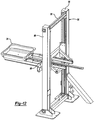
- the packaging system 24 further includes a transfer mechanism 60 , as shown in Figure 1 , that is disposed adjacent the rotary stretch wrapping device 30 , and more specifically it extends outwardly from between adjacent legs 34 of the frame 32 .
- the transfer mechanism 60 allows for the transportable container 20 to be transferred away from the packaging system 24 after the transportable container 20 has been wrapped by the rotary stretch wrapping device 30 .
- the transfer mechanism 60 is a conveyor, but it may be any transfer mechanism 60 known in the art.
- the transportable container 20 is transferred to the transfer mechanism 60 from the lift mechanism 56 so that the transportable container 20 may be moved away from the rotary stretch wrapping device 30 , thus allowing the packaging system 24 to continuously produce transportable containers 20.
- the packaging system 24 may further include a closure arm 62 , as shown in Figure 5 , that after filling of the transportable container 20 sweeps across the top of the transportable container 20 to knock the open top 122 of the bag 28 to a side of the transportable container 20 .
- the closure arm 62 may be secured to the support portion 46 of the rotary stretch wrapping device 30 and sweeps in a horizontal direction to position the open top 122 of the bag 28 in a folded over position for closing of the transportable container 20 .
- additional layer of stretch wrap 54 may be applied from the rotary stretch wrapping device 30 over the folded over bag 28 to seal and close the transportable container 20.
- the packaging system 24 may further include a platform section 64 , as shown in Figure 1 , that extends around a portion of the packaging system 24 .
- the platform section 64 may include a series of levels and walkway portions around the packaging system 24 .
- the platform section 64 may also include stairs or a ladder to gain access to the series of levels and walkway portions.
- the platform portion allows an operator to gain access to many of the components of the packaging system 24 for cleaning and maintenance of the components.
- the packaging system 24 may further include a secondary frame 66 for positioning a slip frame former 58 , gentle handling hopper 68 , and intermediate carrier 78 relative to the rotary stretch wrapping device 30 .
- the secondary frame 66 is disposed above the rotary stretch wrapping device 30 and intersects the frame 32 so that the slip frame former 58 , gentle handling hopper 68 , and intermediate carrier 78 can move horizontally and vertically relative to the rotary stretch wrapping device 30 .
- the packaging system 24 utilizes the slip frame former 58 to shape and form the transportable container 20 .
- the slip frame former 58 is secured to the secondary frame 66 by a plurality of former supports 144 that extend downwardly from the secondary frame 66 , and is moveable both vertically and horizontally along the former supports 144 and secondary frame 66 .
- the slip frame former 58 is positioned within the frame 32 of the rotary wrapping system and directly above the ring portion 48 .
- the slip frame former 58 extends downwardly from the secondary frame 66 and former supports 144 and is centered in the rotary stretch wrapping device 30 such that the ring portion 48 is positioned about the slip frame former 58 to move vertically upwards and downwards about the slip frame former 58 .
- the slip frame former 58 may be round, square or any other shape known in the art.
- the shape of the slip frame former 58 is chosen based on the desired shape of the transportable container 20 .
- the slip frame former 58 includes at least one former wall 126 having an outer surface that defines a frame opening 70 .
- the former walls 126 are from about 6 to 15 inches in height and may be made from metal, plastic, or any other material known in the art.
- the former walls 126 are configured such that the frame opening 70 is the desired shape in which the transportable container 20 will be formed into.
- the former walls 126 have a continuous outer surface that extends from the former bottom 136 of the slip frame former 58 to the former top 134 of the slip frame former 58 .
- the slip frame former 58 When the slip frame former 58 is used in addition to a bottom support 26 , the slip frame former 58 will be generally the same shape as the bottom support 26 so as to hold the desired shape of the bottom support 26 .
- the slip frame former 58 may be a solid shape having former walls 126 or consist of a former base having former arms or fingers extending downwardly from the former base.
- the stretch wrap 54 that is used to secure the transportable container 20 overlaps the outer surface of the slip frame former 58 so as to maintain the shape of the slip frame former 58 .
- the outer surface of the slip frame former 58 may be altered to allow for the slip frame former 58 to be easily pulled away from the stretch wrap 54 as the level of bulk goods 22 in the transportable container 20 increases and the bottom support 26 is moved away from the slip frame former 58 .
- the outer surface of the slip frame former 58 particularly the corners of the former walls 126 or the downwardly extending arms, may be altered by a Teflon coating, a dimpled surface, or any other method known in the art for decreasing the amount of friction between the slip frame former 58 and stretch wrap 54 .
- the former walls 126 include a former base having arms that extend downwardly from the former base. This embodiment decreases the outer surface of the slip frame former 58 and decreases the amount of friction between the slip frame former 58 and the stretch wrap 54 .
- the slip frame former 58 is octagonally shaped having four long wall portions 72 and four short wall portions 74 , with each of the adjacent long wall portions 72 being connected by a short wall portion 74 .
- Each of the four long wall portions 72 extend between ends and generally form a square, with each of the long wall portions 72 being spaced at adjacent ends.
- Each of the short wall portions 74 extend diagonally between adjacent ones of the ends of the long wall portions 72 to form a generally octagonally shaped slip frame former 58 .
- edges 128 where each of the long wall portions 72 engages a short wall portion 74 may be rounded to minimize the friction between the slip frame former 58 and stretch wrap 54 to allow the stretch wrap 54 to slide free from the slip frame former 58 during operation without tearing.
- each of the long wall portions 72 and short wall portions 74 may be concaved inward so that transportable container 20 formed has a straight side without any budge in the middle.
- the slip frame former 58 also act as a force control mechanism, i.e., the wrap is applied to the slip frame former 58 as opposed to being applied directly to the product. As such, the slip frame former 58 reduces product damage that could result from the direct application of the stretch wrap 54 to the bulk goods 22 in the transportable container 20.
- the exemplary embodiment includes a scrunched bag system 76 having an intermediate carrier 78 for holding a flexible bag 28 in an open and scrunched or bunched position.
- the bag 28 is held by the intermediate carrier 78 in a scrunched position by tension from the intermediate carrier 78 against the bag 28 and then released from the intermediate carrier 78 without mechanical interaction as the bag 28 is released and the transportable container 20 is formed.
- the flexible bag 28 includes an open top 122 and a closed base 124 to form the transportable container 20 of bulk goods 22 .
- the flexible bag 28 defines an open top 122 for receiving bulk goods 22 .
- the closed base 124 can be formed into the bag 28 or the bag 28 can be a continuous tubular roll wherein the closed base 124 is formed by folding over the tube, bunching the tube up, or by twisting and tying off a length of the tube which later could be used as a pour spout during subsequent unloading of the bulk goods 22 .
- the bag 28 is preferably a gusseted bag 28 and can be formed from any suitable material for the bulk goods 22 disposed in the bag 28 of the transportable container 20 , such as for example, low density polyethylene, high density polyethylene, a food grade polymer, or nylon.
- the intermediate carrier 78 includes a rigid carrier base 80 that is disposed about a base axis A B .
- a plurality of carrier arms 82 are pivotally connected to the carrier base 80 and extend between a first arm end 114 and a second arm end 116.
- Each of the carrier arms 82 extend outwardly, preferably angularly outwardly, from the carrier base 80 to hold the bag 28 in a scrunched position.
- Each of the carrier arms 82 are pivotally connected, via a pivotal connection 118 , to the carrier base 80 at the first arm end 114 to pivot each of the carrier arms 82 at the first arm end 114 to allow the second arm end 116 to move radially inward and outward.
- the pivotal connection 118 may be any type of pivotal connection 118 known in the art.
- the pivotal connection 118 includes a bracket portion 146 secured to the carrier base 80 , with the first arm end 114 being pivotally connected to the bracket portion 146 by a bolt or some other pivoting mechanism 148 .
- An elastomeric joint 120 is disposed adjacent the pivotal connection 118 between each of the first arm ends 114 and the carrier base 80 to bias each of the second arm ends 116 radially outward. The biasing of the second arm ends 116 radially outward provides tension against the bag 28 from each of the second arm ends 116 to hold the bag 28 in the scrunched position.
- the carrier base 80 of the intermediate carrier 78 is a food contact surface and is designed to be easy to clean and includes acceptable food contact materials. While the carrier base 80 may be any shape known in the art, including but not limited to, round, square and rectangular, the shape in the exemplary embodiment is U-shaped. The U-shaped carrier has an open end 150 to ease the maneuverability of the intermediate carrier 78 into and out of the packaging system 24 . While the shape of the intermediate carrier 78 is open ended in the exemplary embodiment, it could be closed.
- the intermediate carrier 78 includes a plurality of carrier arms 82 . While at least three arms are required, any number of carrier arms 82 could be used. In the exemplary embodiment, the intermediate carrier 78 has four carrier arms 82 .
- the carrier arms 82 are pivotally connected to the carrier base 80 .
- the carrier arms 82 extend angularly from the carrier base 80 to the second arm end 116 , and are biased radially outwardly to provide tension against the bag 28 disposed thereon.
- the carrier arms 82 of the intermediate carrier 78 are pivoted and biased to the carrier base 80 via an elastomeric joint 120 , such as a silicon rubber joint, but may be pivoted and biased by any biasing mechanism known in the art.
- Each of the second arm ends 116 may include a cap portion or a rounded portion 152 to assist with guiding the bag 28 onto the intermediate carrier 78 .
- the second arm ends 116 create a plurality of contact points 138 between the intermediate carrier 78 and the bag 28 .
- the plurality of contact points 138 maintain contact with the bag 28 to create an opening in the bag 28 , and hold the bag 28 in its proper open position.
- the second arm ends 116 push outwardly against the inside surface of the flexible bag 28 creating tension on the bag 28 to secure the bag 28 onto the intermediate carrier 78 .
- the biasing of the carrier arms 82 outwardly on the bag 28 allows the bag 28 to be held and released by the intermediate carrier 78 without puncturing the bag 28 .
- the intermediate carrier 78 may include at least one support arm 86 that extend from the carrier base 80 .
- the intermediate carrier 78 includes a plurality of support arms 86 that extend radially from the carrier base 80 .
- the support arms 86 are used to engage the packaging system 24 and secure the intermediate carrier 78 to the packaging system 24 .
- the support arms 86 provide a means for handling the carrier base 80 .
- the support arm 86 could allow an operator or machine to pick up and move the intermediate carrier 78 between an operating or in-use position and non-operating or non-use position.
- the bag 28 used to create the transportable container 20 is fed onto the intermediate carrier 78 .
- the bag 28 may be fed manually by an operator, automatically with a feeder, or a combination of manual and automatic. In the exemplary embodiment the bag 28 is fed manually by a human operator.
- a feeder is used to fed the bag 28 onto the intermediate carrier 78 .
- the feeder may be independent of the packaging system 24 . Prior to placement on the packaging system 24 , the intermediate carrier 78 is placed onto the feeder. The open top 122 of the bag 28 is placed around the plurality of carrier arms 82 .
- the feeder controls the flow of the bag 28 onto the intermediate carrier 78 .
- the feeder may include plurality of rollers and/or belts to uniformly control the feed of the bag 28 onto the intermediate carrier 78 .
- Uniformly feeding the bag 28 onto the intermediate carrier 78 allows for bag 28 to be uniformly dispersed from the intermediate carrier 78 when forming the transportable container 20 . Uniform disbursement of the bag 28 from the intermediate carrier 78 is useful in maintaining a desired shape for the transportable container 20 .
- the intermediate carrier 78 is transported to the packaging system 24 . This can be done by a human operator, a robot or other mechanical means. In the exemplary embodiment, the intermediate carrier 78 is transported via a carrier lift system 88 , as shown in Figure 13 .
- the carrier lift system 88 of the present invention includes a lift leg 90 and a vertically movable lift arm 92 .
- the lift arm 92 is rotatable on the lift leg 90 so as to be able to provide the function of removing an empty intermediate carrier 78 from the packaging system 24 and placing a loaded intermediate carrier 78 in its place.
- the lift arm 92 interacts with one of the support arms 86 extending from the intermediate carrier 78 to pick up and transfer the intermediate carrier 78 .
- the intermediate carrier 78 is secured to the packaging system 24 such that the scrunched bag 28 disposed on the intermediate carrier 78 is placed through the frame opening 70 of the slip frame former 58 .
- the open top 122 is disposed adjacent a feed source 130
- the closed base 124 of the bag 28 is placed adjacent the bottom support 26 .
- the intermediate carrier 78 is secured to and moveable along the secondary frame 66 in both a vertical and horizontal direction. The secondary frame 66 maintains the position of the intermediate carrier 78 relative to the feed source 130 .
- the intermediate carrier 78 provides for a consistent release of the bag 28 as the bottom support 26 moves downwardly to accommodate additional bulk goods 22.
- the consistent release of the bag 28 is due to the equal pressure from the carrier arms 82 on the bag 28 .
- the transportable container 20 includes a bottom support 26 which forms the base of the transportable container 20 .
- the bottom support 26 includes, but is not limited to a transporter base, slip sheet, pallet or any other bottom support 26 known in the art.
- the slip sheet is typically a folded sheet of cardboard, but may be any other material known in the art, including but not limited to plastic.
- the pallet may be wood, plastic or any other material known in the art. Typically, the pallet and the slip sheet are used together.
- the bottom support 26 is a transporter base and begins the initial forming of the transportable container 20 .
- the transporter base is made of molded plastic, but may be manufactured by any process known in the art and made of any other material known in the art.
- the transporter base is square, but the transporter base may be round or any other shape known in the art.
- a square transporter base is utilized to produce a square transportable container 20 while a round transporter base is utilized to produce a round transportable container 20 .
- the square transporter base which results in a square transportable container 20 , is the preferred shape.
- the square transportable container 20 allows for the greatest amount of space to be utilized when a plurality of transportable containers 20 are placed next to one another in a shipping truck.
- the round transporter base which results in a round transportable container 20 , will lead to a void or wasted space being present when the round transportable containers 20 are placed next to one another in a shipping truck.
- the transporter base initially forms the bulk goods 22 disposed in the transportable container 20 and further allows for the transportation of the transportable container 20 .
- the transporter base includes a bottom and a wall extending peripherally from the bottom to a wall end. A plurality of ears extend radially outward from the wall end. The wall assists in the initial shaping of the transportable container 20 .
- the transporter base includes at least one pair of recesses that extend upwardly from the bottom of the transporter base so that the tines of a transporting device, such as a fork lift, can pick up and move the transportable container 20 of bulks goods.
- the transporter base may further include a plurality of inwardly extending notches so the bulk goods 22 will not conform directly to the inner surface of the transporter base, which may be problematic in removing the bulk goods 22 from the transporter base.
- the packaging system 24 includes a transporter base transfer system 94 .
- the transfer system 94 is disposed adjacent the rotary stretch wrapping device 30 of the packaging system 24 .
- the transfer system 94 includes a brace portion 96 for supporting the transfer system 94 , a lifting portion 98 and pick and place portion 100 .
- the lifting portion 98 is vertically movable along the brace portion 96 .
- the pick and place portion 100 includes a pick arm 102 for picking up the bottom support 26 and placing it on the lifting portion 98 .
- the lifting portion 98 includes pairs of horizontally extending rails that are secured to the brace portion 96 to move upwardly and downwardly along the brace portion 96 .
- a first end of the lifting portion 98 is disposed adjacent the pick and place portion 100 to receive a bottom support 26 from the pick and place portion 100 .
- a second end of the lifting portion 98 is disposed within the frame 32 of the rotary stretch wrapping device 30 to place the bottom support 26 in a centered position within the frame 32 of the packaging system 24 .
- the lift mechanism 56 is incorporated into the transfer system 94 . That is, the lifting portion 98 of the transfer system 94 acts as the lift mechanism 56 for lifting the bottom support 26 vertically upwardly and downwardly in operation.
- the packaging system 24 further includes at least one feed source 130 , generally indicated, to introduce the bulk goods 22 into the transportable container 20 .
- the feed source 130 may include a hopper 68 , conveyor, or any other source known in the art to feed bulk goods 22 into the transportable container 20 .
- the feed source 130 may be a gentle handling hopper 68 for filling the bag 28 and creating the transportable container 20 .
- the gentle handling hopper 68 is disposed above the rotary stretch wrapping device 30 during operation.
- the hopper 68 may be supported and moveable, both vertically and horizontally, along the secondary frame 66 .
- the hopper 68 minimizes the vertical drop of the bulk goods 22 into the bag 28 to minimize breakage of the bulk goods 22 .
- the hopper 68 is positioned over the open top 122 of the bag 28 for feeding bulk goods 22 into the transportable container 20 .
- the hopper 68 is disposed between the rotary stretch wrapping device 30 and a feed source 130 , such as, a conveyor to feed bulk goods 22 into the transportable container 20 .
- the hopper 68 is stationary during filling of the transportable container 20 .
- the hopper 68 remains stationary as the bottom support 26 moves downwardly in response to the amount of the bulk goods 22 in the transportable container 20 .
- the bottom support 26 is placed at a position adjacent to the slip frame former 58 near the upper portion of the rotary stretch wrapping device 30 .
- the closed base 124 of the bag 28 rests in the bottom support 26 that is placed on and movable with the lift mechanism 56 or the lifting portion 98 of the transfer system 94 .
- the hopper 68 includes a hoop portion 104 that extends from a bottom end of the hopper 68 to push down on the bag 28 and assist in placing the bag 28 in contact with the bottom support 26 .
- the hoop portion 104 is tubular and spaced from the bottom of the hopper 68 to create space between the bottom support 26 and the bottom of the hopper 68 .
- the bottom support 26 along with the closed base 124 of the bag 28 are moved in a downward direction to accommodate additional bulk goods 22 from the stationary hopper 68 .
- the weight of the bulk goods 22 will keep the closed base 124 of the bag 28 in the bottom support 26 as the bottom support 26 moves downwardly.
- the hopper 68 includes a hopper opening 106 to receive the bulk goods 22 from a secondary feed source 130 .
- the secondary feed source 130 is a conveyor and the bulk goods 22 are fed from the conveyor end into the hopper opening 106.
- the hopper 68 includes a distributing end that is positioned over the open top 122 of the bag 28 at a predetermined distance above the level of bulk goods 22 for distributing goods.
- the hopper 68 is operated by maintaining the bulk goods 22 at a relatively high level within the hopper 68 .
- the bulk goods 22 do not have to fall far from the conveyor end into the hopper opening 106 .
- the movement of the bulk goods 22 through the hopper 68 is controlled such that the bulk goods 22 fed from the distributing end of the hopper 68 into the transportable container 20 have a shorter distance to fall.
- the transportable container 20 breaks the fall of the bulk goods 22 from the conveyor end to the bag 28 into two short falls as opposed to one larger fall. The two shorter falls minimizes the breakage of the bulk goods 22 .
- the hopper 68 may include a modulating valve disposed at the distributing end to adjust the flow of the bulk goods 22 from the hopper 68 into the transportable container 20 .
- a cone, plate, or screw may also be used to adjust the flow of the bulk goods 22 from the hopper 68 .
- the modulating valve moves closer to and further away from a valve seat to keep the level of the bulk goods 22 at a desired level within the hopper 68 .
- the modulating valve may further be rotatable based the bulk goods 22 being distributed from the distribution end of the hopper 68 .
- the top hat valve will move away from the valve seat to distribute the bulk goods 22 to the transportable container 20 at an increased rate thus lowering the level of the bulk goods 22 in the hopper 68 such that the bulk goods 22 will not spill out of the hopper opening 106. If the level of bulk goods 22 within the hopper 68 is below the desired level the top hat valve will move towards the valve seat to distribute the bulk goods 22 into the transportable container 20 at a decreased rate thus the raising the level of the bulk goods 22 in the hopper 68 to minimize the distance the bulk goods 22 must fall from the feed source 130.
- the bulk goods 22 fall a shorter distance from the feed source 130 into the hopper 68 and gently and gradually travel to the distributing end of the hopper 68 to be distributed into the transportable container 20 to form the transportable container 20 .
- the valve helps distribute the bulk goods 22 within the transportable container 20 to maintain an even fill and to have a flat top, thus increasing the amount of bulk goods 22 in the transportable container 20 .
- the modulating valve may further include a bulk goods distributor 112 .
- the bulk goods distributor 112 is at least one chute, fin or wing that aids in the distribution or preferential flow of the bulk goods 22 from the distributing end of the hopper 68 , but the bulk goods distributor 112 may be any mechanism known in the art of preferential flow of bulk goods 22 .
- the bulk goods distributor 112 may be flat, can include side walls, be rounded, or any other configuration based on the desired flow and the type of bulk goods 22 being distributed.
- the bulk goods distributor 112 may be incorporated into the design of the modulating valve or it may be a separate and distinct unit that can be attached to the modulating valve.
- the bulk goods distributor 112 allows for distribution of bulks goods to desired locations, particularly the corners of the transportable container 20 , which aids in the forming of square or rectangular shaped transportable containers 20 .
- the bulk goods distributor 112 allows for more flow of bulk goods 22 to the corners of the square or rectangular transportable container 20 to improve stability and shape consistency of the square or rectangular loads.
- the bulk goods distributor 112 allows for the flow of bulk goods 22 from the distributing end of the hopper 68 to be controlled and directed to desired portions of the transportable container 20 to aid in the shaping and optimal filling of the transportable container 20 .
- the hopper 68 may include a sensor to measure the hopper fill level of bulk goods 22 in the hopper 68 .
- the sensor is in communication with the modulating valve to control the rate of distribution of the bulk goods 22 and the hopper fill level in the hopper 68 .
- the sensor monitors the amount of bulk goods 22 in the hopper 68 and regulates the modulating valve, cone, plate, or screw to maintain the bulk goods 22 height or hopper fill level in the hopper 68 .
- a transportable container 20 of bulk goods 22 is formed from the packaging system 24 .
- the bottom support 26 is placed onto the lift mechanism 56 or the lift arm 92 of the transfer device, as shown in Figure 2 . This is done using the transfer system 94 where a pick arm 102 is used to place the bottom support 26 on to the lifting portion 98 of the transfer system 94 .
- the bottom support 26 is moved, as shown in Figure 3 , horizontally along the lifting portion 98 to a position vertically below the slip frame former 58 .
- the transportable container 20 may be formed with or without a bag 28 .
- a bag 28 When a bag 28 is included, the bag 28 having an open top 122 and closed base 124 that has been bunched and placed onto the intermediate carrier 78 is transferred from the feed station to the secondary frame 66 using the carrier lift system 88.
- the intermediate carrier 78 is secured to the secondary frame 66 with the open top 122 being adjacent the feed source 130 .
- the secondary frame 66 moves the hopper 68 and intermediate carrier 78 to a position that is above the rotary stretch wrapping device 30 , with the open top 122 of the bag 28 being disposed adjacent the feed source 130 and the closed base 124 of the bag 28 being positioned vertically below the open top 122 .
- the bottom of the intermediate carrier 78 is placed through the frame opening 70 of the slip frame former 58 and adjacent the bottom support 26 .
- the feed source 130 is placed over the bag 28 to create a vertical space between the distributing end and closed base 124 .
- the hoop portion 104 of the hopper 68 that extends from the end of the hopper 68 pushes downward on the bag 28 to place the bag 28 in contact with the bottom support 26 .
- the intermediate carrier 78 is secured to the secondary frame 66 relative to the feed source 130 , and the closed base 124 of the bag 28 is disposed in the bottom support 26 , which is placed onto the lift mechanism 56 .
- the bulk goods 22 are dispensed from the feed source 130 , in the exemplary embodiment, the distributing end of the hopper 68 through the open top 122 of the bag 28 into the closed base 124 of the bag 28 to establish a level of bulk goods 22 in the bag 28 .
- the feed source 130 remains stationary during the dispensing step to maintain the vertical space between the feed source 130 and the level of bulk goods 22 in the bag 28 or transportable container 20 .
- the stretch wrap 54 from the stretch wrapping device 30 is disposed radially about the non-rotating bottom support 26 and a portion of the at least one former wall 126 of the non-rotating slip frame former 58 to initially form the transportable container 20 . This can be done prior to, simultaneously with, or following the introduction of bulk goods 22 from the feed source 130 into the transportable container 20 .
- the closed base 124 of the bag 28 moves relative to the intermediate carrier 78 to distribute the bag 28 from the intermediate carrier 78 as the amount of bulk goods 22 in the bag 28 increases.
- the closed base 124 of the bag 28 moves downwardly with the bottom support 26 from the stationary intermediate carrier 78 as the amount of the bulk goods 22 in the transportable container 20 increases.
- the bottom support 26 is moved vertically downwardly relative to the stationary slip frame former 58 in response to the amount of the bulk goods 22 in the transportable container 20 .
- the stretch wrap 54 from the rotary stretch wrapping device 30 is wrapped around the bottom support 26 and the slip frame former 58 to initially form the transportable container 20 .
- the bottom support 26 is moved in a downward direction to accommodate additional bulk goods 22 in the transportable container 20 .
- the rotary stretch wrapping device 30 maintains its vertical position during filling of the transportable container 20 and continuously applies layers of stretch wrap 54 to the slip frame former 58 .
- the bottom support 26 moves downwardly relative to the slip frame former 58 to disengage the previously disposed portions of the stretch wrap 54 from the slip frame former 58 as the amount of bulk goods 22 increases in the transportable container 20 and additional layers of stretch wrap 54 are applied.
- the movement of the bottom support 26 downward is controlled based on the amount of bulk goods 22 in the transportable container 20 .
- the movement can be controlled in response to the weight of the bulk goods 22 in the transportable container 20 as determined by a scale, in response level of bulk goods 22 in the transportable container 20 as determined by a sensor, or a combination of weight and fill level.
- the movement of the bottom support 26 downward is based on the weight of the bulk goods 22 in the transportable container 20 in the initial stages of filling. Once the level of bulk goods 22 has reached a level where a sensor can detect the level of bulk goods 22 in the container, the movement of the bottom support 26 in the downward direction is controlled via a sensor that measures the level of bulk goods 22 in the transportable container 20.
- the slip frame former 58 retains its position relative to the level of bulk goods 22 in the transportable container 20 as the amount of bulk goods 22 increases during filling of the bag 28 to form the transportable container 20 .
- the slip frame former 58 is secured adjacent the upper support 36 of the rotary stretch wrapping device 30 and remains stationary as the bottom support 26 move vertically downward. As the bag 28 fills, the bottom support 26 is moved in a downward direction to accommodate additional bulk goods 22 and as such, the level of bulk goods 22 remains constant relative to the slip frame 32 .
- This level of bulk goods 22 may top out within the slip frame former 58 or it may top out above the top of the slip frame former 58 , as shown in Figure 4 .
- Consistent low building force on the product created by slip frame former 58 and bulk goods 22 own weight allows the bulk goods 22 to settle into the shape of the slip frame former 58 and compact tightly.
- the level of bulk goods 22 tops out above the former top 134 of the slip frame former 58 to create a head to allow for settling and a more compact unit, less voids, and more bulk goods 22 within the transportable container 20 . Less breakage occurs due to less voids.
- the film dispenser 50 which is mounted on the ring portion 48 and supported by the support portion 46 of the vertically moveable wrapping portion 44 , rotates about a vertical axis A v as the vertically moveable wrapping portion 44 spirally wraps the stretch wrap 54 about the transportable container 20 .
- the film dispenser 50 maintains its vertical position along the frame 32 of the rotary stretch wrapping device 30 .
- the stretch wrap 54 that is used to secure the transportable container 20 overlaps the outer surface of the slip frame former 58 so as to maintain the shape of the slip frame former 5 8 .
- the previously disposed layer of stretch wrap 54 disengage the slip frame former 58 as new layers of stretch wrap 54 are applied to the slip frame former 58 .
- the outer surface of the slip frame former 58 may be altered to allow for the slip frame former 58 to be easily pulled away from the stretch wrap 54 as the level of bulk goods 22 in the transportable container 20 increases and the bottom support 26 is moved away from the slip frame former 58 .
- Additional layers of stretch wrap 54 may be applied to the transportable container 20 to provide additional support.
- the addition layers of stretch wrap 54 could be applied in a crisscross pattern. That is, the stretch wrap 54 is applied to the transportable container 20 at a bottom corner adjacent the bottom support 26 and extend to a top corner adjacent the top of the transportable container 20 on an opposite side of the transportable container 20 . This can be repeated a plurality of times staring from different bottom corners to create the crisscross pattern of stretch wrap 54 on the transportable container 20 .
- the former walls 126 of the slip frame former 58 may move radially inward and outward as the bottom support 26 moves downwardly from the slip frame former 58 to form the transportable container 20 .
- the radial position of the slip frame former 58 may be adjusted radially to modify the shape of the transportable container 20.
- the radial movement of the former walls 126 of the slip frame former 58 may be controlled by hydraulic pistons, pneumatic pistons, a geared mechanism or any other method known in the art.
- slip frame former 58 is segmented or made of fingers or rods.
- Each segment is movable independently or on a linkage such that when a command is received to move the slip frame former 58 radially inward or outward, the segments move in two directions, thus enabling the sides to move closer together or farther apart.
- This motion is controlled based on the particular shape desired.
- the radial movement of the slip frame former 58 results in the transportable container 20 having a shape that varies radially in vertical relationship to the bottom support 26 .
- the shape of the transportable container 20 could be hour glass shaped, tapered, pumpkin shaped or any other desired shape known in the art.
- the radial movement of the slip frame former 58 provides the benefit of increasing the effective hoop force on the bulk goods 22 that are more difficult to lock up, resulting in a transportable container 20 having a corrugated shape in vertical relationship to the bottom support 26 .
- the transportable container 20 can be closed or left open depending on bulk goods 22 .
- certain bulk goods 22 such as wood chips, sand, gravel, and other bulk goods 22 , may not require that transportable container 20 be closed.
- the stretch wrap 54 would be applied around the bulk goods 22 to secure the bulk goods 22 and create the transportable container 20 .
- the transportable container 20 may be closed in any of a variety of manners known in the art including, but not limited to: sonic or heat welding of the top of the transportable container 20 , closure of the top of the transportable container 20 with a plastic pull tie, closure of the top of the transportable container 20 with wire or rope, closure of the top of the transportable container 20 with a clamp, and other closure means known in the art.
- the packaging system 24 includes a closure arm 62 that after filling of the transportable container 20 sweeps across the top of the transportable container 20 to knock the open top 122 of the bag 28 to a side of the transportable container 20.
- a closure arm 62 that after filling of the transportable container 20 sweeps across the top of the transportable container 20 to knock the open top 122 of the bag 28 to a side of the transportable container 20.
- additional layer of stretch wrap 54 are applied from the rotary stretch wrapping device 30 over the folded over bag 28 .
- the closure arm 62 is secured to the support portion 46 of the rotary stretch wrapping device 30 and sweeps in a horizontal direction to position the open top 122 of the bag 28 in the folded over position for closing of the transportable container 20 .
- the packaging system 24 preferably includes a control panel to permit an operator to control various functions, including, but not limited to, stop, start, filling dispenser speed, hopper 68 fill speed and interaction among the various components of the packaging system 24 .
- Such controls are known in the art.
- the packaging system 24 further includes conventional controls to maintain proper fill level, stretch wrap force, pre-stretching of the stretch wrap 54 , and sequencing. The relationship of these parameters is constantly monitored and automatically adjusted by means known in the art.
- the hopper 68 and feed source 130 may be in communication with the fill sensor of the packaging system 24 that monitors the level of bulk goods 22 in the bag 28 of the transportable container 20 via the control panel.
- the fill sensor may communicate with the hopper 68 to control, by shutting off or turning on, the flow of bulk goods 22 from the distributing end of the hopper 68 . Further, the fill sensor may communicate with the feed source 130 to control, by shutting off or turning on, the flow of bulk goods 22 from the feed source 130 into the hopper 68.
- the present invention provides for a method of producing a transportable container 20 for supporting bulk goods 22 .
- the method begins by positioning a non-rotating slip frame former 58 adjacent a non-rotating bottom support 26 .
- the slip frame former 58 surrounds a portion of the transportable container 20 and defines a frame opening 70 for receiving the bulk goods 22 from a feed source 130 .
- a stretch wrap 54 disposed from a rotary stretch wrapping device 30 , is prestretched from a non-stretched state to a stretched state prior to being disposed from the rotary stretch wrapping device 30 to the transportable container 20 .
- the rotary stretch wrapping device 30 is rotated radially about the non-rotating slip frame former 58 and non-rotating bottom support 26 to dispose the stretch wrap 54 in the stretched state radially about the bottom support 26 and a portion of the slip frame former 58 .
- the transportable container 20 is filled with bulk goods 22 from the feed source 130 through the frame opening 70 .
- At least one of the slip frame former 58 and the bottom support 26 are vertically moved relative to other in response to the fill level of the bulk goods 22 in the transportable container 20 .
- the slip frame former 58 and the bottom support 26 are vertically moved relative to other to expose the filled portion 132 of the transportable container 20 therebetween, as the transportable container 20 is filled with bulk goods 22 .
- the bottom support 26 of the transportable container 20 lowers as the transportable container 20 is filled and formed.
- the vertical movement of the bottom support 26 downward is controlled based on the amount of bulk goods 22 in the transportable container 20 .
- the slip frame former 58 is maintained in a position to surround the bulk goods 22 in the transportable container 20 .
- Previously disposed portions of the stretch wrap 54 are disengaged from the slip frame former 58 to allow the stretch wrap 54 to return to the non-stretched state and squeeze the filled portion 132 of the transportable container 20 and lock together the bulk goods 22 disposed therein as at least one of the slip frame former 58 and the bottom support 26 moves relative to other.
- the present invention further provides for a method of optimally packaging a transportable container 20 of bulk goods 22 .
- the method begins by placing a bag 28 with an open top 122 and a closed base 124 through a frame opening 70 defined by a slip frame former 58 .
- the slip frame former 58 includes at least one wall that extends between a former top 134 and a former bottom 136.
- the slip frame former 58 surrounds a portion of the bag 28 with the closed base 124 of the bag 28 being disposed adjacent a bottom support 26 and the open top 122 of the bag 28 being vertically spaced from the closed base 124 and disposed adjacent a feed source 130.
- a stretch wrap 54 is disposed from a stretch wrapping device 30 radially about the bottom support 26 and a portion of the slip frame former 58 to initially form the transportable container 20 .
- a fill level of bulk goods 22 is established in the bag 28 vertically above the former top 134 of the slip frame former 58 .
- At least one of the slip frame former 58 and the bottom support 26 are vertically moved relative to other in response to the fill level of the bulk goods 22 in the bag 28 to expose the filled portion 132 of the bag 28 therebetween as the bag 28 is filled with bulk goods 22.
- the bottom support 26 of the transportable container 20 lowers as the transportable container 20 is filled and formed. The vertical movement of the bottom support 26 downward is controlled based on the amount of bulk goods 22 in the transportable container 20 .
- the former top 134 of the slip frame former 58 is maintained in a position below the fill level of the bulk goods 22 in the bag 28 . Additional portions of stretch wrap 54 are disposed around a portion of the at least one wall of the slip frame former 58 to maintain the transportable container 20 for receiving bulk goods 22 as previously disposed portions of stretch wrap 54 disengage the slip frame former 58 during the vertically moving step.
- the fill level of bulk goods 22 is maintained vertically above the former top 134 of the slip frame former 58 during the vertically moving step to create a head of bulk goods 22 during the forming of the transportable container 20 .
- the head of bulk goods 22 allows for settling of the bulk goods 22 in the transportable container 20 and aids in the shaping and optimal filling of the transportable container 20 .
- the fill level of bulk goods 22 further allows for a more compact transportable container 20 with less voids between the bulk goods 22 and more bulk goods 22 disposed within the transportable container 20 .
Landscapes
- Engineering & Computer Science (AREA)
- Mechanical Engineering (AREA)
- Basic Packing Technique (AREA)
- Supplying Of Containers To The Packaging Station (AREA)
- Auxiliary Devices For And Details Of Packaging Control (AREA)
- Containers And Plastic Fillers For Packaging (AREA)
Claims (23)
- Procédé de production d'un contenant transportable (20) prévu pour recevoir des marchandises en vrac (22), et comprenant les étapes qui consistent à :mettre en place une machine à former à cadre de glissement (58) adjacente à un support de fond (26), la machine à former à cadre de glissement (58) possédant au moins une paroi de machine à former (126) (20) et définissant une ouverture de cadre (70) destinée à recevoir les marchandises en vrac (22) provenant d'une source d'alimentation (130) ;remplir le contenant transportable (20) avec des marchandises en vrac (22) provenant de la source d'alimentation (130) à travers l'ouverture de cadre (70) afin d'établir un niveau de remplissage ;déplacer verticalement au moins l'un parmi la machine à former à cadre de glissement (58) et le support de fond (26) par rapport à l'autre parmi la machine à former à cadre de glissement (58) et le support de fond (26), la machine à former à cadre de glissement (58) étant maintenue dans une position pour encercler les marchandises en vrac (22) dans le contenant transportable (22) ;désengager les parties de film étirable (54) disposées antérieurement de la machine à former à cadre de glissement (58) afin de comprimer la section remplie du contenant transportable (20) et enfermer ensemble les marchandises en vrac (22) disposées à l'intérieur pendant le déplacement d'au moins l'un parmi la machine à former à cadre de glissement (58) et le support de fond (26) par rapport à l'autre parmi la machine à former à cadre de glissement et le support de fond ; oùla machine à former à cadre de glissement (58) et le support de fond (26) sont tous deux non rotatifs,la machine à former à cadre de glissement (58) est de forme octogonale et comprend quatre sections de paroi longue (72) et quatre sections de paroi courte (74) qui s'étendent en diagonale entre les sections adjacentes desdites sections de paroi longue (72) pour former la machine à former à cadre de glissement de forme octogonale (58),les quatre sections de paroi longue (72) et les quatre sections de paroi courte (74) entourent une partie du contenant transportable (20), et chacune desdites sections de paroi courte (74) et desdites sections de paroi longue (72) est concave vers l'intérieur, et oùentre l'étape de mise en place de la machine à former à cadre de glissement (58) et du support de fond (26) non rotatifs et l'étape de remplissage du contenant transportable, ont lieu les étapes suivantes :• pré-étirage du film étirable (54) disposé par une banderoleuse rotative (30) qui passe d'un état non étiré à un état étiré ; où le pré-étirage est effectué par réglage de l'étendue à laquelle le film étirable (54) sera pré-étiré et appliqué au contenant transportable (20), à travers un contrôle de la tension de pré-étirage afin de s'ajuster au type de marchandises en vrac ;• rotation de la banderoleuse rotative (30) de façon radiale autour de la machine à former à cadre de glissement (58) et du support de fond (26) non rotatifs pour l'application du film étirable (54) à l'état étiré de façon radiale autour du support de fond (26) et d'une partie de la machine à former à cadre de glissement 58 pour la mise en forme initiale du contenant transportable (20) ;- le mouvement vertical d'au moins l'un parmi la machine à former à cadre de glissement (58) et le support de fond (26) par rapport à l'autre parmi la machine à former à cadre de glissement (58) et le support de fond (26), s'effectue en réponse au niveau de remplissage des marchandises en vrac (22) dans le contenant transportable (20) pour exposer la partie remplie du contenant transportable (20) entre les deux pendant le remplissage du contenant transportable (20) avec les marchandises en vrac (22) ;- une fois les parties du film étirable (54) disposées antérieurement désengagées de la machine à former à cadre de glissement, le film étirable (54) peut revenir à l'état non étiré.
- Procédé tel que décrit dans la revendication 1 comprenant en outre l'étape qui consiste à placer un sac (28) avec une partie supérieure ouverte (122) et une base fermée (124) à travers l'ouverture de cadre (70) définie par le cadre de glissement (58), où la machine à former à cadre de glissement (58) qui entoure une partie du sac (28) avec la base fermée (124) est disposée adjacente au support de fond (26), et la partie supérieure ouverte (122) est séparée verticalement de la base fermée (124) et disposée adjacente à la source d'alimentation (130) pour recevoir les marchandises en vrac (22).
- Procédé tel que décrit dans la revendication 1 comprenant en outre l'étape qui consiste à conserver la forme de l'ouverture du cadre (70) pendant le déplacement de l'un parmi la machine à former à cadre de glissement (58) et le support de fond (16) par rapport à l'autre parmi la machine à former à cadre de glissement (58) et le support de fond (26).
- Procédé tel que décrit dans la revendication 1 comprenant en outre l'étape consistant à appliquer des parties supplémentaires de film étirable (54) à l'état étiré, de façon radiale autour d'une partie de la machine à former à cadre de glissement (58) pour maintenir le contenant transportable (20) pour la réception des marchandises en vrac (22) pendant que les parties de film étirable (54) disposées antérieurement sont désengagées des sections de paroi longue (72) et des sections de paroi courte (74) de la machine à former à cadre de glissement (58).
- Procédé tel que décrit dans la revendication 1 comprenant en outre l'étape de contrôle du flux des marchandises en vrac (22) provenant de la source d'alimentation (130) jusqu'à l'intérieur du contenant transportable (20) avec un distributeur de marchandises en vrac (112), pour permettre la distribution des marchandises en vrac (22) à des positions spécifiques dans le contenant transportable (20) et faciliter la mise en forme et le remplissage optimal du contenant transportable (20).
- Procédé tel que décrit dans la revendication 5 où le contrôle du flux de marchandises en vrac (22) est défini aussi comme le contrôle du flux des marchandises en vrac (22) provenant de la source d'alimentation (130) jusqu'à l'intérieur du contenant transportable (20) avec un distributeur de marchandises en vrac (112) pour permettre la distribution des marchandises en vrac (22) jusqu'aux angles du contenant transportable (20) et faciliter la mise en forme et le remplissage optimal du contenant transportable (20).
- Procédé tel que décrit dans la revendication 1 comprenant en outre l'étape de contrôle du degré de pré-étirage en base au type de marchandises en vrac (22) afin de faciliter la mise en forme et le remplissage optimal du contenant transportable (20).
- Procédé d'emballage optimal d'un contenant transportable (20) de marchandises en vrac (22) comprenant les étapes qui consistent à:mettre en place un sac (28) avec une partie supérieure ouverte (122) et une base fermée (124) à travers une ouverture de cadre (70) définie par une machine à former à cadre de glissement de forme octogonale (58) avec quatre sections de paroi longue (72) et quatre sections de paroi courte (74) qui s'étendent entre une partie supérieure du cadre (134) et un partie inférieure du cadre (136), la machine à former à cadre de glissement (58) entourant une partie du sac (28) avec la base fermée (124) étant disposée adjacente au support de fond (26) et la partie supérieure ouverte (122) étant séparée verticalement de la base fermée (124) et disposée adjacente à une source d'alimentation (130), chacune desdites sections de paroi courte (74) et chacune desdites sections de paroi longue (72) étant de forme concave vers l'intérieur ;pré-étirer un film étirable (54) à partir d'une banderoleuse (30) avant l'étape d'application du film étirable, où le pré-étirage est effectué par réglage de l'étendue du film étirable (54) qui doit être pré-étiré et appliqué au contenant transportable (20), à travers le contrôle de la tension de pré-étirage afin de l'ajuster au type de marchandises en vrac ;appliquer de façon radiale le film étirable (54) à partir de la banderoleuse (30) autour du support de fond (26) et d'une partie de la machine à former à cadre de glissement (58) pour la mise en forme initiale du contenant transportable (20) ;établir un niveau de remplissage des marchandises en vrac (22) dans le sac (28) disposé verticalement au-dessus de la partie supérieure de la machine à former (134) de la machine à former à cadre de glissement (58) ;déplacer verticalement au moins l'un parmi la machine à former à cadre de glissement (58) et le support de fond (26) par rapport à l'autre parmi la machine à former à cadre de glissement (58) et le support de fond (26) en réponse au niveau de remplissage des marchandises en vrac (22) dans le sac (28) afin d'exposer la partie remplie du sac (28) entre les deux pendant le remplissage du sac (28) avec les marchandises en vrac (22), la partie supérieure de la machine à former (134) de la machine à former à cadre de glissement (58) étant maintenue dans une position au-dessous du niveau de remplissage des marchandises en vrac (22) dans le sac (28) ; etappliquer les parties supplémentaires de film étirable (54) autour d'une partie de la machine à former à cadre de glissement (58) pour maintenir le contenant transportable (20) pour la réception des marchandises en vrac (28) pendant que les parties de film étirable (54) disposées antérieurement sont désengagées des sections de paroi longue (72) et des sections de paroi courte (74) de la machine à former à cadre de glissement (58) pendant l'étape de déplacement vertical ;où le niveau de remplissage des marchandises en vrac (22) est maintenu verticalement au-dessus de la partie supérieure de la machine à former (134) de la machine à former à cadre de glissement (58) pendant l'étape de déplacement vertical pour créer une tête de marchandises en vrac (22) et placer les marchandises en vrac (22) dans le contenant transportable (20) afin de faciliter la mise en forme et le remplissage optimal du contenant transportable (20), et en outre pour obtenir un contenant transportable plus compact (20) avec moins d'espaces vides entre les marchandises en vrac (22) et plus de marchandises en vrac (22) à l'intérieur du contenant transportable (20).
- Procédé tel que décrit dans la revendication 8 comprenant en outre l'étape de contrôle du flux des marchandises en vrac (22) provenant de la source d'alimentation (130) jusqu'à l'intérieur du sac (28) avec un distributeur de marchandises en vrac (112) pour permettre la distribution des marchandises en vrac (22) jusqu'à des positions spécifiques dans le contenant transportable (20) et faciliter la mise en forme et le remplissage optimal du contenant transportable (20).
- Procédé tel que décrit dans la revendication 9 où le contrôle du flux des marchandises en vrac (22) est défini en outre comme le contrôle du flux des marchandises en vrac (22) provenant de la source d'alimentation (130) jusqu'à l'intérieur du sac (28) avec un distributeur de marchandises en vrac (112) pour permettre la distribution des marchandises en vrac (22) jusqu'aux angles du contenant transportable (20) et faciliter la mise en forme et le remplissage optimal du contenant transportable (20).
- Procédé tel que décrit dans la revendication 8 comprenant en outre l'étape de contrôle du degré de pré-étirage en base au type de marchandises en vrac (22) afin de faciliter la mise en forme et le remplissage optimal du contenant transportable (20).
- Procédé tel que décrit dans la revendication 8 où chaque support de fond (26) et chaque machine à former à cadre de glissement (58) sont non rotatifs, et la mise en place de l'étape du film étirable est définie en outre comme la mise en place d'un film étirable (54) à partir d'une banderoleuse rotative (30) qui se déplace de façon radiale autour du support de fond non rotatif (26) et de la machine à former à cadre de glissement non rotative (58) pour la mise en forme initiale du contenant transportable (20).
- Procédé tel que décrit dans la revendication 12 où la disposition des parties supplémentaires de l'étape de film étirable est définie en outre comme l'application de parties supplémentaires de film étirable (54) à partir d'une banderoleuse rotative (30) qui se déplace de façon radiale autour d'une partie de la au moins une paroi de machine à former (126) de la machine à former à cadre de glissement (58) pour maintenir le contenant transportable (20) pour la réception des marchandises en vrac (22) pendant que les parties de film étirable disposées antérieurement (54) sont désengagées des sections de paroi longue (72) et des sections de paroi courte (74) de la machine à former à cadre de glissement (58).
- Procédé tel que décrit dans la revendication 8 comprenant en outre l'étape qui consiste à désengager des parties de film étirable disposées antérieurement (54) de la machine à former à cadre de glissement (58) pour comprimer la partie remplie du sac (28) et enfermer ensemble les marchandises en vrac (22) disposées dans le sac (28) pendant le déplacement d'au moins l'un parmi la machine à former à cadre de glissement (58) et le support de fond (26) par rapport à l'autre parmi la machine à former à cadre de glissement (58) et le support de fond (26).
- Procédé tel que décrit dans la revendication 1 où le contenant transportable (20) comprend un sac (28), le procédé comprenant en outre l'étape qui consiste à fournir un dispositif de support intermédiaire (78) de soutien d'un sac écrasé (28) avec une extrémité ouverte (122) et une base fermée (124) et de mise en forme d'un contenant transportable (20) prévu pour supporter une pluralité de marchandises en vrac (28) et comprenant :une base de support rigide (80) disposée autour d'un axe de base AB ;une pluralité de bras de support (82) étant reliés de façon pivotante à ladite base de support (80) par une connexion pivotante (118) et s'étendant entre une première extrémité de bras (114) et une deuxième extrémité de bras (116), chacun desdits bras de support (82) s'étendant depuis ladite base de support (80) afin de maintenir le sac (28) dans une position écrasée, et où chacun desdits bras de support (82) sont reliés de façon pivotante par ladite connexion pivotante (118) à ladite base de support (80) dans ladite première extrémité de bras (114), pour faire pivoter chacun desdits bras de support (82) dans ladite première extrémité de bras (114) et permettre le déplacement radial de ladite deuxième extrémité de bras (116) vers l'intérieur et vers l'extérieur ; etun joint élastomère (120) disposé adjacent à ladite connexion pivotante (118) entre chacune desdites premières extrémités de bras (114) et ladite base de support (80) pour incliner chacune desdites deuxièmes extrémités de bras (116) de façon radiale vers l'extérieur afin d'appliquer une tension au sac (28) par chacune desdites deuxièmes extrémités de bras (116) et maintenir le sac (28) en position écrasée.
- Procédé tel que décrit dans la revendication 15 où chacun desdits bras de support (82) du dispositif de support intermédiaire (78) s'étend angulairement vers l'extérieur de ladite base de support (80) pour maintenir le sac (28) dans une position écrasée.
- Procédé tel que décrit dans la revendication 15 où ladite base de support (80) du dispositif de support intermédiaire (78) est en forme de U et inclut une extrémité ouverte (150) pour le mouvement du support intermédiaire (78) entre une position d'utilisation et une position de non-utilisation.
- Procédé tel que décrit dans la revendication 15 où ledit joint élastomère (120) du dispositif de support intermédiaire (78) est un joint en caoutchouc de silicone.
- Procédé tel que décrit dans la revendication 15 où chacune desdites deuxièmes extrémités de bras (116) du dispositif de support intermédiaire (78) est arrondie pour faciliter le positionnement du sac (28) sur le support intermédiaire (78) et créer une pluralité de points de contact (138) entre le support intermédiaire (78) et le sac (28).
- Procédé tel que décrit dans la revendication 15 où le dispositif de support intermédiaire (78) comprend aussi un sac (28) avec une extrémité ouverte (122) et une base fermée (124), ledit sac (28) étant disposé autour et en contact avec chacun des bras de support (82) afin d'être maintenu en position écrasée.
- Procédé tel que décrit dans la revendication 15 où le dispositif de support intermédiaire (78) comprend en outre, au moins un bras de support (86) qui s'étend depuis ladite base de support (80) pour s'engager avec un système d'emballage (24) et fixer le support intermédiaire (78) sur le système d'emballage (24).
- Procédé tel que décrit dans la revendication 1 où la machine à former à cadre de glissement (58) façonne et forme le contenant transportable (20) afin de contenir une pluralité de marchandises en vrac (22), et comprenant,
quatre sections de paroi longue (72) s'étendant chacune entre les extrémités et formant généralement un carré avec chacune desdites sections de paroi longue (72) étant séparées et adjacentes auxdites extrémités ; et
quatre sections de paroi courte (74) s'étendant chacune en diagonale entre les parties adjacentes desdites extrémités desdites sections de paroi longue (72) pour former la machine à former à cadre de glissement de forme octogonale (58),
où chacune desdites sections de paroi longue (72) est de forme concave vers l'intérieur afin de former une paroi généralement droite sur le contenant transportable (20). - Procédé selon la revendication 1 où la machine à former à cadre de glissement (58) comprend aussi une pluralité de bords (128), chacun desdits bords (128) étant formé à l'endroit où chacune desdites sections de paroi courte (74) s'engage avec chacune desdites sections de paroi longue (72), et où chacun desdits bords (128) est arrondi pour limiter le frottement entre ladite machine à former à cadre de glissement (58) et un film étirable (54) appliqué à ladite machine à former à cadre de glissement (58) pour permettre à ce film étirable (54) de glisser librement depuis la machine à former à cadre de glissement (58).
Priority Applications (2)
| Application Number | Priority Date | Filing Date | Title |
|---|---|---|---|
| EP17151670.1A EP3190055B1 (fr) | 2010-12-01 | 2011-12-01 | Dispositif de support intermédiaire |
| EP18186946.2A EP3421380B1 (fr) | 2010-12-01 | 2011-12-01 | Formeur de cadre coulissant |
Applications Claiming Priority (2)
| Application Number | Priority Date | Filing Date | Title |
|---|---|---|---|
| US41844810P | 2010-12-01 | 2010-12-01 | |
| PCT/US2011/062790 WO2012075228A2 (fr) | 2010-12-01 | 2011-12-01 | Contenant transportable pour les marchandises en vrac et procédé permettant de le constituer |
Related Child Applications (3)
| Application Number | Title | Priority Date | Filing Date |
|---|---|---|---|
| EP17151670.1A Division EP3190055B1 (fr) | 2010-12-01 | 2011-12-01 | Dispositif de support intermédiaire |
| EP17151670.1A Division-Into EP3190055B1 (fr) | 2010-12-01 | 2011-12-01 | Dispositif de support intermédiaire |
| EP18186946.2A Division EP3421380B1 (fr) | 2010-12-01 | 2011-12-01 | Formeur de cadre coulissant |
Publications (2)
| Publication Number | Publication Date |
|---|---|
| EP2646323A2 EP2646323A2 (fr) | 2013-10-09 |
| EP2646323B1 true EP2646323B1 (fr) | 2017-04-19 |
Family
ID=45218935
Family Applications (3)
| Application Number | Title | Priority Date | Filing Date |
|---|---|---|---|
| EP17151670.1A Active EP3190055B1 (fr) | 2010-12-01 | 2011-12-01 | Dispositif de support intermédiaire |
| EP18186946.2A Active EP3421380B1 (fr) | 2010-12-01 | 2011-12-01 | Formeur de cadre coulissant |
| EP11793977.7A Active EP2646323B1 (fr) | 2010-12-01 | 2011-12-01 | Contenant transportable pour les marchandises en vrac et procédé permettant de le constituer |
Family Applications Before (2)
| Application Number | Title | Priority Date | Filing Date |
|---|---|---|---|
| EP17151670.1A Active EP3190055B1 (fr) | 2010-12-01 | 2011-12-01 | Dispositif de support intermédiaire |
| EP18186946.2A Active EP3421380B1 (fr) | 2010-12-01 | 2011-12-01 | Formeur de cadre coulissant |
Country Status (9)
| Country | Link |
|---|---|
| US (2) | US9126705B2 (fr) |
| EP (3) | EP3190055B1 (fr) |
| JP (1) | JP6185387B2 (fr) |
| AU (1) | AU2011336548B2 (fr) |
| CA (3) | CA3025532C (fr) |
| ES (3) | ES2811053T3 (fr) |
| MX (1) | MX337810B (fr) |
| SG (1) | SG190181A1 (fr) |
| WO (1) | WO2012075228A2 (fr) |
Families Citing this family (12)
| Publication number | Priority date | Publication date | Assignee | Title |
|---|---|---|---|---|
| CA3025532C (fr) | 2010-12-01 | 2020-06-02 | Kellogg Company | Dispositif de transport intermediaire pour former un contenant transportable pour des produits en vrac |
| US20160109280A1 (en) * | 2014-10-15 | 2016-04-21 | The Boeing Company | Smart aircraft overhead luggage bin system |
| DE102014222367A1 (de) * | 2014-11-03 | 2016-05-04 | Robert Bosch Gmbh | Vorrichtung zu einem Bearbeiten eines Verpackungsbehälters |
| EP3070004B1 (fr) * | 2015-03-19 | 2017-08-23 | ITALDIBIPACK S.p.A. | Dispositif d'enroulement avec surface de levage |
| US10936879B2 (en) | 2016-12-19 | 2021-03-02 | The Boeing Company | System for displaying the status of use of aircraft overhead luggage storage bins |
| CN208963422U (zh) * | 2017-05-31 | 2019-06-11 | 耐克创新有限合伙公司 | 用于将互补鞋类物品装入鞋盒中的系统 |
| BR112020004016A2 (pt) * | 2017-08-31 | 2020-09-08 | Monsanto Technology Llc | sistema de entrega de sementes |
| US10723492B2 (en) * | 2017-09-21 | 2020-07-28 | Yamato Corporation | Depositor apparatus |
| CN111674583B (zh) * | 2020-06-18 | 2022-05-24 | 湖北高农科技有限公司 | 一种稻谷晾晒用快速装袋设备 |
| US11396433B1 (en) * | 2021-03-15 | 2022-07-26 | Flexicon Corporation | Bulk bag conditioner |
| CN115140360B (zh) * | 2022-08-29 | 2022-11-04 | 信承瑞技术有限公司 | 一种防水防火电缆包装生产设备 |
| CN117945050B (zh) * | 2024-03-27 | 2024-06-18 | 山西迎才物流设备科技有限公司 | 一种仓库码垛运输装置 |
Citations (1)
| Publication number | Priority date | Publication date | Assignee | Title |
|---|---|---|---|---|
| US20090301036A1 (en) * | 2008-06-05 | 2009-12-10 | Dave Ours | Unitary transporter base and shaper and slip frame former for forming a transportable container |
Family Cites Families (261)
| Publication number | Priority date | Publication date | Assignee | Title |
|---|---|---|---|---|
| US147944A (en) | 1874-02-24 | Improvement in elevators | ||
| US98848A (en) | 1870-01-18 | Improved dredging-machine | ||
| DE574994C (de) | 1933-04-22 | Pohl Franz | Rueckenschutz an Sackelevatoren fuer Steilfoerderung mit veraenderlicher Hubhoehe | |
| US887242A (en) | 1905-07-03 | 1908-05-12 | Wilhelm J Frank | Machine for lifting skins or hides from lime-pits or tan-pits. |
| US1061394A (en) | 1912-05-10 | 1913-05-13 | John H Michener Jr | Conveyer. |
| US1466724A (en) | 1920-12-28 | 1923-09-04 | Mcmeans William | Grain elevator |
| US1474625A (en) | 1923-01-24 | 1923-11-20 | Eckert Cecilie | Culinary press |
| US1861147A (en) | 1924-06-16 | 1932-05-31 | Steimel Peter | Automatic sacking balance with a conveying and a packing mechanism |
| US1590086A (en) | 1925-11-28 | 1926-06-22 | Luther F Day | Alfalfa meal and bran packer |
| US1649362A (en) | 1925-11-30 | 1927-11-15 | Nagel Carl | Method and apparatus for compressing loose material in bags |
| US1730295A (en) | 1927-04-07 | 1929-10-01 | Reuther Johann Wilhelm | Packing device for automatic sack-weighing machines |
| US1777224A (en) | 1929-01-29 | 1930-09-30 | Reuther Johann Wilhelm | Packing device for automatic sack-weighing machines |
| US1834472A (en) | 1929-04-20 | 1931-12-01 | George L Oliver | Sack jigger and shaper for grain thrashing machines |
| US1926986A (en) | 1932-03-22 | 1933-09-12 | Edward H Angier | Barrel liner |
| US1992046A (en) | 1933-03-02 | 1935-02-19 | Wesley P Shomaker | Adjustable support for endless conveyers |
| US2011978A (en) | 1933-10-20 | 1935-08-20 | Albert A Marks | Movable carriage for hay loaders |
| US2013215A (en) | 1934-01-05 | 1935-09-03 | Keystone Steel & Wire Co | Material transfer apparatus |
| DE621624C (de) | 1934-07-14 | 1935-11-11 | Max Noelle | Gliederfoerderband fuer Steilfoerderer mit veraenderlichem Fassungsraum der Becherkammern |
| US2074595A (en) | 1935-08-23 | 1937-03-23 | Shackelford Orie | Conveyer |
| US2419330A (en) | 1943-05-13 | 1947-04-22 | Gen Mills Inc | Compacting flour in bags |
| US2683522A (en) | 1946-10-03 | 1954-07-13 | Jeffrey Mfg Co | Multiple compartment bucket elevator |
| US2601480A (en) * | 1948-07-13 | 1952-06-24 | Delamere & Williams Company Lt | Bag opening and spreading mechanism |
| US2676739A (en) | 1950-06-03 | 1954-04-27 | Minnesota Scale Mfg Co | Bagging machine |
| US2702625A (en) | 1951-03-31 | 1955-02-22 | Hannah Jane Hapman | Bucket conveyer system |
| US2781799A (en) | 1951-05-14 | 1957-02-19 | Combined Metals Reduction Comp | Bag-filling apparatus |
| US2863475A (en) | 1954-05-14 | 1958-12-09 | Black Products Co | Bag settling device |
| US2765816A (en) | 1954-05-26 | 1956-10-09 | Clarence F Carter | Bag filling machine |
| US2973612A (en) * | 1956-02-20 | 1961-03-07 | William S Mcgowan | Bag opener |
| US2986860A (en) * | 1959-04-01 | 1961-06-06 | Gisholt Machine Co | Mandrel assembly for seal applying machine |
| US3066817A (en) | 1959-11-13 | 1962-12-04 | Cochran Equipment Company | Cargo transporting vehicle with extendible conveyor |
| US3287881A (en) * | 1962-10-10 | 1966-11-29 | Jelling Murray | Bag, bag supply and bag applying apparatus and method for use with continuous rolls of bags and the like |
| US3243937A (en) * | 1962-11-05 | 1966-04-05 | Waldorf Paper Prod Co | Apparatus for expanding bags |
| US3284986A (en) * | 1964-01-24 | 1966-11-15 | Duchin Daniel | Manually fed bagging machines |
| US3279523A (en) * | 1964-04-06 | 1966-10-18 | Pardue Edward | Spare fuel container for vehicles |
| US3260352A (en) | 1964-09-25 | 1966-07-12 | Leslie M Sheridan | Railway elevator for transporting material up an incline |
| US3269430A (en) * | 1965-05-13 | 1966-08-30 | Fmc Corp | Bag securing apparatus |
| US3374599A (en) | 1966-01-26 | 1968-03-26 | Du Pont | Method for packaging and apparatus therefor |
| US3533454A (en) | 1966-07-28 | 1970-10-13 | Douglas & Lomason Co | Packing method and apparatus for performing the method |
| US3509680A (en) * | 1967-12-18 | 1970-05-05 | Phillips Petroleum Co | Printing on packages |
| US3758410A (en) | 1968-03-05 | 1973-09-11 | Monsanto Co | Vicinal substituted alkanes |
| US3626654A (en) | 1968-04-17 | 1971-12-14 | Reynolds Metals Co | Method of overwrapping a package |
| US3570749A (en) | 1968-08-09 | 1971-03-16 | Showa Denko Kk | Heavy duty bags |
| US3578183A (en) | 1969-03-03 | 1971-05-11 | Perdue & Son Inc A W | Method and apparatus for conveying material |
| US3688893A (en) | 1970-02-26 | 1972-09-05 | Wallace Systems Inc W J | Materials handling machine |
| US3707127A (en) | 1970-03-05 | 1972-12-26 | Dow Chemical Co | Goods supporting pallet |
| US3593484A (en) | 1970-03-23 | 1971-07-20 | Joseph A Dussich | Method and apparatus for sequentially packaging materials into units of desired volume |
| FR2123091B1 (fr) | 1970-12-11 | 1974-03-22 | Est Aciers Fins | |
| US3847290A (en) | 1972-01-12 | 1974-11-12 | Borg Warner Canada Ltd | Bulk ship unloader |
| US3778962A (en) | 1972-03-30 | 1973-12-18 | Calcato Inc | Vacuum controlled vessel loading with particulate materials |
| DE2219490C3 (de) | 1972-04-18 | 1975-10-23 | F. Zimmermann & Co, 1000 Berlin | Vorrichtung zum Verpacken von senkrecht gestapelten Münzen, Wertzeichen od.dgl. Stapelteilen In einem aus einer Schrumpffolie bestehenden Beutel |
| US3785410A (en) | 1972-06-28 | 1974-01-15 | Carter Eng Co | Method and apparatus for vacuum filling open mouth bags |
| US3776435A (en) | 1972-07-14 | 1973-12-04 | Cincinnati Milacron Inc | Pallet |
| US3879917A (en) | 1973-01-10 | 1975-04-29 | Fmc Corp | Method and apparatus for packaging particulate material |
| US3848728A (en) | 1973-02-01 | 1974-11-19 | Butz Eng Corp | Conveyor and sorting system |
| FR2219873B1 (fr) | 1973-03-02 | 1976-05-21 | Boracier Sa | |
| US4007694A (en) | 1974-02-15 | 1977-02-15 | Monsanto Company | Unitary plastic pallet for handling heavy powder loads |
| US4113146A (en) | 1974-04-11 | 1978-09-12 | Better Agricultural Goals Corporation | Disposable container for bulk materials |
| US3961459A (en) | 1974-04-16 | 1976-06-08 | Bemis Company, Inc. | Method of and apparatus for wrapping a load in a wrapper of stretchable material |
| US3903677A (en) * | 1974-06-28 | 1975-09-09 | Us Agriculture | Opening and gripping mechanism for automatic produce-bagging machine that uses factory-roll polyethylene net tubing |
| US3906591A (en) | 1974-07-30 | 1975-09-23 | Boiardi Products Corp | Bridging clip for metal or plastic banding |
| US3902303A (en) | 1974-08-19 | 1975-09-02 | Henry E King | Stretch bag wrapping machine |
| US3944070A (en) | 1974-09-09 | 1976-03-16 | Phillips Petroleum Company | Pallet and an integral package utilizing the pallet |
| US3968626A (en) | 1974-11-11 | 1976-07-13 | Hobbs Oliver K | Apparatus for bagging material |
| US3951462A (en) | 1974-12-05 | 1976-04-20 | De Francisi Machine Corporation | Apparatus for feeding a powdered substance |
| US3949536A (en) | 1974-12-26 | 1976-04-13 | Etablissements M. Chapuis | Guiding device for an automatic bag-filling machine |
| US3943988A (en) | 1975-02-21 | 1976-03-16 | Sebastian John Consorti | Laundry bag |
| FR2316379A1 (fr) | 1975-07-02 | 1977-01-28 | Secmafer Sa | Degarnisseuse pour voies ferrees |
| DE2601858C3 (de) | 1976-01-20 | 1978-08-10 | Ludwig Boschert Maschinen- Und Apparatebau Gmbh & Co Kg, 7850 Loerrach | Stanzmaschine |
| US4050219A (en) | 1976-02-19 | 1977-09-27 | Comptex, Inc. | Bagging machine |
| US4078358A (en) | 1976-08-31 | 1978-03-14 | National Distillers And Chemical Corporation | Bag-hanging and bag-filling machines adapted for synchronous and independent operation and method of using same |
| FR2364831A1 (fr) | 1976-09-15 | 1978-04-14 | Fives Cail Babcock | Appareil de manutention, notamment elevateur a godets pour le dechargement de navires |
| US4074507A (en) | 1976-12-27 | 1978-02-21 | St. Regis Paper Company | Bag filling machine for powdery material |
| US4149755A (en) | 1977-05-31 | 1979-04-17 | Handleman Avrom Ringle | Fluidizable material handling apparatus |
| US4205930A (en) | 1977-05-31 | 1980-06-03 | Alack Charles S | Fluidizable material handling apparatus |
| US4106261A (en) | 1977-08-08 | 1978-08-15 | The Dow Chemical Company | Method of forming, filling, and sealing scrim reinforced plastic bags |
| US4101292A (en) | 1977-08-10 | 1978-07-18 | Hogan Ii Robert Paul | Charcoal briquette packaging technique |
| US4136501A (en) | 1977-10-11 | 1979-01-30 | Bemis Company, Inc. | Elastic plastic netting, and pallet load wrapping therewith |
| US4223061A (en) | 1977-10-25 | 1980-09-16 | Alza Corporation | Hydrophilic laminate useful for making dispensing device |
| US4182386A (en) | 1977-11-30 | 1980-01-08 | Semi-Bulk Systems, Inc. | Closed system and container for dust free loading and unloading of powdered materials |
| US4249639A (en) | 1978-02-28 | 1981-02-10 | Marko Vukovic | Power generating apparatus |
| US4339040A (en) | 1978-05-11 | 1982-07-13 | The Dow Chemical Company | Fork lift pallet construction |
| US4219054A (en) | 1978-06-07 | 1980-08-26 | Carter Industries | Method and apparatus for filling valve bags |
| US4333561A (en) | 1978-07-10 | 1982-06-08 | Schlegel Hans J | Elevator head material guide means |
| AU533462B2 (en) | 1978-08-18 | 1983-11-24 | Technosearch Pty. Limited | Enclosing articles in preformed tubular webs |
| US4253507A (en) | 1978-09-11 | 1981-03-03 | Better Agricultural Goals Corporation | Reinforced container for bulk materials |
| US4546593A (en) | 1978-09-13 | 1985-10-15 | Lasscock Ian M | Packaging |
| US4249839A (en) | 1978-09-13 | 1981-02-10 | Vance Joseph E | Method and apparatus for suspending and transporting particulate material |
| US4234273A (en) | 1979-03-01 | 1980-11-18 | Handleman Avrom Ringle | Fluidizable material handling apparatus |
| US4227609A (en) | 1979-03-09 | 1980-10-14 | Gutehoffnungshutte Sterkrade A.G. | Bucket conveyor |
| US4268204A (en) | 1979-03-29 | 1981-05-19 | Dravo Corporation | Continuous ship unloader |
| US4299076A (en) | 1979-09-04 | 1981-11-10 | International Packaging Machines, Inc. | Wrapping apparatus and method |
| US4263768A (en) * | 1980-02-07 | 1981-04-28 | Rexham Corporation | Pouch carrier |
| DE3006623A1 (de) | 1980-02-22 | 1981-08-27 | Fa.Ludwig Jabelmann, 3110 Uelzen | Senkfoerderer zum beschicken von boxen oder flaechenlagern mit kartoffeln, moehren, zwiebeln o.dgl.. |
| NL8004528A (nl) | 1980-08-08 | 1982-03-01 | Ihc Holland Nv | Inrichting voor het omhoogbrengen van een vloeistof, zoals water. |
| US4360996A (en) | 1980-08-13 | 1982-11-30 | Rutter Christopher C | Method and apparatus for filling and sealing plastic bag fluid containers |
| JPS5940683B2 (ja) | 1980-12-13 | 1984-10-02 | シンワ化学工業株式会社 | 複合ストレツチ・フイルムによるパレツト・ストレツチ包装方法 |
| DE3115911A1 (de) | 1981-04-22 | 1982-11-11 | Claus Müller GmbH Transportverpackungs-Systeme, 6653 Blieskastel | Verfahren und vorrichtung zum aufschrumpfen von plastikfolie auf flachpaletten-ladeeinheiten |
| DE3120215A1 (de) | 1981-05-21 | 1982-12-16 | Bernhard Beumer Maschinenfabrik Kg, 4720 Beckum | "anlage zum herstellen palettenloser, folienumschrumpfter stueckgutstapel, insbesondere sackstapel" |
| DE3203071A1 (de) * | 1982-01-30 | 1983-08-04 | Hoechst Ag, 6230 Frankfurt | Verfahren und vorrichtung zum automatischen einlegen kastenfoermiger saecke |
| AU553073B2 (en) | 1982-04-23 | 1986-07-03 | Technosearch Pty. Limited | Stretch wrapping apparatus |
| US4553374A (en) | 1983-01-03 | 1985-11-19 | Lancaster William G | Rotatable film wrapping apparatus for cylindrical loads |
| IT1195385B (it) | 1983-01-25 | 1988-10-19 | Robopac Srl | Procedimento e dispositivo per avvolgere contenitori e simili |
| FR2542281A1 (fr) | 1983-03-08 | 1984-09-14 | Fagniart Gaston | Procede de conditionnement parallelepipedique et conditionnement obtenu selon ce procede |
| US4763955A (en) | 1983-09-22 | 1988-08-16 | Coaltex, Inc. | Pitch seam mining |
| DE3340322C2 (de) | 1983-11-08 | 1986-01-23 | Mijo 4000 Düsseldorf Podnar | Ausziehbarer Stetigförderer |
| US4500001A (en) | 1983-11-25 | 1985-02-19 | Daniels Frank J | Palletizing process and a product of that process |
| US4604854A (en) | 1983-12-05 | 1986-08-12 | Golden Valley Foods Inc | Machine for forming, filling and sealing bags |
| US4617683A (en) | 1984-01-30 | 1986-10-14 | Minigrip, Inc. | Reclosable bag, material, and method of and means for making same |
| EP0160755B1 (fr) | 1984-05-03 | 1988-07-27 | Crescent Holding N.V. | Emballage sous vide présentant un aspect lisse |
| CA1196881A (fr) | 1985-01-29 | 1985-11-19 | William H. Johnston | Extracteur de vrac d'une soute de navire |
| DE3513280C1 (de) | 1985-04-13 | 1986-08-28 | Waldemar Glowatzki, Maschinen, Apparatebau, Förderanlagen, Blechverarbeitung, 3004 Isernhagen | Becherfoerderer |
| US4607476A (en) | 1985-07-12 | 1986-08-26 | Fulton Jr Cyrus B | Method and apparatus for stretch wrapping unstable loads |
| US4648432A (en) | 1985-07-12 | 1987-03-10 | Emmanuel Mechalas | Vacuum apparatus for filling bags with particulate material including dust collector and recycling of collected material |
| US4890722A (en) | 1985-07-26 | 1990-01-02 | Refac International, Limited | Method and apparatus for conveying materials |
| DE3536173A1 (de) | 1985-10-10 | 1987-04-16 | Bosch Gmbh Robert | Vorrichtung zum abmessen und abfuellen von mengen aus zerbrechlichem stueckigem gut |
| FR2588824B3 (fr) | 1985-10-21 | 1988-01-29 | Chervalier Lucienne | Dispositif d'ensachage sous vide rotatif ou lineaire equipe de caissons compacteurs conformateurs |
| DE3608116A1 (de) | 1986-03-12 | 1987-05-14 | Krupp Gmbh | Steilfoerderer, insbesondere fuer die schiffsentladung |
| FR2600973B1 (fr) | 1986-07-01 | 1988-09-02 | Servimetal | Procede et dispositif de banderolage de palettes de produits ensaches |
| US4827697A (en) | 1986-08-04 | 1989-05-09 | Pneumatic Scale Corporation | Settling systems for bag-in-box machines |
| US4883167A (en) | 1986-09-19 | 1989-11-28 | Katsuaki Shibata | Continuous conveyor apparatus |
| FI76764C (sv) | 1986-10-02 | 1988-12-12 | Fluid Bag Ab Oy | Flexibel behållare för fluider |
| US4709532A (en) | 1986-12-03 | 1987-12-01 | W. R. Grace & Co., Cryovac Div. | Vertical form-fill seal process and machine with product catching device |
| JPS63162437A (ja) | 1986-12-20 | 1988-07-06 | 株式会社エクス | 真空包装装置 |
| NL8701165A (nl) | 1987-05-14 | 1988-12-01 | Langen Research | Inrichting voor het ledigen van een vat. |
| USD305374S (en) | 1987-10-30 | 1990-01-02 | Sahm Jr Victor A | Pallet |
| US4781475A (en) | 1987-11-10 | 1988-11-01 | Custom Packaging Systems, Inc. | Reinforced bulk bag |
| FR2627454A1 (fr) | 1988-02-24 | 1989-08-25 | Lacadur Sa | Procede et dispositif de conditionnement et de protection de skis |
| DE3832311A1 (de) | 1988-09-23 | 1990-04-12 | Basf Ag | Fluessigkristalline mischungen, enthaltend einen azulenquadratsaeurefarbstoff |
| US4930632A (en) | 1988-12-05 | 1990-06-05 | Eckert Robert L | Hazardous liquid containment tray |
| DE8816085U1 (de) | 1988-12-24 | 1989-03-09 | MSK-Verpackungs-Systeme GmbH, 4190 Kleve | Vorrichtung zum Verpacken eines auf einer Palette angeordneten Gutstapels |
| DE3903820A1 (de) | 1989-02-09 | 1990-08-23 | Ostma Maschinenbau Gmbh | Transfervorrichtung, insbesondere fuer verpackungsanlagen fuer papierstapel in der papierindustrie |
| US5016761A (en) | 1989-06-07 | 1991-05-21 | The Mead Corporation | Transportable display module |
| US4909017B1 (en) | 1989-07-28 | 1999-02-09 | Minigrip Inc | Reclosable bag material method and apparatus |
| US5117750A (en) | 1990-07-26 | 1992-06-02 | Automated Fluid Systems Inc. | Compactor |
| TW231996B (fr) * | 1990-08-09 | 1994-10-11 | First Green Park Pty Ltd | |
| JP3026507B2 (ja) | 1990-08-09 | 2000-03-27 | ファースト グリーン パーク プロプライアタリー リミティド | ラップによるユニットコンテナ形成方法ならびに形成装置、および流動物包装方法 |
| FR2672873B1 (fr) | 1991-02-20 | 1995-07-28 | Paulze Divoy Roland | Conditionnement pour liquide. |
| DE4111623C2 (de) | 1991-04-10 | 1994-08-25 | Guenter Kollross | Verfahren und Vorrichtung zum maschinellen Verpacken eines auf einem Raffrohr gerafften Schlauchabschnitts |
| US5467576A (en) | 1991-05-06 | 1995-11-21 | Teepak, Inc. | Machine for making a package of food casing strands |
| US5143203A (en) | 1991-05-14 | 1992-09-01 | Merrill Iron & Steel, Inc. | Granular material transfer apparatus |
| CA2067651C (fr) | 1991-06-11 | 1998-04-14 | Orihiro Tsuruta | Machine verticale pour mise en forme, remplissage et fermeture d'un emballage souple |
| US5203671A (en) * | 1991-07-09 | 1993-04-20 | C&D Robotics | Apparatus for palletizing bundles of paper |
| DE4124911A1 (de) | 1991-07-26 | 1993-01-28 | Henkel Kgaa | Vorrichtung zur aufnahme eines pulvergebindes |
| US5230689A (en) | 1991-08-16 | 1993-07-27 | B.A.G. Corporation | Method of making stabilized flexible container for flowable materials |
| FI89575C (sv) | 1991-10-04 | 1993-10-25 | Partek Ab | Anordning för att fylla en säck med pulvermaterial |
| US5336042A (en) | 1992-03-05 | 1994-08-09 | Kinetic Robotics Inc. | Palletizer with cap forming |
| US6205750B1 (en) | 1992-03-10 | 2001-03-27 | Upm-Kymmene Oy | Method for packaging bulk goods and a container for bulk goods |
| US6012266A (en) | 1992-03-10 | 2000-01-11 | Upm-Kymmene Oy | Method for packing bulk goods and a container for bulk goods |
| WO1993017911A1 (fr) | 1992-03-10 | 1993-09-16 | Oy W. Rosenlew Ab | Procede d'emballage individuel de marchandises en vrac et emballage individuel pour marchandises en vrac |
| EP0568753A1 (fr) | 1992-05-07 | 1993-11-10 | International Business Machines Corporation | Unité de mémoire optique à grande densité de données et méthode d'enregistrement et de reproduction d'informations |
| US5249409A (en) * | 1992-06-02 | 1993-10-05 | Mhb Industries Corp. | Method and apparatus for manufacture of wicketed bags with an encapsulated article and the bags formed thereby |
| US5353936A (en) | 1992-07-06 | 1994-10-11 | Dockstader Randal W | Protective tray device for palletized loads |
| US5354569A (en) | 1992-07-16 | 1994-10-11 | Brown Richard S | Method of packaging lettuce for storing and shipping |
| GB9302996D0 (en) * | 1993-02-15 | 1993-03-31 | Kverneland Underhaug As | Bale wrapper apparatus |
| US5336417A (en) | 1992-09-18 | 1994-08-09 | The Budd Company | Bucket grit elevator system |
| GB9222049D0 (en) | 1992-10-21 | 1992-12-02 | Dcc Handling Systems Ltd | Bucket elevator conveyors |
| US5351465A (en) * | 1993-04-12 | 1994-10-04 | Austin-Gordon Design, Inc. | Spreading device and method for parting containers |
| DK0626312T3 (da) | 1993-05-04 | 1999-04-06 | Sara Lee De Nv | Fremgangsmåde og apparat til fremstilling af en vakuumemballage fyldt med granuleret materiale |
| DE4328461A1 (de) | 1993-08-24 | 1995-03-02 | Meyer Herbert Gmbh Co Kg | Verfahren und Anordnung zum Fördern flächiger Werkstücke |
| US5474111A (en) | 1993-10-22 | 1995-12-12 | Degussa Corporation | Fine particle handling |
| US5458851A (en) * | 1993-10-29 | 1995-10-17 | Packaged Ice, Inc. | Automatic ice bagger with self-contained sanitizing system |
| CA2111733C (fr) | 1993-12-17 | 1996-09-24 | Regis Berger | Boulettes de tourbe en vrac sous forme comprimee |
| US5515666A (en) | 1993-12-21 | 1996-05-14 | Berger Mix Inc. | Apparatus for palletizing peat moss in bulk compressed form |
| BR9505822A (pt) | 1994-01-15 | 1996-03-12 | Pwh Anlangen & Systeme Gmbh | Mecacismo de caçambas e extração automática |
| US5382117A (en) | 1994-03-28 | 1995-01-17 | Henkel Kommanditgesellschaft Auf Aktien | Apparatus for holding a powder container |
| US5475966A (en) * | 1994-06-10 | 1995-12-19 | Electrocom Automation, L.P. | Apparatus for unfolding documents |
| AU2744295A (en) | 1994-06-20 | 1996-01-15 | Van Leer South Africa (Proprietary) Limited | Process for vacuum packaging of materials |
| AU2339095A (en) | 1994-07-11 | 1996-01-25 | Matcon Limited | Material handling apparatus |
| US5573044A (en) | 1994-09-21 | 1996-11-12 | Mechalas; Emmanuel | Vacuum apparatus for filling bags with particulate material |
| USRE36467E (en) | 1994-10-03 | 1999-12-28 | Seymour; Timothy Harrison | Bucket conveyor chain |
| US5567048A (en) | 1994-10-14 | 1996-10-22 | Hammonds Technical Services, Inc. | Apparatus and method for injecting dry particulate material in a fluid flow line |
| US5564878A (en) | 1994-11-04 | 1996-10-15 | Texmarc Conveyor Company | Apparatus and method for continuous handling of bulk materials |
| DE4439970C2 (de) | 1994-11-09 | 1997-06-12 | Buck Chem Tech Werke | Vorrichtung zum staubfreien Transport von Tabletten oder dergleichen in tiefe Behälter |
| US5687551A (en) | 1994-11-14 | 1997-11-18 | R. A. Jones & Co. Inc. | Product holding hopper and pouch expander for filling pouches and methods |
| NL9402000A (nl) | 1994-11-29 | 1996-07-01 | Sara Lee De Nv | Werkwijze voor het evacueren van een met korrelig materiaal gevuld vacuümpak en inrichting voor het uitvoeren van de werkwijze. |
| DE29503132U1 (de) | 1995-02-24 | 1996-07-04 | Sperner, Franz, 72654 Neckartenzlingen | Verpackung, vorzugsweise Umverpackung und Einrichtung zum Herstellen derartiger Verpackungen |
| US5507859A (en) | 1995-04-03 | 1996-04-16 | Kaiser; David M. | Safe collection and disposal of hazardous, dry particulate material |
| JPH08276919A (ja) * | 1995-04-04 | 1996-10-22 | Daito Onkyo Kk | 傘袋装着装置 |
| EP0748750B1 (fr) | 1995-06-16 | 1999-03-24 | Ishikawajima-Harima Heavy Industries Co., Ltd. | Appareil pour déchargement continu |
| US5588278A (en) * | 1995-06-27 | 1996-12-31 | Dole Fresh Vegetables Co. | Broccoli banding machine |
| SE9502335L (sv) | 1995-06-27 | 1996-08-12 | Bmh Marine Ab | Påfyllnadsarrangemang för en bulklossare |
| US6036408A (en) | 1995-10-02 | 2000-03-14 | Klaus Wilhelm | Extraction apparatus for bulk material containers |
| FR2742416B1 (fr) | 1995-12-13 | 1998-02-06 | Thimon | Film pre-etire, dispositif et procede de suremballage |
| US5623808A (en) | 1996-01-19 | 1997-04-29 | Hk Systems, Inc. | Apparatus and method for palletizing and wrapping a load |
| US5787945A (en) | 1996-05-07 | 1998-08-04 | National Bulk Equipment, Inc. | Bulk bag support for filling |
| US5807054A (en) | 1996-06-14 | 1998-09-15 | Seymour; Timothy Harrison | Bulk unloader/reclaimer with bucket chair cover and guide |
| US5778642A (en) | 1996-06-28 | 1998-07-14 | Free-Flow Packaging International, Inc. | System and method for use of loose fill packing materials |
| DE19628429C2 (de) | 1996-07-15 | 1999-03-11 | Klaus Wilhelm | Entleervorrichtung für rieselfähiges Schüttgut |
| US5848683A (en) | 1996-07-30 | 1998-12-15 | Seymour; Timothy Harrison | Bucket conveyor chain |
| US6131766A (en) | 1996-08-12 | 2000-10-17 | Restaurant Automation Development Inc. | System for dispensing controlled amounts of flowable material from a flexible container |
| EP0836997A1 (fr) | 1996-09-17 | 1998-04-22 | Kraft Foods, Inc. | Procédéd et dispositif de fabrication d'emballages scéllés |
| US5809922A (en) | 1996-09-30 | 1998-09-22 | Nelson; Arthur J. | Transportation of submerged cargo |
| US6009993A (en) | 1997-01-16 | 2000-01-04 | Fmc Corporation | Bucket conveyor apparatus having improved infeed station |
| US5960927A (en) | 1997-04-30 | 1999-10-05 | Mgs Machine Corporation | Apparatus for providing a buffer between article-handling devices |
| US6334527B1 (en) | 1997-05-14 | 2002-01-01 | Kyoji Co., Ltd. | Bucket conveyor |
| US6371644B1 (en) | 1997-05-22 | 2002-04-16 | Sealstrip Corp. | Reclosable seal, package, method and apparatus |
| JPH10338244A (ja) | 1997-06-03 | 1998-12-22 | Houseki Planning:Kk | テープ張り密封袋及びその製法 |
| DE19732298C1 (de) | 1997-07-26 | 1999-02-04 | Moellers Maschf Gmbh | Vorrichtung und Verfahren zum Umhüllen eines Stapels |
| US5809744A (en) | 1997-09-10 | 1998-09-22 | J.M. Huber Corporation | Semi-bulk vacuum packer for fine low bulk density dry powders |
| DE19742213C2 (de) | 1997-09-24 | 2001-10-25 | Poly Clip System Gmbh & Co Kg | Verfahren zum Verschließen von schlauch- oder beutelförmigen Verpackungshüllen und Verschließvorrichtung |
| WO1999018481A1 (fr) * | 1997-10-06 | 1999-04-15 | Capital Vial | Procede et appareil servant a ouvrir et a fermer automatiquement des couvercles de flacons |
| US5967579A (en) | 1997-11-12 | 1999-10-19 | Hebert; Jon Barry | Industrial diaper for flexible bulk containers |
| EP0922640B1 (fr) | 1997-12-10 | 2002-07-24 | Kabushiki Kaisha Hoseki Planning | Système comprenant un dispositif pour décharger le contenu d'un sac |
| IT1298006B1 (it) | 1997-12-17 | 1999-12-20 | Gruppo Elettric 80 Bieffe Srl | Procedimento e impianto per la formatura di cataste stabili di oggetti intrinsecamente instabili |
| DE29803071U1 (de) | 1998-02-23 | 1998-05-20 | Sandi, Roland, Meggen | Automatisierte Sackentleerungsstation |
| NZ330010A (en) | 1998-03-20 | 2000-09-29 | Paul Jonathan Harris | Bulk bag comprising a slip sheet permanently fixed to the lower surface of the bag to cover an opening |
| GB9809478D0 (en) * | 1998-05-05 | 1998-07-01 | Neu Engineering Limited | A granular material feeding device |
| JP2000006902A (ja) | 1998-06-26 | 2000-01-11 | Nagasaki Kiki Mfg Co Ltd | 袋詰装置 |
| USD440362S1 (en) | 1998-07-31 | 2001-04-10 | Harvest Fuel, Inc. | Livestock feed block base |
| US6000549A (en) | 1998-08-11 | 1999-12-14 | Paper Systems, Inc. | Bulk container |
| EP1018469A3 (fr) | 1999-01-08 | 2002-01-02 | Binder & Co. Aktiengesellschaft | Dispositif pour remplir des sacs |
| US6777019B1 (en) | 1999-02-05 | 2004-08-17 | Harvest Fuel, Inc. | Method for preparing a livestock feed supplement block |
| US6324818B1 (en) | 1999-02-17 | 2001-12-04 | Slidell, Inc. | Vacuum filling machine for bags |
| EP1059233A1 (fr) | 1999-04-16 | 2000-12-13 | Kl- Lachenmeier A/S | Procédé et dispositif pour emballer des objets dans une housse en feuille |
| US6289636B1 (en) | 1999-06-01 | 2001-09-18 | Pom Incorporated | Easy parking meter post replacement without excavating the street or sidewalk |
| US6594970B1 (en) * | 1999-06-10 | 2003-07-22 | Quipp Systems, Inc. | Method and apparatus for wrapping palletized bundles |
| US6415927B1 (en) | 1999-09-03 | 2002-07-09 | B.A.G. Corp. | Octagon shaped stackable flexible intermediate bulk container and method of manufacture |
| US6220755B1 (en) | 1999-12-09 | 2001-04-24 | B.A.G. Corp. | Stackable flexible intermediate bulk container having corner supports |
| US6550226B1 (en) * | 1999-10-27 | 2003-04-22 | Gates Automation, Inc. | Bag filling and sealing machine and method for handling bags |
| US6312151B1 (en) | 1999-11-23 | 2001-11-06 | Vac-U-Max | Bulk bag pre-conditioner |
| US6494324B2 (en) | 1999-12-15 | 2002-12-17 | Kellogg Company | Transportable container for bulk goods and method for forming the container |
| WO2001047785A1 (fr) | 1999-12-23 | 2001-07-05 | Amcor Packaging (New Zealand) Limited | Ensemble sac |
| KR100353985B1 (ko) | 1999-12-30 | 2002-09-27 | 현대자동차주식회사 | 차량 급발진 방지 제어 시스템 |
| DE10005502C2 (de) | 2000-02-08 | 2002-04-18 | Franz Rettich | Vorrichtung zum Herstellen von umwickelten Pressballen |
| DE10020856B9 (de) | 2000-04-28 | 2007-10-04 | MSK-Verpackungs-Systeme Gesellschaft mit beschränkter Haftung | Vorrichtung zum Umhüllen von Stück- oder Packgut |
| ES2194656T3 (es) | 2000-08-09 | 2003-12-01 | Lachenmeier As | Procedimiento y aparato para empaquetar objetos. |
| US6393804B1 (en) | 2000-08-14 | 2002-05-28 | Illinois Tool Works Inc. | Method of forming open mouth zipper gusset bag |
| US20040026292A1 (en) | 2000-12-15 | 2004-02-12 | Ours David C. | Transportable container for bulk goods and method for forming the container |
| FR2818261B1 (fr) | 2000-12-19 | 2003-02-21 | Dietrich Yves | Installation de vidange de futs et procede d'utilisation de ladite installation |
| US6550967B2 (en) * | 2001-01-24 | 2003-04-22 | Barclay Brown Corp. | Bag stuffer |
| DE20101909U1 (de) | 2001-01-25 | 2002-06-13 | MSK-Verpackungs-Systeme GmbH, 47533 Kleve | Vorrichtung zum Umhüllen eines Gutstapels |
| ES2220608T3 (es) | 2001-03-02 | 2004-12-16 | BEUMER MASCHINENFABRIK GMBH & CO. KG | Cadena articulada. |
| US6382108B1 (en) | 2001-03-21 | 2002-05-07 | Polymer And Steel Technologies, Inc. | Intermediate bulk container spill pallet |
| US6571531B2 (en) | 2001-04-02 | 2003-06-03 | Illinois Tool Works, Inc. | Strap detector assembly |
| TW482168U (en) | 2001-06-15 | 2002-04-01 | Hon Hai Prec Ind Co Ltd | Heating fixture for package |
| DE10140022A1 (de) | 2001-08-16 | 2003-02-27 | Goodstone Internat Proprietary | Verfahren und Vorrichtung zur Herstellung zumindest einer zur Aufnahme eines Hebemittels geeigneten Einschnürung in einem Foliensack |
| US6575629B1 (en) | 2001-08-21 | 2003-06-10 | Paper Systems, Inc. | Collapsible bag |
| US6604344B2 (en) * | 2001-11-30 | 2003-08-12 | Harry Bussey, Jr. | Bagging machine |
| US7086781B2 (en) | 2002-06-20 | 2006-08-08 | B.A.G. Corp. | Bulk bag for meat and meat products |
| DE10250145B4 (de) | 2002-07-29 | 2005-08-25 | Witron Logistik & Informatik Gmbh | Verfahren und Vorrichtung zum Stapeln von Waren auf einer Palette |
| CA2445607A1 (fr) * | 2002-10-18 | 2004-04-18 | Boss Packaging Inc. | Dispositif de presentation de sacs pour machine d'emballage |
| US7013625B2 (en) * | 2003-04-29 | 2006-03-21 | Ctc Design, Inc. | Bale bagging apparatus |
| US6979166B2 (en) | 2003-05-15 | 2005-12-27 | Kellogg Company | Vacuum wand assembly for extracting a product from a container |
| US7080730B2 (en) | 2003-08-01 | 2006-07-25 | Kellogg Company | Conveyor assembly |
| JP3589240B2 (ja) | 2003-08-13 | 2004-11-17 | 日東紡績株式会社 | 保温筒の包装方法及び装置 |
| US6892768B1 (en) | 2003-12-10 | 2005-05-17 | Kellogg Company | Stretch wrap transportable container and method |
| US6945015B2 (en) | 2003-12-10 | 2005-09-20 | Kellogg Company | Shrink wrap transportable container and method |
| US20050204709A1 (en) | 2004-03-16 | 2005-09-22 | Regis Berger | Bagging of compressible bulk material |
| WO2006015417A1 (fr) | 2004-08-12 | 2006-02-16 | Integrated Packaging Australia Pty Ltd | Appareils d’ensachage et sacs ainsi fabriques |
| US7284360B2 (en) | 2004-08-19 | 2007-10-23 | Kellogg Company | Bulk transportable container |
| US7536840B2 (en) | 2005-02-18 | 2009-05-26 | Kellogg Company | Stackable bulk transport container |
| US7707801B2 (en) | 2005-04-08 | 2010-05-04 | Lantech.Com, Llc | Method for dispensing a predetermined amount of film relative to load girth |
| US8562274B2 (en) * | 2006-11-29 | 2013-10-22 | Pouch Pac Innovations, Llc | Load smart system for continuous loading of a pouch into a fill-seal machine |
| JP5177403B2 (ja) * | 2008-06-11 | 2013-04-03 | 東洋自動機株式会社 | 自動充填機のグリッパー |
| US8104520B2 (en) | 2008-06-11 | 2012-01-31 | Kellogg Company | Gentle handling hopper and scrunched bag for filling and forming a transportable container |
| ES2960158T3 (es) | 2008-09-03 | 2024-02-29 | Kellog Co | Procedimiento para la formación de un contenedor transportable de mercancías a granel |
| US8151543B2 (en) * | 2009-04-22 | 2012-04-10 | Khs Gmbh | Bag clamp puckering system |
| KR100971663B1 (ko) * | 2009-09-25 | 2010-07-22 | 주식회사 제우테크노 | 고무밴드 자동 정열장치 |
| CA3025532C (fr) | 2010-12-01 | 2020-06-02 | Kellogg Company | Dispositif de transport intermediaire pour former un contenant transportable pour des produits en vrac |
| US8800251B2 (en) * | 2010-12-08 | 2014-08-12 | Sealed Air (New Zealand) | Apparatus and method for shaping and holding a bag in an open condition |
| US8617021B1 (en) * | 2012-08-03 | 2013-12-31 | Ford Global Technologies, Llc | Multiple speed transmission |
-
2011
- 2011-12-01 CA CA3025532A patent/CA3025532C/fr active Active
- 2011-12-01 CA CA2819630A patent/CA2819630C/fr active Active
- 2011-12-01 ES ES18186946T patent/ES2811053T3/es active Active
- 2011-12-01 ES ES17151670T patent/ES2702241T3/es active Active
- 2011-12-01 ES ES11793977.7T patent/ES2634221T3/es active Active
- 2011-12-01 SG SG2013034855A patent/SG190181A1/en unknown
- 2011-12-01 EP EP17151670.1A patent/EP3190055B1/fr active Active
- 2011-12-01 US US13/308,716 patent/US9126705B2/en active Active
- 2011-12-01 EP EP18186946.2A patent/EP3421380B1/fr active Active
- 2011-12-01 JP JP2013542162A patent/JP6185387B2/ja active Active
- 2011-12-01 AU AU2011336548A patent/AU2011336548B2/en active Active
- 2011-12-01 WO PCT/US2011/062790 patent/WO2012075228A2/fr active Application Filing
- 2011-12-01 MX MX2013005416A patent/MX337810B/es active IP Right Grant
- 2011-12-01 CA CA3077195A patent/CA3077195C/fr active Active
- 2011-12-01 EP EP11793977.7A patent/EP2646323B1/fr active Active
-
2015
- 2015-08-05 US US14/818,934 patent/US10486843B2/en active Active
Patent Citations (1)
| Publication number | Priority date | Publication date | Assignee | Title |
|---|---|---|---|---|
| US20090301036A1 (en) * | 2008-06-05 | 2009-12-10 | Dave Ours | Unitary transporter base and shaper and slip frame former for forming a transportable container |
Also Published As
| Publication number | Publication date |
|---|---|
| JP6185387B2 (ja) | 2017-08-23 |
| US20120137636A1 (en) | 2012-06-07 |
| CA2819630C (fr) | 2019-01-15 |
| CA2819630A1 (fr) | 2012-06-07 |
| AU2011336548B2 (en) | 2016-08-25 |
| MX2013005416A (es) | 2013-07-03 |
| CA3077195C (fr) | 2021-12-14 |
| CA3077195A1 (fr) | 2012-06-07 |
| US9126705B2 (en) | 2015-09-08 |
| ES2634221T3 (es) | 2017-09-27 |
| EP2646323A2 (fr) | 2013-10-09 |
| JP2014502238A (ja) | 2014-01-30 |
| CA3025532C (fr) | 2020-06-02 |
| US20150336700A1 (en) | 2015-11-26 |
| WO2012075228A2 (fr) | 2012-06-07 |
| US10486843B2 (en) | 2019-11-26 |
| EP3190055B1 (fr) | 2018-09-19 |
| CA3025532A1 (fr) | 2012-06-07 |
| EP3421380A1 (fr) | 2019-01-02 |
| ES2811053T3 (es) | 2021-03-10 |
| EP3421380B1 (fr) | 2020-05-13 |
| SG190181A1 (en) | 2013-06-28 |
| WO2012075228A3 (fr) | 2013-01-03 |
| AU2011336548A1 (en) | 2013-05-30 |
| ES2702241T3 (es) | 2019-02-28 |
| MX337810B (es) | 2016-03-18 |
| EP3190055A1 (fr) | 2017-07-12 |
Similar Documents
| Publication | Publication Date | Title |
|---|---|---|
| US10486843B2 (en) | Transportable container for bulk goods and method for forming the same | |
| EP2296975B1 (fr) | Procede de remplissage et de formation d'un recipient transportable pour marchandises en vrac | |
| US10647488B2 (en) | System for producing a transportable container for flowable bulk goods | |
| US7921624B2 (en) | Unitary transporter base and shaper and slip frame former for forming a transportable container | |
| AU2013202198B2 (en) | Unitary transporter base and shaper and slip frame former for forming a transportable container |
Legal Events
| Date | Code | Title | Description |
|---|---|---|---|
| PUAI | Public reference made under article 153(3) epc to a published international application that has entered the european phase |
Free format text: ORIGINAL CODE: 0009012 |
|
| 17P | Request for examination filed |
Effective date: 20130626 |
|
| AK | Designated contracting states |
Kind code of ref document: A2 Designated state(s): AL AT BE BG CH CY CZ DE DK EE ES FI FR GB GR HR HU IE IS IT LI LT LU LV MC MK MT NL NO PL PT RO RS SE SI SK SM TR |
|
| DAX | Request for extension of the european patent (deleted) | ||
| 17Q | First examination report despatched |
Effective date: 20140317 |
|
| GRAP | Despatch of communication of intention to grant a patent |
Free format text: ORIGINAL CODE: EPIDOSNIGR1 |
|
| INTG | Intention to grant announced |
Effective date: 20161111 |
|
| GRAS | Grant fee paid |
Free format text: ORIGINAL CODE: EPIDOSNIGR3 |
|
| GRAA | (expected) grant |
Free format text: ORIGINAL CODE: 0009210 |
|
| AK | Designated contracting states |
Kind code of ref document: B1 Designated state(s): AL AT BE BG CH CY CZ DE DK EE ES FI FR GB GR HR HU IE IS IT LI LT LU LV MC MK MT NL NO PL PT RO RS SE SI SK SM TR |
|
| REG | Reference to a national code |
Ref country code: GB Ref legal event code: FG4D |
|
| REG | Reference to a national code |
Ref country code: CH Ref legal event code: EP |
|
| REG | Reference to a national code |
Ref country code: AT Ref legal event code: REF Ref document number: 885680 Country of ref document: AT Kind code of ref document: T Effective date: 20170515 |
|
| REG | Reference to a national code |
Ref country code: IE Ref legal event code: FG4D |
|
| REG | Reference to a national code |
Ref country code: DE Ref legal event code: R096 Ref document number: 602011037183 Country of ref document: DE |
|
| REG | Reference to a national code |
Ref country code: NL Ref legal event code: MP Effective date: 20170419 |
|
| REG | Reference to a national code |
Ref country code: LT Ref legal event code: MG4D |
|
| REG | Reference to a national code |
Ref country code: AT Ref legal event code: MK05 Ref document number: 885680 Country of ref document: AT Kind code of ref document: T Effective date: 20170419 |
|
| REG | Reference to a national code |
Ref country code: ES Ref legal event code: FG2A Ref document number: 2634221 Country of ref document: ES Kind code of ref document: T3 Effective date: 20170927 |
|
| PG25 | Lapsed in a contracting state [announced via postgrant information from national office to epo] |
Ref country code: NL Free format text: LAPSE BECAUSE OF FAILURE TO SUBMIT A TRANSLATION OF THE DESCRIPTION OR TO PAY THE FEE WITHIN THE PRESCRIBED TIME-LIMIT Effective date: 20170419 |
|
| REG | Reference to a national code |
Ref country code: FR Ref legal event code: PLFP Year of fee payment: 7 |
|
| PG25 | Lapsed in a contracting state [announced via postgrant information from national office to epo] |
Ref country code: HR Free format text: LAPSE BECAUSE OF FAILURE TO SUBMIT A TRANSLATION OF THE DESCRIPTION OR TO PAY THE FEE WITHIN THE PRESCRIBED TIME-LIMIT Effective date: 20170419 Ref country code: NO Free format text: LAPSE BECAUSE OF FAILURE TO SUBMIT A TRANSLATION OF THE DESCRIPTION OR TO PAY THE FEE WITHIN THE PRESCRIBED TIME-LIMIT Effective date: 20170719 Ref country code: LT Free format text: LAPSE BECAUSE OF FAILURE TO SUBMIT A TRANSLATION OF THE DESCRIPTION OR TO PAY THE FEE WITHIN THE PRESCRIBED TIME-LIMIT Effective date: 20170419 Ref country code: FI Free format text: LAPSE BECAUSE OF FAILURE TO SUBMIT A TRANSLATION OF THE DESCRIPTION OR TO PAY THE FEE WITHIN THE PRESCRIBED TIME-LIMIT Effective date: 20170419 Ref country code: AT Free format text: LAPSE BECAUSE OF FAILURE TO SUBMIT A TRANSLATION OF THE DESCRIPTION OR TO PAY THE FEE WITHIN THE PRESCRIBED TIME-LIMIT Effective date: 20170419 Ref country code: GR Free format text: LAPSE BECAUSE OF FAILURE TO SUBMIT A TRANSLATION OF THE DESCRIPTION OR TO PAY THE FEE WITHIN THE PRESCRIBED TIME-LIMIT Effective date: 20170720 |
|
| PG25 | Lapsed in a contracting state [announced via postgrant information from national office to epo] |
Ref country code: SE Free format text: LAPSE BECAUSE OF FAILURE TO SUBMIT A TRANSLATION OF THE DESCRIPTION OR TO PAY THE FEE WITHIN THE PRESCRIBED TIME-LIMIT Effective date: 20170419 Ref country code: IS Free format text: LAPSE BECAUSE OF FAILURE TO SUBMIT A TRANSLATION OF THE DESCRIPTION OR TO PAY THE FEE WITHIN THE PRESCRIBED TIME-LIMIT Effective date: 20170819 Ref country code: PL Free format text: LAPSE BECAUSE OF FAILURE TO SUBMIT A TRANSLATION OF THE DESCRIPTION OR TO PAY THE FEE WITHIN THE PRESCRIBED TIME-LIMIT Effective date: 20170419 Ref country code: BG Free format text: LAPSE BECAUSE OF FAILURE TO SUBMIT A TRANSLATION OF THE DESCRIPTION OR TO PAY THE FEE WITHIN THE PRESCRIBED TIME-LIMIT Effective date: 20170719 Ref country code: RS Free format text: LAPSE BECAUSE OF FAILURE TO SUBMIT A TRANSLATION OF THE DESCRIPTION OR TO PAY THE FEE WITHIN THE PRESCRIBED TIME-LIMIT Effective date: 20170419 Ref country code: LV Free format text: LAPSE BECAUSE OF FAILURE TO SUBMIT A TRANSLATION OF THE DESCRIPTION OR TO PAY THE FEE WITHIN THE PRESCRIBED TIME-LIMIT Effective date: 20170419 |
|
| REG | Reference to a national code |
Ref country code: DE Ref legal event code: R097 Ref document number: 602011037183 Country of ref document: DE |
|
| PG25 | Lapsed in a contracting state [announced via postgrant information from national office to epo] |
Ref country code: DK Free format text: LAPSE BECAUSE OF FAILURE TO SUBMIT A TRANSLATION OF THE DESCRIPTION OR TO PAY THE FEE WITHIN THE PRESCRIBED TIME-LIMIT Effective date: 20170419 Ref country code: EE Free format text: LAPSE BECAUSE OF FAILURE TO SUBMIT A TRANSLATION OF THE DESCRIPTION OR TO PAY THE FEE WITHIN THE PRESCRIBED TIME-LIMIT Effective date: 20170419 Ref country code: CZ Free format text: LAPSE BECAUSE OF FAILURE TO SUBMIT A TRANSLATION OF THE DESCRIPTION OR TO PAY THE FEE WITHIN THE PRESCRIBED TIME-LIMIT Effective date: 20170419 Ref country code: RO Free format text: LAPSE BECAUSE OF FAILURE TO SUBMIT A TRANSLATION OF THE DESCRIPTION OR TO PAY THE FEE WITHIN THE PRESCRIBED TIME-LIMIT Effective date: 20170419 Ref country code: SK Free format text: LAPSE BECAUSE OF FAILURE TO SUBMIT A TRANSLATION OF THE DESCRIPTION OR TO PAY THE FEE WITHIN THE PRESCRIBED TIME-LIMIT Effective date: 20170419 |
|
| PLBE | No opposition filed within time limit |
Free format text: ORIGINAL CODE: 0009261 |
|
| STAA | Information on the status of an ep patent application or granted ep patent |
Free format text: STATUS: NO OPPOSITION FILED WITHIN TIME LIMIT |
|
| PG25 | Lapsed in a contracting state [announced via postgrant information from national office to epo] |
Ref country code: SM Free format text: LAPSE BECAUSE OF FAILURE TO SUBMIT A TRANSLATION OF THE DESCRIPTION OR TO PAY THE FEE WITHIN THE PRESCRIBED TIME-LIMIT Effective date: 20170419 |
|
| 26N | No opposition filed |
Effective date: 20180122 |
|
| PG25 | Lapsed in a contracting state [announced via postgrant information from national office to epo] |
Ref country code: SI Free format text: LAPSE BECAUSE OF FAILURE TO SUBMIT A TRANSLATION OF THE DESCRIPTION OR TO PAY THE FEE WITHIN THE PRESCRIBED TIME-LIMIT Effective date: 20170419 |
|
| REG | Reference to a national code |
Ref country code: CH Ref legal event code: PL |
|
| PG25 | Lapsed in a contracting state [announced via postgrant information from national office to epo] |
Ref country code: MT Free format text: LAPSE BECAUSE OF NON-PAYMENT OF DUE FEES Effective date: 20171201 Ref country code: LU Free format text: LAPSE BECAUSE OF NON-PAYMENT OF DUE FEES Effective date: 20171201 |
|
| REG | Reference to a national code |
Ref country code: FR Ref legal event code: PLFP Year of fee payment: 8 |
|
| REG | Reference to a national code |
Ref country code: BE Ref legal event code: MM Effective date: 20171231 |
|
| PG25 | Lapsed in a contracting state [announced via postgrant information from national office to epo] |
Ref country code: LI Free format text: LAPSE BECAUSE OF NON-PAYMENT OF DUE FEES Effective date: 20171231 Ref country code: CH Free format text: LAPSE BECAUSE OF NON-PAYMENT OF DUE FEES Effective date: 20171231 Ref country code: BE Free format text: LAPSE BECAUSE OF NON-PAYMENT OF DUE FEES Effective date: 20171231 |
|
| PG25 | Lapsed in a contracting state [announced via postgrant information from national office to epo] |
Ref country code: HU Free format text: LAPSE BECAUSE OF FAILURE TO SUBMIT A TRANSLATION OF THE DESCRIPTION OR TO PAY THE FEE WITHIN THE PRESCRIBED TIME-LIMIT; INVALID AB INITIO Effective date: 20111201 Ref country code: MC Free format text: LAPSE BECAUSE OF FAILURE TO SUBMIT A TRANSLATION OF THE DESCRIPTION OR TO PAY THE FEE WITHIN THE PRESCRIBED TIME-LIMIT Effective date: 20170419 |
|
| PG25 | Lapsed in a contracting state [announced via postgrant information from national office to epo] |
Ref country code: CY Free format text: LAPSE BECAUSE OF NON-PAYMENT OF DUE FEES Effective date: 20170419 |
|
| PG25 | Lapsed in a contracting state [announced via postgrant information from national office to epo] |
Ref country code: MK Free format text: LAPSE BECAUSE OF FAILURE TO SUBMIT A TRANSLATION OF THE DESCRIPTION OR TO PAY THE FEE WITHIN THE PRESCRIBED TIME-LIMIT Effective date: 20170419 |
|
| PG25 | Lapsed in a contracting state [announced via postgrant information from national office to epo] |
Ref country code: TR Free format text: LAPSE BECAUSE OF FAILURE TO SUBMIT A TRANSLATION OF THE DESCRIPTION OR TO PAY THE FEE WITHIN THE PRESCRIBED TIME-LIMIT Effective date: 20170419 |
|
| PG25 | Lapsed in a contracting state [announced via postgrant information from national office to epo] |
Ref country code: PT Free format text: LAPSE BECAUSE OF FAILURE TO SUBMIT A TRANSLATION OF THE DESCRIPTION OR TO PAY THE FEE WITHIN THE PRESCRIBED TIME-LIMIT Effective date: 20170419 |
|
| PG25 | Lapsed in a contracting state [announced via postgrant information from national office to epo] |
Ref country code: AL Free format text: LAPSE BECAUSE OF FAILURE TO SUBMIT A TRANSLATION OF THE DESCRIPTION OR TO PAY THE FEE WITHIN THE PRESCRIBED TIME-LIMIT Effective date: 20170419 |
|
| P01 | Opt-out of the competence of the unified patent court (upc) registered |
Effective date: 20230601 |
|
| PGFP | Annual fee paid to national office [announced via postgrant information from national office to epo] |
Ref country code: FR Payment date: 20230929 Year of fee payment: 13 |
|
| PGFP | Annual fee paid to national office [announced via postgrant information from national office to epo] |
Ref country code: GB Payment date: 20231012 Year of fee payment: 13 |
|
| PGFP | Annual fee paid to national office [announced via postgrant information from national office to epo] |
Ref country code: IT Payment date: 20231110 Year of fee payment: 13 Ref country code: IE Payment date: 20231009 Year of fee payment: 13 Ref country code: DE Payment date: 20231003 Year of fee payment: 13 |
|
| REG | Reference to a national code |
Ref country code: DE Ref legal event code: R081 Ref document number: 602011037183 Country of ref document: DE Owner name: KELLANOVA, BATTLE CREEK, US Free format text: FORMER OWNER: KELLOGG COMPANY, BATTLE CREEK, MICH., US |
|
| PGFP | Annual fee paid to national office [announced via postgrant information from national office to epo] |
Ref country code: ES Payment date: 20240115 Year of fee payment: 13 |