EP2645153B1 - Struktur zur zusammenfügung eines rahmens und eines seitenbügels einer brille - Google Patents
Struktur zur zusammenfügung eines rahmens und eines seitenbügels einer brille Download PDFInfo
- Publication number
- EP2645153B1 EP2645153B1 EP11843470.3A EP11843470A EP2645153B1 EP 2645153 B1 EP2645153 B1 EP 2645153B1 EP 11843470 A EP11843470 A EP 11843470A EP 2645153 B1 EP2645153 B1 EP 2645153B1
- Authority
- EP
- European Patent Office
- Prior art keywords
- leg
- hinge piece
- piece
- legs
- rotation pin
- Prior art date
- Legal status (The legal status is an assumption and is not a legal conclusion. Google has not performed a legal analysis and makes no representation as to the accuracy of the status listed.)
- Active
Links
Images

Classifications
-
- G—PHYSICS
- G02—OPTICS
- G02C—SPECTACLES; SUNGLASSES OR GOGGLES INSOFAR AS THEY HAVE THE SAME FEATURES AS SPECTACLES; CONTACT LENSES
- G02C5/00—Constructions of non-optical parts
- G02C5/22—Hinges
- G02C5/2218—Resilient hinges
- G02C5/2254—Resilient hinges comprising elastic means other than coil spring
-
- G—PHYSICS
- G02—OPTICS
- G02C—SPECTACLES; SUNGLASSES OR GOGGLES INSOFAR AS THEY HAVE THE SAME FEATURES AS SPECTACLES; CONTACT LENSES
- G02C1/00—Assemblies of lenses with bridges or browbars
- G02C1/06—Bridge or browbar secured to or integral with closed rigid rims for the lenses
- G02C1/08—Bridge or browbar secured to or integral with closed rigid rims for the lenses the rims being tranversely split and provided with securing means
-
- G—PHYSICS
- G02—OPTICS
- G02C—SPECTACLES; SUNGLASSES OR GOGGLES INSOFAR AS THEY HAVE THE SAME FEATURES AS SPECTACLES; CONTACT LENSES
- G02C5/00—Constructions of non-optical parts
- G02C5/22—Hinges
- G02C5/2209—Pivot bearings and hinge bolts other than screws
-
- G—PHYSICS
- G02—OPTICS
- G02C—SPECTACLES; SUNGLASSES OR GOGGLES INSOFAR AS THEY HAVE THE SAME FEATURES AS SPECTACLES; CONTACT LENSES
- G02C2200/00—Generic mechanical aspects applicable to one or more of the groups G02C1/00 - G02C5/00 and G02C9/00 - G02C13/00 and their subgroups
- G02C2200/06—Locking elements
-
- G—PHYSICS
- G02—OPTICS
- G02C—SPECTACLES; SUNGLASSES OR GOGGLES INSOFAR AS THEY HAVE THE SAME FEATURES AS SPECTACLES; CONTACT LENSES
- G02C2200/00—Generic mechanical aspects applicable to one or more of the groups G02C1/00 - G02C5/00 and G02C9/00 - G02C13/00 and their subgroups
- G02C2200/12—Frame or frame portions made from sheet type material
-
- G—PHYSICS
- G02—OPTICS
- G02C—SPECTACLES; SUNGLASSES OR GOGGLES INSOFAR AS THEY HAVE THE SAME FEATURES AS SPECTACLES; CONTACT LENSES
- G02C2200/00—Generic mechanical aspects applicable to one or more of the groups G02C1/00 - G02C5/00 and G02C9/00 - G02C13/00 and their subgroups
- G02C2200/22—Leaf spring
Definitions
- the present invention relates to a coupling structure of glasses frames and glasses legs, and more particularly, to a coupling structure of glasses frames and glasses legs, in which the frames and the legs can be easily coupled or uncoupled to/from each other, which enables lenses to be easily coupled to the frames, and which provides elasticity when the legs are folded or unfolded.
- frames of eyeglasses consists of lenses coupling frames and temple bars that are legs rotatably coupled to an end piece of the frames, in which the frames and temple bars are manufactured of as a plastic or metal material.
- the frames and legs that consist of the frames are typically coupling with screws and configured to be folded or unfolded, and include elastic means to make it easier to fold or unfold by applying elasticity when folded or unfolded.
- the elastic means are installed to the legs in a complex structure, and the legs are coupled to the frames with screws, and thus they are not easily separated.
- the present invention provides a coupling structure of glasses frames and glasses legs, which facilitates assembly and removal of the frames, provides elasticity when the legs are folded and unfolded, and maximizes manufacturing efficiency of the frames.
- a spectacle frame as defined in claim 1, comprising a front frame, legs, and a coupling structure of glasses frames and glasses legs including two hinge pieces tightly inserted in end pieces split at a distal end of the frames such that the hinge piece protrudes, wherein the hinge piece has a stopper groove; two elastic members having a slot for the insertion of the hinge piece; and legs having a rotation pin and an operating slot such that a front end of the legs can be fitted into the stopper groove while elastically pressing the elastic member.
- a spectacle frame as defined in claim 2, comprising a front frame, legs, and a coupling structure of glasses frames and glasses legs including: two hinge pieces protruding from the inside of an end piece integrally formed with an end of the frames by synthetic-resin injection-molding, wherein the hinge piece has a stopper groove; two elastic members having an upper plate and a lower plate, wherein an intermediate portion of the upper plate is elastically bent, the upper plate and the lower plate have respective slots to be doubly fitted onto the hinge piece, and the intermediate portion of the upper plate is bent at a predetermined angle to form a protrusion in the horizontal direction; and a leg, the front end of which has a rotation pin such that the front end of the leg can be fitted into the stopper groove of the hinge piece while elastically pressing the upper plate of the elastic member, wherein the leg has a relatively vertically elongate operating slot at the front end thereof such that the legs is rotatable about the rotation pin.
- each elastic member further comprises a protrusion which is bent at a predetermined angle in the middle of both sides of the upper plate slot, such that, when the leg is folded or unfolded, a force resisting to fold or unfold the leg is applied before the leading portions passes the protrusions, and an elastic force to fold or unfold the leg is applied after passing the protrusions so that a state in which the leg is folded or unfolded is maintained.
- the present invention relates to assembly of glasses frames by fitting an elastic member and glasses legs into hinge pieces formed in end pieces of the frames, which is easy to assemble and disassemble the frames and accordingly improves the manufacturing efficiency of the frames .
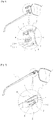
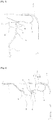
- the present invention provides a hinge piece (2) tightly inserted between end pieces (E) split at a distal end of the frames such that the hinge piece (2) protrudes, wherein the hinge piece (2) has a stopper groove (1) ; an elastic member (4) having an upper plate and a lower plate, wherein an intermediate portion of the upper plate is elastically bent, the upper plate and the lower plate have respective slots (3) to be doubly fitted onto the hinge piece (2), and the intermediate portion of the upper plate is bent at a predetermined angle to form a protrusion (6) in the horizontal direction; and a leg (T), the front end of which has a rotation pin (8) such that the front end of the leg (T) can be fitted into the stopper groove (1) of the hinge piece (2) while elastically pressing the upper plate of the elastic member (4), wherein the leg (T) has a relatively vertically elongate operating slot (5) at the front end thereof such that the legs (T) is rotatable about the rotation pin (8).
- the elastic member (4) is bent with the middle of a long formed plate material having elasticity so that the slots 3 are respectively formed in the upper plate of a top portion and the lower plate of a bottom portion, in which a lower plate slot 3-1 is formed to allow the split hinge piece 2 to be tightly inserted so that the hinge piece 2 can be fixed, and an upper plate slot 3-2 is formed to be slightly larger than the hinge piece 2 so that the hinge piece 2 can be easily inserted and separated.
- the slot 3-1 of the lower plate of the bottom portion functions to fix the hinge piece 2.
- the hinge piece 2 is respectively in each of the split end pieces E and is in close contact with the end pieces E when closely contacting the end pieces E.
- protrusions 6 that are bent at a predetermined angle in the middle of both sides of the upper plate slot 3-2 are formed in the elastic member 4 to give intermittent when the leg T is folded or unfolded.
- leg T when the leg T is folded or unfolded, if the leading portion 7 moves along the protrusion 6 at an angle greater than a certain angle, the leg T is rapidly folded or unfolded due to an action of a spring force.
- the stopper groove 1 of the hinge piece 2 is formed to have an entrance disposed downward rather than inward in which the rotation pin 8 is disposed so that the rotation pin 8 of the leg T may not be removed when fitted into the stopper groove 1.
- the elastic member 4 is fitted into the hinge piece 2
- the lower plate slot 31 is first fitted and is seated in the end piece E
- the upper plate slot 3-2 is fitted into an upper end portion of the hinge piece 2 so that the elastic member 4 may elastically move up and down.
- the slot 1 of the hinge piece 2 is exposed above the upper plate.
- the rotation pin 8 is inserted into the stopper groove 1 in a state where the hinge piece 2 passes through between the operating slot 5 of the leg T, the leg T is rotatably movable with respect to the rotation pin 8 and the stopper groove 1.
- the spring force rapidly increases and decreases, and thus the leg T is rapidly folded or unfolded. Since a direction of the spring force influencing the leading portion 7 of the leg T is changed by passing the protrusions 6, a force resisting to fold or unfold the leg T is applied before passing the protrusions 6, and an elastic force to fold or unfold the leg T is applied after passing the protrusions 6 so that a state in which the leg T is folded or unfolded is maintained.
- an operation of coupling the leg T to the glasses frame merely inserts the rotation pin 8 of the leg T into the stopper groove 1 having the entrance exposed by merely fitting and pressing the elastic member 4 into the hinge piece 2, thereby very simply and effectively assembling the glasses frame.
- the entrance of the stopper groove 1 formed in the hinge piece 2 is formed forward the glasses such that the rotation pin 8 of the leg T may be fitted in the front of the hinge piece 2.
- the entrance of the stopper groove 1 formed in the hinge piece 2 is formed backward the glasses such that the rotation pin 8 of the leg T may be fitted in the rear of the hinge piece 2.
- the entrance of the stopper groove 1 may be formed closer to a lower end of the hinge piece 2 than inward of the stopper groove 1 in which the rotation pin 8 is disposed such that the rotation pin 8 of the leading part of the leg T engaged into the stopper groove 1 is not easily escaped.
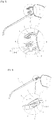
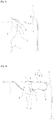
- FIG. 9 shows another embodiment of the present invention in which glasses frames are formed in a synthetic resin injection.
- the end piece E and the hinge piece 2 can be integrally formed by injection, and a groove d is formed around the hinge piece 2 in an inner side of the end piece E.
- the elastic member 4 is fitted into the hinge piece 2 by the stopper groove 3 so that a lower plate of the elastic member 4 is fitted into the groove d of the end piece E.
- FIG. 10 shows another embodiment in which the hinge piece 2 is formed of metal in the above other embodiment of the present invention, in which a coupling groove is formed in the end piece E during injection, a stopper protrusion is formed in a lower end of the hinge piece 2 so that the hinge piece 2 may be coupled by pressing the hinge piece 2 into the coupling groove after injection, and the lower end of the hinge piece 2 may be buried with injection resin and coupled to the end piece E during injection of the glasses frame.
- the end piece E and the hinge piece 2 of the glasses frame are integrally formed and thus a joint part of the leg T is not disconnected.
Landscapes
- Physics & Mathematics (AREA)
- Health & Medical Sciences (AREA)
- General Physics & Mathematics (AREA)
- Ophthalmology & Optometry (AREA)
- Optics & Photonics (AREA)
- Eyeglasses (AREA)
Claims (7)
- Brillengestell, einen vorderen Rahmen, Bügel (T) und eine Kopplungsstruktur umfassend, die zwischen den vorderen Rahmen und die Bügel (T) montiert ist, um den vorderen Rahmen und die Bügel (T) gelenkig zu koppeln, wobei der vordere Rahmen an jedem seiner seitlichen Enden ein gespaltenes Endstück (E) umfasst, wobei die Kopplungsstruktur Folgendes umfasst:zwei Gelenkstücke (2), wobei jedes Gelenkstück (2) straff zwischen den zwei Abschnitten des gespaltenen Endstücks (E) derart eingesetzt ist, dass jedes Gelenkstück (2) hervorsteht, wobei jedes Gelenkstück (2) eine Anschlagaussparung (1) aufweist,zwei elastische Elemente (4), die jeweils aus einem Plattenmaterial gebildet und im Wesentlichen zu einer U-Form mit einer oberen Platte, einer unteren Platte und einer Mitte mit Elastizität gebogen sind, wobei jedes elastische Element (4) Schlitze (3-1, 3-2) aufweist, die in der unteren Platte beziehungsweise der oberen Platte gebildet sind, wobei jedes elastische Element (4) zwischen einem entsprechenden vorderen Ende des Bügels (T) und einem entsprechenden Endstück (E) des vorderen Rahmens angeordnet ist, wo ein entsprechendes Gelenkstück (2) gehalten wird, wobei die obere Platte am vorderen Ende des Bügels (T) anliegt und die untere Platte am Endstück (E) des vorderen Rahmens anliegt, so dass das Gelenkstück (2) durch die Schlitze (3-1, 3-2) eingesetzt ist, undeinen Drehstift (8) und einen Funktionsschlitz (5), die am vorderen Ende jedes Bügels (T) gebildet sind, wobei das Gelenkstück (2) zwischen dem Funktionsschlitz (5) und dem Drehstift (8) hindurch verläuft, der in die Anschlagaussparung (1) eingesetzt ist, die parallel zur Längsrichtung der Bügel (T) und im Wesentlichen senkrecht zum Drehstift (8) ausgerichtet ist, so dass die Bügel (T) um den Drehstift (8) drehbar sind, wobei ein vorderer Abschnitt (7) jedes Bügels (T), der in einem festgelegten Winkel gebogen ist, an beiden Seiten über den Drehstift (8) hinausragt, wobei der vordere Abschnitt (7) in gleitendem Eingriff mit der oberen Platte des elastischen Elements (4) angeordnet ist und elastisch auf das elastische Element (4) drückt,gekennzeichnet durch die Tatsache, dass jedes elastische Element (4) ferner eine Auskragung (6) umfasst, die in einem festgelegten Winkel in der Mitte beider Seiten des oberen Plattenschlitzes (3-2) derart gebogen ist, das beim Auf- und Zuklappen des Bügels (T) eine Kraft ausgeübt wird, die dem Auf- oder Zuklappen des Bügels (T) entgegenwirkt, bevor die vorderen Abschnitte (7) durch die Auskragungen (6) verlaufen, und nach dem Durchlaufen der Auskragungen (6) eine elastische Kraft zum Auf- oder Zuklappen des Bügels (7) ausgeübt wird, so dass ein Zustand, in dem der Bügel (T) auf- oder zugeklappt ist, aufrechterhalten wird.
- Brillengestell, einen vorderen Rahmen, Bügel (T) und eine Kopplungsstruktur umfassend, die zwischen den vorderen Rahmen und die Bügel (T) montiert ist, um den vorderen Rahmen und die Bügel (T) gelenkig zu koppeln, wobei die Kopplungsstruktur Folgendes umfasst:zwei Gelenkstücke (2), wobei jedes Gelenkstück (2) aus der Innenseite eines Endstücks (E) hervorragt und durch Kunststoffharz-Spritzgießen einstückig mit dem Endstück (E) eines entfernten Endes des vorderen Rahmens gebildet ist, wobei jedes Gelenkstück (2) eine Anschlagaussparung (1) aufweist,zwei elastische Elemente (4), die jeweils aus einem Plattenmaterial gebildet und im Wesentlichen zu einer U-Form mit einer oberen Platte, einer unteren Platte und einer Mitte mit Elastizität gebogen sind, wobei jedes elastische Element (4) Schlitze (3-1, 3-2) aufweist, die in der unteren Platte beziehungsweise der oberen Platte gebildet sind, wobei jedes elastische Element (4) zwischen einem entsprechenden vorderen Ende des Bügels (T) und einem entsprechenden Endstück (E) des vorderen Rahmens angeordnet ist, wo ein entsprechendes Gelenkstück (2) gehalten wird, wobei die obere Platte am vorderen Ende des Bügels (T) anliegt und die untere Platte am Endstück (E) des vorderen Rahmens anliegt, so dass das Gelenkstück (2) durch die Schlitze (3-1, 3-2) eingesetzt ist, undeinen Drehstift (8) und einen Funktionsschlitz (5), die am vorderen Ende jedes Bügels (T) gebildet sind, wobei das Gelenkstück (2) zwischen dem Funktionsschlitz (5) und dem Drehstift (8) hindurch verläuft, der in die Anschlagaussparung (1) eingesetzt ist, die parallel zur Längsrichtung der Bügel (T) und im Wesentlichen senkrecht zum Drehstift (8) ausgerichtet ist, so dass die Bügel (T) um den Drehstift (8) drehbar sind, wobei ein vorderer Abschnitt (7) jedes Bügels (T), der in einem festgelegten Winkel gebogen ist, an beiden Seiten über den Drehstift (8) hinausragt, wobei der vordere Abschnitt (7) in gleitendem Eingriff mit der oberen Platte des elastischen Elements (4) angeordnet ist und elastisch auf das elastische Element (4) drückt,gekennzeichnet durch die Tatsache, dass jedes elastische Element (4) ferner eine Auskragung (6) umfasst, die in einem festgelegten Winkel in der Mitte beider Seiten des oberen Plattenschlitzes (3-2) derart gebogen ist, das beim Auf- und Zuklappen des Bügels (T) eine Kraft ausgeübt wird, die dem Auf- oder Zuklappen des Bügels (T) entgegenwirkt, bevor die vorderen Abschnitte (7) durch die Auskragungen (6) verlaufen, und nach dem Durchlaufen der Auskragungen (6) eine elastische Kraft zum Auf- oder Zuklappen des Bügels (7) ausgeübt wird, so dass ein Zustand, in dem der Bügel (T) auf- oder zugeklappt ist, aufrechterhalten wird.
- Brillengestell nach einem der Ansprüche 1 und 2, wobei ein Einlass der Anschlagaussparung (1) des Gelenkstücks (2) derart gebildet ist, dass er sich nach vorn öffnet.
- Brillengestell nach einem der Ansprüche 1 und 2, wobei ein Einlass der Anschlagaussparung (1) des Gelenkstücks (2) derart gebildet ist, dass er sich nach hinten öffnet.
- Brillengestell nach Anspruch 4, wobei der Einlass der Anschlagaussparung (1) näher an einem unteren Ende des Gelenkstücks (2) als einwärts der Anschlagaussparung (1) gebildet ist, in welcher der Drehstift (8) angeordnet ist.
- Brillengestell nach Anspruch 2, wobei das Gelenkstück (2) aus Metall gebildet ist, während des Spritzgießens eine Kopplungsaussparung in dem Endstück (E) gebildet wird und in einem unteren Ende des Gelenkstücks (2) eine Anschlagauskragung gebildet wird, so dass das Gelenkstück (2) mit dem Endstück (E) gekoppelt wird, indem die Anschlagauskragung nach dem Spritzgießen in die Kopplungsaussparung gepresst wird und das untere Ende des Gelenkstücks (2) in Spritzgussharz eingebettet und während des Spritzgießens des Rahmens mit dem Endstück (E) gekoppelt wird.
- Brillengestell nach Anspruch 2, wobei das Gelenkstück (2) und das Endstück (E) aus dem gleichen Kunstharz gebildet sind.
Applications Claiming Priority (3)
| Application Number | Priority Date | Filing Date | Title |
|---|---|---|---|
| KR1020100118424A KR101175034B1 (ko) | 2010-11-26 | 2010-11-26 | 안경테용 안경다리 결합 구조 |
| KR1020110122890A KR101315601B1 (ko) | 2011-11-23 | 2011-11-23 | 안경테와 안경다리 결합구조 |
| PCT/KR2011/009062 WO2012070907A2 (ko) | 2010-11-26 | 2011-11-25 | 안경테와 안경다리의 결합구조 |
Publications (3)
| Publication Number | Publication Date |
|---|---|
| EP2645153A2 EP2645153A2 (de) | 2013-10-02 |
| EP2645153A4 EP2645153A4 (de) | 2014-05-14 |
| EP2645153B1 true EP2645153B1 (de) | 2018-09-26 |
Family
ID=46146333
Family Applications (1)
| Application Number | Title | Priority Date | Filing Date |
|---|---|---|---|
| EP11843470.3A Active EP2645153B1 (de) | 2010-11-26 | 2011-11-25 | Struktur zur zusammenfügung eines rahmens und eines seitenbügels einer brille |
Country Status (3)
| Country | Link |
|---|---|
| US (1) | US20130239366A1 (de) |
| EP (1) | EP2645153B1 (de) |
| WO (1) | WO2012070907A2 (de) |
Cited By (2)
| Publication number | Priority date | Publication date | Assignee | Title |
|---|---|---|---|---|
| US11226495B2 (en) | 2019-01-28 | 2022-01-18 | Marchon Eyewear, Inc. | Screwless hinges for eyewear |
| EP4152080A1 (de) | 2021-09-21 | 2023-03-22 | Etnia Eyewear Culture, S.L. | Scharniersystem für brillen |
Families Citing this family (13)
| Publication number | Priority date | Publication date | Assignee | Title |
|---|---|---|---|---|
| WO2015109437A1 (zh) * | 2014-01-21 | 2015-07-30 | 华茂光学工业(厦门)有限公司 | 一种镜脚与镜框拆装结构 |
| FR3023385B1 (fr) * | 2014-07-04 | 2016-08-05 | Oxibis Group | Charniere d'une monture de lunettes |
| CN104634229A (zh) * | 2015-01-20 | 2015-05-20 | 东莞怡亿眼镜有限公司 | 一种眼镜倾角测量仪 |
| CN204422890U (zh) * | 2015-02-04 | 2015-06-24 | 景新(香港)有限公司 | 一种眼镜用弹性铰链 |
| CN104977731B (zh) * | 2015-07-20 | 2017-06-16 | 浙江工贸职业技术学院 | 一种带有蓝牙装置的眼镜 |
| ITUB20160923A1 (it) * | 2016-02-22 | 2017-08-22 | Safilo Sa Fabbrica Italiana Lavorazione Occhiali Spa | Montatura per occhiali |
| CN105739118B (zh) * | 2016-05-11 | 2019-08-02 | 温州益泰光学眼镜有限公司 | 镜腿的铰接结构及眼镜 |
| ITUA20163919A1 (it) * | 2016-05-30 | 2017-11-30 | Giorgio Spanio | "occhiale con cerniera elastica smontabile e stabilizzata, per astina rimovibile" |
| ES1158608Y (es) * | 2016-06-01 | 2016-09-09 | Hidalgo Aris Rubio | Montura desmontable para gafas |
| FR3069337B1 (fr) * | 2017-07-24 | 2019-08-23 | Parasite Design | Articulation de monture de lunettes |
| IT201900008262A1 (it) * | 2019-06-06 | 2020-12-06 | Safilo Spa | Montatura per occhiali |
| JP6764008B1 (ja) * | 2019-07-05 | 2020-09-30 | 軍司 重秋 | 眼鏡フレーム |
| US20220099998A1 (en) * | 2020-09-25 | 2022-03-31 | Shih-Yun Huang | Eyewear hinge device |
Family Cites Families (9)
| Publication number | Priority date | Publication date | Assignee | Title |
|---|---|---|---|---|
| US1729901A (en) * | 1925-01-17 | 1929-10-01 | Simonds Optical Company | Manufacture of spectacle frames |
| US2210507A (en) * | 1938-02-21 | 1940-08-06 | Spill Mfg Co Inc | Eyeglasses |
| US3145254A (en) * | 1962-04-02 | 1964-08-18 | Bausch & Lomb | Ophthalmic mounting |
| JP2001100159A (ja) * | 1999-09-30 | 2001-04-13 | Murai:Kk | 眼鏡の丁番構造 |
| JP2003215506A (ja) * | 2002-01-21 | 2003-07-30 | Koji Nagayoshi | 眼鏡のテンプル連結構造 |
| US6585372B1 (en) * | 2002-04-08 | 2003-07-01 | Koji Nagayoshi | Link structure between a temple arm and a bracket for eyeglasses |
| JP4414791B2 (ja) * | 2004-03-09 | 2010-02-10 | 株式会社佐々木セルロイド工業所 | 眼鏡のばね蝶番及びこの組立方法 |
| US6969173B1 (en) * | 2004-08-24 | 2005-11-29 | Sun Hing Optical Manufactory Limited | Spectacle frame with detachable arms |
| KR200380264Y1 (ko) * | 2005-01-11 | 2005-03-29 | 전천태 | 탄성 절곡부가 있는 안경테를 구비한 안경 |
-
2011
- 2011-11-25 EP EP11843470.3A patent/EP2645153B1/de active Active
- 2011-11-25 US US13/989,591 patent/US20130239366A1/en not_active Abandoned
- 2011-11-25 WO PCT/KR2011/009062 patent/WO2012070907A2/ko not_active Ceased
Non-Patent Citations (1)
| Title |
|---|
| None * |
Cited By (2)
| Publication number | Priority date | Publication date | Assignee | Title |
|---|---|---|---|---|
| US11226495B2 (en) | 2019-01-28 | 2022-01-18 | Marchon Eyewear, Inc. | Screwless hinges for eyewear |
| EP4152080A1 (de) | 2021-09-21 | 2023-03-22 | Etnia Eyewear Culture, S.L. | Scharniersystem für brillen |
Also Published As
| Publication number | Publication date |
|---|---|
| US20130239366A1 (en) | 2013-09-19 |
| WO2012070907A2 (ko) | 2012-05-31 |
| EP2645153A2 (de) | 2013-10-02 |
| WO2012070907A3 (ko) | 2012-09-27 |
| EP2645153A4 (de) | 2014-05-14 |
Similar Documents
| Publication | Publication Date | Title |
|---|---|---|
| EP2645153A2 (de) | Struktur zur zusammenfügung eines rahmens und eines seitenbügels einer brille | |
| CN211826763U (zh) | 眼镜 | |
| CN103676192B (zh) | 眼镜架与眼镜腿的连接构造 | |
| CN112313562B (zh) | 用于眼镜的柔性镜腿 | |
| US8474088B2 (en) | Windshield wiper | |
| JP4759056B2 (ja) | 2つの取替え可能なテンプルを有するタイプの眼鏡 | |
| KR101315601B1 (ko) | 안경테와 안경다리 결합구조 | |
| KR101417578B1 (ko) | 안경테와 안경다리의 연결구조체 | |
| CN104335105B (zh) | 具有装饰件的眼镜镜框 | |
| KR20160003369U (ko) | 힌지 개폐 구조를 갖는 화장품용기 | |
| KR20110005467U (ko) | 플라스틱안경테의 렌즈 및 안경다리 결합구조 | |
| US12443050B2 (en) | Snap-fit device for spectacle lens and spectacle frame | |
| US20190011726A1 (en) | Hinge for eyeglasses | |
| KR101664666B1 (ko) | 안경테의 안경다리 결합구조체 | |
| KR101965970B1 (ko) | 안경테와 안경다리의 결합 구조 | |
| KR101175034B1 (ko) | 안경테용 안경다리 결합 구조 | |
| KR101477040B1 (ko) | 안경테와 안경다리의 결합구조 | |
| CN109709689B (zh) | 用于眼镜框架的可拆卸弹性铰链 | |
| KR101531214B1 (ko) | 안경다리 및 연결구와 안경다리의 결합구조체 | |
| KR101232804B1 (ko) | 착탈식 안경다리 구조 | |
| KR20120124718A (ko) | 안경의 안경다리 연결구조 | |
| KR101846645B1 (ko) | 안경다리 연결구조체 | |
| KR101417573B1 (ko) | 안경테와 안경다리의 연결구조체 | |
| KR102605574B1 (ko) | 안경테와 안경다리의 연결구조체 | |
| KR20110008435U (ko) | 판스프링에 의해서 탄성을 가지는 합성수지 안경용 힌지 |
Legal Events
| Date | Code | Title | Description |
|---|---|---|---|
| PUAI | Public reference made under article 153(3) epc to a published international application that has entered the european phase |
Free format text: ORIGINAL CODE: 0009012 |
|
| 17P | Request for examination filed |
Effective date: 20130625 |
|
| AK | Designated contracting states |
Kind code of ref document: A2 Designated state(s): AL AT BE BG CH CY CZ DE DK EE ES FI FR GB GR HR HU IE IS IT LI LT LU LV MC MK MT NL NO PL PT RO RS SE SI SK SM TR |
|
| DAX | Request for extension of the european patent (deleted) | ||
| A4 | Supplementary search report drawn up and despatched |
Effective date: 20140414 |
|
| RIC1 | Information provided on ipc code assigned before grant |
Ipc: G02C 1/06 20060101ALI20140408BHEP Ipc: G02C 5/22 20060101AFI20140408BHEP Ipc: G02C 5/14 20060101ALI20140408BHEP |
|
| 17Q | First examination report despatched |
Effective date: 20170728 |
|
| GRAP | Despatch of communication of intention to grant a patent |
Free format text: ORIGINAL CODE: EPIDOSNIGR1 |
|
| INTG | Intention to grant announced |
Effective date: 20180405 |
|
| GRAS | Grant fee paid |
Free format text: ORIGINAL CODE: EPIDOSNIGR3 |
|
| GRAA | (expected) grant |
Free format text: ORIGINAL CODE: 0009210 |
|
| AK | Designated contracting states |
Kind code of ref document: B1 Designated state(s): AL AT BE BG CH CY CZ DE DK EE ES FI FR GB GR HR HU IE IS IT LI LT LU LV MC MK MT NL NO PL PT RO RS SE SI SK SM TR |
|
| REG | Reference to a national code |
Ref country code: GB Ref legal event code: FG4D |
|
| REG | Reference to a national code |
Ref country code: CH Ref legal event code: EP |
|
| REG | Reference to a national code |
Ref country code: AT Ref legal event code: REF Ref document number: 1046712 Country of ref document: AT Kind code of ref document: T Effective date: 20181015 |
|
| REG | Reference to a national code |
Ref country code: IE Ref legal event code: FG4D |
|
| REG | Reference to a national code |
Ref country code: DE Ref legal event code: R096 Ref document number: 602011052436 Country of ref document: DE |
|
| REG | Reference to a national code |
Ref country code: NL Ref legal event code: MP Effective date: 20180926 |
|
| PG25 | Lapsed in a contracting state [announced via postgrant information from national office to epo] |
Ref country code: GR Free format text: LAPSE BECAUSE OF FAILURE TO SUBMIT A TRANSLATION OF THE DESCRIPTION OR TO PAY THE FEE WITHIN THE PRESCRIBED TIME-LIMIT Effective date: 20181227 Ref country code: BG Free format text: LAPSE BECAUSE OF FAILURE TO SUBMIT A TRANSLATION OF THE DESCRIPTION OR TO PAY THE FEE WITHIN THE PRESCRIBED TIME-LIMIT Effective date: 20181226 Ref country code: NO Free format text: LAPSE BECAUSE OF FAILURE TO SUBMIT A TRANSLATION OF THE DESCRIPTION OR TO PAY THE FEE WITHIN THE PRESCRIBED TIME-LIMIT Effective date: 20181226 Ref country code: RS Free format text: LAPSE BECAUSE OF FAILURE TO SUBMIT A TRANSLATION OF THE DESCRIPTION OR TO PAY THE FEE WITHIN THE PRESCRIBED TIME-LIMIT Effective date: 20180926 Ref country code: LT Free format text: LAPSE BECAUSE OF FAILURE TO SUBMIT A TRANSLATION OF THE DESCRIPTION OR TO PAY THE FEE WITHIN THE PRESCRIBED TIME-LIMIT Effective date: 20180926 Ref country code: FI Free format text: LAPSE BECAUSE OF FAILURE TO SUBMIT A TRANSLATION OF THE DESCRIPTION OR TO PAY THE FEE WITHIN THE PRESCRIBED TIME-LIMIT Effective date: 20180926 Ref country code: SE Free format text: LAPSE BECAUSE OF FAILURE TO SUBMIT A TRANSLATION OF THE DESCRIPTION OR TO PAY THE FEE WITHIN THE PRESCRIBED TIME-LIMIT Effective date: 20180926 |
|
| REG | Reference to a national code |
Ref country code: LT Ref legal event code: MG4D |
|
| PG25 | Lapsed in a contracting state [announced via postgrant information from national office to epo] |
Ref country code: AL Free format text: LAPSE BECAUSE OF FAILURE TO SUBMIT A TRANSLATION OF THE DESCRIPTION OR TO PAY THE FEE WITHIN THE PRESCRIBED TIME-LIMIT Effective date: 20180926 Ref country code: LV Free format text: LAPSE BECAUSE OF FAILURE TO SUBMIT A TRANSLATION OF THE DESCRIPTION OR TO PAY THE FEE WITHIN THE PRESCRIBED TIME-LIMIT Effective date: 20180926 Ref country code: HR Free format text: LAPSE BECAUSE OF FAILURE TO SUBMIT A TRANSLATION OF THE DESCRIPTION OR TO PAY THE FEE WITHIN THE PRESCRIBED TIME-LIMIT Effective date: 20180926 |
|
| REG | Reference to a national code |
Ref country code: AT Ref legal event code: MK05 Ref document number: 1046712 Country of ref document: AT Kind code of ref document: T Effective date: 20180926 |
|
| PG25 | Lapsed in a contracting state [announced via postgrant information from national office to epo] |
Ref country code: EE Free format text: LAPSE BECAUSE OF FAILURE TO SUBMIT A TRANSLATION OF THE DESCRIPTION OR TO PAY THE FEE WITHIN THE PRESCRIBED TIME-LIMIT Effective date: 20180926 Ref country code: PL Free format text: LAPSE BECAUSE OF FAILURE TO SUBMIT A TRANSLATION OF THE DESCRIPTION OR TO PAY THE FEE WITHIN THE PRESCRIBED TIME-LIMIT Effective date: 20180926 Ref country code: NL Free format text: LAPSE BECAUSE OF FAILURE TO SUBMIT A TRANSLATION OF THE DESCRIPTION OR TO PAY THE FEE WITHIN THE PRESCRIBED TIME-LIMIT Effective date: 20180926 Ref country code: IS Free format text: LAPSE BECAUSE OF FAILURE TO SUBMIT A TRANSLATION OF THE DESCRIPTION OR TO PAY THE FEE WITHIN THE PRESCRIBED TIME-LIMIT Effective date: 20190126 Ref country code: CZ Free format text: LAPSE BECAUSE OF FAILURE TO SUBMIT A TRANSLATION OF THE DESCRIPTION OR TO PAY THE FEE WITHIN THE PRESCRIBED TIME-LIMIT Effective date: 20180926 Ref country code: IT Free format text: LAPSE BECAUSE OF FAILURE TO SUBMIT A TRANSLATION OF THE DESCRIPTION OR TO PAY THE FEE WITHIN THE PRESCRIBED TIME-LIMIT Effective date: 20180926 Ref country code: ES Free format text: LAPSE BECAUSE OF FAILURE TO SUBMIT A TRANSLATION OF THE DESCRIPTION OR TO PAY THE FEE WITHIN THE PRESCRIBED TIME-LIMIT Effective date: 20180926 Ref country code: RO Free format text: LAPSE BECAUSE OF FAILURE TO SUBMIT A TRANSLATION OF THE DESCRIPTION OR TO PAY THE FEE WITHIN THE PRESCRIBED TIME-LIMIT Effective date: 20180926 Ref country code: AT Free format text: LAPSE BECAUSE OF FAILURE TO SUBMIT A TRANSLATION OF THE DESCRIPTION OR TO PAY THE FEE WITHIN THE PRESCRIBED TIME-LIMIT Effective date: 20180926 |
|
| PG25 | Lapsed in a contracting state [announced via postgrant information from national office to epo] |
Ref country code: SK Free format text: LAPSE BECAUSE OF FAILURE TO SUBMIT A TRANSLATION OF THE DESCRIPTION OR TO PAY THE FEE WITHIN THE PRESCRIBED TIME-LIMIT Effective date: 20180926 Ref country code: PT Free format text: LAPSE BECAUSE OF FAILURE TO SUBMIT A TRANSLATION OF THE DESCRIPTION OR TO PAY THE FEE WITHIN THE PRESCRIBED TIME-LIMIT Effective date: 20190126 Ref country code: SM Free format text: LAPSE BECAUSE OF FAILURE TO SUBMIT A TRANSLATION OF THE DESCRIPTION OR TO PAY THE FEE WITHIN THE PRESCRIBED TIME-LIMIT Effective date: 20180926 |
|
| REG | Reference to a national code |
Ref country code: DE Ref legal event code: R097 Ref document number: 602011052436 Country of ref document: DE |
|
| REG | Reference to a national code |
Ref country code: CH Ref legal event code: PL |
|
| PG25 | Lapsed in a contracting state [announced via postgrant information from national office to epo] |
Ref country code: DK Free format text: LAPSE BECAUSE OF FAILURE TO SUBMIT A TRANSLATION OF THE DESCRIPTION OR TO PAY THE FEE WITHIN THE PRESCRIBED TIME-LIMIT Effective date: 20180926 Ref country code: LU Free format text: LAPSE BECAUSE OF NON-PAYMENT OF DUE FEES Effective date: 20181125 Ref country code: MC Free format text: LAPSE BECAUSE OF FAILURE TO SUBMIT A TRANSLATION OF THE DESCRIPTION OR TO PAY THE FEE WITHIN THE PRESCRIBED TIME-LIMIT Effective date: 20180926 |
|
| PLBE | No opposition filed within time limit |
Free format text: ORIGINAL CODE: 0009261 |
|
| STAA | Information on the status of an ep patent application or granted ep patent |
Free format text: STATUS: NO OPPOSITION FILED WITHIN TIME LIMIT |
|
| REG | Reference to a national code |
Ref country code: BE Ref legal event code: MM Effective date: 20181130 |
|
| REG | Reference to a national code |
Ref country code: IE Ref legal event code: MM4A |
|
| PG25 | Lapsed in a contracting state [announced via postgrant information from national office to epo] |
Ref country code: LI Free format text: LAPSE BECAUSE OF NON-PAYMENT OF DUE FEES Effective date: 20181130 Ref country code: CH Free format text: LAPSE BECAUSE OF NON-PAYMENT OF DUE FEES Effective date: 20181130 |
|
| 26N | No opposition filed |
Effective date: 20190627 |
|
| PG25 | Lapsed in a contracting state [announced via postgrant information from national office to epo] |
Ref country code: SI Free format text: LAPSE BECAUSE OF FAILURE TO SUBMIT A TRANSLATION OF THE DESCRIPTION OR TO PAY THE FEE WITHIN THE PRESCRIBED TIME-LIMIT Effective date: 20180926 Ref country code: IE Free format text: LAPSE BECAUSE OF NON-PAYMENT OF DUE FEES Effective date: 20181125 |
|
| PG25 | Lapsed in a contracting state [announced via postgrant information from national office to epo] |
Ref country code: BE Free format text: LAPSE BECAUSE OF NON-PAYMENT OF DUE FEES Effective date: 20181130 |
|
| PG25 | Lapsed in a contracting state [announced via postgrant information from national office to epo] |
Ref country code: MT Free format text: LAPSE BECAUSE OF NON-PAYMENT OF DUE FEES Effective date: 20181125 |
|
| PG25 | Lapsed in a contracting state [announced via postgrant information from national office to epo] |
Ref country code: TR Free format text: LAPSE BECAUSE OF FAILURE TO SUBMIT A TRANSLATION OF THE DESCRIPTION OR TO PAY THE FEE WITHIN THE PRESCRIBED TIME-LIMIT Effective date: 20180926 |
|
| PG25 | Lapsed in a contracting state [announced via postgrant information from national office to epo] |
Ref country code: HU Free format text: LAPSE BECAUSE OF FAILURE TO SUBMIT A TRANSLATION OF THE DESCRIPTION OR TO PAY THE FEE WITHIN THE PRESCRIBED TIME-LIMIT; INVALID AB INITIO Effective date: 20111125 Ref country code: MK Free format text: LAPSE BECAUSE OF NON-PAYMENT OF DUE FEES Effective date: 20180926 Ref country code: CY Free format text: LAPSE BECAUSE OF FAILURE TO SUBMIT A TRANSLATION OF THE DESCRIPTION OR TO PAY THE FEE WITHIN THE PRESCRIBED TIME-LIMIT Effective date: 20180926 |
|
| PGFP | Annual fee paid to national office [announced via postgrant information from national office to epo] |
Ref country code: GB Payment date: 20231110 Year of fee payment: 13 |
|
| PGFP | Annual fee paid to national office [announced via postgrant information from national office to epo] |
Ref country code: FR Payment date: 20231121 Year of fee payment: 13 |
|
| GBPC | Gb: european patent ceased through non-payment of renewal fee |
Effective date: 20241125 |
|
| PG25 | Lapsed in a contracting state [announced via postgrant information from national office to epo] |
Ref country code: GB Free format text: LAPSE BECAUSE OF NON-PAYMENT OF DUE FEES Effective date: 20241125 |
|
| PG25 | Lapsed in a contracting state [announced via postgrant information from national office to epo] |
Ref country code: FR Free format text: LAPSE BECAUSE OF NON-PAYMENT OF DUE FEES Effective date: 20241130 |
|
| PGFP | Annual fee paid to national office [announced via postgrant information from national office to epo] |
Ref country code: DE Payment date: 20251127 Year of fee payment: 15 |