EP2645002A2 - Hausgerätebedienvorrichtung - Google Patents
Hausgerätebedienvorrichtung Download PDFInfo
- Publication number
- EP2645002A2 EP2645002A2 EP13159854.2A EP13159854A EP2645002A2 EP 2645002 A2 EP2645002 A2 EP 2645002A2 EP 13159854 A EP13159854 A EP 13159854A EP 2645002 A2 EP2645002 A2 EP 2645002A2
- Authority
- EP
- European Patent Office
- Prior art keywords
- control electronics
- electronics board
- unit
- domestic appliance
- control
- Prior art date
- Legal status (The legal status is an assumption and is not a legal conclusion. Google has not performed a legal analysis and makes no representation as to the accuracy of the status listed.)
- Granted
Links
Images


Classifications
-
- F—MECHANICAL ENGINEERING; LIGHTING; HEATING; WEAPONS; BLASTING
- F24—HEATING; RANGES; VENTILATING
- F24C—DOMESTIC STOVES OR RANGES ; DETAILS OF DOMESTIC STOVES OR RANGES, OF GENERAL APPLICATION
- F24C7/00—Stoves or ranges heated by electric energy
- F24C7/08—Arrangement or mounting of control or safety devices
Definitions
- control electronics board units are arranged in a row next to each other on a common control electronics carrier unit or on different control electronics carrier units.
- the object of the invention is, in particular, to further develop a household appliance operating device.
- the object is achieved by the features of claim 1, while advantageous embodiments and modifications of the invention can be taken from the dependent claims.
- control electronics board unit should be understood in this context, in particular an electronic unit having at least one board, preferably exactly one board, and disposed on the board electronic components and which is in particular part of an operating unit of the home appliance operating device having domestic appliance.
- circuit board should be understood in particular to mean a unit which has a carrier body, in particular a plate-like carrier body, of an electrically insulating material on which conductor tracks of an electrically conductive material are arranged and preferably fastened.
- An electrically insulating material is to be understood as meaning in particular a material which has a specific electrical resistance of at least 10 9 ⁇ m, in particular of at least 10 10 ⁇ m, preferably of at least 10 11 ⁇ m and particularly advantageously of at least 10 12 ⁇ m at 20 ° C.
- An "electrically conductive material” is to be understood in this context in particular as meaning a material having a specific electrical conductivity of at least 10 3 S / m, in particular of at least 10 4 S / m, preferably of at least 10 5 S / at 20 ° C. m and particularly advantageous of at least 10 6 S / m.
- a "control electronics carrier unit” should be understood in particular to mean a unit which is provided for this purpose, at least one control electronics board unit to wear. The control electronics carrier unit is preferably designed differently from a part of a housing unit, in particular a part of an outer housing unit. By “intended” is intended to be understood in particular specially designed and / or equipped.
- control electronics board units are mounted "in lines one above the other" in an assembled state should in particular be understood to mean that when viewing the two control electronics board units from one operating area, the two control electronics board units are arranged one above the other in a plane parallel to a main extension plane of at least one of the two control electronics board units are.
- a "main extension plane" of a structural unit is to be understood in particular as meaning a plane which is parallel to a largest side surface of a smallest geometric cuboid which just completely surrounds the structural unit, and in particular runs through the center of this cuboid.
- an "operating area” is to be understood as meaning, in particular, a spatial area in which an operator stays with a proper and / or intended operation of the household appliance.
- the operating area is characterized by a spatial arrangement of at least one operating unit, in particular a user interface, and / or by at least one lettering and / or marking of at least one operating unit.
- a "user interface” is understood to mean a surface that can be touched in an assembled state by an operator and that is provided for operation by means of a touch and / or approach.
- longitudinal directions of the control electronics board units are arranged at least substantially parallel to one another and are preferably aligned at least substantially parallel to a row direction.
- a "longitudinal direction" of a structural unit should be understood as meaning, in particular, a direction which is arranged parallel to a longest edge of a smallest geometric cuboid which just completely encloses the structural unit.
- two directions are “at least substantially parallel to each other” should be understood in particular that the directions include a minimum angle, which is a maximum of 15 °, in particular at most 10 °, preferably at most 5 ° and more preferably at most 1 °.
- a "row direction” is to be understood in particular as meaning a direction parallel to a main extension plane of at least one control electronics board unit, which is perpendicular to at least a shortest line connecting the two control electronics board units in a vertical projection of the control electronics board units on the main extension plane.
- the control electronics board units can be mounted on the operating electronics carrier unit in any manner that appears appropriate to a person skilled in the art, in particular by means of a screw connection and preferably by a latching connection.
- a domestic appliance operating device can advantageously be further developed.
- a mounting can be advantageously optimized, since a pre-assembly of the two control electronics board units on the control electronics carrier unit can be made possible.
- an advantageous utilization of an available installation space can be achieved, in particular in the case of a domestic appliance designed as a hob.
- a number of control electronics board units can be increased.
- a plurality of touch-sliders in particular at least four and preferably at least five touch-sliders, can be used.
- a "touch slider” is to be understood as meaning, in particular, an operating unit which can be operated by sliding a finger of an operator on a preferably correspondingly marked user interface, wherein in at least one operating state by the sliding of the finger on the operating surface, in particular an increment or decrementing a manipulated variable, in particular a heating stage, takes place.
- the user interface may in particular be curved, for example, at least partially annular, be formed. Preferably, however, the user interface is at least substantially rectilinear.
- the user interface is designed "to at least a large part rectilinearly" is to be understood in particular as meaning that an edge line of the user interface taken together has a length of at least 60%, in particular at least 70%, preferably at least 80% and particularly advantageously at least 90% of a total length of the edge line is rectilinear.
- a flexibility in placing the control electronics board units can be increased advantageously, in particular, different layouts can be accomplished thanks to the flexibility.
- the control electronics board units can, in particular despite the limited space, be placed on an intuitive and ergonomic for an operator ergonomic place on the appliance, especially on the hob.
- control electronics board units comprises at least one touch sensor and / or proximity sensor.
- both control electronics board units each have at least one contact and / or proximity sensor.
- a "touch and / or proximity sensor” is to be understood in this context, in particular a sensor unit, which is intended to contact a member of the sensor unit and / or an approach to an element of the sensor unit, in particular by a finger of an operator detect.
- the sensor unit comprises a sensor element of an electrically conductive material and is intended to detect a contact of the sensor element and / or an approach to the sensor element, preferably by measuring a change in an electrical capacitance of the sensor element.
- At least one of the control electronics board units comprises at least a plurality of contact and / or proximity sensors arranged side by side in at least one row.
- a "plurality" of contact and / or proximity sensors should in particular be understood as meaning at least two contact and / or proximity sensors.
- the fact that the touch and / or proximity sensors are arranged "in at least one row next to one another" should in particular mean that at least one straight line parallel to the row direction exists, which at least is perpendicular to a vertical extension of the contact and / or proximity sensors one of the control electronics board units intersects the plurality of touch and / or proximity sensors. In this way, a clear arrangement of the touch and / or proximity sensors can be achieved. Furthermore, further operating functions can be opened.
- a minimum horizontal distance of the two touch and / or proximity sensors is at most 10 mm, in particular at most 7.5 mm, preferably at most 5 mm, and particularly advantageously at most 2.5 mm. This makes a user comfort particularly advantageous be increased. Furthermore, a particularly advantageous operating functionality can be developed.
- control electronics carrier unit is integrally formed.
- in one piece should be understood in particular to be at least materially bonded, for example by a welding process, an adhesive process, an injection process and / or another process that appears expedient to a person skilled in the art, and / or advantageously shaped in one piece, for example by manufacture from a single cast and / or by a production in a single or multi-component injection molding process and advantageously from a single blank.
- the control electronics carrier unit at least partially, preferably to a large extent and particularly advantageously completely made of a plastic.
- control electronics carrier unit "consists to a large extent" of a plastic is to be understood in this context to mean that the control electronics carrier unit has a mass fraction of at least 60%, in particular at least 70%, preferably at least 80% and particularly advantageously at least 90% made of a plastic. As a result, a variety of components can be reduced. Furthermore, a production of the control electronics carrier unit can be advantageously simplified.
- the domestic appliance control device has at least one further control electronics board unit, which is arranged in an assembled state in at least one row next to at least one of the two control electronics board units.
- the fact that the further control electronics board unit is arranged "in at least one row next to" at least one of the two control electronics board units should in particular be understood to mean that at least one straight line parallel to the line direction exists, which in a vertical projection of the control electronics board units on a main extension plane another control electronics board unit which cuts at least one of the two control electronics board units and the further control electronics board unit.
- the household appliance operating device advantageously comprises at least one further operating electronics carrier unit, to which the further operating electronic board unit in one assembled state is mounted.
- the further control electronics board unit can be mounted on any, the skilled person seems appropriate sense on the other control electronics carrier unit, in particular by means of a screw connection and preferably also by a latching connection.
- the domestic appliance operating device has at least one control panel, which, viewed in an assembled state from an operating area, is arranged at least partially in front of the control electronics board units.
- a "control panel” is to be understood in this context, in particular a unit which forms an outer wall of the domestic appliance in an assembled state and at least provides a user interface on the outer wall.
- the control panel is at least partially, preferably for the most part and particularly advantageously completely made of an electrically insulating material, in particular a glass ceramic.
- control panel consists to a large extent" of an electrically insulating material
- control panel with a mass fraction of at least 60%, in particular of at least 70%, preferably of at least 80% and particularly advantageous of at least 90% consists of an electrically insulating material.
- control panel is arranged "in front of the control electronics board units" from an operating area should in particular mean that at least one beam exists for each of the two control electronics board units, which starts from at least one surface point of the respective control electronics board unit and against penetration into the operating area the control panel cuts. In this way, an advantageous protection for the control electronics board units can be created. In particular, penetration of dirt and / or moisture can be at least largely avoided. Furthermore, a user-friendly operating unit can be provided.
- the domestic appliance operating device has a hob plate, with which the control panel is integrally formed, an advantageously simple embodiment of a hob can be achieved. Furthermore, a cleaning effort can be reduced. In particular, this can also create an attractive design.
- a domestic appliance in particular a hob, proposed with a domestic appliance operating device according to the invention.
- a total width of all control electronics carrier units mounted in the household appliance is at most 90 cm, in particular at most 80 cm and preferably at most 70 cm.
- FIG. 1 shows a cooking appliance 44 designed as a household appliance in a plan view.
- the cooktop 44 may be formed as any cooktop 44, but preferably, as in the present case, as an induction cooktop 46.
- the cooktop 44 includes a home appliance operating device designed as a cooktop operating device 10.
- the cooktop operating device 10 comprises a cooktop panel 42.
- the cooktop panel 42 comprises a base plate made of a glass ceramic.
- the hob plate 42 is arranged horizontally in an installed position of the hob 44 and provided for setting up cooking utensils (not shown) for heating purposes.
- heating zones 48a-e are marked on the hob plate 42 in a known manner. In the present case, the hob 44 has five heating zones 48a-e.
- the hob plate 42 is formed integrally with a control panel 40.
- touch-sensitive controls 50 are marked in a known manner, of which only one example is designated.
- a touch slider 30, 32, 34, 52, 54 is marked for each heating zone 48a-e.
- the touch sliders 30, 32, 34, 52, 54 are each provided for setting a power level for heating the respective associated heating zone 48a-e.
- the touch slider 30, 32, 34, 52, 54 are formed at least substantially rectangular in a vertical viewing on a main extension plane of the hob plate 42.
- a longitudinal direction of the touch sliders 30, 32, 34, 52, 54 is formed parallel to a longitudinal direction 56 of the hob plate 42.
- a touch slider 30 is arranged in a line 18 parallel to the line 20.
- the line 18 in the main extension plane of the hob plate 42 is arranged above the line 20.
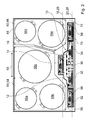
- FIG. 2 shows the hob 44 with disassembled cooking plate 42 in a plan view.
- Each of the heating zones 48a-e is associated with a heating unit 58a-e of the cooktop 44 below the cooktop panel 42.
- the heating units 58a-e may be any heating units 58a-e that appear appropriate to the person skilled in the art, but preferably, as in the present case, induction heating units.
- Each of the heating units 58a-e has at least one heating element and may in particular also comprise a plurality of heating elements, preferably concentrically arranged (not shown).
- the heating units 58a-e are attached to plate-like components 60, 62 of the cooktop 44 in any manner that appears appropriate to a person skilled in the art.
- the components 60, 62 are formed as shielding elements 64, 66.
- the shielding elements 64, 66 consist of an at least largely nonmagnetic metal, preferably of aluminum.
- the components 60, 62 are fastened to an outer housing 68 of the cooking field 44 in any manner that appears appropriate to a person skilled in the art.
- the outer housing 68 viewed in the longitudinal direction 56, has an extension of less than 80 cm.
- the power electronics unit comprises at least one inverter for generating a high-frequency alternating current for the heating units 58a-e.
- the control panel 40 is in an assembled state from the operating area 41, as viewed from control electronics board units 14, 16, 36, 70 are arranged (see also FIG. 1 ).
- the control electronics board units 14, 36, 70 are identical to each other.
- the control electronics board units 14, 36, 70 are at least substantially rectangular when viewed perpendicular to a respective main extension plane educated.
- the control electronics board units 14, 36, 70 each have a plurality of juxtaposed in a row 28, 29 proximity sensors 22a-g, wherein the proximity sensors 22a-g in FIG. 2 not for the sake of clarity and in FIG. 3 are shown only in the case of the control electronics board unit 14.
- the proximity sensors 22a-g of the control electronics board unit 14 are part of the touch slider 30.
- the proximity sensors of the control electronics board unit 36 are part of the touch slider 52.
- the proximity sensors of the control electronics board unit 70 are part of the touch slider 54.
- the control electronics board unit 16 is of the control electronics board units 14th , 36, 70 differently formed.
- the control electronics board unit 16 is formed at least substantially in the form of a rectangle when viewed perpendicular to its main extension plane, wherein the rectangle is widened in a central region perpendicular to a long side edge of the rectangle.
- An extension of the control electronics board unit 16 in the longitudinal direction 56 is significantly larger than and in particular more than twice as large as a corresponding extent of the control electronics board units 14, 36, 70.
- the control electronics board unit 16 comprises a plurality of proximity sensors 24a-g, 26a arranged side by side in the line 28 -G.
- the proximity sensors 24a-g are part of the touch slider 32.
- the proximity sensors 26a-g are part of the touch slider 34.
- the proximity sensors 22a-g, 24a-g, 26a-g of the control electronics board units 14, 16, 36, 70 Detect in a known manner in each case a touch of the control panel 40 in an area above the respective proximity sensor 22a-g, 24a-g, 26a-g.
- a sliding direction of a finger of an operator via the respective associated touch slider can be determined by a time sequence of activation of the proximity sensors 22a-g, 24a-g, 26a-g 30, 32, 34, 52, 54 are determined. Further, based on a time between the activation of a proximity sensor 22a-g, 24a-g, 26a-g and a proximity sensor 22a-g, 24a-g, 26a-g adjacent to this proximity sensor 22a-g, 24a-g, 26a-g a sliding speed of the finger on the respectively associated touch-slider 30, 32, 34, 52, 54 are determined.
- the hob control device 10 includes control electronics carrier units 12, 38, 74, which fix the control electronics board units 14, 16, 36, 70 in an assembled state.
- the control electronics board units 14, 16, 36, 70 can be attached to the control electronics carrier units 12, 38, 74 in any manner that appears appropriate to the person skilled in the art.
- the control electronics carrier units 12, 38, 74 comprise latching elements 76a-f, which are provided to fix the control electronics board units 14, 16, 36, 70 in each case by means of a latching connection.
- the locking elements 76a-f in FIG. 2 not and in FIG.
- the control electronics carrier units 12, 38, 74 are each integrally formed.
- the control electronics carrier units 12, 38, 74 each consist of a plastic.
- the control electronics carrier units 38, 74 are formed at least substantially rectangular in a vertical viewing on a respective main extension plane.
- the control electronics carrier unit 12 is formed at a vertical view on its main extension plane at least substantially in the form of a trapezoid, wherein legs of the trapezoid are stepped.
- the control electronics board unit 36 is fixed in a mounted state on the control electronics carrier unit 38.
- the control electronics board unit 70 is fixed in a mounted state on the control electronics carrier unit 74.
- the control electronics board units 14, 16 are mounted together in an assembled state on the control electronics carrier unit 12.
- the control electronics board units 14, 16 are mounted in an assembled state in lines 18, 20 one above the other on the control electronics carrier unit 12.
- the control electronics carrier units 12, 38, 74 are arranged flush with each other in a mounted state on a side facing the operating area 41.
- the control electronics carrier unit 12 is arranged in a mounted state between the control electronics carrier units 38, 74.
- the control electronics carrier units 38, 74 are furthermore arranged relative to the control electronics carrier unit 12 such that the proximity sensors 24a-g, 26a-g of the control electronics board units 16, 36, 70 are arranged along the line 28.
- the control electronics board unit 36 is arranged in a mounted state in the line 20 next to the control electronics board unit 16.
- more or fewer than five heating zones may be provided.
- three fixed heating zones and a variable heating area may be provided with heating units arranged in a matrix.
- only a variable heating area, in particular with matrix-like arranged heating units is provided.
- touch sliders are conceivable.
- touch sliders may have more or less than seven proximity sensors.
- touch-slider with only two proximity sensors are conceivable.
Landscapes
- Engineering & Computer Science (AREA)
- Chemical & Material Sciences (AREA)
- Combustion & Propulsion (AREA)
- Mechanical Engineering (AREA)
- General Engineering & Computer Science (AREA)
- Induction Heating Cooking Devices (AREA)
- Cookers (AREA)
- Electric Ovens (AREA)
- Electric Stoves And Ranges (AREA)
Abstract
Description
- Bei bekannten Induktionskochfeldern sind Bedienelektronikplatineneinheiten in einer Zeile nebeneinander auf einer gemeinsamen Bedienelektronikträgereinheit oder auch auf unterschiedlichen Bedienelektronikträgereinheiten angeordnet.
- Die Aufgabe der Erfindung besteht insbesondere darin, eine Hausgerätebedienvorrichtung vorteilhaft weiterzuentwickeln. Die Aufgabe wird erfindungsgemäß durch die Merkmale des Patentanspruchs 1 gelöst, während vorteilhafte Ausgestaltungen und Weiterbildungen der Erfindung den Unteransprüchen entnommen werden können.
- Es wird eine Hausgerätebedienvorrichtung, insbesondere eine Kochfeldbedienvorrichtung, mit zumindest einer Bedienelektronikträgereinheit und wenigstens zwei Bedienelektronikplatineneinheiten vorgeschlagen, welche in einem montierten Zustand in Zeilen übereinander auf der Bedienelektronikträgereinheit montiert sind. Unter einer "Bedienelektronikplatineneinheit" soll in diesem Zusammenhang insbesondere eine elektronische Einheit verstanden werden, welche wenigstens eine Platine, vorzugsweise genau eine Platine, und auf der Platine angeordnete elektronische Bauteile aufweist und welche insbesondere Teil einer Bedieneinheit eines die Hausgerätebedienvorrichtung aufweisenden Hausgeräts ist. Unter einer "Platine" soll insbesondere eine Einheit verstanden werden, welche einen Trägerkörper, insbesondere einen plattenartigen Trägerkörper, aus einem elektrisch isolierenden Material aufweist, an welchem Leiterbahnen aus einem elektrisch leitenden Material angeordnet und vorzugsweise befestigt sind. Unter einem elektrisch isolierenden Material soll insbesondere ein Material verstanden werden, welches bei 20°C einen spezifischen elektrischen Widerstand von zumindest 109 Ωm, insbesondere von wenigstens 1010 Ωm, vorzugsweise von mindestens 1011 Ωm und besonders vorteilhaft von zumindest 1012 Ωm aufweist. Unter einem "elektrisch leitenden Material" soll in diesem Zusammenhang insbesondere ein Material verstanden werden, welches bei 20°C eine spezifische elektrische Leitfähigkeit von zumindest 103 S/m, insbesondere von wenigstens 104 S/m, vorzugsweise von mindestens 105 S/m und besonders vorteilhaft von zumindest 106 S/m aufweist. Unter einer "Bedienelektronikträgereinheit" soll insbesondere eine Einheit verstanden werden, welche dazu vorgesehen ist, zumindest eine Bedienelektronikplatineneinheit zu tragen. Die Bedienelektronikträgereinheit ist vorzugsweise von einem Teil einer Gehäuseeinheit, insbesondere einem Teil einer Außengehäuseeinheit, verschieden ausgebildet. Unter "vorgesehen" soll insbesondere speziell ausgelegt und/oder ausgestattet verstanden werden.
- Darunter, dass die Bedienelektronikplatineneinheiten in einem montierten Zustand "in Zeilen übereinander" montiert sind, soll insbesondere verstanden werden, dass bei einer Betrachtung der zwei Bedienelektronikplatineneinheiten von einem Bedienbereich aus die zwei Bedienelektronikplatineneinheiten in einer zu einer Haupterstreckungsebene wenigstens einer der zwei Bedienelektronikplatineneinheiten parallelen Ebene übereinander angeordnet sind. Unter einer "Haupterstreckungsebene" einer Baueinheit soll insbesondere eine Ebene verstanden werden, welche parallel zu einer größten Seitenfläche eines kleinsten geometrischen Quaders ist, welcher die Baueinheit gerade noch vollständig umschließt, und insbesondere durch den Mittelpunkt dieses Quaders verläuft. Unter einem "Bedienbereich" soll in diesem Zusammenhang insbesondere ein räumlicher Bereich verstanden werden, in welchem sich ein Bediener bei einer vorschriftsmäßigen und/oder vorgesehenen Bedienung des Hausgeräts aufhält. Insbesondere ist der Bedienbereich durch eine räumliche Anordnung wenigstens einer Bedieneinheit, insbesondere einer Bedienoberfläche, und/oder durch zumindest eine Beschriftung und/oder Markierung zumindest einer Bedieneinheit gekennzeichnet. Unter einer "Bedienoberfläche" soll in diesem Zusammenhang eine in einem montierten Zustand durch einen Bediener anfassbare Oberfläche verstanden werden, welche zu einer Bedienung mittels einer Berührung und/oder Annäherung vorgesehen ist. Vorzugsweise sind Längsrichtungen der Bedienelektronikplatineneinheiten zumindest im Wesentlichen parallel zueinander angeordnet und vorzugsweise zumindest im Wesentlichen parallel zu einer Zeilenrichtung ausgerichtet. Unter einer "Längsrichtung" einer Baueinheit soll in diesem Zusammenhang insbesondere eine Richtung verstanden werden, welche parallel angeordnet ist zu einer längsten Kante eines kleinsten geometrischen Quaders, welcher die Baueinheit gerade noch vollständig umschließt. Darunter, dass zwei Richtungen "zumindest im Wesentlichen parallel zueinander" sind, soll insbesondere verstanden werden, dass die Richtungen einen kleinsten Winkel einschließen, welcher maximal 15°, insbesondere höchstens 10°, vorzugsweise maximal 5° und besonders vorteilhaft höchstens 1° beträgt. Unter einer "Zeilenrichtung" soll insbesondere eine zu einer Haupterstreckungsebene wenigstens einer Bedienelektronikplatineneinheit parallele Richtung verstanden werden, welche senkrecht ist zu wenigstens einer kürzesten Verbindungslinie der zwei Bedienelektronikplatineneinheiten bei einer senkrechten Projektion der Bedienelektronikplatineneinheiten auf die Haupterstreckungsebene. Die Bedienelektronikplatineneinheiten können auf beliebige, dem Fachmann als sinnvoll erscheinende Art an der Bedienelektronikträgereinheit montiert sein, insbesondere mittels einer Schraubverbindung und vorzugsweise durch eine Rastverbindung.
- Durch eine solche Ausgestaltung kann eine Hausgerätebedienvorrichtung vorteilhaft weiterentwickelt werden. Insbesondere kann eine Montage vorteilhaft optimiert werden, da eine Vormontage der zwei Bedienelektronikplatineneinheiten an der Bedienelektronikträgereinheit ermöglicht werden kann. Ferner kann eine vorteilhafte Ausnutzung eines verfügbaren Bauraums erreicht werden, insbesondere bei einem als Kochfeld ausgebildeten Hausgerät. So kann insbesondere bei begrenztem Bauraum eine Anzahl von Bedienelektronikplatineneinheiten erhöht werden. Insbesondere kann eine Mehrzahl von Touch-Slidern, insbesondere zumindest vier und vorzugsweise wenigstens fünf Touch-Slider, zum Einsatz kommen. Unter einem "Touch-Slider" soll in diesem Zusammenhang insbesondere eine Bedieneinheit verstanden werden, welche durch ein Gleiten eines Fingers eines Bedieners auf einer vorzugsweise entsprechend gekennzeichneten Bedienoberfläche bedienbar ist, wobei in wenigstens einem Betriebszustand durch das Gleiten des Fingers auf der Bedienoberfläche insbesondere ein Inkrementieren oder Dekrementieren einer Stellgröße, insbesondere einer Heizstufe, erfolgt. Die Bedienoberfläche kann insbesondere gekrümmt, beispielsweise zumindest teilweise kreisringförmig, ausgebildet sein. Vorzugsweise ist die Bedienoberfläche jedoch zu wenigstens einem Großteil geradlinig ausgebildet. Darunter, dass die Bedienoberfläche "zu wenigstens einem Großteil geradlinig" ausgebildet ist, soll insbesondere verstanden werden, dass eine Randlinie der Bedienoberfläche zusammengenommen auf einer Länge von zumindest 60 %, insbesondere von mindestens 70 %, vorzugsweise von wenigstens 80 % und besonders vorteilhaft von zumindest 90 % einer Gesamtlänge der Randlinie geradlinig ist. Des Weiteren kann eine Flexibilität bei einer Platzierung der Bedienelektronikplatineneinheiten vorteilhaft gesteigert werden, wobei insbesondere verschiedene Layouts dank der Flexibilität bewerkstelligt werden können. Die Bedienelektronikplatineneinheiten können, insbesondere trotz des begrenzten Bauraums, an einem für einen Bediener intuitiv einsichtigen und ergonomischen Ort am Hausgerät, insbesondere am Kochfeld, platziert werden.
- In einer bevorzugten Ausgestaltung der Erfindung wird vorgeschlagen, dass wenigstens eine der Bedienelektronikplatineneinheiten zumindest einen Berühr- und/oder Annäherungssensor umfasst. Vorzugsweise weisen beide Bedienelektronikplatineneinheiten jeweils zumindest einen Berühr- und/oder Annäherungssensor auf. Unter einem "Berühr- und/oder Annäherungssensor" soll in diesem Zusammenhang insbesondere eine Sensoreinheit verstanden werden, welche dazu vorgesehen ist, eine Berührung eines Elements der Sensoreinheit und/oder eine Annäherung an ein Element der Sensoreinheit, insbesondere durch einen Finger eines Bedieners, zu detektieren. Vorzugsweise umfasst die Sensoreinheit ein Sensorelement aus einem elektrisch leitenden Material und ist dazu vorgesehen, eine Berührung des Sensorelements und/oder eine Annäherung an das Sensorelement zu detektieren, vorzugsweise durch Messung einer Veränderung einer elektrischen Kapazität des Sensorelements. Hierdurch kann ein Bedienkomfort vorteilhaft gesteigert werden.
- In einer besonders bevorzugten Ausgestaltung der Erfindung wird vorgeschlagen, dass wenigstens eine der Bedienelektronikplatineneinheiten zumindest eine Mehrzahl von in zumindest einer Zeile nebeneinander angeordneten Berühr- und/oder Annäherungssensoren umfasst. Unter einer "Mehrzahl" von Berühr- und/oder Annäherungssensoren sollen insbesondere zumindest zwei Berühr- und/oder Annäherungssensoren verstanden werden. Darunter, dass die Berühr- und/oder Annäherungssensoren "in zumindest einer Zeile nebeneinander" angeordnet sind, soll insbesondere verstanden werden, dass wenigstens eine zur Zeilenrichtung parallele Gerade existiert, welche bei einer senkrechten Projektion der Berühr- und/oder Annäherungssensoren auf eine Haupterstreckungsebene wenigstens einer der Bedienelektronikplatineneinheiten die Mehrzahl der Berühr- und/oder Annäherungssensoren schneidet. Hierdurch kann eine übersichtliche Anordnung der Berühr- und/oder Annäherungssensoren erreicht werden. Ferner können weitere Bedienfunktionalitäten eröffnet werden.
- Ferner wird vorgeschlagen, dass wenigstens zwei der Berühr- und/oder Annäherungssensoren in einem montierten Zustand Teil eines Touch-Sliders sind. Vorzugsweise beträgt ein minimaler horizontaler Abstand der zwei Berühr- und/oder Annäherungssensoren höchstens 10 mm, insbesondere maximal 7,5 mm, vorzugsweise höchstens 5 mm und besonders vorteilhaft maximal 2,5 mm. Hierdurch kann ein Bedienkomfort besonders vorteilhaft gesteigert werden. Ferner kann eine besonders vorteilhafte Bedienfunktionalität erschlossen werden.
- Vorteilhaft ist die Bedienelektronikträgereinheit einstückig ausgebildet. Unter "einstückig" soll insbesondere zumindest stoffschlüssig verbunden verstanden werden, beispielsweise durch einen Schweißprozess, einen Klebeprozess, einen Anspritzprozess und/oder einen anderen, dem Fachmann als sinnvoll erscheinenden Prozess, und/oder vorteilhaft in einem Stück geformt verstanden werden wie beispielsweise durch eine Herstellung aus einem Guss und/oder durch eine Herstellung in einem Ein- oder Mehrkomponentenspritzverfahren und vorteilhaft aus einem einzelnen Rohling. Vorzugsweise besteht die Bedienelektronikträgereinheit zumindest teilweise, vorzugsweise zu einem Großteil und besonders vorteilhaft vollständig aus einem Kunststoff. Darunter, dass die Bedienelektronikträgereinheit "zu einem Großteil" aus einem Kunststoff besteht, soll in diesem Zusammenhang insbesondere verstanden werden, dass die Bedienelektronikträgereinheit mit einem Massenanteil von zumindest 60 %, insbesondere von wenigstens 70 %, vorzugsweise von mindestens 80 % und besonders vorteilhaft von zumindest 90 % aus einem Kunststoff besteht. Hierdurch kann eine Bauteilevielfalt reduziert werden. Ferner kann eine Herstellung der Bedienelektronikträgereinheit vorteilhaft vereinfacht werden.
- In einer weiteren Ausgestaltung der Erfindung wird vorgeschlagen, dass die Hausgerätebedienvorrichtung wenigstens eine weitere Bedienelektronikplatineneinheit aufweist, welche in einem montierten Zustand in zumindest einer Zeile neben wenigstens einer der zwei Bedienelektronikplatineneinheiten angeordnet ist. Darunter, dass die weitere Bedienelektronikplatineneinheit in einem montierten Zustand "in zumindest einer Zeile neben" wenigstens einer der zwei Bedienelektronikplatineneinheiten angeordnet ist, soll insbesondere verstanden werden, dass wenigstens eine zur Zeilenrichtung parallele Gerade existiert, welche bei einer senkrechten Projektion der Bedienelektronikplatineneinheiten auf eine Haupterstreckungsebene der weiteren Bedienelektronikplatineneinheit die wenigstens eine der zwei Bedienelektronikplatineneinheiten und die weitere Bedienelektronikplatineneinheit schneidet. Hierdurch kann eine vorteilhafte Bauraumausnutzung erreicht werden. Insbesondere kann ein Bauraumbedarf in Zeilenrichtung reduziert werden.
- Vorteilhaft umfasst die Hausgerätebedienvorrichtung wenigstens eine weitere Bedienelektronikträgereinheit, an welcher die weitere Bedienelektronikplatineneinheit in einem montierten Zustand montiert ist. Auch die weitere Bedienelektronikplatineneinheit kann auf beliebige, dem Fachmann als sinnvoll erscheinende Art an der weiteren Bedienelektronikträgereinheit montiert sein, insbesondere mittels einer Schraubverbindung und vorzugsweise ebenfalls durch eine Rastverbindung. Hierdurch kann ein modulares Design verwirklicht werden, wodurch eine Flexibilität in einer Produktentwicklung vorteilhaft gesteigert werden kann.
- Ferner wird vorgeschlagen, dass die Hausgerätebedienvorrichtung wenigstens eine Bedienblende aufweist, welche in einem montierten Zustand von einem Bedienbereich aus betrachtet zumindest teilweise vor den Bedienelektronikplatineneinheiten angeordnet ist. Unter einer "Bedienblende" soll in diesem Zusammenhang insbesondere eine Einheit verstanden werden, welche in einem montierten Zustand eine Außenwand des Hausgeräts bildet und an der Außenwand zumindest eine Bedienoberfläche bereitstellt. Vorzugsweise besteht die Bedienblende zumindest teilweise, vorzugsweise zu einem Großteil und besonders vorteilhaft vollständig aus einem elektrisch isolierenden Material, insbesondere einer Glaskeramik. Darunter, dass die Bedienblende "zu einem Großteil" aus einem elektrisch isolierenden Material besteht, soll in diesem Zusammenhang insbesondere verstanden werden, dass die Bedienblende mit einem Massenanteil von zumindest 60 %, insbesondere von wenigstens 70 %, vorzugsweise von mindestens 80 % und besonders vorteilhaft von zumindest 90 % aus einem elektrisch isolierenden Material besteht. Darunter, dass die Bedienblende von einem Bedienbereich aus betrachtet "vor den Bedienelektronikplatineneinheiten" angeordnet ist, soll insbesondere verstanden werden, dass für die zwei Bedienelektronikplatineneinheiten jeweils zumindest ein Strahl existiert, welcher von wenigstens einem Oberflächenpunkt der jeweiligen Bedienelektronikplatineneinheit startet und vor einem Eindringen in den Bedienbereich die Bedienblende schneidet. Hierdurch kann ein vorteilhafter Schutz für die Bedienelektronikplatineneinheiten geschaffen werden. Insbesondere kann ein Eindringen von Schmutz und/oder Feuchtigkeit zumindest weitgehend vermieden werden. Ferner kann eine komfortabel bedienbare Bedieneinheit bereitgestellt werden.
- Wenn die Hausgerätebedienvorrichtung eine Kochfeldplatte aufweist, mit welcher die Bedienblende einstückig ausgebildet ist, kann eine vorteilhaft einfache Ausgestaltung eines Kochfelds erreicht werden. Ferner kann ein Reinigungsaufwand reduziert werden. Insbesondere kann hierdurch auch ein ansprechendes Design geschaffen werden.
- Ferner wird ein Hausgerät, insbesondere ein Kochfeld, mit einer erfindungsgemäßen Hausgerätebedienvorrichtung vorgeschlagen. Vorzugsweise beträgt eine Gesamtbreite aller im Hausgerät montierten Bedienelektronikträgereinheiten höchstens 90 cm, insbesondere maximal 80 cm und vorzugsweise höchstens 70 cm. Hierdurch kann ein vorteilhaft geringer Bauraumbedarf erreicht werden.
- Weitere Vorteile ergeben sich aus der folgenden Zeichnungsbeschreibung. In der Zeichnung ist ein Ausführungsbeispiel der Erfindung dargestellt. Die Zeichnung, die Beschreibung und die Ansprüche enthalten zahlreiche Merkmale in Kombination. Der Fachmann wird die Merkmale zweckmäßigerweise auch einzeln betrachten und zu sinnvollen weiteren Kombinationen zusammenfassen.
- Es zeigen:
- Fig. 1
- ein Kochfeld mit einer Kochfeldbedienvorrichtung in einer Draufsicht,
- Fig. 2
- das Kochfeld bei demontierter Kochfeldplatte in einer Draufsicht und
- Fig. 3
- einen Teil der Kochfeldbedienvorrichtung in einer vergrößerten Ansicht.
-
Figur 1 zeigt ein als Kochfeld 44 ausgebildetes Hausgerät in einer Draufsicht. Das Kochfeld 44 kann als beliebiges Kochfeld 44 ausgebildet sein, vorzugsweise jedoch wie im vorliegenden Fall als ein Induktionskochfeld 46. Das Kochfeld 44 umfasst eine als Kochfeldbedienvorrichtung 10 ausgebildete Hausgerätebedienvorrichtung. Die Kochfeldbedienvorrichtung 10 umfasst eine Kochfeldplatte 42. Die Kochfeldplatte 42 umfasst eine Grundplatte aus einer Glaskeramik. Die Kochfeldplatte 42 ist in einer Einbaulage des Kochfelds 44 horizontal angeordnet und zu einem Aufstellen von Gargeschirr (nicht dargestellt) zu Heizzwecken vorgesehen. Hierzu sind auf der Kochfeldplatte 42 in bekannter Weise Heizzonen 48a-e markiert. Im vorliegenden Fall weist das Kochfeld 44 fünf Heizzonen 48a-e auf. Die Kochfeldplatte 42 ist einstückig mit einer Bedienblende 40 ausgebildet. Auf der Bedienblende 40 sind in bekannter Weise berührungsempfindliche Bedienelemente 50 markiert, von denen beispielhaft lediglich eines bezeichnet ist. Auf der Bedienblende 40 ist für jede Heizzone 48a-e ein Touch-Slider 30, 32, 34, 52, 54 markiert. Die Touch-Slider 30, 32, 34, 52, 54 sind jeweils zu einer Einstellung einer Leistungsstufe für eine Beheizung der jeweils zugeordneten Heizzone 48a-e vorgesehen. Die Touch-Slider 30, 32, 34, 52, 54 sind bei einer senkrechten Betrachtung auf eine Haupterstreckungsebene der Kochfeldplatte 42 zumindest im Wesentlichen rechteckig ausgebildet. Eine Längsrichtung der Touch-Slider 30, 32, 34, 52, 54 ist parallel zu einer Längsrichtung 56 der Kochfeldplatte 42 ausgebildet. Vier der Touch-Slider 32, 34, 52, 54 sind in einer Zeile 20 angeordnet. Ein Touch-Slider 30 ist in einer zur Zeile 20 parallelen Zeile 18 angeordnet. Bei einer Betrachtung von einem Bedienbereich 41 aus ist die Zeile 18 in der Haupterstreckungsebene der Kochfeldplatte 42 über der Zeile 20 angeordnet. -
Figur 2 zeigt das Kochfeld 44 bei demontierter Kochfeldplatte 42 in einer Draufsicht. Jeder der Heizzonen 48a-e ist unterhalb der Kochfeldplatte 42 eine Heizeinheit 58a-e des Kochfelds 44 zugeordnet. Bei den Heizeinheiten 58a-e kann es sich um beliebige, dem Fachmann als sinnvoll erscheinende Heizeinheiten 58a-e handeln, vorzugsweise jedoch, wie im vorliegenden Fall, um Induktionsheizeinheiten. Jede der Heizeinheiten 58a-e weist zumindest ein Heizelement auf und kann insbesondere auch mehrere, vorzugsweise konzentrisch angeordnete Heizelemente umfassen (nicht dargestellt). Die Heizeinheiten 58a-e sind auf eine beliebige, dem Fachmann als sinnvoll erscheinende Art an plattenartigen Bauelementen 60, 62 des Kochfelds 44 befestigt. Im vorliegenden Fall des Induktionskochfelds 46 sind die Bauelemente 60, 62 als Abschirmelemente 64, 66 ausgebildet. Die Abschirmelemente 64, 66 bestehen aus einem zumindest weitgehend unmagnetischen Metall, vorzugsweise aus Aluminium. Die Bauelemente 60, 62 sind auf eine beliebige, dem Fachmann als sinnvoll erscheinende Art an einem Außengehäuse 68 des Kochfelds 44 befestigt. Das Außengehäuse 68 weist in Längsrichtung 56 betrachtet eine Erstreckung von weniger als 80 cm auf. Zwischen den Bauelementen 60, 62 und dem Außengehäuse 68 ist eine inFigur 2 nicht dargestellte Leistungselektronikeinheit des Kochfelds 44 angeordnet, welche dazu vorgesehen ist, die Heizeinheiten 58a-e mit Energie zu versorgen. Im vorliegenden Fall des Induktionskochfelds 46 umfasst die Leistungselektronikeinheit zumindest einen Wechselrichter zu einer Erzeugung eines hochfrequenten Wechselstroms für die Heizeinheiten 58a-e. - Die Bedienblende 40 ist in einem montierten Zustand vom Bedienbereich 41 aus betrachtet vor Bedienelektronikplatineneinheiten 14, 16, 36, 70 angeordnet (vgl. hierzu auch
Figur 1 ). Die Bedienelektronikplatineneinheiten 14, 36, 70 sind miteinander identisch ausgebildet. Die Bedienelektronikplatineneinheiten 14, 36, 70 sind bei einer senkrechten Betrachtung auf eine jeweilige Haupterstreckungsebene zumindest im Wesentlichen rechteckig ausgebildet. Die Bedienelektronikplatineneinheiten 14, 36, 70 weisen jeweils eine Mehrzahl von in einer Zeile 28, 29 nebeneinander angeordneten Annäherungssensoren 22a-g auf, wobei die Annäherungssensoren 22a-g inFigur 2 der Übersichtlichkeit halber nicht und inFigur 3 lediglich für den Fall der Bedienelektronikplatineneinheit 14 dargestellt sind. Die Annäherungssensoren 22a-g der Bedienelektronikplatineneinheit 14 sind Teil des Touch-Sliders 30. Die Annäherungssensoren der Bedienelektronikplatineneinheit 36 sind Teil des Touch-Sliders 52. Die Annäherungssensoren der Bedienelektronikplatineneinheit 70 sind Teil des Touch-Sliders 54. Die Bedienelektronikplatineneinheit 16 ist von den Bedienelektronikplatineneinheiten 14, 36, 70 verschieden ausgebildet. Die Bedienelektronikplatineneinheit 16 ist bei einer senkrechten Betrachtung auf ihre Haupterstreckungsebene zumindest weitgehend in Form eines Rechtecks ausgebildet, wobei das Rechteck in einem mittleren Bereich senkrecht zu einer langen Seitenkante des Rechtecks verbreitert ist. Eine Erstreckung der Bedienelektronikplatineneinheit 16 in Längsrichtung 56 ist deutlich größer als und insbesondere mehr als doppelt so groß wie eine entsprechende Erstreckung der Bedienelektronikplatineneinheiten 14, 36, 70.Die Bedienelektronikplatineneinheit 16 umfasst eine Mehrzahl von in der Zeile 28 nebeneinander angeordneten Annäherungssensoren 24a-g, 26a-g. Die Annäherungssensoren 24a-g sind dabei Teil des Touch-Sliders 32. Die Annäherungssensoren 26a-g sind hingegen Teil des Touch-Sliders 34. Die Annäherungssensoren 22a-g, 24a-g, 26a-g der Bedienelektronikplatineneinheiten 14, 16, 36, 70 detektieren in bekannter Weise jeweils eine Berührung der Bedienblende 40 in einem Bereich oberhalb des jeweiligen Annäherungssensors 22a-g, 24a-g, 26a-g. Mittels jeweils einer Steuereinheit (nicht dargestellt) der Bedienelektronikplatineneinheiten 14, 16, 36, 70 kann anhand eines zeitlichen Ablaufs einer Aktivierung der Annäherungssensoren 22a-g, 24a-g, 26a-g eine Gleitrichtung eines Fingers eines Bedieners über den jeweils zugeordneten Touch-Slider 30, 32, 34, 52, 54 ermittelt werden. Ferner kann anhand einer Zeit zwischen der Aktivierung eines Annäherungssensors 22a-g, 24a-g, 26a-g und eines zu diesem Annäherungssensor 22a-g, 24a-g, 26a-g benachbarten Annäherungssensors 22a-g, 24a-g, 26a-g eine Gleitgeschwindigkeit des Fingers über den jeweils zugeordneten Touch-Slider 30, 32, 34, 52, 54 ermittelt werden. Sowohl die Gleitrichtung als auch die Gleitgeschwindigkeit kann von der jeweiligen Steuereinheit zur Auslösung eines Steuerereignisses, insbesondere zur Einstellung der Heizstufe der zugeordneten Heizeinheit 58a-e, berücksichtigt werden. Die Kochfeldbedienvorrichtung 10 umfasst Bedienelektronikträgereinheiten 12, 38, 74, welche die Bedienelektronikplatineneinheiten 14, 16, 36, 70 in einem montierten Zustand fixieren. Die Bedienelektronikplatineneinheiten 14, 16, 36, 70 können dabei auf beliebige, dem Fachmann als sinnvoll erscheinende Weise an den Bedienelektronikträgereinheiten 12, 38, 74 befestigt sein. Im vorliegenden Fall umfassen die Bedienelektronikträgereinheiten 12, 38, 74 Rastelemente 76a-f, welche dazu vorgesehen sind, die Bedienelektronikplatineneinheiten 14, 16, 36, 70 jeweils mittels einer Rastverbindung zu fixieren. Der Übersichtlichkeit halber sind die Rastelemente 76a-f inFigur 2 nicht und inFigur 3 lediglich für die Bedienelektronikträgereinheit 12 dargestellt. Die Bedienelektronikträgereinheiten 12, 38, 74 sind jeweils einstückig ausgebildet. Die Bedienelektronikträgereinheiten 12, 38, 74 bestehen jeweils aus einem Kunststoff. Die Bedienelektronikträgereinheiten 38, 74 sind bei einer senkrechten Betrachtung auf eine jeweilige Haupterstreckungsebene zumindest im Wesentlichen rechteckig ausgebildet. Die Bedienelektronikträgereinheit 12 ist bei einer senkrechten Betrachtung auf ihre Haupterstreckungsebene zumindest im Wesentlichen in Form eines Trapezes ausgebildet, wobei Schenkel des Trapezes gestuft sind. Die Bedienelektronikplatineneinheit 36 ist in einem montierten Zustand an der Bedienelektronikträgereinheit 38 fixiert. Die Bedienelektronikplatineneinheit 70 ist in einem montierten Zustand an der Bedienelektronikträgereinheit 74 fixiert. Die Bedienelektronikplatineneinheiten 14, 16 sind in einem montierten Zustand zusammen an der Bedienelektronikträgereinheit 12 montiert. Die Bedienelektronikplatineneinheiten 14, 16 sind in einem montierten Zustand in Zeilen 18, 20 übereinander auf der Bedienelektronikträgereinheit 12 montiert. Die Bedienelektronikträgereinheiten 12, 38, 74 sind in einem montierten Zustand auf einer dem Bedienbereich 41 zugewandten Seite miteinander bündig angeordnet. Die Bedienelektronikträgereinheit 12 ist in einem montierten Zustand zwischen den Bedienelektronikträgereinheiten 38, 74 angeordnet. Die Bedienelektronikträgereinheiten 38, 74 sind ferner derart relativ zur Bedienelektronikträgereinheit 12 angeordnet, dass die Annäherungssensoren 24a-g, 26a-g der Bedienelektronikplatineneinheiten 16, 36, 70 entlang der Zeile 28 angeordnet sind. Somit ist insbesondere die Bedienelektronikplatineneinheit 36 in einem montierten Zustand in der Zeile 20 neben der Bedienelektronikplatineneinheit 16 angeordnet. - In alternativen Ausgestaltungen können auch mehr oder weniger als fünf Heizzonen vorgesehen sein. Insbesondere können beispielsweise auch drei feste Heizzonen und ein variabler Heizbereich mit matrixartig angeordneten Heizeinheiten vorgesehen sein. Ferner ist auch denkbar, dass lediglich ein variabler Heizbereich, insbesondere mit matrixartig angeordneten Heizeinheiten, vorgesehen ist. Des Weiteren sind alternative Ausgestaltungen von Touch-Slidern denkbar. Insbesondere können Touch-Slider über mehr oder weniger als sieben Annäherungssensoren verfügen. Insbesondere sind Touch-Slider mit lediglich zwei Annäherungssensoren denkbar.
-
10 Kochfeldbedienvorrichtung 58 Heizeinheit 12 Bedienelektronikträgereinheit 60 Bauelement 14 Bedienelektronikplatineneinheit 62 Bauelement 16 Bedienelektronikplatineneinheit 64 Abschirmelement 18 Zeile 66 Abschirmelement 20 Zeile 68 Außengehäuse 22 Annäherungssensor 70 Bedienelektronikplatineneinheit 24 Annäherungssensor 74 Bedienelektronikträgereinheit 26 Annäherungssensor 76 Rastelement 28 Zeile 29 Zeile 30 Touch-Slider 32 Touch-Slider 34 Touch-Slider 36 Bedienelektronikplatineneinheit 38 Bedienelektronikträgereinheit 40 Bedienblende 41 Bedienbereich 42 Kochfeldplatte 44 Kochfeld 46 Induktionskochfeld 48 Heizzone 50 Bedienelement 52 Touch-Slider 54 Touch-Slider 56 Längsrichtung
Claims (10)
- Hausgerätebedienvorrichtung, insbesondere Kochfeldbedienvorrichtung (10), mit zumindest einer Bedienelektronikträgereinheit (12) und wenigstens zwei Bedienelektronikplatineneinheiten (14, 16), welche in einem montierten Zustand in Zeilen (18, 20) übereinander auf der Bedienelektronikträgereinheit (12) montiert sind.
- Hausgerätebedienvorrichtung nach Anspruch 1, dadurch gekennzeichnet, dass wenigstens eine der Bedienelektronikplatineneinheiten (14, 16) zumindest einen Berühr- und/oder Annäherungssensor (22a-g, 24a-g, 26a-g) umfasst.
- Hausgerätebedienvorrichtung nach Anspruch 1 oder 2, dadurch gekennzeichnet, dass wenigstens eine der Bedienelektronikplatineneinheiten (14, 16) zumindest eine Mehrzahl von in zumindest einer Zeile (28, 29) nebeneinander angeordneten Berühr- und/oder Annäherungssensoren (22a-g, 24a-g, 26a-g) umfasst.
- Hausgerätebedienvorrichtung nach Anspruch 3, dadurch gekennzeichnet, dass wenigstens zwei der Berühr- und/oder Annäherungssensoren (22a-g, 24a-g, 26a-g) in einem montierten Zustand Teil eines Touch-Sliders (30, 32, 34) sind.
- Hausgerätebedienvorrichtung nach einem der vorhergehenden Ansprüche, dadurch gekennzeichnet, dass die Bedienelektronikträgereinheit (12) einstückig ausgebildet ist.
- Hausgerätebedienvorrichtung nach einem der vorhergehenden Ansprüche, gekennzeichnet durch wenigstens eine weitere Bedienelektronikplatineneinheit (36), welche in einem montierten Zustand in zumindest einer Zeile (20) neben wenigstens einer der zwei Bedienelektronikplatineneinheiten (16) angeordnet ist.
- Hausgerätebedienvorrichtung nach Anspruch 6, gekennzeichnet durch wenigstens eine weitere Bedienelektronikträgereinheit (38), an welcher die weitere Bedienelektronikplatineneinheit (36) in einem montierten Zustand montiert ist.
- Hausgerätebedienvorrichtung nach einem der vorhergehenden Ansprüche, gekennzeichnet durch wenigstens eine Bedienblende (40), welche in einem montierten Zustand von einem Bedienbereich (41) aus betrachtet zumindest teilweise vor den Bedienelektronikplatineneinheiten (14, 16) angeordnet ist.
- Hausgerätebedienvorrichtung nach Anspruch 8, gekennzeichnet durch eine Kochfeldplatte (42), mit welcher die Bedienblende (40) einstückig ausgebildet ist.
- Hausgerät, insbesondere Kochfeld (44), mit einer Hausgerätebedienvorrichtung nach einem der vorhergehenden Ansprüche.
Applications Claiming Priority (1)
| Application Number | Priority Date | Filing Date | Title |
|---|---|---|---|
| ES201230497 | 2012-03-30 |
Publications (3)
| Publication Number | Publication Date |
|---|---|
| EP2645002A2 true EP2645002A2 (de) | 2013-10-02 |
| EP2645002A3 EP2645002A3 (de) | 2016-06-15 |
| EP2645002B1 EP2645002B1 (de) | 2021-05-12 |
Family
ID=47997047
Family Applications (1)
| Application Number | Title | Priority Date | Filing Date |
|---|---|---|---|
| EP13159854.2A Active EP2645002B1 (de) | 2012-03-30 | 2013-03-19 | Kochfeld |
Country Status (2)
| Country | Link |
|---|---|
| EP (1) | EP2645002B1 (de) |
| ES (1) | ES2884933T3 (de) |
Cited By (1)
| Publication number | Priority date | Publication date | Assignee | Title |
|---|---|---|---|---|
| DE102016213004A1 (de) * | 2016-07-15 | 2018-01-18 | BSH Hausgeräte GmbH | Bedienmodul für ein Kochfeld |
Family Cites Families (10)
| Publication number | Priority date | Publication date | Assignee | Title |
|---|---|---|---|---|
| JPS5347572U (de) * | 1976-09-28 | 1978-04-22 | ||
| DE4419866A1 (de) * | 1994-06-07 | 1995-12-14 | Ego Elektro Blanc & Fischer | Steuerungsanordnung für ein Elektrowärmegerät |
| JP3311608B2 (ja) * | 1996-10-18 | 2002-08-05 | シャープ株式会社 | 加熱調理器 |
| KR100502935B1 (ko) * | 2003-01-11 | 2005-07-21 | 삼성전자주식회사 | 전자레인지 및 그 제어 장치 |
| KR100672575B1 (ko) * | 2004-10-15 | 2007-01-24 | 엘지전자 주식회사 | 전기레인지용 컨트롤 어셈블리 |
| DE102006030549A1 (de) * | 2006-07-03 | 2008-01-17 | BSH Bosch und Siemens Hausgeräte GmbH | Halterung für ein Elektronikmodul |
| EP3385623B1 (de) * | 2006-08-26 | 2022-10-12 | Electrolux Home Products Corporation N.V. | Herd mit einer bedien- und anzeigeeinheit |
| KR101025935B1 (ko) * | 2008-07-22 | 2011-03-30 | 엘지전자 주식회사 | 가열조리기기 및 그의 조립방법 |
| EP2192350A1 (de) * | 2008-11-15 | 2010-06-02 | Electrolux Home Products Corporation N.V. | Steuertafel zur Steuerung mehrerer unterschiedlicher Funktionen einer Anwendung |
| WO2011090223A1 (ko) * | 2010-01-21 | 2011-07-28 | 엘지전자 주식회사 | 전자레인지의 컨트롤 패널 |
-
2013
- 2013-03-19 EP EP13159854.2A patent/EP2645002B1/de active Active
- 2013-03-19 ES ES13159854T patent/ES2884933T3/es active Active
Non-Patent Citations (1)
| Title |
|---|
| None |
Cited By (1)
| Publication number | Priority date | Publication date | Assignee | Title |
|---|---|---|---|---|
| DE102016213004A1 (de) * | 2016-07-15 | 2018-01-18 | BSH Hausgeräte GmbH | Bedienmodul für ein Kochfeld |
Also Published As
| Publication number | Publication date |
|---|---|
| EP2645002B1 (de) | 2021-05-12 |
| ES2884933T3 (es) | 2021-12-13 |
| EP2645002A3 (de) | 2016-06-15 |
Similar Documents
| Publication | Publication Date | Title |
|---|---|---|
| EP2614308B1 (de) | Hausgerätebedienvorrichtung | |
| DE102013022100A1 (de) | Berührungs- und/oder annäherungsempfindliche Eingabevorrichtung | |
| DE102004024835B3 (de) | Sensoranordnung für eine Pseudokontinuierliche Betätigung | |
| DE102014018470A1 (de) | Berührungs- und/oder annäherungsempfindliche Bedienvorrichtung | |
| DE102010006777A1 (de) | Kapazitiver Berührungs- und/oder Annäherungsschalter | |
| DE102012219265A1 (de) | Hausgerätevorrichtung | |
| EP3092444B1 (de) | Hausgerätebedienvorrichtung | |
| EP0950860A2 (de) | Kochfeld mit Bedienbereich | |
| EP3513124A1 (de) | Vorrichtung zur bedienung eines kücheneinbaugerätes | |
| EP2256416B1 (de) | Trägeranordnung | |
| DE102012219264A1 (de) | Hausgerätevorrichtung | |
| EP2645002B1 (de) | Kochfeld | |
| EP2578948A1 (de) | Hausgerätvorrichtung mit zumindest einer Trägereinheit und zumindest einer Befestigungseinheit zu einer seitlichen Befestigung | |
| DE102013213032A1 (de) | Kochfeld | |
| WO2006015724A1 (de) | Kapazitiver berührungsschalter für eine bedieneinrichtung eines elektrogerätes, bedieneinrichtung sowie verfahren zur auswertung | |
| EP1188990A2 (de) | Einbaukochmulde | |
| EP2348638B1 (de) | Kapazitiver Berührungs- und/oder Annäherungsschalter | |
| DE102013202238A1 (de) | Haushaltsgerätebaureihe und Verfahren zum Herstellen unterschiedlich zu bedienender Haushaltsgeräte | |
| DE102013207787B4 (de) | Kochfeldvorrichtung | |
| EP2156706A1 (de) | Kochfeld | |
| DE102008041517A1 (de) | Hausgerätevorrichtung | |
| EP2770640B1 (de) | Bedienvorrichtung, insbesondere für ein elektronisches Haushaltsgerät | |
| EP2703725B1 (de) | Kochfeldvorrichtung | |
| EP2600064B1 (de) | Bedienvorrichtung | |
| EP2703726B1 (de) | Kochfeldvorrichtung |
Legal Events
| Date | Code | Title | Description |
|---|---|---|---|
| PUAI | Public reference made under article 153(3) epc to a published international application that has entered the european phase |
Free format text: ORIGINAL CODE: 0009012 |
|
| AK | Designated contracting states |
Kind code of ref document: A2 Designated state(s): AL AT BE BG CH CY CZ DE DK EE ES FI FR GB GR HR HU IE IS IT LI LT LU LV MC MK MT NL NO PL PT RO RS SE SI SK SM TR |
|
| AX | Request for extension of the european patent |
Extension state: BA ME |
|
| RAP1 | Party data changed (applicant data changed or rights of an application transferred) |
Owner name: BSH HAUSGERAETE GMBH |
|
| PUAL | Search report despatched |
Free format text: ORIGINAL CODE: 0009013 |
|
| AK | Designated contracting states |
Kind code of ref document: A3 Designated state(s): AL AT BE BG CH CY CZ DE DK EE ES FI FR GB GR HR HU IE IS IT LI LT LU LV MC MK MT NL NO PL PT RO RS SE SI SK SM TR |
|
| AX | Request for extension of the european patent |
Extension state: BA ME |
|
| RIC1 | Information provided on ipc code assigned before grant |
Ipc: F24C 7/08 20060101AFI20160509BHEP |
|
| STAA | Information on the status of an ep patent application or granted ep patent |
Free format text: STATUS: REQUEST FOR EXAMINATION WAS MADE |
|
| 17P | Request for examination filed |
Effective date: 20161215 |
|
| RBV | Designated contracting states (corrected) |
Designated state(s): AL AT BE BG CH CY CZ DE DK EE ES FI FR GB GR HR HU IE IS IT LI LT LU LV MC MK MT NL NO PL PT RO RS SE SI SK SM TR |
|
| STAA | Information on the status of an ep patent application or granted ep patent |
Free format text: STATUS: EXAMINATION IS IN PROGRESS |
|
| 17Q | First examination report despatched |
Effective date: 20180810 |
|
| GRAP | Despatch of communication of intention to grant a patent |
Free format text: ORIGINAL CODE: EPIDOSNIGR1 |
|
| STAA | Information on the status of an ep patent application or granted ep patent |
Free format text: STATUS: GRANT OF PATENT IS INTENDED |
|
| INTG | Intention to grant announced |
Effective date: 20201217 |
|
| GRAS | Grant fee paid |
Free format text: ORIGINAL CODE: EPIDOSNIGR3 |
|
| GRAA | (expected) grant |
Free format text: ORIGINAL CODE: 0009210 |
|
| STAA | Information on the status of an ep patent application or granted ep patent |
Free format text: STATUS: THE PATENT HAS BEEN GRANTED |
|
| AK | Designated contracting states |
Kind code of ref document: B1 Designated state(s): AL AT BE BG CH CY CZ DE DK EE ES FI FR GB GR HR HU IE IS IT LI LT LU LV MC MK MT NL NO PL PT RO RS SE SI SK SM TR |
|
| REG | Reference to a national code |
Ref country code: GB Ref legal event code: FG4D Free format text: NOT ENGLISH |
|
| REG | Reference to a national code |
Ref country code: CH Ref legal event code: EP |
|
| REG | Reference to a national code |
Ref country code: DE Ref legal event code: R096 Ref document number: 502013015711 Country of ref document: DE |
|
| REG | Reference to a national code |
Ref country code: NL Ref legal event code: FP |
|
| REG | Reference to a national code |
Ref country code: IE Ref legal event code: FG4D Free format text: LANGUAGE OF EP DOCUMENT: GERMAN |
|
| REG | Reference to a national code |
Ref country code: AT Ref legal event code: REF Ref document number: 1392420 Country of ref document: AT Kind code of ref document: T Effective date: 20210615 |
|
| REG | Reference to a national code |
Ref country code: LT Ref legal event code: MG9D |
|
| PG25 | Lapsed in a contracting state [announced via postgrant information from national office to epo] |
Ref country code: FI Free format text: LAPSE BECAUSE OF FAILURE TO SUBMIT A TRANSLATION OF THE DESCRIPTION OR TO PAY THE FEE WITHIN THE PRESCRIBED TIME-LIMIT Effective date: 20210512 Ref country code: LT Free format text: LAPSE BECAUSE OF FAILURE TO SUBMIT A TRANSLATION OF THE DESCRIPTION OR TO PAY THE FEE WITHIN THE PRESCRIBED TIME-LIMIT Effective date: 20210512 Ref country code: BG Free format text: LAPSE BECAUSE OF FAILURE TO SUBMIT A TRANSLATION OF THE DESCRIPTION OR TO PAY THE FEE WITHIN THE PRESCRIBED TIME-LIMIT Effective date: 20210812 Ref country code: HR Free format text: LAPSE BECAUSE OF FAILURE TO SUBMIT A TRANSLATION OF THE DESCRIPTION OR TO PAY THE FEE WITHIN THE PRESCRIBED TIME-LIMIT Effective date: 20210512 |
|
| PG25 | Lapsed in a contracting state [announced via postgrant information from national office to epo] |
Ref country code: SE Free format text: LAPSE BECAUSE OF FAILURE TO SUBMIT A TRANSLATION OF THE DESCRIPTION OR TO PAY THE FEE WITHIN THE PRESCRIBED TIME-LIMIT Effective date: 20210512 Ref country code: RS Free format text: LAPSE BECAUSE OF FAILURE TO SUBMIT A TRANSLATION OF THE DESCRIPTION OR TO PAY THE FEE WITHIN THE PRESCRIBED TIME-LIMIT Effective date: 20210512 Ref country code: GR Free format text: LAPSE BECAUSE OF FAILURE TO SUBMIT A TRANSLATION OF THE DESCRIPTION OR TO PAY THE FEE WITHIN THE PRESCRIBED TIME-LIMIT Effective date: 20210813 Ref country code: IS Free format text: LAPSE BECAUSE OF FAILURE TO SUBMIT A TRANSLATION OF THE DESCRIPTION OR TO PAY THE FEE WITHIN THE PRESCRIBED TIME-LIMIT Effective date: 20210912 Ref country code: LV Free format text: LAPSE BECAUSE OF FAILURE TO SUBMIT A TRANSLATION OF THE DESCRIPTION OR TO PAY THE FEE WITHIN THE PRESCRIBED TIME-LIMIT Effective date: 20210512 Ref country code: PL Free format text: LAPSE BECAUSE OF FAILURE TO SUBMIT A TRANSLATION OF THE DESCRIPTION OR TO PAY THE FEE WITHIN THE PRESCRIBED TIME-LIMIT Effective date: 20210512 Ref country code: NO Free format text: LAPSE BECAUSE OF FAILURE TO SUBMIT A TRANSLATION OF THE DESCRIPTION OR TO PAY THE FEE WITHIN THE PRESCRIBED TIME-LIMIT Effective date: 20210812 Ref country code: PT Free format text: LAPSE BECAUSE OF FAILURE TO SUBMIT A TRANSLATION OF THE DESCRIPTION OR TO PAY THE FEE WITHIN THE PRESCRIBED TIME-LIMIT Effective date: 20210913 |
|
| REG | Reference to a national code |
Ref country code: ES Ref legal event code: FG2A Ref document number: 2884933 Country of ref document: ES Kind code of ref document: T3 Effective date: 20211213 |
|
| PG25 | Lapsed in a contracting state [announced via postgrant information from national office to epo] |
Ref country code: SK Free format text: LAPSE BECAUSE OF FAILURE TO SUBMIT A TRANSLATION OF THE DESCRIPTION OR TO PAY THE FEE WITHIN THE PRESCRIBED TIME-LIMIT Effective date: 20210512 Ref country code: SM Free format text: LAPSE BECAUSE OF FAILURE TO SUBMIT A TRANSLATION OF THE DESCRIPTION OR TO PAY THE FEE WITHIN THE PRESCRIBED TIME-LIMIT Effective date: 20210512 Ref country code: EE Free format text: LAPSE BECAUSE OF FAILURE TO SUBMIT A TRANSLATION OF THE DESCRIPTION OR TO PAY THE FEE WITHIN THE PRESCRIBED TIME-LIMIT Effective date: 20210512 Ref country code: CZ Free format text: LAPSE BECAUSE OF FAILURE TO SUBMIT A TRANSLATION OF THE DESCRIPTION OR TO PAY THE FEE WITHIN THE PRESCRIBED TIME-LIMIT Effective date: 20210512 Ref country code: DK Free format text: LAPSE BECAUSE OF FAILURE TO SUBMIT A TRANSLATION OF THE DESCRIPTION OR TO PAY THE FEE WITHIN THE PRESCRIBED TIME-LIMIT Effective date: 20210512 Ref country code: RO Free format text: LAPSE BECAUSE OF FAILURE TO SUBMIT A TRANSLATION OF THE DESCRIPTION OR TO PAY THE FEE WITHIN THE PRESCRIBED TIME-LIMIT Effective date: 20210512 |
|
| REG | Reference to a national code |
Ref country code: DE Ref legal event code: R097 Ref document number: 502013015711 Country of ref document: DE |
|
| PLBE | No opposition filed within time limit |
Free format text: ORIGINAL CODE: 0009261 |
|
| STAA | Information on the status of an ep patent application or granted ep patent |
Free format text: STATUS: NO OPPOSITION FILED WITHIN TIME LIMIT |
|
| 26N | No opposition filed |
Effective date: 20220215 |
|
| PG25 | Lapsed in a contracting state [announced via postgrant information from national office to epo] |
Ref country code: IS Free format text: LAPSE BECAUSE OF FAILURE TO SUBMIT A TRANSLATION OF THE DESCRIPTION OR TO PAY THE FEE WITHIN THE PRESCRIBED TIME-LIMIT Effective date: 20210912 Ref country code: AL Free format text: LAPSE BECAUSE OF FAILURE TO SUBMIT A TRANSLATION OF THE DESCRIPTION OR TO PAY THE FEE WITHIN THE PRESCRIBED TIME-LIMIT Effective date: 20210512 |
|
| PG25 | Lapsed in a contracting state [announced via postgrant information from national office to epo] |
Ref country code: IT Free format text: LAPSE BECAUSE OF FAILURE TO SUBMIT A TRANSLATION OF THE DESCRIPTION OR TO PAY THE FEE WITHIN THE PRESCRIBED TIME-LIMIT Effective date: 20210512 |
|
| PG25 | Lapsed in a contracting state [announced via postgrant information from national office to epo] |
Ref country code: MC Free format text: LAPSE BECAUSE OF FAILURE TO SUBMIT A TRANSLATION OF THE DESCRIPTION OR TO PAY THE FEE WITHIN THE PRESCRIBED TIME-LIMIT Effective date: 20210512 |
|
| REG | Reference to a national code |
Ref country code: CH Ref legal event code: PL |
|
| GBPC | Gb: european patent ceased through non-payment of renewal fee |
Effective date: 20220319 |
|
| REG | Reference to a national code |
Ref country code: BE Ref legal event code: MM Effective date: 20220331 |
|
| PG25 | Lapsed in a contracting state [announced via postgrant information from national office to epo] |
Ref country code: LU Free format text: LAPSE BECAUSE OF NON-PAYMENT OF DUE FEES Effective date: 20220319 Ref country code: LI Free format text: LAPSE BECAUSE OF NON-PAYMENT OF DUE FEES Effective date: 20220331 Ref country code: IE Free format text: LAPSE BECAUSE OF NON-PAYMENT OF DUE FEES Effective date: 20220319 Ref country code: GB Free format text: LAPSE BECAUSE OF NON-PAYMENT OF DUE FEES Effective date: 20220319 Ref country code: FR Free format text: LAPSE BECAUSE OF NON-PAYMENT OF DUE FEES Effective date: 20220331 Ref country code: CH Free format text: LAPSE BECAUSE OF NON-PAYMENT OF DUE FEES Effective date: 20220331 |
|
| PG25 | Lapsed in a contracting state [announced via postgrant information from national office to epo] |
Ref country code: BE Free format text: LAPSE BECAUSE OF NON-PAYMENT OF DUE FEES Effective date: 20220331 |
|
| REG | Reference to a national code |
Ref country code: DE Ref legal event code: R084 Ref document number: 502013015711 Country of ref document: DE |
|
| REG | Reference to a national code |
Ref country code: AT Ref legal event code: MM01 Ref document number: 1392420 Country of ref document: AT Kind code of ref document: T Effective date: 20220319 |
|
| PGFP | Annual fee paid to national office [announced via postgrant information from national office to epo] |
Ref country code: NL Payment date: 20230322 Year of fee payment: 11 |
|
| PG25 | Lapsed in a contracting state [announced via postgrant information from national office to epo] |
Ref country code: AT Free format text: LAPSE BECAUSE OF NON-PAYMENT OF DUE FEES Effective date: 20220319 |
|
| PGFP | Annual fee paid to national office [announced via postgrant information from national office to epo] |
Ref country code: ES Payment date: 20230414 Year of fee payment: 11 |
|
| PG25 | Lapsed in a contracting state [announced via postgrant information from national office to epo] |
Ref country code: HU Free format text: LAPSE BECAUSE OF FAILURE TO SUBMIT A TRANSLATION OF THE DESCRIPTION OR TO PAY THE FEE WITHIN THE PRESCRIBED TIME-LIMIT; INVALID AB INITIO Effective date: 20130319 |
|
| PG25 | Lapsed in a contracting state [announced via postgrant information from national office to epo] |
Ref country code: MK Free format text: LAPSE BECAUSE OF FAILURE TO SUBMIT A TRANSLATION OF THE DESCRIPTION OR TO PAY THE FEE WITHIN THE PRESCRIBED TIME-LIMIT Effective date: 20210512 Ref country code: CY Free format text: LAPSE BECAUSE OF FAILURE TO SUBMIT A TRANSLATION OF THE DESCRIPTION OR TO PAY THE FEE WITHIN THE PRESCRIBED TIME-LIMIT Effective date: 20210512 |
|
| PG25 | Lapsed in a contracting state [announced via postgrant information from national office to epo] |
Ref country code: TR Free format text: LAPSE BECAUSE OF FAILURE TO SUBMIT A TRANSLATION OF THE DESCRIPTION OR TO PAY THE FEE WITHIN THE PRESCRIBED TIME-LIMIT Effective date: 20210512 |
|
| PG25 | Lapsed in a contracting state [announced via postgrant information from national office to epo] |
Ref country code: MT Free format text: LAPSE BECAUSE OF FAILURE TO SUBMIT A TRANSLATION OF THE DESCRIPTION OR TO PAY THE FEE WITHIN THE PRESCRIBED TIME-LIMIT Effective date: 20210512 |
|
| REG | Reference to a national code |
Ref country code: NL Ref legal event code: MM Effective date: 20240401 |
|
| PG25 | Lapsed in a contracting state [announced via postgrant information from national office to epo] |
Ref country code: NL Free format text: LAPSE BECAUSE OF NON-PAYMENT OF DUE FEES Effective date: 20240401 |
|
| PG25 | Lapsed in a contracting state [announced via postgrant information from national office to epo] |
Ref country code: NL Free format text: LAPSE BECAUSE OF NON-PAYMENT OF DUE FEES Effective date: 20240401 |
|
| REG | Reference to a national code |
Ref country code: ES Ref legal event code: FD2A Effective date: 20250508 |
|
| PG25 | Lapsed in a contracting state [announced via postgrant information from national office to epo] |
Ref country code: ES Free format text: LAPSE BECAUSE OF NON-PAYMENT OF DUE FEES Effective date: 20240320 |
|
| PGFP | Annual fee paid to national office [announced via postgrant information from national office to epo] |
Ref country code: DE Payment date: 20260331 Year of fee payment: 14 |