EP2614308B1 - Hausgerätebedienvorrichtung - Google Patents
Hausgerätebedienvorrichtung Download PDFInfo
- Publication number
- EP2614308B1 EP2614308B1 EP11764300.7A EP11764300A EP2614308B1 EP 2614308 B1 EP2614308 B1 EP 2614308B1 EP 11764300 A EP11764300 A EP 11764300A EP 2614308 B1 EP2614308 B1 EP 2614308B1
- Authority
- EP
- European Patent Office
- Prior art keywords
- touch
- electrically conductive
- control panel
- appliance
- domestic
- Prior art date
- Legal status (The legal status is an assumption and is not a legal conclusion. Google has not performed a legal analysis and makes no representation as to the accuracy of the status listed.)
- Not-in-force
Links
Images

Classifications
-
- F—MECHANICAL ENGINEERING; LIGHTING; HEATING; WEAPONS; BLASTING
- F24—HEATING; RANGES; VENTILATING
- F24C—DOMESTIC STOVES OR RANGES ; DETAILS OF DOMESTIC STOVES OR RANGES, OF GENERAL APPLICATION
- F24C7/00—Stoves or ranges heated by electric energy
- F24C7/08—Arrangement or mounting of control or safety devices
- F24C7/082—Arrangement or mounting of control or safety devices on ranges, e.g. control panels, illumination
- F24C7/083—Arrangement or mounting of control or safety devices on ranges, e.g. control panels, illumination on tops, hot plates
-
- F—MECHANICAL ENGINEERING; LIGHTING; HEATING; WEAPONS; BLASTING
- F24—HEATING; RANGES; VENTILATING
- F24C—DOMESTIC STOVES OR RANGES ; DETAILS OF DOMESTIC STOVES OR RANGES, OF GENERAL APPLICATION
- F24C7/00—Stoves or ranges heated by electric energy
- F24C7/08—Arrangement or mounting of control or safety devices
- F24C7/082—Arrangement or mounting of control or safety devices on ranges, e.g. control panels, illumination
- F24C7/086—Arrangement or mounting of control or safety devices on ranges, e.g. control panels, illumination touch control
-
- G—PHYSICS
- G06—COMPUTING; CALCULATING OR COUNTING
- G06F—ELECTRIC DIGITAL DATA PROCESSING
- G06F3/00—Input arrangements for transferring data to be processed into a form capable of being handled by the computer; Output arrangements for transferring data from processing unit to output unit, e.g. interface arrangements
- G06F3/01—Input arrangements or combined input and output arrangements for interaction between user and computer
- G06F3/03—Arrangements for converting the position or the displacement of a member into a coded form
- G06F3/041—Digitisers, e.g. for touch screens or touch pads, characterised by the transducing means
-
- H—ELECTRICITY
- H01—ELECTRIC ELEMENTS
- H01H—ELECTRIC SWITCHES; RELAYS; SELECTORS; EMERGENCY PROTECTIVE DEVICES
- H01H3/00—Mechanisms for operating contacts
- H01H3/02—Operating parts, i.e. for operating driving mechanism by a mechanical force external to the switch
-
- H—ELECTRICITY
- H01—ELECTRIC ELEMENTS
- H01H—ELECTRIC SWITCHES; RELAYS; SELECTORS; EMERGENCY PROTECTIVE DEVICES
- H01H3/00—Mechanisms for operating contacts
- H01H3/02—Operating parts, i.e. for operating driving mechanism by a mechanical force external to the switch
- H01H2003/0293—Operating parts, i.e. for operating driving mechanism by a mechanical force external to the switch with an integrated touch switch
Definitions
- the invention relates to a household appliance operating device according to the preamble of claim 1.
- the publication DE 10 2008 041 517 A1 discloses a home appliance control device with a touch control surface on an upper side of an electrically insulating control panel. On a lower side of the control panel, a conductive coating is applied in a screen printing process, which forms a arranged below the touch control surface sensor plate and a guide element, which electrically contacts the sensor plate with a touch sensor unit.
- an operating device which is provided in particular for a vehicle, with a touch-user interface comprehensive control panel, a arranged below the touch-control surface sensor plate and a guide element which is connected to the sensor plate. Furthermore, the document discloses an electrically conductive element which is connected to a reference voltage.
- the publication EP 2 169 315 A2 discloses a control panel for a household appliance with a visor body, wherein a sensor element is arranged on the back of the visor body.
- the sensor element forms a capacitive sensor field together with the diaphragm body, wherein the sensor element is electrically conductively connected to a conversion electronics and is surrounded by a shielding element.
- EP 1 953 915 A2 discloses a domestic appliance operating device according to the preamble of claim 1 and represents the closest prior art.
- the object of the invention is in particular to provide a generic domestic appliance operating device with improved properties in terms of a flexible design.
- the object is achieved by the features of claim 1, while advantageous embodiments and modifications of the invention can be taken from the dependent claims.
- the invention is based on a household appliance operating device, in particular a cooktop operating device, with a control panel comprising a touch control surface, a sensor plate arranged underneath the touch control surface, and a signal transmission unit which electrically connects the sensor plate to a touch sensor unit by means of a guide element.
- the signal transmission unit has at least one shielding unit.
- provided is intended to be understood in particular specially programmed, designed and / or equipped.
- Under a “control panel” is intended in particular one in an assembled state by an operator touchable wall of a domestic appliance, in particular a hob plate of a hob, understood to have a portion that forms a touch-control surface.
- the control panel is at least partially formed of an electrically insulating material, in particular a glass ceramic.
- the partial area of the control panel forming the touch control surface is formed from an electrically insulating material, in particular a glass ceramic.
- electrically insulating should in particular be understood with a specific electrical resistance of at least 10 8 ⁇ m, in particular at least 10 10 ⁇ m and advantageously at least 10 12 ⁇ m at 20 ° C.
- a "touch user interface” is to be understood in particular as meaning a surface region of the control panel which forms an operating element which can be actuated by touching, in particular without deflection.
- An "actuation” of an operating element should in particular be understood to be an execution of an operating process or of a part of an operating process with the aid of the operating element.
- the partial area of the control panel forming the touch control surface is provided with markings on a first side of the control panel facing an operator.
- a “sensor plate” is to be understood in particular an electrically conductive plate which forms an electrode and is electrically conductively connected to a touch sensor unit.
- the sensor plate has at least one recess.
- electrically conductive should in particular be understood to mean a specific electrical resistance of at most 10 -4 ⁇ m, in particular at most 10 -5 ⁇ m and advantageously at most 10 -6 ⁇ m at 20 ° C.
- the sensor plate is arranged “below" the touch-user interface, should be understood in particular that the sensor plate is arranged on a first side opposite the second side of the control panel, in particular arranged directly and preferably fixed.
- an outer contour line of the sensor plate completely encloses an outer contour line of the touch operating surface.
- the outer contour lines of the sensor plate and the touch user interface preferably coincide.
- a unit should be understood which comprises at least one guide element which connects the sensor plate to the touch sensor unit in an electrically conductive manner.
- a “touch sensor unit” is to be understood in particular an electronic unit which is electrically conductively connected to a sensor plate and which is intended to electrically charge the sensor plate and to detect a change in an outgoing from the sensor plate electric field.
- the touch sensor unit is connected to a control and / or regulating unit of the domestic appliance and is provided for an input of at least one operating parameter of the domestic appliance.
- a touch sensor unit electrically conductive
- a “shielding unit” of the signal transmission unit is to be understood in particular as a unit differing from an electronic board and / or the control panel, which is intended to at least substantially influence an electric field emanating from the conductive element when contacting a region of the control panel above the conductive element prevention.
- a "substantial influence" on the electric field emanating from the guide element is to be understood, in particular, as a change of the electric field which is detected by the touch sensor unit as a triggering event.
- the contacting of the area of the control panel above the guide element can be done by an operator and / or a cookware and / or any other object.
- a spacing of the sensor plate from the touch sensor unit can be made possible with a reliable function of the touch user interface.
- this makes it possible to place the touch control elements in particularly suitable subareas of the control panel.
- various control panels can be provided with a different arrangement of touch control surfaces, in which an arrangement of the touch sensor units is identical and which only distinguish by an arrangement of the sensor plates and by an embodiment of the signal transmission unit.
- a commercially available touch sensor unit can be used. On the one hand, this allows a more flexible design and, on the other hand, a reduction in assembly costs and a reduction in costs.
- the signal transmission unit has coatings on the control panel
- a variation for different configurations of the control panel can be made in a particularly simple and cost-effective manner.
- the touch user interface and the associated signal surface may be provided in a surface region of the control panel which has a temperature above a temperature upper limit permissible for reliable operation of the signal unit. In this way, an advantageous proximity of a cooking zone of a hob and a touch-user interface can be achieved.
- the sensor plate and the touch sensor unit are substantially spaced. Including that the sensor plate and the touch sensor unit are “substantially spaced” should be understood in particular that a distance between the sensor plate and the touch sensor unit in a plane parallel to the control panel level at least 2 times, especially 5 times, advantageous 10 times and particularly advantageously 20 times as large as a maximum extension length of the sensor plate in the plane. In a “distance between the sensor plate and the touch sensor unit in a plane parallel to the control panel” should in a projection of the sensor plate and the touch sensor unit on the control panel in particular a smallest distance between the contour line of the sensor plate and a contour line of the touch sensor unit be understood.
- a maximum distance between two edge points of the contour line of the sensor plate should be understood as a "maximum extension length of the sensor plate in the plane".
- the touch user interface can be arranged in a partial area of the control panel which is suitable for the touch sensor unit. especially by an elevated temperature, is excluded.
- a cost reduction can be achieved since various configurations of a control panel can be achieved with a touch control surface, which differ only by a position of a sensor plate and by an embodiment of a signal transmission unit.
- the sensor plate and the guide element are made in one piece as a conductive coating.
- the fact that the sensor plate and the guide element are "integrally formed as a conductive coating" is to be understood in particular that the sensor plate and the guide element form a continuous, electrically conductive coating on a substrate.
- the sensor plate and the guide element were applied in a single coating process.
- the conductive coating is preferably applied directly to the second side of the control panel and / or to a further coating on the second side of the control panel.
- a thickness of the conductive coating is preferably at least 30 ⁇ m, in particular at least 50 ⁇ m, advantageously at least 70 ⁇ m and particularly advantageously at least 90 ⁇ m. As a result, a sufficiently high electrical conductivity of the coating can be achieved.
- the thickness of the conductive coating is preferably at most 200 ⁇ m, in particular at most 170 ⁇ m, advantageously at most 140 ⁇ m and particularly advantageously at most 110 ⁇ m. As a result, material can be saved and a time required for a production can be reduced.
- the conductive coating is preferably applied to the substrate by means of a sputtering method and consists in particular of pure metals. In this way, a coating of the control panel can be achieved at a low temperature, which counteracts a possible damage and / or impairment of stability of the control panel.
- the conductive Coating made of a paste-like suspension, the at least finely dispersed metal particles, in particular in the form of powder and / or flakes and / or film and / or strips, an inorganic support for bonding the coating to the substrate, in particular a glass frit, and a binder, in particular diethylene glycol and / or a monobutyl ether of diethylene glycol, and which is preferably applied to the substrate by a screen printing process.
- the metal particles make up at least 5%, in particular at least 30%, preferably at least 50% and particularly advantageously at least 80% and advantageously at most 95% of a total mass of the suspension and preferably comprise noble metals, in particular gold and / or silver and / or platinum and / or Palladium, and / or alloys of precious metals and / or nickel and / or copper and / or aluminum and / or cobalt and / or iron and / or bismuth.
- the suspension is sintered after application to the substrate at a temperature between 600 ° C and 700 ° C, wherein the binder is evaporated and / or burned. As a result, manufacturing costs can be reduced.
- the shielding unit comprises at least one electrically conductive element which is connected to a reference voltage connection and which is intended to shield an electric field of the guide element.
- the electrically conductive element is an electrically conductive coating, preferably on the second side of the control panel.
- the fact that the electrically conductive element is intended to shield the electric field of the guide element should in particular be understood to mean that the electrically conductive element is intended to at least significantly influence an electric field emanating from the guide element when contacting a region of the control panel to prevent above the guide element.
- a "reference voltage connection” is to be understood in particular as an electrical connection with a constant electrical potential.
- the reference voltage terminal is a ground terminal.
- the ground terminal is a protective earth terminal, and more preferably a functional ground terminal. In this way, a particularly simple and advantageous shielding of the guide element can be made possible.
- the electrically conductive element is arranged in a direction parallel to the touch Bediehober Structure at least partially laterally adjacent to the guide element.
- the fact that "the electrically conductive element is at least partially arranged laterally next to the guide element in a direction parallel to the touch user interface" should be understood in particular to mean that at least one plane parallel to the touch user interface intersects the guide element and the electrically conductive element. In this way, a particularly simple shielding of the guide element can be achieved since an electrically insulating element between the guide element and the electrically conductive element can be dispensed with.
- the electrically conductive element is at least partially disposed between the guide element and the control panel.
- the electrically conductive element is at least partially disposed between the guide element and the control panel.
- the guide element has recesses. This can save material and costs can be reduced.
- the shielding unit comprises at least one dielectric element, which is provided to electrically shield the guide element.
- a “dielectric element” is to be understood, in particular, as an electrically insulating element which leads to a weakening of an electric field due to a dielectric polarization.
- the fact that the dielectric element is intended to "electrically shield the guide element” should in particular be understood to mean that the dielectric element electrically isolates the guide element from other components, in particular the electrically conductive element, and / or significantly influences one of the guide element outgoing electric field when contacting a portion of the control panel above the guide prevents.
- the dielectric element has a specific electrical resistance which is of the same order of magnitude as a specific electrical resistance of the control panel.
- the dielectric element preferably has a dielectric constant which is greater than a dielectric constant of the control panel.
- the dielectric element is preferably designed as an electrically insulating coating, in particular a ceramic coating and particularly advantageously an enamel. As a result, manufacturing costs can be reduced.
- a thickness of the insulating coating is preferably at least 30 ⁇ m, in particular at least 50 ⁇ m, advantageously at least 70 ⁇ m and particularly advantageously at least 100 ⁇ m. As a result, a sufficiently high shielding can be achieved.
- the thickness of the insulating coating is preferably at most 200 ⁇ m, in particular at most 170 ⁇ m, advantageously at most 140 ⁇ m and particularly advantageously at most 110 ⁇ m.
- the dielectric element is introduced between the conductive element and the electrically conductive element connected to the reference voltage terminal. As a result, an electrical insulation between the guide element and the electrically conductive element can be provided.
- the dielectric element is at least partially disposed between the guide element and the control panel.
- the dielectric element is at least partially arranged between the guide element and the control panel.
- the dielectric element preferably rests directly on the guide element and / or on the control panel. This makes it possible to achieve a weakening of an influence on the electric field when contacting the control panel in an area above the conductive means.
- the signal transmission unit comprises a spring element which is provided to electrically conductively connect the guide element to the touch sensor unit.
- a "spring element” is to be understood in particular an elastic element which is arranged in an assembled state, preferably with a bias, between the guide element and the touch sensor unit.
- the spring element consists of an electrically conductive material.
- the spring element is a conductive rubber, a metallic coil spring or a metallic leaf spring. In this way, a reliable electrical contacting of the guide element with the touch sensor unit can be achieved.
- the household appliance operating device according to the invention is suitable for all domestic appliances which appear sensible to a person skilled in the art, such as, in particular, cooking appliances, refrigerators, dishwashers, etc., and in particular hobs.
- FIG. 1 shows a plan view of a glass ceramic hob with a home appliance control device.
- the glass ceramic hob comprises a ceramic hob plate 32a, which forms a control panel 12a of the domestic appliance device.
- the control panel 12a has a portion which is a touch panel 10a and is touchable by an operator.
- the touch user interface 10a is marked in a known manner by a ceramic coating on an upper side of the control panel 12a facing the operator in an operative state of the glass ceramic hob.
- the touch panel 10a is designed to be actuated by a touch with a finger 34a.
- the touch user interface 10a is provided for switching on or off a cooking zone 38a of the cooktop panel 32a arranged next to the touch user interface 10a and for selecting a setting for a heating output.
- the household appliance operating device has a below the control panel 12a arranged sensor plate 14a, which has an identical outer contour as the touch-user interface 10a in a vertical direction of the touch-user interface 10a viewing direction.
- the sensor plate 14a is disposed in an operative state of the glass ceramic hob exactly below the touch panel 10a.
- the sensor plate 14a is similar to a flat circular disk (see sensor plate 14c in FIG. 4b ).
- the sensor plate 14a is electrically conductively connected by means of a guide element 18a of a signal transmission unit 16a to a touch sensor unit 20a, which is substantially at a distance from the sensor plate 14a.
- the touch sensor unit 20a is provided to register a change in an electric field 40a emanating from the sensor plate 14a (see FIG. FIG. 2 ).
- the signal transmission unit 16a comprises an elastic spring element 30a, which is arranged with a bias voltage between the guide element 18a and a contact point of the touch sensor unit 20a.
- the spring element 30a is formed of a conductive rubber.
- the spring element 30a may also be formed from a helical spring and / or leaf spring and / or any spring element which appears expedient to a person skilled in the art.
- the signal transmission unit 16a comprises a shielding unit 22a.
- the shielding unit 22a prevents a contact of the control panel 12a with a finger 36a in a region above the guide element 18a to significantly influence an electric field emitted by the guide element 18a, which is triggered by the touch sensor unit 20a as an operation of the touch control surface 10a is recognized.
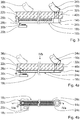
- FIG. 2 shows a not to scale sectional view through the home appliance control device along a line II-II in FIG. 1
- the shielding unit 22a comprises a dielectric element 28a which is provided to electrically shield a conducting element 18a.
- the dielectric element 28a is in an environment of the guide element 18a between the control panel 12a and the Guiding element 18a arranged.
- the sensor plate 14 and the guide element 18a are integrally applied as an electrically conductive coating 24a in a screen printing process on an underside of the control panel 12a opposite the upper side.
- the dielectric member 28a is a screen-printed ceramic coating of the control panel 12a having a larger dielectric constant than the control panel 12a.
- the dielectric element 28a is first coated on the underside of the control panel 12a. Subsequently, the electrically conductive coating 24a is applied, which forms the sensor plate 14a and the guide element 18a.
- the dielectric element 28a attenuates an electric field emitted by the guide element 18a in the vicinity of the guide element 18a in the direction of the control panel 12a.
- a finger 36a in a region above the guide element 18a
- only a slight influence of the electric field which is bypassed by the touch sensor unit 20a, occurs.
- touching the control panel 12a in the area of the touch control surface 10a greatly influences the electric field 40a emanating from the sensor panel 14a.
- the touch sensor unit 20a registers an operation of the touch operation surface 10a.
- FIGS. 4a and 4b show exemplary embodiments of a domestic appliance operating device according to the invention.
- the following descriptions and the drawings are essentially limited to the differences between the exemplary embodiments, wherein with respect to like-named components, in particular with regard to components with the same reference numerals, in principle also to the drawings and / or the descriptions of the other embodiments, in particular Figures 1 and 2 , can be referenced.
- the letters "a", "b” and “c” are attached to the reference numerals of the embodiments.
- FIG. 3 shows a not-to-scale sectional view through a household appliance control device with a preferred embodiment of a shielding unit 22b.
- the shielding unit 22b comprises an electrically conductive element 26b, which is connected to a reference voltage terminal and which is intended to shield an electric field of the conducting element 18b.
- the reference voltage terminal is a protective earth terminal of the glass ceramic cooking panel.
- the electrically conductive element 26b is arranged between a control panel 12b and a guide element 18b.
- a dielectric element 28b is arranged between the guide element 18b and the electrically conductive element 26b.
- a sensor plate 14b and the guide element 18b are integrally applied as an electrically conductive coating 24b in a screen printing process on a lower side of the control panel 12b.
- the electrically conductive element 26b is a coating identical to the conductive coating 24b.
- the dielectric member 28b is a ceramic coating applied by a screen printing method.
- the electrically conductive element 26b is first applied in a screen printing process on the underside of the control panel 12b. Subsequently, the dielectric element 28b is applied in a screen printing process via the electrically conductive element 26b. Finally, the conductive coating 24b constituting the sensor plate 14b and the guide member 18b is applied to the operation panel 12b and the dielectric member 28b.
- the electrically conductive element 26b shields an electric field emanating from the guide element 18b in the vicinity of the guide element 18b in the direction of the control panel 12b.
- the coating forming the electrically conductive element 26b may also have recesses and, in particular, be embodied in a lattice structure. This material can be saved.
- FIG. 4a shows a not-to-scale sectional view through a household appliance control device with a particularly preferred embodiment of a shielding unit 22c.
- the shielding unit 22c includes an electrically conductive member 26c connected to a reference voltage terminal, which is provided to shield an electric field of a conductive member 18c.
- the reference voltage terminal is a protective earth terminal of the glass ceramic cooking panel.
- the electrically conductive element 26c is arranged in a direction parallel to a control panel 12c direction laterally adjacent to the guide element 18c.
- FIG. 4b shows this situation in a not to scale top view of the home appliance device, the control panel 12c is not shown for clarity.
- the electrically conductive element 26c surrounds the guide element 18c almost completely except for a recess in an environment of the sensor plate 14c.
- the electrically conductive element 26c and the guide element 18c are electrically insulated from each other by the smallest possible spacing.
- a sensor plate 14c and the guide element 18c are integrally applied as an electrically conductive coating 24c in a screen printing process on a lower side of the control panel 12c.
- the electrically conductive element 26c is a coating identical to the conductive coating 24c. In a production of the household appliance operating device, the conductive coating 24c and the electrically conductive element 26c are applied in one working step. An application of the conductive coating 24c and the electrically conductive element 26c takes place in a screen printing process.
- the conductive coating 24c and the electrically conductive element 26c by means of a sputtering method.
- the electrically conductive element 26c shields an electric field emanating from the guide element 18c in the vicinity of the guide element 18c in the direction of the control panel 12c.
- a touch sensor unit 20c Upon contact of the control panel 12c with a finger 36c in a region above the guide element 18c, only occurs to a small influence of the electric field, which is passed by a touch sensor unit 20c. On the other hand, touching the control panel 12c in the area of a touch control surface 10c greatly influences an electric field 40c emanating from the sensor panel 14c. The touch sensor unit 20c registers an operation of the touch operation surface 10c.
Description
- Die Erfindung geht aus von einer Hausgerätebedienvorrichtung nach dem Oberbegriff des Anspruchs 1.
- Die Druckschrift
DE 10 2008 041 517 A1 offenbart eine Hausgerätebedienvorrichtung mit einer Touch-Bedienoberfläche an einer Oberseite einer elektrisch isolierenden Bedienblende. Auf einer Unterseite der Bedienblende ist in einem Siebdruckverfahren eine leitfähige Beschichtung aufgebracht, die eine unterhalb der Touch-Bedienoberfläche angeordnete Sensorplatte und ein Leitelement bildet, welches die Sensorplatte elektrisch leitend mit einer Touch-Sensoreinheit kontaktiert. - Aus der Druckschrift
EP 2 110 834 A1 ist eine Bedienvorrichtung bekannt, welche insbesondere für ein Fahrzeug vorgesehen ist, mit einer eine Touch-Bedienoberfläche umfassenden Bedienblende, einer unterhalb der Touch-Bedienoberfläche angeordneten Sensorplatte und einem Leitelement, welches mit der Sensorplatte verbunden ist. Ferner offenbart die Druckschrift ein elektrisch leitendes Element, welches mit einer Referenzspannung verbunden ist. - Die Druckschrift
EP 2 169 315 A2 offenbart eine Bedienblende für ein Haushaltsgerät mit einem Blendenkörper, wobei ein Sensorelement auf der Rückseite des Blendenkörpers angeordnet ist. Das Sensorelement bildet zusammen mit dem Blendenkörper ein kapazitives Sensorfeld, wobei das Sensorelement mit einer Konvertierungselektronik elektrisch leitend verbunden ist und von einem Abschirmelement umgeben ist. - Die Druckschrift
EP 1 953 915 A2 offenbart eine Hausgerätebedienvorrichtung nach dem Oberbegriff des Anspruchs 1 und stellt den nächstliegenden Stand der Technik dar. Die Aufgabe der Erfindung besteht insbesondere darin, eine gattungsgemäße Hausgerätebedienvorrichtung mit verbesserten Eigenschaften hinsichtlich eines flexiblen Designs bereitzustellen. Die Aufgabe wird erfindungsgemäß durch die Merkmale des Patentanspruchs 1 gelöst, während vorteilhafte Ausgestaltungen und Weiterbildungen der Erfindung den Unteransprüchen entnommen werden können. - Die Erfindung geht aus von einer Hausgerätebedienvorrichtung, insbesondere einer Kochfeldbedienvorrichtung, mit einer eine Touch-Bedienoberfläche umfassenden Bedienblende, einer unterhalb der Touch-Bedienoberfläche angeordneten Sensorplatte und einer Signalübertragungseinheit, die die Sensorplatte mittels eines Leitelements mit einer Touch-Sensoreinheit elektrisch leitend verbindet.
- Es wird vorgeschlagen, dass die Signalübertragungseinheit zumindest eine Abschirmeinheit aufweist. Unter "vorgesehen" soll insbesondere speziell programmiert, ausgelegt und/oder ausgestattet verstanden werden. Unter einer "Bedienblende" soll insbesondere eine in einem montierten Zustand durch einen Bediener anfassbare Wand eines Hausgeräts, insbesondere eine Kochfeldplatte eines Kochfelds, verstanden werden, die einen Teilbereich aufweist, der eine Touch-Bedienoberfläche bildet. Vorzugsweise ist die Bedienblende zumindest teilweise aus einem elektrisch isolierenden Material, insbesondere einer Glaskeramik, gebildet. Besonders vorteilhaft ist der die Touch-Bedienoberfläche bildende Teilbereich der Bedienblende aus einem elektrisch isolierenden Material, insbesondere einer Glaskeramik gebildet. Unter "elektrisch isolierend" soll insbesondere mit einem spezifischen elektrischen Widerstand von mindestens 108 Ωm, insbesondere wenigstens 1010 Ωm und vorteilhaft zumindest 1012 Ωm bei 20°C verstanden werden. Unter einer "Touch-Bedienoberfläche" soll insbesondere ein Oberflächenbereich der Bedienblende verstanden werden, der ein Bedienelement bildet, welches durch Berühren, insbesondere auslenkungsfrei, betätigbar ist. Unter einem "Betätigen" eines Bedienelements soll insbesondere ein Durchführen eines Bedienvorgangs oder eines Teils eines Bedienvorgangs mit Hilfe des Bedienelements verstanden werden. Vorzugsweise ist der die Touch-Bedienoberfläche bildende Teilbereich der Bedienblende auf einer einem Bediener zugewandten ersten Seite der Bedienblende mit Markierungen versehen. Unter einer "Sensorplatte" soll insbesondere eine elektrisch leitende Platte verstanden werden, die eine Elektrode bildet und elektrisch leitend mit einer Touch-Sensoreinheit verbunden ist. Vorzugsweise weist die Sensorplatte zumindest eine Ausnehmung auf. Unter "elektrisch leitend" soll insbesondere mit einem spezifischen elektrischen Widerstand von höchstens 10-4 Ωm, insbesondere maximal 10-5 Ωm und vorteilhaft höchstens 10-6 Ωm bei 20°C verstanden werden. Darunter, dass die Sensorplatte "unterhalb" der Touch-Bedienoberfläche angeordnet ist, soll insbesondere verstanden werden, dass die Sensorplatte an einer der ersten Seite gegenüberliegenden zweiten Seite der Bedienblende angeordnet, insbesondere unmittelbar angeordnet und vorzugsweise befestigt ist. Insbesondere umschließt bei einer Blickrichtung senkrecht zur Touch-Bedienoberfläche eine Außenkonturlinie der Sensorplatte eine Außenkonturlinie der Touch-Bedienoberfläche vollständig. Vorzugsweise fallen bei einer Blickrichtung senkrecht zur Touch-Bedienoberfläche die Außenkonturlinien von Sensorplatte und Touch-Bedienoberfläche zusammen. Unter einer "Signalübertragungseinheit" soll insbesondere eine Einheit verstanden werden, die zumindest ein Leitelement umfasst, welches die Sensorplatte mit der Touch-Sensoreinheit elektrisch leitend verbindet. Unter einer "Touch-Sensoreinheit" soll insbesondere eine elektronische Einheit verstanden werden, die elektrisch leitend mit einer Sensorplatte verbunden ist und die dazu vorgesehen ist, die Sensorplatte elektrisch aufzuladen und eine Änderung eines von der Sensorplatte ausgehenden elektrischen Felds zu detektieren. Vorzugsweise ist die Touch-Sensoreinheit mit einer Steuer- und/oder Regeleinheit des Hausgeräts verbunden und ist zu einer Eingabe von zumindest einem Betriebsparameter des Hausgeräts vorgesehen. Darunter, dass die Sensorplatte mittels des Leitelements mit einer Touch-Sensoreinheit "elektrisch leitend" verbunden wird, soll insbesondere verstanden werden, dass eine elektrisch leitende Verbindung zwischen der Sensorplatte und der Touch-Sensoreinheit existiert, welche das Leitelement umfasst. Unter einer "Abschirmeinheit" der Signalübertragungseinheit soll insbesondere eine von einer Elektronikplatine und/oder der Bedienblende differierende Einheit verstanden werden, welche dazu vorgesehen ist, zumindest eine wesentliche Beeinflussung eines von dem Leitelement ausgehenden elektrischen Felds bei einer Kontaktierung eines Bereichs der Bedienblende oberhalb des Leitelements zu unterbinden. Unter einer "wesentlichen Beeinflussung" des von dem Leitelement ausgehenden elektrischen Felds soll insbesondere eine Änderung des elektrischen Felds verstanden werden, die von der Touch-Sensoreinheit als ein auslösendes Ereignis erfasst wird. Die Kontaktierung des Bereichs der Bedienblende oberhalb des Leitelements kann dabei von einem Bediener und/oder einem Kochgeschirr und/oder jedem beliebigen anderen Objekt erfolgen.
- Durch eine solche Ausgestaltung kann bei einer zuverlässigen Funktion der Touch-Bedienoberfläche eine Beabstandung der Sensorplatte von der Touch-Sensoreinheit ermöglicht werden. Insbesondere kann hierdurch eine Platzierung der Touch-Bedienelemente in besonders geeigneten Teilbereichen der Bedienblende erfolgen. Ferner können verschiedene Bedienblenden mit einer unterschiedlichen Anordnung von Touch-Bedienoberflächen bereitgestellt werden, bei denen eine Anordnung der Touch-Sensoreinheiten identisch ist und die sich lediglich durch eine Anordnung der Sensorplatten und durch eine Ausgestaltung der Signalübertragungseinheit unterscheiden. Des Weiteren kann eine kommerziell verfügbare Touch-Sensoreinheit verwendet werden. Dies ermöglicht einerseits ein vorteilhaft flexibleres Design und andererseits eine Reduzierung eines Montageaufwands und eine Kostenreduktion. Insbesondere wenn die Signalübertragungseinheit Beschichtungen auf der Bedienblende aufweist, kann besonders einfach und kostengünstig eine Variation für verschiedene Ausgestaltungen der Bedienblende vorgenommen werden. Des Weiteren können, insbesondere bei Gargeräten oder Kochfeldern, die Touch-Bedienoberfläche und die zugehörige Signalfläche in einem Flächenbereich der Bedienblende vorgesehen sein, welcher eine Temperatur oberhalb einer für einen zuverlässigen Betrieb der Signaleinheit zulässigen Temperaturobergrenze aufweist. Hierdurch kann eine vorteilhafte Nähe einer Kochzone eines Kochfelds und einer Touch-Bedienoberfläche erreicht werden.
- Vorteilhaft sind die Sensorplatte und die Touch-Sensoreinheit wesentlich beabstandet. Darunter, dass die Sensorplatte und die Touch-Sensoreinheit "wesentlich beabstandet" sind, soll insbesondere verstanden werden, dass ein Abstand zwischen der Sensorplatte und der Touch-Sensoreinheit in einer zu der Bedienblende parallelen Ebene zumindest 2-mal, insbesondere 5-mal, vorteilhaft 10-mal und besonders vorteilhaft 20-mal so groß ist wie eine maximale Erstreckungslänge der Sensorplatte in der Ebene. Unter einem "Abstand zwischen der Sensorplatte und der Touch-Sensoreinheit in einer zu der Bedienblende parallelen Ebene" soll bei einer Projektion der Sensorplatte und der Touch-Sensoreinheit auf die Bedienblende insbesondere eine kleinste Distanz zwischen der Konturlinie der Sensorplatte und einer Konturlinie der Touch-Sensoreinheit verstanden werden. Unter einer "maximalen Erstreckungslänge der Sensorplatte in der Ebene" soll bei einer Projektion der Sensorplatte auf die Bedienblende insbesondere eine maximale Distanz zwischen zwei Randpunkten der Konturlinie der Sensorplatte verstanden werden. Hierdurch kann eine vorteilhafte Steigerung eines Bedienkomforts ermöglicht werden, da die Touch-Bedienoberfläche in einem Teilbereich der Bedienblende angeordnet werden kann, der für die Touch-Sensoreinheit, insbesondere durch eine erhöhte Temperatur, ausgeschlossen ist. Des Weiteren kann eine Kostenreduktion erzielt werden, da verschiedene Ausgestaltungen einer Bedienblende mit einer Touch-Bedienoberfläche erreicht werden können, die sich lediglich durch eine Position einer Sensorplatte und durch eine Ausführung einer Signalübertragungseinheit unterscheiden.
- Ferner wird vorgeschlagen, dass die Sensorplatte und das Leitelement einstückig als eine leitfähige Beschichtung ausgeführt sind. Darunter, dass die Sensorplatte und das Leitelement "einstückig als eine leitfähige Beschichtung" ausgeführt sind, soll insbesondere verstanden werden, dass die Sensorplatte und das Leitelement eine zusammenhängende, elektrisch leitende Beschichtung auf einem Substrat bilden. Vorzugsweise wurden die Sensorplatte und das Leitelement in einem einzigen Beschichtungsprozess aufgebracht. Vorzugsweise ist die leitfähige Beschichtung unmittelbar an der zweiten Seite der Bedienblende und/oder an einer weiteren Beschichtung an der zweiten Seite der Bedienblende aufgebracht.
- Durch diese Ausgestaltung kann eine zuverlässige Kontaktierung der Sensorplatte mit der Bedienblende erzielt werden. Ferner kann besonders Platz sparend eine besonders zuverlässige elektrische Kontaktierung zwischen der Sensorplatte und dem Leitelement bereitgestellt werden. Vorzugsweise beträgt eine Dicke der leitfähigen Beschichtung mindestens 30 µm, insbesondere mindestens 50 µm, vorteilhaft mindestens 70 µm und besonders vorteilhaft mindestens 90 µm. Hierdurch kann eine ausreichend hohe elektrische Leitfähigkeit der Beschichtung erreicht werden. Vorzugsweise beträgt die Dicke der leitfähigen Beschichtung höchstens 200 µm, insbesondere maximal 170 µm, vorteilhaft höchstens 140 µm und besonders vorteilhaft maximal 110 µm. Hierdurch kann Material eingespart und ein Zeitbedarf für eine Herstellung reduziert werden. Vorzugsweise ist die leitfähige Beschichtung durch ein Kathodenzerstäubungsverfahren auf das Substrat aufgebracht und besteht insbesondere aus reinen Metallen. Hierdurch kann eine Beschichtung der Bedienblende bei einer niedrigen Temperatur erreicht werden, was einer möglichen Beschädigung und/oder Beeinträchtigung einer Stabilität der Bedienblende entgegenwirkt. Vorzugsweise ist die leitfähige Beschichtung aus einer pastenartigen Suspension hergestellt, die zumindest fein verteilte Metallteilchen, insbesondere in Form von Pulver und/oder Flocken und/oder Folie und/oder Streifen, einen anorganischer Träger zur Bindung der Beschichtung an das Substrat, insbesondere eine Glasfritte, und ein Bindemittel, insbesondere Diethylenglykol und/oder ein Monobutylether des Diethylenglykols, aufweist und die vorzugsweise durch ein Siebdruckverfahren auf das Substrat aufgebracht ist. Die Metallteilchen machen zumindest 5%, insbesondere wenigstens 30%, vorzugsweise mindestens 50% und besonders vorteilhaft zumindest 80% und vorteilhaft höchstens 95% einer Gesamtmasse der Suspension aus und umfassen vorzugsweise Edelmetalle, insbesondere Gold und/oder Silber und/oder Platin und/oder Palladium, und/oder Legierungen aus Edelmetallen und/oder Nickel und/oder Kupfer und/oder Aluminium und/oder Cobalt und/oder Eisen und/oder Wismut. Vorzugsweise wird die Suspension nach einem Aufbringen auf das Substrat bei einer Temperatur zwischen 600°C und 700°C gesintert, wobei das Bindemittel verdampft und/oder verbrannt wird. Hierdurch können Herstellungskosten reduziert werden.
- Die Abschirmeinheit umfasst zumindest ein mit einem Referenzspannungsanschluss verbundenes elektrisch leitendes Element, welches dazu vorgesehen ist, ein elektrisches Feld des Leitelements abzuschirmen. Insbesondere ist das elektrisch leitfähige Element eine elektrisch leitfähige Beschichtung, vorzugsweise auf der zweiten Seite der Bedienblende. Darunter, dass das elektrisch leitende Element dazu vorgesehen ist, das elektrische Feld des Leitelements abzuschirmen, soll insbesondere verstanden werden, dass das elektrisch leitende Element dazu vorgesehen ist, zumindest eine wesentliche Beeinflussung eines von dem Leitelement ausgehenden elektrischen Felds bei einer Kontaktierung eines Bereichs der Bedienblende oberhalb des Leitelements zu unterbinden. Unter einem "Referenzspannungsanschluss" soll insbesondere ein elektrischer Anschluss mit einem konstanten elektrischen Potential verstanden werden. Durch eine solche Ausgestaltung kann eine wesentliche Beeinflussung des vom Leitelement ausgehenden elektrischen Felds bei einer Kontaktierung eines Flächenbereichs der Bedienblende oberhalb des Leitelements unterbunden werden, da elektrische Ladungen vom elektrisch leitenden Element abgeführt werden können.
- In einer besonders bevorzugten Ausgestaltung wird vorgeschlagen, dass der Referenzspannungsanschluss ein Erdungsanschluss ist. Vorzugsweise ist der Erdungsanschluss ein Schutzerdungsanschluss und besonders vorteilhaft ein Funktionserdungsanschluss. Hierdurch kann eine besonders einfache und vorteilhafte Abschirmung des Leitelements ermöglicht werden.
- Das elektrisch leitende Element ist in einer zur Touch-Bediehoberfläche parallelen Richtung zumindest teilweise seitlich neben dem Leitelement angeordnet. Darunter, dass "das elektrisch leitende Element in einer zur Touch-Bedienoberfläche parallelen Richtung zumindest teilweise seitlich neben dem Leitelement angeordnet ist", soll insbesondere verstanden werden, dass zumindest eine, zur Touch-Bedienoberfläche parallele Ebene das Leitelement und das elektrisch leitende Element schneidet. Hierdurch kann eine besonders einfache Abschirmung des Leitelements erreicht werden, da auf ein elektrisch isolierendes Element zwischen dem Leitelement und dem elektrisch leitenden Element verzichtet werden kann.
- In einer weiteren Ausgestaltung der Erfindung wird vorgeschlagen, dass das elektrisch leitende Element zumindest teilweise zwischen dem Leitelement und der Bedienblende angeordnet ist. Darunter, dass "das elektrisch leitende Element zumindest teilweise zwischen dem Leitelement und der Bedienblende angeordnet ist", soll insbesondere verstanden werden, dass zumindest eine zur Touch-Bedienoberfläche senkrechte Gerade das Leitelement und das elektrisch leitende Element schneidet. Hierdurch kann eine besonders effektive Abschirmung des Leitelements erreicht werden. Vorzugsweise weist das Leitelement Aussparungen auf. Hierdurch kann Material eingespart werden und es können Kosten reduziert werden.
- Ferner wird vorgeschlagen, dass die Abschirmeinheit zumindest ein dielektrisches Element umfasst, welches dazu vorgesehen ist, das Leitelement elektrisch abzuschirmen. Unter einem "dielektrischen Element" soll insbesondere ein elektrisch isolierendes Element verstanden werden, welches aufgrund einer dielektrischen Polarisation zu einer Schwächung eines elektrischen Felds führt. Darunter, dass das dielektrische Element dazu vorgesehen ist, "das Leitelement elektrisch abzuschirmen", soll insbesondere verstanden werden, dass das dielektrische Element das Leitelement gegenüber anderen Bauteilen, insbesondere dem elektrisch leitende Element, elektrisch isoliert und/oder eine wesentliche Beeinflussung eines von dem Leitelement ausgehenden elektrischen Felds bei einer Kontaktierung eines Bereichs der Bedienblende oberhalb des Leitelements unterbindet. Vorteilhaft weist das dielektrische Element einen spezifischen elektrischen Widerstand auf, der in einer gleichen Größenordnung wie ein spezifischer elektrischer Widerstand der Bedienblende liegt. Ferner weist das dielektrische Element vorzugsweise eine Dielektrizitätszahl auf, die größer ist als eine Dielektrizitätszahl der Bedienblende. Hierdurch können weitere vorteilhafte Ausgestaltungen der Hausgerätebedienvorrichtung ermöglicht werden. Vorzugsweise ist das dielektrische Element als eine elektrisch isolierende Beschichtung, insbesondere eine keramische Beschichtung und besonders vorteilhaft eine Emaille, ausgebildet. Hierdurch können Herstellungskosten reduziert werden. Vorzugsweise beträgt eine Dicke der isolierenden Beschichtung mindestens 30 µm, insbesondere mindestens 50 µm, vorteilhaft mindestens 70 µm und besonders vorteilhaft mindestens 100 µm. Hierdurch kann eine ausreichend hohe Abschirmung erreicht werden. Vorzugsweise beträgt die Dicke der isolierenden Beschichtung höchstens 200 µm, insbesondere maximal 170 µm, vorteilhaft höchstens 140 µm und besonders vorteilhaft maximal 110 µm. Hierdurch kann Material eingespart und ein Zeitbedarf für eine Herstellung reduziert werden. Vorzugsweise wird das dielektrische Element zwischen dem Leitelement und dem mit dem Referenzspannungsanschluss verbundenen elektrisch leitenden Element eingebracht. Hierdurch kann eine elektrische Isolierung zwischen dem Leitelement und dem elektrisch leitenden Element bereitgestellt werden.
- In einer weiteren Ausgestaltung der Erfindung wird vorgeschlagen, dass das dielektrische Element zumindest teilweise zwischen dem Leitelement und der Bedienblende angeordnet ist. Darunter, dass "das dielektrische Element zumindest teilweise zwischen dem Leitelement und der Bedienblende angeordnet ist", soll insbesondere verstanden werden, dass zumindest eine zur Touch-Bedienoberfläche senkrechte Gerade das Leitelement und das dielektrische Element schneidet. Vorzugsweise liegt das dielektrische Element unmittelbar am Leitelement und/oder an der Bedienblende an. Hierdurch kann bei einer Kontaktierung der Bedienblende in einem Flächenbereich oberhalb des Leitmittels eine Abschwächung eines Einflusses auf das elektrische Feld erreicht werden.
- In einer bevorzugten Ausgestaltung wird vorgeschlagen, dass die Signalübertragungseinheit ein Federelement umfasst, das dazu vorgesehen ist, das Leitelement mit der Touch-Sensoreinheit elektrisch leitend zu verbinden. Unter einem "Federelement" soll insbesondere ein elastisches Element verstanden werden, welches in einem montierten Zustand, vorzugsweise mit einer Vorspannung, zwischen dem Leitelement und der Touch-Sensoreinheit angeordnet ist. Vorzugsweise besteht das Federelement aus einem elektrisch leitenden Material. Vorzugsweise ist das Federelement ein Leitgummi, eine metallische Schraubenfeder oder eine metallische Blattfeder. Hierdurch kann eine zuverlässige elektrische Kontaktierung des Leitelements mit der Touch-Sensoreinheit erreicht werden. Die erfindungsgemäße Hausgerätebedienvorrichtung eignet sich für sämtliche, einem Fachmann als sinnvoll erscheinende Hausgeräte, wie insbesondere Gargeräte, Kühlgeräte, Spüler usw., und besonders vorteilhaft Kochfelder.
- Weitere Vorteile ergeben sich aus den folgenden Zeichnungsbeschreibungen. In den Zeichnungen 4a und 4b sind Ausführungsbeispiele der Erfindung dargestellt. Die Zeichnungen, die Beschreibungen und die Ansprüche enthalten zahlreiche Merkmale in Kombination. Der Fachmann wird die Merkmale zweckmäßigerweise auch einzeln betrachten und zu sinnvollen weiteren Kombinationen zusammenfassen.
-
- Fig. 1
- ein Glaskeramikkochfeld mit einer Hausgerätebedienvorrichtung in einer Draufsicht,
- Fig. 2
- die Hausgerätebedienvorrichtung aus
Fig. 1 mit einer Abschirmeinheit, die ein dielektrisches Element umfasst, in einer nicht maßstabsgetreuen Schnittdarstellung entlang einer Linie II-II inFig. 1 , - Fig. 3
- eine Hausgerätebedienvorrichtung in einer nicht maßstabsgetreuen Schnittdarstellung mit einer Abschirmeinheit, welche ein dielektrisches Element und ein elektrisch leitendes Element umfasst,
- Fig. 4a
- eine weitere Hausgerätebedienvorrichtung in einer nicht maßstabsgetreuen Schnittdarstellung mit einer Abschirmeinheit, welche ein elektrisch leitendes Element umfasst,
- Fig. 4b
- die Hausgerätebedienvorrichtung aus
Fig. 4a in einer nicht maßstabsgetreuen Draufsicht bei entfernter Kochfeldplatte. -
Figur 1 zeigt in einer Draufsicht ein Glaskeramikkochfeld mit einer Hausgerätebedienvorrichtung. Das Glaskeramikkochfeld umfasst eine Kochfeldplatte 32a aus Glaskeramik, die eine Bedienblende 12a der Hausgerätevorrichtung bildet. Die Bedienblende 12a weist einen Teilbereich auf, der eine Touch-Bedienoberfläche 10a darstellt und der von einem Bediener anfassbar ist. Die Touch-Bedienoberfläche 10a ist in bekannter Weise durch eine keramische Beschichtung auf einer dem Bediener in einem betriebsbereiten Zustand des Glaskeramikkochfelds zugewandten Oberseite der Bedienblende 12a markiert. Die Touch-Bedienoberfläche 10a ist dazu vorgesehen, durch eine Berührung mit einem Finger 34a betätigt zu werden. Im vorliegenden Fall ist die Touch-Bedienoberfläche 10a dazu vorgesehen, eine neben der Touch-Bedienoberfläche 10a angeordnete Kochzone 38a der Kochfeldplatte 32a zu- oder abzuschalten und zu einer Einstellung einer Heizleistung anzuwählen. Hierzu verfügt die Hausgerätebedienvorrichtung über eine unterhalb der Bedienblende 12a angeordnete Sensorplatte 14a, die bei einer zur Touch-Bedienoberfläche 10a senkrechten Blickrichtung eine identischen Außenkontur wie die Touch-Bedienoberfläche 10a aufweist. Die Sensorplatte 14a ist in einem betriebsbereiten Zustand des Glaskeramikkochfelds exakt unter der Touch-Bedienoberfläche 10a angeordnet. Die Sensorplatte 14a gleicht einer flachen Kreisringscheibe (vgl. Sensorplatte 14c inFigur 4b ). Die Sensorplatte 14a ist mittels eines Leitelements 18a einer Signalübertragungseinheit 16a mit einer von der Sensorplatte 14a wesentlich beabstandeten Touch-Sensoreinheit 20a elektrisch leitend verbunden. Die Touch-Sensoreinheit 20a ist dazu vorgesehen, eine Veränderung eines von der Sensorplatte 14a ausgehenden elektrischen Felds 40a zu registrieren (vgl.Figur 2 ). Um eine zuverlässige elektrisch leitende Kontaktierung der Touch-Sensoreinheit 20a mit dem Leitelement 18a der Signalübertragungseinheit 16a sicherzustellen, umfasst die Signalübertragungseinheit 16a ein elastisches Federelement 30a, welches mit einer Vorspannung zwischen dem Leitelement 18a und einer Kontaktstelle der Touch-Sensoreinheit 20a angeordnet ist. Das Federelement 30a ist aus einem Leitgummi gebildet. Alternativ kann das Federelement 30a auch aus einer Schraubenfeder und/oder Blattfeder und/oder jedem beliebigen, einem Fachmann als sinnvoll erscheinenden federnden Element gebildet sein. Um sicherzustellen, dass nur eine Berührung durch einen Finger 34a im Bereich der Touch-Bedienoberfläche 10a als eine Betätigung der Touch-Bedienoberfläche 10a erkannt wird, umfasst die Signalübertragungseinheit 16a eine Abschirmeinheit 22a. Die Abschirmeinheit 22a verhindert, dass eine Berührung der Bedienblende 12a mit einem Finger 36a in einem Bereich oberhalb des Leitelements 18a zu einer wesentlichen Beeinflussung eines vom Leitelement 18a ausgehenden elektrischen Felds führt, welche von der Touch-Sensoreinheit 20a als eine Betätigung der Touch-Bedienoberfläche 10a erkannt wird. -
Figur 2 zeigt eine nicht maßstabsgetreue Schnittdarstellung durch die Hausgerätebedienvorrichtung entlang einer Linie II-II inFigur 1 . Die Abschirmeinheit 22a umfasst ein dielektrisches Element 28a, welches dazu vorgesehen ist, ein Leitelement 18a elektrisch abzuschirmen. Hierzu ist das dielektrische Element 28a in einer Umgebung des Leitelements 18a zwischen der Bedienblende 12a und dem Leitelement 18a angeordnet. Die Sensorplatte 14 und das Leitelement 18a sind einstückig als eine elektrisch leitfähige Beschichtung 24a in einem Siebdruckverfahren auf einer der Oberseite gegenüberliegenden Unterseite der Bedienblende 12a aufgebracht. Das dielektrische Element 28a ist eine in einem Siebdruckverfahren aufgebrachte keramische Beschichtung der Bedienblende 12a mit einer größeren Dielektrizitätszahl als die Bedienblende 12a. Bei einer Herstellung der Hausgerätebedienvorrichtung wird zuerst das dielektrische Element 28a auf die Unterseite der Bedienblende 12a beschichtet. Daraufhin wird die elektrisch leitfähige Beschichtung 24a aufgebracht, die die Sensorplatte 14a und das Leitelement 18a bildet. Das dielektrische Element 28a schwächt ein vom Leitelement 18a ausgehendes elektrisches Feld in der Umgebung des Leitelements 18a in Richtung der Bedienblende 12a ab. Bei einer Berührung der Bedienblende 12a mit einem Finger 36a in einem Bereich oberhalb des Leitelements 18a kommt es nur zu einer geringen Beeinflussung des elektrischen Felds, die von der Touch-Sensoreinheit 20a übergangen wird. Bei einer Berührung der Bedienblende 12a im Bereich der Touch-Bedienoberfläche 10a kommt es hingegen zu einer starken Beeinflussung des von der Sensorplatte 14a ausgehenden elektrischen Felds 40a. Die Touch-Sensoreinheit 20a registriert eine Betätigung der Touch-Bedienoberfläche 10a. - Die
Figuren 4a und 4b zeigen Ausführungsbeispiele einer erfindungsgemäßen Hausgerätebedienvorrichtung. Die nachfolgenden Beschreibungen und die Zeichnungen beschränken sich im Wesentlichen auf die Unterschiede zwischen den Ausführungsbeispielen, wobei bezüglich gleich bezeichneter Bauteile, insbesondere in Bezug auf Bauteile mit gleichen Bezugszeichen, grundsätzlich auch auf die Zeichnungen und/oder die Beschreibungen der anderen Ausführungsbeispiele, insbesondere derFiguren 1 und 2 , verwiesen werden kann. Zur Unterscheidung der Ausführungsbeispiele sind die Buchstaben "a", "b" und "c" den Bezugszeichen der Ausführungsbeispiele angehängt.Figur 3 zeigt eine nicht maßstabsgetreue Schnittdarstellung durch eine Hausgerätebedienvorrichtung mit einer bevorzugten Ausgestaltung einer Abschirmeinheit 22b. Die Abschirmeinheit 22b umfasst ein mit einem Referenzspannungsanschluss verbundenes elektrisch leitendes Element 26b, welches dazu vorgesehen ist, ein elektrisches Feld des Leitelements 18b abzuschirmen. Der Referenzspannungsanschluss ist ein Schutzerdungsanschluss des Glaskeramikkochfelds. Das elektrisch leitende Element 26b ist zwischen einer Bedienblende 12b und einem Leitelement 18b angeordnet. Zur elektrischen Isolierung ist zwischen dem Leitelement 18b und dem elektrisch leitenden Element 26b ein dielektrisches Element 28b angeordnet. Eine Sensorplatte 14b und das Leitelement 18b sind einstückig als eine elektrisch leitfähige Beschichtung 24b in einem Siebdruckverfahren auf einer Unterseite der Bedienblende 12b aufgebracht. Das elektrisch leitende Element 26b ist eine zu der leitfähigen Beschichtung 24b identische Beschichtung. Das dielektrische Element 28b ist eine in einem Siebdruckverfahren aufgebrachte keramische Beschichtung. Bei einer Herstellung der Hausgerätebedienvorrichtung wird zuerst das elektrisch leitende Element 26b in einem Siebdruckverfahren an der Unterseite der Bedienblende 12b aufgebracht. Anschließend wird das dielektrische Element 28b in einem Siebdruckverfahren über das elektrisch leitende Element 26b aufgebracht. Schließlich wird die leitfähige Beschichtung 24b, die die Sensorplatte 14b und das Leitelement 18b bildet, auf die Bedienblende 12b und das dielektrische Element 28b aufgebracht. Das elektrisch leitende Element 26b schirmt ein vom Leitelement 18b ausgehendes elektrisches Feld in der Umgebung des Leitelements 18b in Richtung der Bedienblende 12b ab. Bei einer Berührung der Bedienblende 12b mit einem Finger 36b in einem Bereich oberhalb des Leitelements 18b kommt es nur zu einer geringen Beeinflussung des elektrischen Felds, die von einer Touch-Sensoreinheit 20b übergangen wird. Bei einer Berührung der Bedienblende 12b im Bereich einer Touch-Bedienoberfläche 10b kommt es hingegen zu einer starken Beeinflussung des von der Sensorplatte 14b ausgehenden elektrischen Felds 40b. Die Touch-Sensoreinheit 20b registriert eine Betätigung der Touch-Bedienoberfläche 10b. In einer alternativen Ausgestaltung kann die das elektrisch leitende Element 26b bildende Beschichtung auch Ausnehmungen aufweisen und insbesondere in einer Gitterstruktur ausgeführt sein. Hierdurch kann Material eingespart werden. -
Figur 4a zeigt eine nicht maßstabsgetreue Schnittdarstellung durch eine Hausgerätebedienvorrichtung mit einer besonders bevorzugten Ausgestaltung einer Abschirmeinheit 22c. Die Abschirmeinheit 22c umfasst ein mit einem Referenzspannungsanschluss verbundenes elektrisch leitendes Element 26c, welches dazu vorgesehen ist, ein elektrisches Feld eines Leitelements 18c abzuschirmen. Der Referenzspannungsanschluss ist ein Schutzerdungsanschluss des Glaskeramikkochfelds. Das elektrisch leitende Element 26c ist in einer zu einer Bedienblende 12c parallelen Richtung seitlich neben dem Leitelement 18c angeordnet.Figur 4b zeigt diesen Sachverhalt in einer nicht maßstabsgetreuen Draufsicht auf die Hausgerätevorrichtung, wobei die Bedienblende 12c zu einer besseren Übersicht nicht dargestellt ist. Das elektrisch leitende Element 26c umgreift das Leitelement 18c nahezu vollständig bis auf eine Ausnehmung in einer Umgebung der Sensorplatte 14c. Das elektrisch leitende Element 26c und das Leitelement 18c sind durch eine möglichst kleine Beabstandung voneinander elektrisch isoliert. Eine Sensorplatte 14c und das Leitelement 18c sind einstückig als eine elektrisch leitfähige Beschichtung 24c in einem Siebdruckverfahren auf eine Unterseite der Bedienblende 12c aufgebracht. Das elektrisch leitende Element 26c ist eine zu der leitfähigen Beschichtung 24c identische Beschichtung. Bei einer Herstellung der Hausgerätebedienvorrichtung werden die leitfähige Beschichtung 24c und das elektrisch leitende Element 26c in einem Arbeitsschritt aufgebracht. Ein Aufbringen der leitfähigen Beschichtung 24c und des elektrisch leitenden Elements 26c erfolgt in einem Siebdruckverfahren. Alternativ ist jedoch auch denkbar, die leitfähige Beschichtung 24c und das elektrisch leitende Element 26c durch ein Kathodenzerstäubungsverfahren aufzubringen. Hierbei empfiehlt es sich, die leitfähige Beschichtung 24c und das elektrisch leitende Element 26c als eine zusammenhängende Fläche auf die Unterseite der Bedienblende 12c aufzubringen und anschließend eine räumliche Trennung der leitfähigen Beschichtung 24c und des elektrisch leitenden Elements 26c durch ein Laserablationsverfahren vorzunehmen. Das elektrisch leitende Element 26c schirmt ein vom Leitelement 18c ausgehendes elektrisches Feld in der Umgebung des Leitelements 18c in Richtung der Bedienblende 12c ab. Bei einer Berührung der Bedienblende 12c mit einem Finger 36c in einem Bereich oberhalb des Leitelements 18c kommt es nur zu einer geringen Beeinflussung des elektrischen Felds, die von einer Touch-Sensoreinheit 20c übergangen wird. Bei einer Berührung der Bedienblende 12c im Bereich einer Touch-Bedienoberfläche 10c kommt es hingegen zu einer starken Beeinflussung eines von der Sensorplatte 14c ausgehenden elektrischen Felds 40c. Die Touch-Sensoreinheit 20c registriert eine Betätigung der Touch-Bedienoberfläche 10c. -
10a Touch-Bedienoberfläche 28b dielektrisches Element 10b Touch-Bedienoberfläche 30a Federelement 10c Touch-Bedienoberfläche 30b Federelement 12a Bedienblende 30c Federelement 12b Bedienblende 32a Kochfeldplatte 12c Bedienblende 32b Kochfeldplatte 14a Sensorplatte 32c Kochfeldplatte 14b Sensorplatte 34a Finger 14c Sensorplatte 34b Finger 16a Signalübertragungseinheit 34c Finger 16b Signalübertragungseinheit 36a Finger 16c Signalübertragungseinheit 36b Finger 18a Leitelement 36c Finger 18b Leitelement 38a Kochzone 18c Leitelement 40a elektrisches Feld 20a Touch-Sensoreinheit 40b elektrisches Feld 20b Touch-Sensoreinheit 40c elektrisches Feld 20c Touch-Sensoreinheit 22a Abschirmeinheit 22b Abschirmeinheit 22c Abschirmeinheit 24a leitfähige Beschichtung 24b leitfähige Beschichtung 24c leitfähige Beschichtung 26b elektrisch leitendes Element 26c elektrisch leitendes Element 28a dielektrisches Element
Claims (8)
- Hausgerätebedienvorrichtung, insbesondere Kochfeldbedienvorrichtung, mit einer eine Touch-Bedienoberfläche (10a; 10b; 10c) umfassenden Bedienblende (12a; 12b; 12c), einer unterhalb der Touch-Bedienoberfläche (10a; 10b; 10c) angeordneten Sensorplatte (14a; 14b; 14c) und einer Signalübertragungseinheit (16a; 16b; 16c), die die Sensorplatte (14a; 14b; 14c) mittels eines Leitelements (18a; 18b; 18c) mit einer Touch-Sensoreinheit (20a; 20b; 20c) elektrisch leitend verbindet, wobei die Signalübertragungseinheit (16a; 16b; 16c) zumindest eine Abschirmeinheit (22a; 22b; 22c) aufweist, wobei die Abschirmeinheit (22b; 22c) zumindest ein mit einem Referenzspannungsanschluss verbundenes elektrisch leitendes Element (26b; 26c) umfasst, welches dazu vorgesehen ist, ein elektrisches Feld des Leitelements (18b; 18c) abzuschirmen, wobei das elektrisch leitende Element (26b; 26c) in einer zur Touch-Bedienoberfläche (10b; 10c) parallelen Richtung zumindest teilweise seitlich neben dem Leitelement (18b; 18c) angeordnet ist, dadurch gekennzeichnet, dass das elektrisch leitende Element (26c) das Leitelement (18c) nahezu vollständig bis auf eine Ausnehmung in einer Umgebung der Sensorplatte (14c) umgreift.
- Hausgerätebedienvorrichtung nach Anspruch 1, dadurch gekennzeichnet, dass die Sensorplatte (14a; 14b; 14c) und die Touch-Sensoreinheit (20a; 20b; 20c) wesentlich beabstandet sind.
- Hausgerätebedienvorrichtung nach einem der vorhergehenden Ansprüche, dadurch gekennzeichnet, dass der Referenzspannungsanschluss ein Erdungsanschluss ist.
- Hausgerätebedienvorrichtung nach einem der vorhergehenden Ansprüche, dadurch gekennzeichnet, dass das elektrisch leitende Element (26b; 26c) zumindest teilweise zwischen der Bedienblende (12b; 12c) und dem Leitelement (18b; 18c) angeordnet ist.
- Hausgerätebedienvorrichtung nach einem der vorhergehenden Ansprüche, dadurch gekennzeichnet, dass die Abschirmeinheit (22a; 22b) zumindest ein dielektrisches Element (28a; 28b) umfasst, welches dazu vorgesehen ist, das Leitelement (18a; 18b) elektrisch abzuschirmen.
- Hausgerätebedienvorrichtung nach Anspruch 5, dadurch gekennzeichnet, dass das dielektrische Element (28a; 28b) zumindest teilweise zwischen der Bedienblende (12a; 12b) und dem Leitelement (18a; 18b) angeordnet ist.
- Hausgerätebedienvorrichtung nach einem der vorhergehenden Ansprüche, dadurch gekennzeichnet, dass die Signalübertragungseinheit (16a; 16b; 16c) ein Federelement (30a; 30b; 30c) umfasst, das dazu vorgesehen ist, das Leitelement (18a; 18b; 18c) mit der Touch-Sensoreinheit (20a; 20b; 20c) elektrisch leitend zu verbinden.
- Hausgerät, insbesondere Glaskeramikkochfeld, mit einer Hausgerätebedienvorrichtung nach einem der vorhergehenden Ansprüche.
Applications Claiming Priority (2)
| Application Number | Priority Date | Filing Date | Title |
|---|---|---|---|
| ES201031350 | 2010-09-10 | ||
| PCT/IB2011/053755 WO2012032432A1 (de) | 2010-09-10 | 2011-08-26 | Hausgerätebedienvorrichtung |
Publications (2)
| Publication Number | Publication Date |
|---|---|
| EP2614308A1 EP2614308A1 (de) | 2013-07-17 |
| EP2614308B1 true EP2614308B1 (de) | 2018-04-04 |
Family
ID=44735977
Family Applications (1)
| Application Number | Title | Priority Date | Filing Date |
|---|---|---|---|
| EP11764300.7A Not-in-force EP2614308B1 (de) | 2010-09-10 | 2011-08-26 | Hausgerätebedienvorrichtung |
Country Status (6)
| Country | Link |
|---|---|
| US (1) | US8982080B2 (de) |
| EP (1) | EP2614308B1 (de) |
| KR (1) | KR101791723B1 (de) |
| CN (1) | CN103109135B (de) |
| ES (1) | ES2665508T3 (de) |
| WO (1) | WO2012032432A1 (de) |
Families Citing this family (16)
| Publication number | Priority date | Publication date | Assignee | Title |
|---|---|---|---|---|
| ES2398787B1 (es) * | 2010-12-16 | 2014-02-18 | BSH Electrodomésticos España S.A. | Procedimiento para fabricar una placa de campo de cocción para un campo de cocción |
| ES2432234B1 (es) * | 2012-05-30 | 2014-11-12 | Bsh Electrodomésticos España, S.A. | Dispositivo de mando de aparato doméstico |
| EP2792951B1 (de) * | 2013-04-18 | 2019-11-06 | BSH Hausgeräte GmbH | Kochfeld |
| CN103381301B (zh) * | 2013-07-26 | 2016-02-17 | 浙江工业大学之江学院工业研究院 | 一种儿童玩的厨房燃气灶智能玩具 |
| KR101677334B1 (ko) | 2014-10-24 | 2016-11-17 | 엘지전자 주식회사 | 냉장고 도어 |
| WO2016072802A1 (en) | 2014-11-07 | 2016-05-12 | Lg Electronics Inc. | Metal touch sensing apparatus, and home appliance having metal touch sensing apparatus and method for controlling the same |
| CN105588400B (zh) | 2014-11-07 | 2018-04-13 | Lg电子株式会社 | 冰箱及冰箱控制方法 |
| KR101659180B1 (ko) | 2014-12-22 | 2016-09-22 | 엘지전자 주식회사 | 터치 센서 어셈블리 및 터치 센서 어셈블리가 구비된 냉장고 도어 |
| KR101659181B1 (ko) | 2014-12-22 | 2016-09-30 | 엘지전자 주식회사 | 터치 센서 어셈블리 및 터치 센서 어셈블리가 구비된 냉장고 도어 |
| KR101668922B1 (ko) | 2014-12-24 | 2016-10-24 | 엘지전자 주식회사 | 디스플레이 어셈블리가 구비된 가전제품 및 그 제조 방법 |
| KR101668921B1 (ko) | 2014-12-24 | 2016-10-24 | 엘지전자 주식회사 | 터치 센서 어셈블리 및 터치 센서 어셈블리가 구비된 냉장고 도어 |
| KR101659184B1 (ko) | 2014-12-24 | 2016-09-22 | 엘지전자 주식회사 | 터치 센서 어셈블리 및 터치 센서 어셈블리 제조 방법 |
| DE102016113162A1 (de) | 2015-07-28 | 2017-02-02 | Schott Ag | Bedienblende für ein Haushaltsgerät mit zumindest einer Benutzerschnittstelle, Haushaltsgerät und Verfahren zur Herstellung der Bedienblende mit Benutzerschnittstelle |
| DE102015120168A1 (de) | 2015-11-09 | 2017-05-11 | Schott Ag | Zweidimensionale Sensoranordnung |
| KR101736608B1 (ko) | 2015-11-27 | 2017-05-16 | 엘지전자 주식회사 | 냉장고 |
| ES2684128B1 (es) * | 2017-03-30 | 2019-07-29 | Bsh Electrodomesticos Espana Sa | Dispositivo de aparato doméstico y procedimiento para la fabricación de un dispositivo de aparato doméstico |
Family Cites Families (12)
| Publication number | Priority date | Publication date | Assignee | Title |
|---|---|---|---|---|
| DE19547342A1 (de) * | 1995-12-19 | 1997-06-26 | Diehl Gmbh & Co | Auswerteelektronik für ein Berührungs-Sensorelement |
| US5760715A (en) | 1996-04-15 | 1998-06-02 | Pressenk Instruments Inc. | Padless touch sensor |
| GB0323570D0 (en) | 2003-10-08 | 2003-11-12 | Harald Philipp | Touch-sensitivity control panel |
| US7428191B1 (en) * | 2006-05-01 | 2008-09-23 | Klein Dennis L | Electronic timepiece with inverted digital display |
| DE102006027739B4 (de) | 2006-06-16 | 2008-05-29 | Schott Ag | Kochfeld mit einer Glaskeramikplatte als Kochfläche |
| CN101491157B (zh) * | 2006-07-27 | 2012-01-18 | 松下电器产业株式会社 | 加热烹调器 |
| DE102007004889B4 (de) | 2007-01-31 | 2009-04-16 | BSH Bosch und Siemens Hausgeräte GmbH | Kapazitiver Inkrementalgeber und Haushaltsgerät mit einem solchen |
| JP4749354B2 (ja) * | 2007-02-06 | 2011-08-17 | 三菱自動車工業株式会社 | タッチスイッチ構造 |
| DE102008041517B4 (de) | 2008-08-25 | 2013-09-26 | BSH Bosch und Siemens Hausgeräte GmbH | Hausgerätevorrichtung |
| DE102008049176B4 (de) * | 2008-09-26 | 2011-01-27 | Diehl Ako Stiftung & Co. Kg | Bedienblende für ein Haushaltsgerät sowie Haushaltsgerät mit einer solchen Bedienblende |
| CN201377830Y (zh) | 2008-12-24 | 2010-01-06 | 贺友义 | 多士炉lcd显示控制装置 |
| CN201555273U (zh) | 2009-11-18 | 2010-08-18 | 美的集团有限公司 | 一种电磁炉的触摸控制装置 |
-
2011
- 2011-08-26 US US13/817,595 patent/US8982080B2/en not_active Expired - Fee Related
- 2011-08-26 WO PCT/IB2011/053755 patent/WO2012032432A1/de active Application Filing
- 2011-08-26 EP EP11764300.7A patent/EP2614308B1/de not_active Not-in-force
- 2011-08-26 KR KR1020137006086A patent/KR101791723B1/ko active IP Right Grant
- 2011-08-26 CN CN201180043626.5A patent/CN103109135B/zh not_active Expired - Fee Related
- 2011-08-26 ES ES11764300.7T patent/ES2665508T3/es active Active
Also Published As
| Publication number | Publication date |
|---|---|
| EP2614308A1 (de) | 2013-07-17 |
| ES2665508T3 (es) | 2018-04-26 |
| US20130147751A1 (en) | 2013-06-13 |
| WO2012032432A1 (de) | 2012-03-15 |
| KR101791723B1 (ko) | 2017-10-30 |
| KR20130100123A (ko) | 2013-09-09 |
| US8982080B2 (en) | 2015-03-17 |
| CN103109135B (zh) | 2015-09-30 |
| CN103109135A (zh) | 2013-05-15 |
Similar Documents
| Publication | Publication Date | Title |
|---|---|---|
| EP2614308B1 (de) | Hausgerätebedienvorrichtung | |
| EP1816747B1 (de) | Kapazitiver Berührungsschalter | |
| EP1711745A1 (de) | Bedieneinrichtung für ein elektrogerät mit einem bedien -feld und einem sensorelement darunter sowie verfahren zum betrieb der bedieneinrichtung | |
| EP2853027A1 (de) | Sensorelementeinrichtung für einen kapazitiven berührungsschalter einer bedieneinrichtung, bedieneinrichtung und kochfeld | |
| DE102004026672B4 (de) | Berührungsschalteinrichtung | |
| EP2053745A1 (de) | Kapazitiver Berührungsschalter | |
| DE102004026836B4 (de) | Berührungsschalteinrichtung | |
| EP2759060B1 (de) | Bedienvorrichtung, beispielsweise ein mensch-maschine-interface, insbesondere für eine fahrzeugkomponente | |
| DE102010006777A1 (de) | Kapazitiver Berührungs- und/oder Annäherungsschalter | |
| DE202007017432U1 (de) | In-Mould-Touchmodul | |
| EP1731841A1 (de) | Kochfeld mit Bedieneinrichtung | |
| DE102013022100A1 (de) | Berührungs- und/oder annäherungsempfindliche Eingabevorrichtung | |
| DE102006039132A1 (de) | Abdeckplatte für einen kapazitiven Annäherungs- und/oder Berührungssensor | |
| EP0270961B1 (de) | Kraftfahrzeugscheibe | |
| DE102008028313A1 (de) | Kapazitiver Berührungsschalter für ein Haushaltsgerät | |
| DE102011079730A1 (de) | Bedienvorrichtung für ein Haushaltsgerät und Haushaltsgerät | |
| WO2002052495A2 (de) | Anzeige mit einer elektrisch leitenden schicht | |
| EP2348638A2 (de) | Kapazitiver Berührungs- und/oder Annäherungsschalter | |
| EP2638778B1 (de) | Haushaltsgerät | |
| EP2600064B1 (de) | Bedienvorrichtung | |
| EP2671849B1 (de) | Herstellverfahren einer Hausgerätevorrichtung und Hausgerätevorrichtung | |
| EP2856037B1 (de) | Hausgerätebedienvorrichtung | |
| DE102011079737A1 (de) | Bedienvorrichtung für ein Haushaltsgerät und Haushaltsgerät | |
| EP2645002B1 (de) | Kochfeld | |
| EP2745055B1 (de) | Hausgerät mit einem überspannungsschutz |
Legal Events
| Date | Code | Title | Description |
|---|---|---|---|
| PUAI | Public reference made under article 153(3) epc to a published international application that has entered the european phase |
Free format text: ORIGINAL CODE: 0009012 |
|
| 17P | Request for examination filed |
Effective date: 20130410 |
|
| AK | Designated contracting states |
Kind code of ref document: A1 Designated state(s): AL AT BE BG CH CY CZ DE DK EE ES FI FR GB GR HR HU IE IS IT LI LT LU LV MC MK MT NL NO PL PT RO RS SE SI SK SM TR |
|
| DAX | Request for extension of the european patent (deleted) | ||
| RAP1 | Party data changed (applicant data changed or rights of an application transferred) |
Owner name: BSH HAUSGERAETE GMBH |
|
| 17Q | First examination report despatched |
Effective date: 20160212 |
|
| RIC1 | Information provided on ipc code assigned before grant |
Ipc: F24C 7/08 20060101AFI20170818BHEP Ipc: G06F 3/041 20060101ALI20170818BHEP |
|
| GRAP | Despatch of communication of intention to grant a patent |
Free format text: ORIGINAL CODE: EPIDOSNIGR1 |
|
| INTG | Intention to grant announced |
Effective date: 20171031 |
|
| GRAS | Grant fee paid |
Free format text: ORIGINAL CODE: EPIDOSNIGR3 |
|
| GRAA | (expected) grant |
Free format text: ORIGINAL CODE: 0009210 |
|
| RIN1 | Information on inventor provided before grant (corrected) |
Inventor name: PEREZ CABEZA, PILAR Inventor name: LORENTE PEREZ, ALFONSO Inventor name: LUCIA GIL, OSCAR Inventor name: ESTER SOLA, FRANCISCO JAVIER Inventor name: MAIRAL SERRANO, CARLOS VICENTE Inventor name: PLANAS LAYUNTA, FERNANDO Inventor name: BUNUEL MAGDALENA, MIGUEL ANGEL Inventor name: RIVERA PEMAN, JULIO Inventor name: MEDIANO HEREDIA, ARTURO Inventor name: MANTILLA CHACON, HENRY MAURICIO Inventor name: HERNANDEZ BLASCO, PABLO JESUS Inventor name: ALAMAN AGUILAR, JORGE Inventor name: LLORENTE GIL, SERGIO Inventor name: GARCIA JIMENEZ, JOSE-RAMON Inventor name: PARICIO AZCONA, JOSE JOAQUIN Inventor name: CUARTIELLES RUIZ, DIEGO |
|
| AK | Designated contracting states |
Kind code of ref document: B1 Designated state(s): AL AT BE BG CH CY CZ DE DK EE ES FI FR GB GR HR HU IE IS IT LI LT LU LV MC MK MT NL NO PL PT RO RS SE SI SK SM TR |
|
| REG | Reference to a national code |
Ref country code: GB Ref legal event code: FG4D Free format text: NOT ENGLISH |
|
| REG | Reference to a national code |
Ref country code: CH Ref legal event code: EP |
|
| REG | Reference to a national code |
Ref country code: AT Ref legal event code: REF Ref document number: 985992 Country of ref document: AT Kind code of ref document: T Effective date: 20180415 |
|
| REG | Reference to a national code |
Ref country code: ES Ref legal event code: FG2A Ref document number: 2665508 Country of ref document: ES Kind code of ref document: T3 Effective date: 20180426 |
|
| REG | Reference to a national code |
Ref country code: IE Ref legal event code: FG4D Free format text: LANGUAGE OF EP DOCUMENT: GERMAN |
|
| REG | Reference to a national code |
Ref country code: DE Ref legal event code: R096 Ref document number: 502011014002 Country of ref document: DE |
|
| REG | Reference to a national code |
Ref country code: NL Ref legal event code: MP Effective date: 20180404 |
|
| REG | Reference to a national code |
Ref country code: FR Ref legal event code: PLFP Year of fee payment: 8 |
|
| REG | Reference to a national code |
Ref country code: LT Ref legal event code: MG4D |
|
| PG25 | Lapsed in a contracting state [announced via postgrant information from national office to epo] |
Ref country code: NL Free format text: LAPSE BECAUSE OF FAILURE TO SUBMIT A TRANSLATION OF THE DESCRIPTION OR TO PAY THE FEE WITHIN THE PRESCRIBED TIME-LIMIT Effective date: 20180404 |
|
| PG25 | Lapsed in a contracting state [announced via postgrant information from national office to epo] |
Ref country code: PL Free format text: LAPSE BECAUSE OF FAILURE TO SUBMIT A TRANSLATION OF THE DESCRIPTION OR TO PAY THE FEE WITHIN THE PRESCRIBED TIME-LIMIT Effective date: 20180404 Ref country code: LT Free format text: LAPSE BECAUSE OF FAILURE TO SUBMIT A TRANSLATION OF THE DESCRIPTION OR TO PAY THE FEE WITHIN THE PRESCRIBED TIME-LIMIT Effective date: 20180404 Ref country code: SE Free format text: LAPSE BECAUSE OF FAILURE TO SUBMIT A TRANSLATION OF THE DESCRIPTION OR TO PAY THE FEE WITHIN THE PRESCRIBED TIME-LIMIT Effective date: 20180404 Ref country code: NO Free format text: LAPSE BECAUSE OF FAILURE TO SUBMIT A TRANSLATION OF THE DESCRIPTION OR TO PAY THE FEE WITHIN THE PRESCRIBED TIME-LIMIT Effective date: 20180704 Ref country code: FI Free format text: LAPSE BECAUSE OF FAILURE TO SUBMIT A TRANSLATION OF THE DESCRIPTION OR TO PAY THE FEE WITHIN THE PRESCRIBED TIME-LIMIT Effective date: 20180404 Ref country code: BG Free format text: LAPSE BECAUSE OF FAILURE TO SUBMIT A TRANSLATION OF THE DESCRIPTION OR TO PAY THE FEE WITHIN THE PRESCRIBED TIME-LIMIT Effective date: 20180704 Ref country code: AL Free format text: LAPSE BECAUSE OF FAILURE TO SUBMIT A TRANSLATION OF THE DESCRIPTION OR TO PAY THE FEE WITHIN THE PRESCRIBED TIME-LIMIT Effective date: 20180404 |
|
| PG25 | Lapsed in a contracting state [announced via postgrant information from national office to epo] |
Ref country code: HR Free format text: LAPSE BECAUSE OF FAILURE TO SUBMIT A TRANSLATION OF THE DESCRIPTION OR TO PAY THE FEE WITHIN THE PRESCRIBED TIME-LIMIT Effective date: 20180404 Ref country code: LV Free format text: LAPSE BECAUSE OF FAILURE TO SUBMIT A TRANSLATION OF THE DESCRIPTION OR TO PAY THE FEE WITHIN THE PRESCRIBED TIME-LIMIT Effective date: 20180404 Ref country code: RS Free format text: LAPSE BECAUSE OF FAILURE TO SUBMIT A TRANSLATION OF THE DESCRIPTION OR TO PAY THE FEE WITHIN THE PRESCRIBED TIME-LIMIT Effective date: 20180404 |
|
| PG25 | Lapsed in a contracting state [announced via postgrant information from national office to epo] |
Ref country code: PT Free format text: LAPSE BECAUSE OF FAILURE TO SUBMIT A TRANSLATION OF THE DESCRIPTION OR TO PAY THE FEE WITHIN THE PRESCRIBED TIME-LIMIT Effective date: 20180806 |
|
| REG | Reference to a national code |
Ref country code: DE Ref legal event code: R097 Ref document number: 502011014002 Country of ref document: DE |
|
| PG25 | Lapsed in a contracting state [announced via postgrant information from national office to epo] |
Ref country code: DK Free format text: LAPSE BECAUSE OF FAILURE TO SUBMIT A TRANSLATION OF THE DESCRIPTION OR TO PAY THE FEE WITHIN THE PRESCRIBED TIME-LIMIT Effective date: 20180404 Ref country code: EE Free format text: LAPSE BECAUSE OF FAILURE TO SUBMIT A TRANSLATION OF THE DESCRIPTION OR TO PAY THE FEE WITHIN THE PRESCRIBED TIME-LIMIT Effective date: 20180404 Ref country code: CZ Free format text: LAPSE BECAUSE OF FAILURE TO SUBMIT A TRANSLATION OF THE DESCRIPTION OR TO PAY THE FEE WITHIN THE PRESCRIBED TIME-LIMIT Effective date: 20180404 Ref country code: RO Free format text: LAPSE BECAUSE OF FAILURE TO SUBMIT A TRANSLATION OF THE DESCRIPTION OR TO PAY THE FEE WITHIN THE PRESCRIBED TIME-LIMIT Effective date: 20180404 Ref country code: SK Free format text: LAPSE BECAUSE OF FAILURE TO SUBMIT A TRANSLATION OF THE DESCRIPTION OR TO PAY THE FEE WITHIN THE PRESCRIBED TIME-LIMIT Effective date: 20180404 |
|
| PLBE | No opposition filed within time limit |
Free format text: ORIGINAL CODE: 0009261 |
|
| STAA | Information on the status of an ep patent application or granted ep patent |
Free format text: STATUS: NO OPPOSITION FILED WITHIN TIME LIMIT |
|
| PG25 | Lapsed in a contracting state [announced via postgrant information from national office to epo] |
Ref country code: SM Free format text: LAPSE BECAUSE OF FAILURE TO SUBMIT A TRANSLATION OF THE DESCRIPTION OR TO PAY THE FEE WITHIN THE PRESCRIBED TIME-LIMIT Effective date: 20180404 |
|
| 26N | No opposition filed |
Effective date: 20190107 |
|
| PG25 | Lapsed in a contracting state [announced via postgrant information from national office to epo] |
Ref country code: MC Free format text: LAPSE BECAUSE OF FAILURE TO SUBMIT A TRANSLATION OF THE DESCRIPTION OR TO PAY THE FEE WITHIN THE PRESCRIBED TIME-LIMIT Effective date: 20180404 |
|
| REG | Reference to a national code |
Ref country code: CH Ref legal event code: PL |
|
| GBPC | Gb: european patent ceased through non-payment of renewal fee |
Effective date: 20180826 |
|
| PG25 | Lapsed in a contracting state [announced via postgrant information from national office to epo] |
Ref country code: CH Free format text: LAPSE BECAUSE OF NON-PAYMENT OF DUE FEES Effective date: 20180831 Ref country code: LU Free format text: LAPSE BECAUSE OF NON-PAYMENT OF DUE FEES Effective date: 20180826 Ref country code: LI Free format text: LAPSE BECAUSE OF NON-PAYMENT OF DUE FEES Effective date: 20180831 |
|
| REG | Reference to a national code |
Ref country code: BE Ref legal event code: MM Effective date: 20180831 |
|
| PG25 | Lapsed in a contracting state [announced via postgrant information from national office to epo] |
Ref country code: SI Free format text: LAPSE BECAUSE OF FAILURE TO SUBMIT A TRANSLATION OF THE DESCRIPTION OR TO PAY THE FEE WITHIN THE PRESCRIBED TIME-LIMIT Effective date: 20180404 |
|
| PG25 | Lapsed in a contracting state [announced via postgrant information from national office to epo] |
Ref country code: BE Free format text: LAPSE BECAUSE OF NON-PAYMENT OF DUE FEES Effective date: 20180831 |
|
| REG | Reference to a national code |
Ref country code: AT Ref legal event code: MM01 Ref document number: 985992 Country of ref document: AT Kind code of ref document: T Effective date: 20180826 |
|
| PG25 | Lapsed in a contracting state [announced via postgrant information from national office to epo] |
Ref country code: GB Free format text: LAPSE BECAUSE OF NON-PAYMENT OF DUE FEES Effective date: 20180826 |
|
| PGFP | Annual fee paid to national office [announced via postgrant information from national office to epo] |
Ref country code: FR Payment date: 20190822 Year of fee payment: 9 Ref country code: IT Payment date: 20190821 Year of fee payment: 9 Ref country code: DE Payment date: 20190831 Year of fee payment: 9 Ref country code: ES Payment date: 20190919 Year of fee payment: 9 Ref country code: TR Payment date: 20190820 Year of fee payment: 9 |
|
| PG25 | Lapsed in a contracting state [announced via postgrant information from national office to epo] |
Ref country code: AT Free format text: LAPSE BECAUSE OF NON-PAYMENT OF DUE FEES Effective date: 20180826 |
|
| PG25 | Lapsed in a contracting state [announced via postgrant information from national office to epo] |
Ref country code: MT Free format text: LAPSE BECAUSE OF FAILURE TO SUBMIT A TRANSLATION OF THE DESCRIPTION OR TO PAY THE FEE WITHIN THE PRESCRIBED TIME-LIMIT Effective date: 20180404 |
|
| PG25 | Lapsed in a contracting state [announced via postgrant information from national office to epo] |
Ref country code: HU Free format text: LAPSE BECAUSE OF FAILURE TO SUBMIT A TRANSLATION OF THE DESCRIPTION OR TO PAY THE FEE WITHIN THE PRESCRIBED TIME-LIMIT; INVALID AB INITIO Effective date: 20110826 |
|
| PG25 | Lapsed in a contracting state [announced via postgrant information from national office to epo] |
Ref country code: CY Free format text: LAPSE BECAUSE OF FAILURE TO SUBMIT A TRANSLATION OF THE DESCRIPTION OR TO PAY THE FEE WITHIN THE PRESCRIBED TIME-LIMIT Effective date: 20180404 Ref country code: GR Free format text: LAPSE BECAUSE OF FAILURE TO SUBMIT A TRANSLATION OF THE DESCRIPTION OR TO PAY THE FEE WITHIN THE PRESCRIBED TIME-LIMIT Effective date: 20180404 Ref country code: MK Free format text: LAPSE BECAUSE OF NON-PAYMENT OF DUE FEES Effective date: 20180404 Ref country code: IE Free format text: LAPSE BECAUSE OF NON-PAYMENT OF DUE FEES Effective date: 20180826 |
|
| PG25 | Lapsed in a contracting state [announced via postgrant information from national office to epo] |
Ref country code: IS Free format text: LAPSE BECAUSE OF FAILURE TO SUBMIT A TRANSLATION OF THE DESCRIPTION OR TO PAY THE FEE WITHIN THE PRESCRIBED TIME-LIMIT Effective date: 20180804 |
|
| REG | Reference to a national code |
Ref country code: DE Ref legal event code: R119 Ref document number: 502011014002 Country of ref document: DE |
|
| PG25 | Lapsed in a contracting state [announced via postgrant information from national office to epo] |
Ref country code: DE Free format text: LAPSE BECAUSE OF NON-PAYMENT OF DUE FEES Effective date: 20210302 Ref country code: FR Free format text: LAPSE BECAUSE OF NON-PAYMENT OF DUE FEES Effective date: 20200831 Ref country code: IT Free format text: LAPSE BECAUSE OF NON-PAYMENT OF DUE FEES Effective date: 20200826 |
|
| REG | Reference to a national code |
Ref country code: ES Ref legal event code: FD2A Effective date: 20220110 |
|
| PG25 | Lapsed in a contracting state [announced via postgrant information from national office to epo] |
Ref country code: ES Free format text: LAPSE BECAUSE OF NON-PAYMENT OF DUE FEES Effective date: 20200827 |
|
| PG25 | Lapsed in a contracting state [announced via postgrant information from national office to epo] |
Ref country code: TR Free format text: LAPSE BECAUSE OF NON-PAYMENT OF DUE FEES Effective date: 20200826 |