EP2642940B1 - Bettschienenklemme - Google Patents
Bettschienenklemme Download PDFInfo
- Publication number
- EP2642940B1 EP2642940B1 EP11778781.2A EP11778781A EP2642940B1 EP 2642940 B1 EP2642940 B1 EP 2642940B1 EP 11778781 A EP11778781 A EP 11778781A EP 2642940 B1 EP2642940 B1 EP 2642940B1
- Authority
- EP
- European Patent Office
- Prior art keywords
- bedrail
- clamp
- jaw
- jaw member
- closed position
- Prior art date
- Legal status (The legal status is an assumption and is not a legal conclusion. Google has not performed a legal analysis and makes no representation as to the accuracy of the status listed.)
- Active
Links
Images


Classifications
-
- F—MECHANICAL ENGINEERING; LIGHTING; HEATING; WEAPONS; BLASTING
- F16—ENGINEERING ELEMENTS AND UNITS; GENERAL MEASURES FOR PRODUCING AND MAINTAINING EFFECTIVE FUNCTIONING OF MACHINES OR INSTALLATIONS; THERMAL INSULATION IN GENERAL
- F16M—FRAMES, CASINGS OR BEDS OF ENGINES, MACHINES OR APPARATUS, NOT SPECIFIC TO ENGINES, MACHINES OR APPARATUS PROVIDED FOR ELSEWHERE; STANDS; SUPPORTS
- F16M13/00—Other supports for positioning apparatus or articles; Means for steadying hand-held apparatus or articles
- F16M13/02—Other supports for positioning apparatus or articles; Means for steadying hand-held apparatus or articles for supporting on, or attaching to, an object, e.g. tree, gate, window-frame, cycle
- F16M13/022—Other supports for positioning apparatus or articles; Means for steadying hand-held apparatus or articles for supporting on, or attaching to, an object, e.g. tree, gate, window-frame, cycle repositionable
-
- A—HUMAN NECESSITIES
- A61—MEDICAL OR VETERINARY SCIENCE; HYGIENE
- A61B—DIAGNOSIS; SURGERY; IDENTIFICATION
- A61B90/00—Instruments, implements or accessories specially adapted for surgery or diagnosis and not covered by any of the groups A61B1/00 - A61B50/00, e.g. for luxation treatment or for protecting wound edges
- A61B90/50—Supports for surgical instruments, e.g. articulated arms
-
- A—HUMAN NECESSITIES
- A61—MEDICAL OR VETERINARY SCIENCE; HYGIENE
- A61G—TRANSPORT, PERSONAL CONVEYANCES, OR ACCOMMODATION SPECIALLY ADAPTED FOR PATIENTS OR DISABLED PERSONS; OPERATING TABLES OR CHAIRS; CHAIRS FOR DENTISTRY; FUNERAL DEVICES
- A61G13/00—Operating tables; Auxiliary appliances therefor
- A61G13/10—Parts, details or accessories
- A61G13/101—Clamping means for connecting accessories to the operating table
-
- F—MECHANICAL ENGINEERING; LIGHTING; HEATING; WEAPONS; BLASTING
- F16—ENGINEERING ELEMENTS AND UNITS; GENERAL MEASURES FOR PRODUCING AND MAINTAINING EFFECTIVE FUNCTIONING OF MACHINES OR INSTALLATIONS; THERMAL INSULATION IN GENERAL
- F16B—DEVICES FOR FASTENING OR SECURING CONSTRUCTIONAL ELEMENTS OR MACHINE PARTS TOGETHER, e.g. NAILS, BOLTS, CIRCLIPS, CLAMPS, CLIPS OR WEDGES; JOINTS OR JOINTING
- F16B2/00—Friction-grip releasable fastenings
- F16B2/02—Clamps, i.e. with gripping action effected by positive means other than the inherent resistance to deformation of the material of the fastening
- F16B2/06—Clamps, i.e. with gripping action effected by positive means other than the inherent resistance to deformation of the material of the fastening external, i.e. with contracting action
- F16B2/10—Clamps, i.e. with gripping action effected by positive means other than the inherent resistance to deformation of the material of the fastening external, i.e. with contracting action using pivoting jaws
-
- A—HUMAN NECESSITIES
- A61—MEDICAL OR VETERINARY SCIENCE; HYGIENE
- A61B—DIAGNOSIS; SURGERY; IDENTIFICATION
- A61B90/00—Instruments, implements or accessories specially adapted for surgery or diagnosis and not covered by any of the groups A61B1/00 - A61B50/00, e.g. for luxation treatment or for protecting wound edges
- A61B90/50—Supports for surgical instruments, e.g. articulated arms
- A61B90/57—Accessory clamps
- A61B2090/571—Accessory clamps for clamping a support arm to a bed or other supports
-
- F—MECHANICAL ENGINEERING; LIGHTING; HEATING; WEAPONS; BLASTING
- F16—ENGINEERING ELEMENTS AND UNITS; GENERAL MEASURES FOR PRODUCING AND MAINTAINING EFFECTIVE FUNCTIONING OF MACHINES OR INSTALLATIONS; THERMAL INSULATION IN GENERAL
- F16B—DEVICES FOR FASTENING OR SECURING CONSTRUCTIONAL ELEMENTS OR MACHINE PARTS TOGETHER, e.g. NAILS, BOLTS, CIRCLIPS, CLAMPS, CLIPS OR WEDGES; JOINTS OR JOINTING
- F16B2/00—Friction-grip releasable fastenings
- F16B2/02—Clamps, i.e. with gripping action effected by positive means other than the inherent resistance to deformation of the material of the fastening
- F16B2/06—Clamps, i.e. with gripping action effected by positive means other than the inherent resistance to deformation of the material of the fastening external, i.e. with contracting action
- F16B2/12—Clamps, i.e. with gripping action effected by positive means other than the inherent resistance to deformation of the material of the fastening external, i.e. with contracting action using sliding jaws
-
- Y—GENERAL TAGGING OF NEW TECHNOLOGICAL DEVELOPMENTS; GENERAL TAGGING OF CROSS-SECTIONAL TECHNOLOGIES SPANNING OVER SEVERAL SECTIONS OF THE IPC; TECHNICAL SUBJECTS COVERED BY FORMER USPC CROSS-REFERENCE ART COLLECTIONS [XRACs] AND DIGESTS
- Y10—TECHNICAL SUBJECTS COVERED BY FORMER USPC
- Y10T—TECHNICAL SUBJECTS COVERED BY FORMER US CLASSIFICATION
- Y10T29/00—Metal working
- Y10T29/49—Method of mechanical manufacture
- Y10T29/49826—Assembling or joining
Definitions
- the present application relates generally to attaching medical accessories to a bedrail of a surgical/medical bed.
- Surgical (or related medical) procedures typically require several instruments, monitors, and other accessories.
- accessories include surgical tray tables, holders for various sensors and other equipment, a contrast media injector, and so on.
- a contrast media injector for many such accessories, where they are positioned in the operating room can have a significant impact on how effectively they function. Additionally, many accessories must be repositioned multiple times during the course of a surgical/medical procedure.
- a medical accessory to a bedrail of the surgical/medical bed.
- some sensors must be kept at a specific height relative to part of a patient's anatomy (e.g., at the same level as the midline of the patient's heart).
- attaching the accessory to the bedrail of the surgical/medical bed ensures that the position of the accessory relative to that of the relevant part of the patient's anatomy remains unchanged even as the surgical/medical bed is raised and lowered during the procedure.
- Bedrail clamps for attaching accessories to the bedrail have been developed, but most of them have been configured to engage the end of the bedrail and then be slid into the desired position. While such bedrail clamps may be useful in some situations, in many situations, they present significant drawbacks.
- a common problem with such bedrail clamps arises when multiple accessories must be attached to the bedrail in a surgical/medical procedure. For example, when two such bedrail clamps are already positioned on a bedrail, and a third bedrail clamp must be positioned between the first two,
- bedrail clamps have been developed in an attempt to avoid the difficulties associated with the previously mentioned bedrail clamps. Examples of such bedrail clamps are discussed in U.S. Patent No. 4,901,964 and U.S. Patent No. 7,520,007 . Such bedrail clamps, however, do not provide the stability required to sufficiently support many surgical/medical accessories. Additionally, such bedrail clamps can be quite difficult to operate, resulting in even less stable attachments as well as damage to the bedrails.
- FIG. 2010/108841 Another bedrail clamp is disclosed in US 2010/108841 , which describes a bedrail clamp for attaching an accessory to a bedrail of a surgical/medical bed at a desired location without having to slide the bedrail clamp from an end of the bedrail until the accessory is in the desired location, the bed rail clamp comprising:
- Embodiments of the present invention provide a bedrail clamp with one or more jaw members positionable by an actuating member, the actuating member being configured to move away from the bedrail to move (e.g., pivot) the jaw member(s) toward the bedrail and the pull the jaw member(s) rearwardly into contact with the bedrail to secure the bedrail against the clamp housing.
- moving the jaw member(s) toward the bedrail and then pulling the jaw member(s) into contact with the bedrail allows the bedrail clamp to accommodate bedrails of different widths.
- the jaw member(s) can be pulled rearwardly a relatively short distance to engage a relatively wide bedrail, and the jaw members can be pulled a relatively longer distance to engage a relatively narrow bedrail.
- the bedrail clamp can accommodate bedrails with widths ranging from 6,35 mm to 12,7 mm (from 1/4 inch to 1/2 inch).
- the bedrail clamp presses against the inner and outer surfaces of the bedrail to accomplish clamping.
- Such embodiments distribute the clamping load across relatively large sections of the inner and outer bedrail surfaces, thereby increasing stability and avoiding more acute forces that would cause damage to the bedrail.
- Parts of the bedrail that are often particularly susceptible to damage caused by such acute forces are the edges of the bedrail. Applying compressive forces to the edges of the bedrail can cause them to become rounded, which can make it more difficult for conventional clamps to slide along them (along with causing other problems).
- FIG. 1 shows an illustrative operating room with a surgical/medical bed 500 having a bedrail 10 to which various accessories (tray table 502, monitor 504, and holder 506) are attached.
- various accessories such as monitor 502, monitor 504, and holder 506
- holder 506 would first have to be slid to the end 508 of the bedrail 10 and removed. Only then could the additional accessory be positioned between monitor 504 and holder 506. And after that, holder 506 would have to be engaged to the end 508 of the bedrail 10 and slid back into position.
- monitor 504 needed to be repositioned to the other side of tray table 502. In that situation, both tray table 502 and monitor 504 must be slid to the end 510 of bedrail 10 and removed and then their positions reversed.
- Embodiments of the present invention allow positioning and repositioning of accessories at any open position along the bedrail 10 without changing the position of any accessories that are already attached to the bedrail 10.
- an additional accessory needed to be positioned between monitor 504 and holder 506, it could simply be attached in that position without even addressing the position of monitor 504 and holder 506.
- monitor 504 needed to be repositioned to the other side of tray table 502, monitor 504 could simply be removed from its current position and attached on the other side of tray table 502 without even addressing the position of tray table 502.
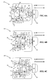
- FIGS. 2A-2C show a bedrail clamp 5 according to embodiments of the present invention.
- the bedrail clamp 5 can attach an accessory to a bedrail 10 of a surgical/medical bed at a desired location without having to slide the bedrail clamp 5 from an end of the bedrail 10 until the accessory is in the desired location.
- the bedrail clamp 5 can be positioned at any location along the bedrail 10 that is not otherwise occupied, and the positioning can occur without having to alter the location of any other accessories or associated bedrail clamps that may be attached to the bedrail 10.
- the bedrail clamp 5 of FIGS. 2A-2C includes a clamp housing 15, an actuating member 20 coupled to the clamp housing 15, and a jaw member 25 pivotably coupled to the actuating member 20 and housed by the clamp housing 15.
- the clamp housing 15 can house other components of the bedrail clamp 5.
- the clamp housing 15 is generally C-shaped and includes a throat area 30.
- the throat area 30 can receive the bedrail 10, and then the bedrail clamp 5 can be closed (as is discussed in greater detail below).
- the throat area 30 of the clamp housing 15 shown in FIGS. 2A-2C includes three bedrail surfaces 35, 36, 37.
- the clamp housing 15 can include a housing guide element, which is discussed in greater detail below.
- the actuating member 20 of the bedrail clamp 5 can coordinate the opening and closing of the bedrail clamp 5.
- the actuating member 20 can be configured to move relative to the clamp housing 15 between a clamp-open position ( FIG. 2A ) and a clamp-closed position ( FIG. 2C ).
- the actuating member 20 can be nearer to the bedrail 10 in the clamp-open position than in the clamp-closed position. Accordingly, to go from the clamp-open position to the clamp- closed position, the actuating member 20 must move in a closing direction, which is indicated as CD in FIGS. 2A-2C .
- the actuating member 20 must move in an opening direction, which is indicated as OD in FIGS. 2A-2C .
- the closing direction CD, the opening direction OD, or both are generally horizontal.
- the jaw member 25 of the bedrail clamp 5 can move between a jaw-open position and a jaw-closed position based on the movement of the actuating member 20.
- the jaw member 25 includes bedrail portions 45, 50 that are configured to interact with the bedrail 10 when in use.
- bedrail portion 45 has a first surface
- bedrail portion 50 has a second surface that is generally perpendicular to the first surface.
- Bedrail portion 45 can be configured to be positioned proximate to the bedrail 10 (i.e., contacting the bedrail 10 or positioned near the bedrail 10 without contacting it) when the jaw member 25 is in the jaw-closed position.
- Bedrail portion 50 can be configured to engage the bedrail 10 when the jaw member 25 is in the jaw-closed position.
- the jaw member 25 can include a guide element, which is discussed in greater detail below.
- FIG. 2A shows the jaw member 25 in the jaw-open position.
- the jaw member 25 does not obstruct the bedrail 10 from entering or exiting the clamp housing's throat area 30.
- the entrance tip 22 of the jaw member 25 can be positioned at the same level as or below the clamp housing's bedrail surface 37 where the bedrail 10 would enter the throat area 30.
- entrance tip 22 of the jaw member 25 in the jaw-open position, can be spaced vertically far enough from the clamp housing's bedrail surface 36 to permit the bedrail 10 to enter the throat area 30.
- Two common bedrail heights are 2,54 centimeters (one inch) and twenty-five centimeters.
- the height of the clamp housing's throat area 30 is slightly larger than those common bedrail heights. In many such embodiments, the vertical distance from bedrail surface 36 to bedrail surface 37 is slightly larger than those common bedrail heights. In some preferred embodiments, the vertical distance from the clamp housing's bedrail surface 36 to the entrance tip 22 of the jaw member 25 is slightly larger than the common bedrail heights when the jaw member 25 is in the jaw-open position.
- the jaw member 25 can move to a jaw-partially-closed position, which, as shown in FIG. 2B , is between the jaw-open position and the jaw-closed position.
- the jaw member 25 In the jaw-partially-closed position, the jaw member 25 obstructs the bedrail 10, when positioned in the clamp housing's throat area 30, from exiting the clamp housing's throat area 30.
- the entrance tip 22 of the jaw member 25 can be brought to a position such that the vertical distance between the entrance tip 22 and bedrail surface 36 of the clamp housing 15 is less than the height of the bedrail 10. But, in the jaw-partially-closed position, the jaw member 25 of the bedrail clamp 5 does not fully engage the bedrail 10.
- either the clamp housing's bedrail surface 35 does not engage the outer surface 60 of the bedrail 10 or bedrail portion 50 of the jaw member 25 does not engage the inner surface 75 of the bedrail 10 (or both).
- the bedrail clamp 5 can be rotated when the jaw member 25 is in the jaw-partially-closed position such that the bedrail 10 can still be removed from the throat area 30.
- the amount of space between bedrail surface 35 and outer surface 60 plus the amount of space between bedrail portion 50 and inner surface 75 is how far the jaw member 25 must be translated in the closing direction to move the jaw member to the jaw-closed position.
- FIG. 2C shows the jaw member 25 in the jaw-closed position.
- the jaw member 25 and the clamp housing 15 can engage the bedrail 10 when the bedrail 10 is positioned in the clamp housing's throat area 30.
- the clamp housing's bedrail surface 35 can engage a generally vertical outer surface 60 of the bedrail 10.
- Bedrail portion 45 of the jaw member 25 can be positioned proximate to a generally horizontal upper surface 65 or a generally horizontal lower surface 70 of the bedrail 10.
- the bedrail clamp 5 can be used as oriented in FIGS.
- FIGS. 2A-2C with the jaw member 25 positioned proximate to the lower surface 70 of the bedrail 10, or the bedrail clamp 5 can be turned upside down such that the jaw member 25 is positioned proximate to the upper surface 65 of the bedrail 10.
- Bedrail surface 36 of the clamp housing 15 can be positioned proximate to whichever of the upper or lower surfaces 65, 70 of the bedrail 10 is not positioned proximate to bedrail portion 45.
- the orientation of FIGS. 2A-2C with bedrail surface 36 positioned proximate to the upper surface 65 and bedrail portion 45 positioned proximate to the lower surface 70, is the preferred orientation.
- bedrail portion 50 of the jaw member 25 can engage a generally vertical inner surface 75 of the bedrail 10 in the jaw-closed position.
- closing the bedrail clamp 5 involves applying force to at least the inner and outer surfaces 75, 60 of the bedrail 10.
- bedrail portions 45, 50 of the jaw member 25 each comprise generally flat surfaces that are perpendicular to one another. In this way, bedrail portion 50 can be substantially flush with the inner surface 75 of the bedrail 10, and bedrail surface 36 of the clamp housing 15 can be substantially flush with the upper surface 65 (or lower surface 70) of the bedrail 10. In this way, the clamping load is distributed across relatively large sections of the inner and outer bedrail surfaces 75, 60, thereby increasing stability and avoiding more acute forces that would cause damage to the bedrail. Many configurations are possible to satisfactorily secure the bedrail clamp 5 to the bedrail 10.
- the bedrail clamp 5 of FIGS. 2A-2C further includes a handle assembly 80, which can permit a user to operate the bedrail clamp 5.
- the handle assembly 80 includes a handle 82 and a handle shaft 84 housed by the clamp housing 15.
- the handle shaft 84 can have a proximal end 86 coupled to the handle 82.
- the handle shaft 84 can have a distal end 88 coupled to the actuating member 20.
- the handle assembly 80 can take a variety of forms.
- the handle assembly 80 is attached to the clamp housing 15 and achieves relative movement between the actuating member 20 and the clamp housing 15 by causing movement of the actuating member 20 relative to the handle assembly 80.
- An example of such an embodiment is shown in FIGS. 2A-2C , with the handle 82 comprising a knob, and the distal end 88 of the handle shaft 84 being threadedly coupled to the actuating member 20.
- turning the knob can cause the actuating member 20 to move between the clamp-open position and the clamp-closed position.
- the handle assembly can be attached to the actuating member and can achieve relative movement between the actuating member and the clamp housing by causing movement of the clamp housing relative to the handle assembly.
- the handle shaft and the clamp housing can include complementary springloaded ratchet components, which can be configured to permit the handle and the handle shaft to move the actuating member between the clamp-open position and the clamp-closed position.
- the handle and the handle shaft are configured to move the actuating member in a ratcheting manner from the clamp-open position to the clamp-closed position.
- the handle and the handle shaft can be configured to move the actuating member via a spring force from the clamp-closed position to the clamp-open position upon release of the complementary springloaded ratchet components.
- the handle can comprise a camming latch that is configured to cam against the clamp housing to move between a camming-latch-open position and a camming-latch-closed position.
- the camming latch is configured to cause the actuating member to move from the clamp-open position to the clamp-closed position as the camming latch moves from the camming-latch-open position to the camming-latch-closed position.
- the pivotable coupling between the jaw member 25 and the actuating member 20 can take a variety of forms.
- the pivotable coupling is discussed with reference to FIG. 4 , which illustrates configurations that can be implemented in single-jaw or double-jaw bedrail clamps.
- the jaw member 25 can include a pivot hole 24 that extends generally parallel to bedrail surface 35 of the clamp housing 15.
- the actuating member 20 can include a pivot pin 27 that extends into the jaw member's pivot hole 24 to pivotably couple the jaw member 25 to the actuating member 20.
- the pivot pin 27 can be integral with the jaw member 25, integral with the actuating member 20, or its own separate component (in which case both the jaw member 25 and the actuating member would have pivot holes).
- the jaw member 25 can include two attachment members 29 that are configured to straddle the actuating member 20, with a separate hinge pin providing the coupling that allows the jaw member 25 to pivot relative to the actuating member.
- the jaw member's attachment members 29 straddling the actuating member 20 can minimize forces that would tend to rotate the actuating member 20 about a horizontal axis that extends between the jaw-open position and the jaw-closed position.
- the exploded view of FIG. 4 shows a preferred arrangement of the pivot pin 27, the pivot hole 24, the attachment members 29 in connection with the actuating member 20 and the jaw member 25.
- both the jaw member 25 and the actuating member 20 can translate relative to the clamp housing 15.
- the clamp housing 15 can include a recessed track 28 that extends generally parallel to the closing direction CD.
- the pivot pin 27 can extend beyond the jaw member 25 into the clamp housing's recessed track 28.
- the pivot pin 27 can be configured to slide within the clamp housing's recessed track 28 to permit the actuating member 20 and the jaw member 25 to translate relative to the clamp housing 15.
- the structure of the clamp housing 15 can be configured to guide the jaw member 25 and the actuating member 20 in translating between open and closed positions.
- movement of the jaw member 25 relative to the clamp housing 15 can be directed by the jaw member's guide element interfacing physically with the clamp housing's guide element.
- the clamp housing's guide element is a recessed track 40
- the jaw member's guide element is a guide pin 55.
- the exploded view of FIG. 4 shows a preferred arrangement of the recessed track 40 and the guide pin 55 (though in the context of a double-jaw bedrail clamp).
- movement of the jaw member 25 relative to the clamp housing 15 is guided by the guide pin 55 sliding within the recessed track 40.
- the recessed track 40 can include a first segment 41 that is generally parallel to the closing direction CD and a second segment 42 that forms a generally obtuse angle with the first segment 41.
- the second segment 42 of the recessed track 40 can be curved.
- the first segment 41 would typically remain straight to guide translation of the jaw member 25 relative to the clamp housing 15. As noted above, movement is typically guided by the guide elements from the jaw-open position to the jaw-partially-closed position to the jaw-closed position (and in reverse as well).
- the clamp housing's guide element and the jaw member's guide element can take a variety of forms.
- the jaw member 25 can include a recessed track
- the clamp housing 15 can include a guide pin.
- both the jaw member 25 and the clamp housing 15 can include a recessed track, and one or more ball bearings can be positioned within both recessed tracks to guide movement.
- the structure of the clamp housing 15 and the structure of the jaw member 25 can include complementary features (e.g., curves, angled segments, etc.) to guide movement as the actuating member 20 moves.
- FIGS. 8A-8C provide an example of such a configuration. In FIGS.
- the clamp housing 15' can include a guiding rail defined in its interior, and the jaw member 25' structure itself can ride along that rail between a jaw-open position and a jaw-closed position.
- a spring 23 can assist in moving from the jaw-closed position to the jaw-open position by.
- FIGS.8A-8C and other similar configurations e.g., those that involve pivoting the jaw member(s)
- FIGS.8A-8C and other similar configurations can be incorporated into a double-jaw clamp as well.
- both the actuating member 20 and the jaw member 25 can be moved between open and closed positions.
- the physical interfacing of the jaw member's guide element and the clamp housing's guide element can reposition the jaw member 25 from the jaw-open position to the jaw-closed position.
- Such physical interfacing can both translate the jaw member 25 in the closing direction CD and pivot the jaw member 25 to reposition the jaw member 25 from the jaw-open position to the jaw-closed position.
- the first movement of the jaw member 25 involves both translation and rotation, and the second movement of the jaw member 25 involves only translation.
- the guide pin 55 slides within the recessed track 40 between the jaw-open position and the jaw-closed position.
- movement of the actuating member 20 in the closing direction CD repositions the jaw member 25 first from the jaw-open position to the jaw-partially-closed position and then from the jaw-partially-closed position to the jaw-closed position.
- repositioning the jaw member 25 from the jaw-open position to the jaw-partially-closed position involves both translating the jaw member 25 in the closing direction CD and pivoting the jaw member 25.
- pivoting the jaw member 25 can involve overcoming a spring force that would resist such rotation.
- repositioning the jaw member 25 from the jaw-partially-closed position to the jaw-closed position involves only translating the jaw member 25 in the closing direction CD.
- FIG. 2A shows the jaw member 25 in the jaw-open position
- FIG. 2B shows the jaw member 25 in the jaw-partially-closed position
- FIG. 2C shows the jaw member 25 in the jaw-closed position.
- FIGS. 5A-5B show a the bedrail clamp 505, with an accessory attachment support 76 that is configured to support an accessory, such as those discussed elsewhere herein.
- the accessory attachment support 76 includes a proximal end housed by the clamp housing 15.
- the accessory attachment support 76 also includes a distal end that extends away from the clamp housing 15 above the bedrail 10 when the bedrail 10 is in the clamp housing's throat area 30 and the jaw member 25 is in the first-jaw-closed position.
- the accessory can be pre-attached to the bedrail clamp.
- the accessory must be attached to the bedrail clamp after the bedrail clamp is attached to the bedrail.
- FIGS. 6A-6C show a bedrail clamp 105 similar to that of FIGS. 2A-2C , with the exception that bedrail clamp 105 includes two jaw members 25, 26.
- jaw member 26 of FIGS. 6A-6C is pivotably coupled to the actuating member 20 and housed by the clamp housing 15.
- the pivotable coupling of jaw member 26 and the actuating member 20 can have similar attributes as discussed elsewhere herein in connection with the pivotable coupling of jaw member 25 and the actuating member 20.
- Jaw member 26 can move between a jaw-open position ( FIG. 6A ), a jaw-partially-closed position ( FIG. 6B ), and a jaw-closed position ( FIG. 6C ) based on the movement of the actuating member 20.
- jaw member 26 includes bedrail portions 46, 51 that are configured to interact with the bedrail 10 when in use.
- Jaw member 26 can include a guide element, which can interface physically with a corresponding guide element in the clamp housing 15 when in use.
- the guide element of jaw member 26 and the guide element of the clamp housing 15 can have similar attributes as guide elements discussed elsewhere herein.
- the guide element combination of jaw member 25 and the clamp housing 15 is the same as the guide element combination of jaw member 26 and the clamp housing, though the two guide element combinations can be different.
- jaw-open position and jaw-closed position of jaw member 26 are similar to those of jaw member 25, as discussed above in connection with FIGS. 2A-2C .
- jaw member 26 in the jaw-open position, jaw member 26 does not obstruct the bedrail 10 from entering or exiting the clamp housing's throat area 30.
- the clamp housing's bedrail surface 35 can engage the outer surface 60 of the bedrail 10.
- bedrail portion 46 of jaw member 26 can be positioned proximate to whichever of the upper surface 65 or the lower surface 70 of the bedrail 10 that is not positioned proximate to bedrail portion 45 of jaw member 25 when in a jaw-closed position.
- bedrail portion 51 can also engage the inner surface 75 of the bedrail 10.
- the bedrail clamp 105 of FIGS. 6A-6C operates similarly to that of FIGS. 2A-2C .
- both jaw member 25 and jaw member 26 are repositioned from jaw-open positions to jaw-closed positions.
- the guide element of jaw member 25 can physically interface with the clamp housing's first guide element to reposition jaw member 25, and the guide element of jaw member 26 can physically interface with the clamp housing's second guide element to reposition jaw member 26. In both cases, such repositioning can be via both translating the jaw members 25, 26 in the closing direction CD and pivoting the jaw members 25, 26.
- FIG. 7 shows a bedrail clamp assembly 700 according to embodiments of the present invention.
- the bedrail clamp assembly 700 includes two clamps 702, 704 separated by a C-block 706.
- Clamps 702, 704 can be structured and can operate similarly to other clamps discussed herein (e.g., bedrail clamp 5 of FIGS. 2A-2C , bedrail clamp 105 of FIGS. 6A-6C , etc.).
- bedrail clamp assembly 700 can be used to clamp larger accessories to a bedrail in a medical setting.
- An example of such a larger accessory is a contrast media injector. Given its larger contact area and its multiple clamps 702, 704, bedrail clamp 700 can provide significantly increased stability in supporting larger accessories.
- the distance between the clamps 702, 704, and thus the size of the C-block 706 can be determined based on the particular application.
- spacer members other than a C-block e.g., rods, top and bottom support members, etc. can be used.
- aspects of the present invention involve methods of attaching an accessory to a bedrail of a surgical/medical bed at a desired location without having to slide the accessory from an end of the bedrail to the desired location.
- a bedrail clamp such as those discussed herein, can be provided in a surgical/medical environment.
- the accessory is attached to the bedrail clamp before the bedrail clamp is attached to the bedrail.
- the accessory must be attached to the bedrail clamp after the bedrail clamp is attached to the bedrail. In either case, an operator can ensure that the actuating member of the bedrail clamp is in the clamp-open position and that any jaw members are in jaw-open positions.
- Clamp-open positions of the actuating member and jaw-open positions of the jaw member(s) are discussed in greater detail elsewhere herein.
- the operator can introduce the bedrail into the throat area of the bedrail clamp's clamp housing without obstruction from the jaw member(s). The operator can do so in accordance with discussion elsewhere herein.
- the operator can close the bedrail clamp.
- the operator can move the actuating member in a closing direction from a clamp-open position to a clamp-closed position.
- the jaw member(s) can be repositioned from the jaw-open position to a jaw-closed position.
- Such repositioning of the jaw member(s) can involve both translating the jaw member(s) in the closing direction and pivoting the jaw member(s). Specific ways of accomplishing such positioning (e.g., via guide elements) are discussed elsewhere herein.
- the jaw-closed position can involve a bedrail surface of the clamp housing engaging a generally vertical outer surface of the bedrail. Attributes of some jaw-closed positions are discussed elsewhere herein. In many cases, when a single-jaw bedrail clamp is used, the jaw-closed position can involve a bedrail portion of the lone jaw member being positioned proximate to either a generally horizontal upper or lower surface of the bedrail and a second bedrail surface of the clamp housing being positioned proximate to whichever of the upper or lower surfaces of the bedrail is not positioned proximate to jaw member's bedrail portion.
- the clamp housing's second bedrail surface is positioned proximate to the bedrail's upper surface, and the lone jaw member's bedrail portion is positioned proximate to the bedrail's lower surface.
- the jaw-closed position can involve a second bedrail portion of the lone jaw member engaging a generally vertical inner surface of the bedrail.
- the second jaw member can interact with the bedrail in the jaw-closed position.
- the jaw-closed position can involve the clamp housing's bedrail surface engaging the outer surface of the bedrail and the first jaw member's bedrail portions being positioned proximate to the upper/lower surface of the bedrail and engaging the inner surface of the bedrail, respectively.
- the jaw-closed position can further involve a bedrail portion of the second jaw member being positioned proximate to whichever of the upper or lower surfaces of the bedrail is not positioned proximate to the first jaw member's first bedrail portion.
- the operator need not determine which jaw member is supposed to be positioned proximate to the bedrail's upper surface and which jaw member is supposed to be positioned proximate to the bedrail's lower surface because the bedrail clamp is substantially symmetrical, with both jaw members being configured to be positioned proximate to either surface of the bedrail.
- the jaw-closed position can further involve a second bedrail portion of the second jaw member engaging the inner surface of the bedrail.
- repositioning the jaw member(s) can involve moving the jaw member(s) through a jaw-partially-closed position, which is between the jaw-open position and the jaw-closed position. Attributes of some jaw-partially-closed positions are discussed elsewhere herein.
- the jaw member(s) In the jaw-partially-closed position, the jaw member(s) can obstruct the bedrail, when positioned in the clamp housing's throat area, from exiting the clamp housing's throat area. But, in the jaw-partially-closed position, the jaw member(s) do not fully engage the bedrail.
- the jaw member(s) can first be repositioned from the jaw-open position to the jaw-partially-closed position. As alluded to elsewhere herein, such repositioning can involve both translating the jaw member(s) in the closing direction and pivoting the jaw member(s). Then, the jaw member(s) can be repositioned from the jaw-partially-closed position to the jaw-closed position. Such repositioning can involve only translating the jaw member(s) in the closing direction.
- the jaw member can first be closed to its final distance from the generally horizontal bedrail surface of the clamp housing, and then the jaw member can be pulled back to press the bedrail against the generally vertical bedrail surface of the clamp housing, thereby accommodating bedrails of varying lengths.
Landscapes
- Engineering & Computer Science (AREA)
- Health & Medical Sciences (AREA)
- General Engineering & Computer Science (AREA)
- Life Sciences & Earth Sciences (AREA)
- Animal Behavior & Ethology (AREA)
- Mechanical Engineering (AREA)
- Veterinary Medicine (AREA)
- Public Health (AREA)
- Surgery (AREA)
- Biomedical Technology (AREA)
- General Health & Medical Sciences (AREA)
- Oral & Maxillofacial Surgery (AREA)
- Molecular Biology (AREA)
- Medical Informatics (AREA)
- Heart & Thoracic Surgery (AREA)
- Pathology (AREA)
- Nuclear Medicine, Radiotherapy & Molecular Imaging (AREA)
- Invalid Beds And Related Equipment (AREA)
- Accommodation For Nursing Or Treatment Tables (AREA)
- Gripping Jigs, Holding Jigs, And Positioning Jigs (AREA)
Claims (15)
- Bettschienenkleinme (5) zum Befestigen eines Zubehörteils an einer Bettschiene (10) eines medizinischen Betts beziehungsweise eines Operationsbetts in einer gewünschten Position ohne die Bettschienenklemme von einem Ende der Bettschiene schieben zu müssen, bis das Zubehörteil in der gewünschten Position ist, wobei die Bettschienenklemme umfasst:(a) ein Klemmgehäuse (15), das (i) einen Halsbereich (30) mit einer ersten Bettschienenoberfläche (35) beinhaltet, der angepasst ist, die Bettschiene aufzunehmen, sowie (ii) ein erstes Gehäuseführungselement (40);(b) ein Betätigungselement (20), das an dem Klemmgehäuse gekoppelt vorliegt und angepasst ist, sich relativ zu dem Klemmgehäuse zwischen einer Position zu bewegen, in der die Klemme geöffnet ist und einer Position, in der die Klemme geschlossen ist, wobei, wenn sich die Bettschiene in dem Halsbereich des Klemmgehäuses befindet, das Betätigungselement in der Klemme geöffnet Position näher an der Bettschiene liegt als in der Klemme geschlossen Position;(c) eine erste Klemmbacke (25), die mit dem Betätigungselement gekoppelt vorliegt und von dem Klemmgehäuse beherbergt wird, wobei die erste Klemmbacke (i) erste (45) und zweite (50) Bettschienenbereiche und (ii) ein erstes Klemmbackenführungselement (55) beinhaltet, das angepasst ist, körperlich mit dem ersten Gehäuseführungselement des Klemmgehäuses gekoppelt zu werden, wenn sich das Betätigungselement in einer Schließrichtung von der Klemme geöffnet Position zu der Klemme geschlossen Position bewegt, um die Position der ersten Klemmbacke von (A) einer erste Backe geöffnet Position, in der die erste Klemmbacke die Bettschiene nicht daran hindert, in den Halsbereich des Klemmgehäuses hineinzugelangen oder ihn zu verlassen, zu (B) einer erste Backe teilweise geschlossen Position und dann, über lediglich ein Umsetzen der ersten Klemmbacke in die Schließrichtung, zu (C) einer erste Backe geschlossen Position zu verändern, in der, wenn sich die Bettschiene in dem Halsbereich des Klemmgehäuses befindet, die erste Bettschienenoberfläche des Klemmgehäuses in eine allgemein vertikale äußere Oberfläche (60) der Bettschiene eingreift, der erste Bettschienenbereich (45) der ersten Klemmbacke dicht an einer allgemein horizontalen oberen (65) oder unteren (70) Oberfläche der Bettschiene angeordnet ist, und der zweite Bettschienenbereich (50) der Klemmbacke in eine allgemein vertikale innere Oberfläche (75) der Bettschiene eingreift.
- Bettschienenklemme nach Anspruch 1, wobei (i) der Halsbereich des Klemmgehäuses ferner eine zweite Bettschienenoberfläche (36) umfasst, und (ii) wenn sich die erste Klemmbacke in der erste Backe geschlossen Position befindet und wenn sich die Bettschiene in dem Halsbereich des Klemmgehäuses befindet, die zweite Bettschienenoberfläche des Klemmgehäuses dicht an der allgemein horizontalen oberen oder unteren Oberfläche der Bettschiene angeordnet ist, je nachdem, welche von beiden nicht dicht an dem ersten Bettschienenbereich der ersten Klemmbacke angeordnet ist.
- Bettschienenklemme nach Anspruch 1, wobei das erste Gehäuseführungselement eine erste vertiefte Schiene (40) umfasst und wobei das erste Klemmbackenführungselement einen ersten Führungsstift (55) umfasst, der angepasst ist, innerhalb der ersten vertieften Schiene zu gleiten, wenn sich das Betätigungselement zwischen der Klemme geöffnet und der Klemme geschlossen Position bewegt.
- Bettschienenklemme nach Anspruch 3, wobei die erste vertiefte Schiene ein erstes Segment (41) umfasst, das allgemein parallel zu der Schließrichtung liegt, sowie ein zweites Segment (42), das mit dem ersten Segment einen allgemein stumpfen Winkel bildet.
- Bettschienenklemme nach Anspruch 1, wobei die erste Klemm teilweise geschlossen Position derart ist, dass die erste Klemmbacke die Bettschiene nicht daran hindert, wenn sie sich in dem Halsbereich des Klemmgehäuses befindet, den Halsbereich des Klemmgehäuses zu verlassen, wobei allerdings die erste Bettschienenoberfläche des Klemmgehäuses die allgemein vertikale äußere Oberfläche der Bettschiene und/oder wobei der zweite Bettschienenbereich der ersten Klemmbacke nicht in die allgemein vertikale innere Oberfläche der Bettschiene eingreift.
- Bettschienenklemme nach Anspruch 1, wobei das Klemmgehäuse ferner umfasst (iii) ein zweites Gehäuse Führungselement, und wobei die Bettschienenklemme ferner umfasst (d) eine zweite Klemmbacke (26), die mit dem Betätigungselement gekoppelt vorliegt und von dem Klemmgehäuse beherbergt wird, wobei die zweite Klemmbacke (i) dritte (46) und vierte (51) Bettschienenbereiche und (ii) ein zweites Klemmbackenführungselement beinhaltet, das angepasst ist, körperlich mit dem zweiten Gehäuseführungselement des Klemmgehäuses gekoppelt zu werden, wenn sich das Betätigungselement in die Schließrichtung von der Klemme geöffnet Position zu der Klemme geschlossen Position bewegt, um die Position der zweiten Klemmbacke über sowohl ein Umsetzen der zweiten Klemmbacke in die Schließrichtung als auch ein Bewegen der zweiten Klemmbacke von (A) einer zweite Backe geöffnet Position, in der die zweite Klemmbacke die Bettschiene nicht daran hindert, in den Halsbereich des Klemmgehäuse hineinzugelangen oder ihn zu verlassen, zu (B) einer zweite Backe geschlossen Position zu verändern, in der, wenn sich die Bettschiene in dem Halsbereich des Klemmgehäuses befindet, die erste Bettschienenoberfläche des Klemmgehäuses in die allgemein vertikale äußere Oberfläche der Bettschiene eingreift, der dritte Bettschienenbereich der zweiten Klemmbacke dicht an derjenigen der allgemein horizontalen oberen oder unteren Oberfläche der Bettschiene angeordnet ist, die nicht dicht an dem ersten Bettschienenbereich der ersten Klemmbacke angeordnet ist, wenn sich die erste Klemmbacke in der ersten Backe geschlossen Position befindet und der vierte Bettschienenbereich der zweiten Klemmbacke in die allgemein vertikale innere Oberfläche der Bettschiene eingreift.
- Bettschienenklemme nach Anspruch 1, wobei die Schließrichtung allgemein horizontal verläuft.
- Bettschienenklemme nach Anspruch 1, wobei der erste Bettschienenbereich der ersten Klemmbacke eine erste Oberfläche umfasst, und der zweite Bettschienenbereich der ersten Klemmbacke eine zweite Oberfläche umfasst, die allgemein rechtwinkelig zu der ersten Oberfläche verläuft.
- Bettschienenklemme nach Anspruch 1, ferner eine Griffanordnung (80) umfassend, die einen Griff (82) und einen Griffstab (84) beinhaltet, der in dem Klemmgehäuse aufgenommen vorliegt, wobei der Griffstab ein proximales Ende (86) aufweist, das mit dem Griff verbunden ist, sowie ein distales Ende (88), das mit dem Betätigungselement (20) verbunden ist.
- Bettschienenklemme nach Anspruch 9, wobei der Griff einen Knauf umfasst und das distale Ende des Griffstabs über ein Gewinde mit dem Betätigungselement gekoppelt ist, so dass ein Drehen des Knaufs dazu führt, dass sich das Betätigungselement zwischen der Klemme geöffnet Position und der Klemme geschlossen Position bewegt.
- Bettschienenklemme nach Anspruch 1, wobei die erste Klemmbacke drehbar mit dem Betätigungselement gekoppelt vorliegt, und wobei das erste Klemmbackenführungselement angepasst ist, körperlich mit dem ersten Gehäuseführungselement gekoppelt zu werden, wenn sich das Betätigungselement in der Schließrichtung von der Klemme geöffnet Position zu der Klemme geschlossen Position bewegt, um die Position der ersten Klemmbacke über sowohl ein Umsetzen der ersten Klemmbacke in die Schließrichtung als auch ein Drehen der ersten Klemmbacke von der erste Backe geöffnet Position zu der erste Backe geschlossen Position zu verändern.
- Bettschienenklemme nach Anspruch 11,
wobei ein Drehstift (27) die erste Klemmbacke an das Betätigungselement koppelt, und wobei das Klemmgehäuse eine vertiefte Schiene (28) beinhaltet, die sich allgemein parallel zur Schließrichtung erstreckt, und wobei sich der Drehstift über die erste Klemmbacke hinaus in die vertiefte Schiene des Klemmgehäuses erstreckt, wobei der Drehstift angepasst ist, in der vertieften Schiene des Klemmgehäuses zu gleiten, um es dem Betätigungselement und der ersten Klemmbacke zu ermöglichen, relativ zu dem Klemmgehäuse versetzt zu werden. - Verfahren zum Anordnen eines Zubehörteils an einer Bettschiene eines medizinischen Betts beziehungsweise eines Operationsbetts in einer gewünschten Position ohne das Zubehörteil von einem Ende der Bettschiene zur gewünschten Position schieben zu müssen, wobei das Verfahren umfasst:(a) Bereitstellen einer Bettschienenklemme nach einem der vorstehenden Ansprüche;(b) Sicherstellen, dass sich das Betätigungselement in der Klemme geöffnet Position befindet und dass sich die erste Klemmbacke in der ersten Backe geöffnet Position befindet;(c) Einführen der Bettschiene in den Halsbereich des Klemmgehäuses ohne Behinderung durch die erste Klemmbacke;(d) Bewegen des Betätigungselements in einer Schließrichtung von der Klemme geöffnet Position zu der Klemme geschlossen Position, dadurch Verändern der Position der ersten Klemmbacke in die erste Backe geschlossen Position.
- Verfahren nach Anspruch 13, wobei (i) die Bettschienenklemme ferner eine zweite Klemmbacke beinhaltet, die mit dem Betätigungselement gekoppelt vorliegt und von dem Klemmgehäuse beherbergt wird, wobei die zweite Klemmbacke dritte und vierte Bettschienenbereiche umfasst, (ii) Einführen der Bettschiene in den Halsbereich des Klemmgehäuses ohne Behinderung durch die zweite Klemmbacke, (iii) das Bewegen des Betätigungselements in der Schließrichtung von der Klemme geöffnet Position zu der Klemme geschlossen Position verändert die Position der zweiten Klemmbacke in eine zweite Backe geschlossen Position, in der die erste Bettschienenoberfläche des Klemmgehäuse in die allgemein vertikale äußere Oberfläche der Bettschiene eingreift, wobei der dritte Bettschienenbereich der zweiten Klemmbacke dicht an derjenigen der allgemein horizontalen oberen oder unteren Oberfläche der Bettschiene angeordnet ist, die nicht dicht an dem ersten Bettschienenbereich der ersten Klemmbacke angeordnet ist, wenn sich die erste Klemmbacke in der ersten Backe geschlossen Position befindet und der vierte Bettschienenbereich der zweiten Klemmbacke in die allgemein vertikale innere Oberfläche der Bettschiene eingreift.
- Verfahren nach Anspruch 13, wobei das Verändern der Position der ersten Klemmbacke von der erste Backe offen Position zu der erste Backe geschlossen Position den Zwischenschritt des Veränderns der Position der ersten Klemmbacke von der erste Backe geöffnet Position zu der erste Backe teilweise geschlossen Position beinhaltet, und wobei das Verändern der Position der ersten Klemmbacke von der erste Backe teilweise geschlossen Position zu der erste Backe geschlossen Position lediglich ein Umsetzen der ersten Klemmbacke umfasst; und/oder
wobei ein Verändern der Position der zweiten Klemmbacke von der zweite Backe geöffnet Position zu der zweite Backe geschlossen Position den Zwischenschritt des Veränderns der Position der zweiten Klemmbacke von der zweite Backe geöffnet Position zu der zweite Backe teilweise geschlossen Position beinhaltet, und wobei das Verändern der Position der zweiten Klemmbacke von der zweite Backe teilweise geschlossen Position zu der zweite Backe geschlossen Position lediglich ein Umsetzen der zweiten Klemmbacke umfasst.
Applications Claiming Priority (3)
| Application Number | Priority Date | Filing Date | Title |
|---|---|---|---|
| US41664910P | 2010-11-23 | 2010-11-23 | |
| US13/176,963 US20120126079A1 (en) | 2010-11-23 | 2011-07-06 | Bedrail clamp |
| PCT/US2011/058219 WO2012096708A1 (en) | 2010-11-23 | 2011-10-28 | Bedrail clamp |
Publications (2)
| Publication Number | Publication Date |
|---|---|
| EP2642940A1 EP2642940A1 (de) | 2013-10-02 |
| EP2642940B1 true EP2642940B1 (de) | 2016-01-06 |
Family
ID=46063431
Family Applications (1)
| Application Number | Title | Priority Date | Filing Date |
|---|---|---|---|
| EP11778781.2A Active EP2642940B1 (de) | 2010-11-23 | 2011-10-28 | Bettschienenklemme |
Country Status (5)
| Country | Link |
|---|---|
| US (1) | US20120126079A1 (de) |
| EP (1) | EP2642940B1 (de) |
| JP (1) | JP5643437B2 (de) |
| CN (1) | CN103370024B (de) |
| WO (1) | WO2012096708A1 (de) |
Families Citing this family (29)
| Publication number | Priority date | Publication date | Assignee | Title |
|---|---|---|---|---|
| US10842485B2 (en) | 2009-10-15 | 2020-11-24 | Covidien Lp | Brachytherapy buttress |
| US9759369B2 (en) | 2011-12-21 | 2017-09-12 | Deka Products Limited Partnership | System, method, and apparatus for clamping |
| US11649924B2 (en) | 2011-12-21 | 2023-05-16 | Deka Products Limited Partnership | System, method, and apparatus for clamping |
| US10655779B2 (en) | 2011-12-21 | 2020-05-19 | Deka Products Limited Partnership | System, method, and apparatus for clamping |
| US10563681B2 (en) | 2011-12-21 | 2020-02-18 | Deka Products Limited Partnership | System, method, and apparatus for clamping |
| CA2876503A1 (en) * | 2012-07-03 | 2014-01-09 | Volcano Corporation | Pim holder with clamping device |
| SG10201607080TA (en) * | 2012-12-21 | 2016-10-28 | Deka Products Lp | System, method, and apparatus for clamping |
| WO2015106232A1 (en) * | 2014-01-13 | 2015-07-16 | Ferno-Washington, Inc. | Accessory clamp for emergency cots |
| US12485052B2 (en) * | 2014-01-22 | 2025-12-02 | Innovative Medical Products, Inc. | Strap clamp assembly |
| US11957628B2 (en) | 2014-01-22 | 2024-04-16 | Innovative Medical Products, Inc. | Strap clamp assembly |
| US20160296401A1 (en) * | 2014-01-22 | 2016-10-13 | Innovative Medical Products, Inc. | Strap clamp assembly |
| JP1529316S (de) | 2014-12-17 | 2015-07-21 | ||
| USD767398S1 (en) | 2014-12-18 | 2016-09-27 | Hisamitsu Pharmaceutical Co., Ltd. | Package |
| USD769121S1 (en) | 2014-12-22 | 2016-10-18 | Hisamitsu Pharmaceutical Co., Inc. | Package |
| JP1537113S (de) | 2015-04-22 | 2015-11-02 | ||
| USD775964S1 (en) | 2015-04-22 | 2017-01-10 | Hisamitsu Pharmaceutical Co., Inc. | Packing box |
| CN104873233A (zh) * | 2015-05-15 | 2015-09-02 | 泰兴市中源医疗器械厂 | 一种手术切口撑开器用立杆夹紧装置 |
| EP4179997A3 (de) | 2015-06-08 | 2023-08-30 | Covidien LP | Befestigungsvorrichtung für chirurgische systeme und verfahren zur verwendung |
| US9585806B2 (en) | 2015-06-11 | 2017-03-07 | Acist Medical Systems, Inc. | Variable rate bedrail clamp |
| US10716726B2 (en) * | 2015-11-09 | 2020-07-21 | Corindus, Inc. | System and apparatus for reacting moments on a bed rail |
| USD801185S1 (en) | 2016-05-18 | 2017-10-31 | Hisamitsu Pharmaceuticals Co., Inc. | Packing box |
| WO2018225788A1 (ja) * | 2017-06-09 | 2018-12-13 | 株式会社メディカロイド | ロボット手術台、及び医療システム |
| WO2019023334A1 (en) * | 2017-07-25 | 2019-01-31 | Smith & Nephew, Inc. | UNIVERSAL CLAMPING DEVICE FOR RAIL |
| US10743961B2 (en) * | 2017-12-29 | 2020-08-18 | Varghese THOMAS | Device for surgical assistance |
| CN110481681B (zh) * | 2018-05-14 | 2021-04-20 | A·肖赫 | 车把夹持装置 |
| US10987193B2 (en) * | 2019-02-06 | 2021-04-27 | Hiwin Technologies Corp. | Clamping device |
| US11248634B2 (en) * | 2019-11-27 | 2022-02-15 | GE Precision Healthcare LLC | Clamping device |
| US12383372B2 (en) * | 2020-06-15 | 2025-08-12 | Boston Scientific Limited | Medical fixation systems and methods of using the same |
| AU2022365471A1 (en) * | 2021-10-11 | 2024-05-02 | Momentis Surgical Ltd. | Rail extension for robotic-surgery devices |
Family Cites Families (14)
| Publication number | Priority date | Publication date | Assignee | Title |
|---|---|---|---|---|
| US1033531A (en) * | 1911-10-24 | 1912-07-23 | Jacob S Brown | Fishing-tool. |
| US2543017A (en) * | 1945-06-23 | 1951-02-27 | John A Hagan | Quick release clamp |
| US2915096A (en) * | 1957-04-08 | 1959-12-01 | Mooney Edward | Hand clamp |
| US3331111A (en) * | 1966-05-06 | 1967-07-18 | Carver & Co Eng | Clamps |
| US4705331A (en) * | 1985-01-11 | 1987-11-10 | Wayne Graham & Associates International, Inc. | Subsea clamping apparatus |
| US4901964A (en) | 1985-01-22 | 1990-02-20 | Mcconnell Bernard E | Rail clamp |
| DE8814208U1 (de) * | 1988-11-12 | 1989-01-05 | Maier, Josef, 7619 Steinach | Klammer zum Verbinden von Schaltafeln |
| US7520007B2 (en) | 2004-11-10 | 2009-04-21 | Allen Medical Systems, Inc. | Accessory rail clamp with latch and lock mechanisms |
| ES2245264B1 (es) * | 2005-04-11 | 2007-03-16 | Sistemas Tecnicos Encofrados, S.A. | Mordaza ajustable para sujecion de paneles de encofrado. |
| ES2249188B1 (es) * | 2005-04-11 | 2006-12-01 | Ingenieria De Encofrados Y Servicios, S.L. | Mordaza para sujecion de paneles de encofrado. |
| US7857271B2 (en) * | 2005-06-24 | 2010-12-28 | Automated Medical Products Corporation | Surgical tool holder with engagement portions |
| CN201140784Y (zh) * | 2007-12-28 | 2008-10-29 | 上海外高桥造船有限公司 | 栏杆夹头 |
| US8313070B2 (en) * | 2008-10-31 | 2012-11-20 | Kronner Richard F | Base-clamp assembly |
| DE102008057336A1 (de) * | 2008-11-14 | 2010-06-02 | Haindl, Hans, Dr. | Klemmhalterung |
-
2011
- 2011-07-06 US US13/176,963 patent/US20120126079A1/en not_active Abandoned
- 2011-10-28 EP EP11778781.2A patent/EP2642940B1/de active Active
- 2011-10-28 WO PCT/US2011/058219 patent/WO2012096708A1/en not_active Ceased
- 2011-10-28 JP JP2013540954A patent/JP5643437B2/ja active Active
- 2011-10-28 CN CN201180065635.4A patent/CN103370024B/zh active Active
Also Published As
| Publication number | Publication date |
|---|---|
| JP5643437B2 (ja) | 2014-12-17 |
| CN103370024A (zh) | 2013-10-23 |
| US20120126079A1 (en) | 2012-05-24 |
| JP2014508546A (ja) | 2014-04-10 |
| CN103370024B (zh) | 2015-12-16 |
| EP2642940A1 (de) | 2013-10-02 |
| HK1188701A1 (zh) | 2014-05-16 |
| WO2012096708A1 (en) | 2012-07-19 |
Similar Documents
| Publication | Publication Date | Title |
|---|---|---|
| EP2642940B1 (de) | Bettschienenklemme | |
| US9585806B2 (en) | Variable rate bedrail clamp | |
| US20230139696A1 (en) | Toolless attachment assembly | |
| US8430889B2 (en) | Puncture needle holder | |
| EP1416897B1 (de) | Ambulanter unterstützender gerätearm | |
| US7673839B2 (en) | Parallel four-bar mechanism | |
| US6179262B1 (en) | Stabilizer assembly for stepper apparatus and ultrasound probe | |
| JP2015519159A (ja) | 腰部の内部人工装具に大腿部を固定するための装置 | |
| JPH03170108A (ja) | スライドアセンブリ用ラッチ装置及びスライドアセンブリ | |
| CN220938089U (zh) | 介入器械操控辅件及介入式医疗系统 | |
| HK1188701B (en) | Bedrail clamp | |
| US12426870B2 (en) | Surgical retractor | |
| JPH07289563A (ja) | 医療器具の保持装置 | |
| JP2012095679A (ja) | 医療用器具の伸縮式保持アーム装置 | |
| CN215780333U (zh) | 一种医用泌尿外科导尿护理设备 | |
| JP2019088756A (ja) | 連結器具 | |
| JP2004181257A (ja) | 医療器具の保持装置 | |
| CN213723238U (zh) | 一种用于木制手术床手臂支撑板活动连接的组件 | |
| JP2004167287A (ja) | 医療器具の保持装置 | |
| JP2004243136A (ja) | 医療器具の保持装置 | |
| JP7643717B2 (ja) | ベッド | |
| JP3136366U (ja) | テレビ取付装置およびこれを備えた収納棚 | |
| BR112020018442B1 (pt) | Respirador | |
| CN121196864A (zh) | 一种手术用可升降的电动头架 | |
| CN118000929A (zh) | 手柄托架 |
Legal Events
| Date | Code | Title | Description |
|---|---|---|---|
| PUAI | Public reference made under article 153(3) epc to a published international application that has entered the european phase |
Free format text: ORIGINAL CODE: 0009012 |
|
| 17P | Request for examination filed |
Effective date: 20130621 |
|
| AK | Designated contracting states |
Kind code of ref document: A1 Designated state(s): AL AT BE BG CH CY CZ DE DK EE ES FI FR GB GR HR HU IE IS IT LI LT LU LV MC MK MT NL NO PL PT RO RS SE SI SK SM TR |
|
| DAX | Request for extension of the european patent (deleted) | ||
| REG | Reference to a national code |
Ref country code: HK Ref legal event code: DE Ref document number: 1188701 Country of ref document: HK |
|
| GRAP | Despatch of communication of intention to grant a patent |
Free format text: ORIGINAL CODE: EPIDOSNIGR1 |
|
| RIC1 | Information provided on ipc code assigned before grant |
Ipc: A61B 19/00 20060101AFI20150624BHEP Ipc: F16B 2/12 20060101ALN20150624BHEP Ipc: F16B 2/10 20060101ALI20150624BHEP Ipc: A61G 13/10 20060101ALI20150624BHEP Ipc: F16M 13/02 20060101ALI20150624BHEP |
|
| INTG | Intention to grant announced |
Effective date: 20150716 |
|
| GRAS | Grant fee paid |
Free format text: ORIGINAL CODE: EPIDOSNIGR3 |
|
| GRAA | (expected) grant |
Free format text: ORIGINAL CODE: 0009210 |
|
| AK | Designated contracting states |
Kind code of ref document: B1 Designated state(s): AL AT BE BG CH CY CZ DE DK EE ES FI FR GB GR HR HU IE IS IT LI LT LU LV MC MK MT NL NO PL PT RO RS SE SI SK SM TR |
|
| REG | Reference to a national code |
Ref country code: GB Ref legal event code: FG4D |
|
| REG | Reference to a national code |
Ref country code: CH Ref legal event code: EP |
|
| REG | Reference to a national code |
Ref country code: IE Ref legal event code: FG4D |
|
| REG | Reference to a national code |
Ref country code: AT Ref legal event code: REF Ref document number: 768164 Country of ref document: AT Kind code of ref document: T Effective date: 20160215 |
|
| REG | Reference to a national code |
Ref country code: DE Ref legal event code: R096 Ref document number: 602011022497 Country of ref document: DE |
|
| REG | Reference to a national code |
Ref country code: NL Ref legal event code: FP |
|
| REG | Reference to a national code |
Ref country code: LT Ref legal event code: MG4D |
|
| REG | Reference to a national code |
Ref country code: AT Ref legal event code: MK05 Ref document number: 768164 Country of ref document: AT Kind code of ref document: T Effective date: 20160106 |
|
| PG25 | Lapsed in a contracting state [announced via postgrant information from national office to epo] |
Ref country code: NO Free format text: LAPSE BECAUSE OF FAILURE TO SUBMIT A TRANSLATION OF THE DESCRIPTION OR TO PAY THE FEE WITHIN THE PRESCRIBED TIME-LIMIT Effective date: 20160406 Ref country code: HR Free format text: LAPSE BECAUSE OF FAILURE TO SUBMIT A TRANSLATION OF THE DESCRIPTION OR TO PAY THE FEE WITHIN THE PRESCRIBED TIME-LIMIT Effective date: 20160106 Ref country code: ES Free format text: LAPSE BECAUSE OF FAILURE TO SUBMIT A TRANSLATION OF THE DESCRIPTION OR TO PAY THE FEE WITHIN THE PRESCRIBED TIME-LIMIT Effective date: 20160106 Ref country code: GR Free format text: LAPSE BECAUSE OF FAILURE TO SUBMIT A TRANSLATION OF THE DESCRIPTION OR TO PAY THE FEE WITHIN THE PRESCRIBED TIME-LIMIT Effective date: 20160407 Ref country code: FI Free format text: LAPSE BECAUSE OF FAILURE TO SUBMIT A TRANSLATION OF THE DESCRIPTION OR TO PAY THE FEE WITHIN THE PRESCRIBED TIME-LIMIT Effective date: 20160106 |
|
| REG | Reference to a national code |
Ref country code: HK Ref legal event code: GR Ref document number: 1188701 Country of ref document: HK |
|
| PG25 | Lapsed in a contracting state [announced via postgrant information from national office to epo] |
Ref country code: PT Free format text: LAPSE BECAUSE OF FAILURE TO SUBMIT A TRANSLATION OF THE DESCRIPTION OR TO PAY THE FEE WITHIN THE PRESCRIBED TIME-LIMIT Effective date: 20160506 Ref country code: AT Free format text: LAPSE BECAUSE OF FAILURE TO SUBMIT A TRANSLATION OF THE DESCRIPTION OR TO PAY THE FEE WITHIN THE PRESCRIBED TIME-LIMIT Effective date: 20160106 Ref country code: LT Free format text: LAPSE BECAUSE OF FAILURE TO SUBMIT A TRANSLATION OF THE DESCRIPTION OR TO PAY THE FEE WITHIN THE PRESCRIBED TIME-LIMIT Effective date: 20160106 Ref country code: LV Free format text: LAPSE BECAUSE OF FAILURE TO SUBMIT A TRANSLATION OF THE DESCRIPTION OR TO PAY THE FEE WITHIN THE PRESCRIBED TIME-LIMIT Effective date: 20160106 Ref country code: SE Free format text: LAPSE BECAUSE OF FAILURE TO SUBMIT A TRANSLATION OF THE DESCRIPTION OR TO PAY THE FEE WITHIN THE PRESCRIBED TIME-LIMIT Effective date: 20160106 Ref country code: PL Free format text: LAPSE BECAUSE OF FAILURE TO SUBMIT A TRANSLATION OF THE DESCRIPTION OR TO PAY THE FEE WITHIN THE PRESCRIBED TIME-LIMIT Effective date: 20160106 Ref country code: RS Free format text: LAPSE BECAUSE OF FAILURE TO SUBMIT A TRANSLATION OF THE DESCRIPTION OR TO PAY THE FEE WITHIN THE PRESCRIBED TIME-LIMIT Effective date: 20160106 Ref country code: IS Free format text: LAPSE BECAUSE OF FAILURE TO SUBMIT A TRANSLATION OF THE DESCRIPTION OR TO PAY THE FEE WITHIN THE PRESCRIBED TIME-LIMIT Effective date: 20160506 |
|
| REG | Reference to a national code |
Ref country code: DE Ref legal event code: R097 Ref document number: 602011022497 Country of ref document: DE |
|
| REG | Reference to a national code |
Ref country code: FR Ref legal event code: PLFP Year of fee payment: 6 |
|
| PG25 | Lapsed in a contracting state [announced via postgrant information from national office to epo] |
Ref country code: EE Free format text: LAPSE BECAUSE OF FAILURE TO SUBMIT A TRANSLATION OF THE DESCRIPTION OR TO PAY THE FEE WITHIN THE PRESCRIBED TIME-LIMIT Effective date: 20160106 Ref country code: DK Free format text: LAPSE BECAUSE OF FAILURE TO SUBMIT A TRANSLATION OF THE DESCRIPTION OR TO PAY THE FEE WITHIN THE PRESCRIBED TIME-LIMIT Effective date: 20160106 |
|
| PLBE | No opposition filed within time limit |
Free format text: ORIGINAL CODE: 0009261 |
|
| STAA | Information on the status of an ep patent application or granted ep patent |
Free format text: STATUS: NO OPPOSITION FILED WITHIN TIME LIMIT |
|
| PG25 | Lapsed in a contracting state [announced via postgrant information from national office to epo] |
Ref country code: RO Free format text: LAPSE BECAUSE OF FAILURE TO SUBMIT A TRANSLATION OF THE DESCRIPTION OR TO PAY THE FEE WITHIN THE PRESCRIBED TIME-LIMIT Effective date: 20160106 Ref country code: SM Free format text: LAPSE BECAUSE OF FAILURE TO SUBMIT A TRANSLATION OF THE DESCRIPTION OR TO PAY THE FEE WITHIN THE PRESCRIBED TIME-LIMIT Effective date: 20160106 Ref country code: CZ Free format text: LAPSE BECAUSE OF FAILURE TO SUBMIT A TRANSLATION OF THE DESCRIPTION OR TO PAY THE FEE WITHIN THE PRESCRIBED TIME-LIMIT Effective date: 20160106 Ref country code: SK Free format text: LAPSE BECAUSE OF FAILURE TO SUBMIT A TRANSLATION OF THE DESCRIPTION OR TO PAY THE FEE WITHIN THE PRESCRIBED TIME-LIMIT Effective date: 20160106 |
|
| 26N | No opposition filed |
Effective date: 20161007 |
|
| PG25 | Lapsed in a contracting state [announced via postgrant information from national office to epo] |
Ref country code: BE Free format text: LAPSE BECAUSE OF FAILURE TO SUBMIT A TRANSLATION OF THE DESCRIPTION OR TO PAY THE FEE WITHIN THE PRESCRIBED TIME-LIMIT Effective date: 20160106 |
|
| PG25 | Lapsed in a contracting state [announced via postgrant information from national office to epo] |
Ref country code: SI Free format text: LAPSE BECAUSE OF FAILURE TO SUBMIT A TRANSLATION OF THE DESCRIPTION OR TO PAY THE FEE WITHIN THE PRESCRIBED TIME-LIMIT Effective date: 20160106 Ref country code: BG Free format text: LAPSE BECAUSE OF FAILURE TO SUBMIT A TRANSLATION OF THE DESCRIPTION OR TO PAY THE FEE WITHIN THE PRESCRIBED TIME-LIMIT Effective date: 20160406 |
|
| REG | Reference to a national code |
Ref country code: CH Ref legal event code: PL |
|
| REG | Reference to a national code |
Ref country code: IE Ref legal event code: MM4A |
|
| PG25 | Lapsed in a contracting state [announced via postgrant information from national office to epo] |
Ref country code: LI Free format text: LAPSE BECAUSE OF NON-PAYMENT OF DUE FEES Effective date: 20161031 Ref country code: CH Free format text: LAPSE BECAUSE OF NON-PAYMENT OF DUE FEES Effective date: 20161031 |
|
| PG25 | Lapsed in a contracting state [announced via postgrant information from national office to epo] |
Ref country code: LU Free format text: LAPSE BECAUSE OF NON-PAYMENT OF DUE FEES Effective date: 20161028 |
|
| REG | Reference to a national code |
Ref country code: FR Ref legal event code: PLFP Year of fee payment: 7 |
|
| PG25 | Lapsed in a contracting state [announced via postgrant information from national office to epo] |
Ref country code: IE Free format text: LAPSE BECAUSE OF NON-PAYMENT OF DUE FEES Effective date: 20161028 |
|
| PG25 | Lapsed in a contracting state [announced via postgrant information from national office to epo] |
Ref country code: CY Free format text: LAPSE BECAUSE OF FAILURE TO SUBMIT A TRANSLATION OF THE DESCRIPTION OR TO PAY THE FEE WITHIN THE PRESCRIBED TIME-LIMIT Effective date: 20160106 Ref country code: HU Free format text: LAPSE BECAUSE OF FAILURE TO SUBMIT A TRANSLATION OF THE DESCRIPTION OR TO PAY THE FEE WITHIN THE PRESCRIBED TIME-LIMIT; INVALID AB INITIO Effective date: 20111028 |
|
| PG25 | Lapsed in a contracting state [announced via postgrant information from national office to epo] |
Ref country code: MC Free format text: LAPSE BECAUSE OF FAILURE TO SUBMIT A TRANSLATION OF THE DESCRIPTION OR TO PAY THE FEE WITHIN THE PRESCRIBED TIME-LIMIT Effective date: 20160106 Ref country code: MK Free format text: LAPSE BECAUSE OF FAILURE TO SUBMIT A TRANSLATION OF THE DESCRIPTION OR TO PAY THE FEE WITHIN THE PRESCRIBED TIME-LIMIT Effective date: 20160106 Ref country code: MT Free format text: LAPSE BECAUSE OF NON-PAYMENT OF DUE FEES Effective date: 20161031 |
|
| REG | Reference to a national code |
Ref country code: FR Ref legal event code: PLFP Year of fee payment: 8 |
|
| PG25 | Lapsed in a contracting state [announced via postgrant information from national office to epo] |
Ref country code: TR Free format text: LAPSE BECAUSE OF FAILURE TO SUBMIT A TRANSLATION OF THE DESCRIPTION OR TO PAY THE FEE WITHIN THE PRESCRIBED TIME-LIMIT Effective date: 20160106 Ref country code: AL Free format text: LAPSE BECAUSE OF FAILURE TO SUBMIT A TRANSLATION OF THE DESCRIPTION OR TO PAY THE FEE WITHIN THE PRESCRIBED TIME-LIMIT Effective date: 20160106 |
|
| RIC2 | Information provided on ipc code assigned after grant |
Ipc: F16B 2/10 20060101ALI20150624BHEP Ipc: F16M 13/02 20060101ALI20150624BHEP Ipc: A61G 13/10 20060101ALI20150624BHEP Ipc: A61B 19/00 20060101AFI20150624BHEP Ipc: F16B 2/12 20060101ALN20150624BHEP |
|
| P01 | Opt-out of the competence of the unified patent court (upc) registered |
Effective date: 20230517 |
|
| PGFP | Annual fee paid to national office [announced via postgrant information from national office to epo] |
Ref country code: NL Payment date: 20251026 Year of fee payment: 15 |
|
| PGFP | Annual fee paid to national office [announced via postgrant information from national office to epo] |
Ref country code: DE Payment date: 20251029 Year of fee payment: 15 |
|
| PGFP | Annual fee paid to national office [announced via postgrant information from national office to epo] |
Ref country code: GB Payment date: 20251027 Year of fee payment: 15 |
|
| PGFP | Annual fee paid to national office [announced via postgrant information from national office to epo] |
Ref country code: IT Payment date: 20251021 Year of fee payment: 15 |
|
| PGFP | Annual fee paid to national office [announced via postgrant information from national office to epo] |
Ref country code: FR Payment date: 20251027 Year of fee payment: 15 |