EP2642128A2 - Compressor - Google Patents
Compressor Download PDFInfo
- Publication number
- EP2642128A2 EP2642128A2 EP13159433.5A EP13159433A EP2642128A2 EP 2642128 A2 EP2642128 A2 EP 2642128A2 EP 13159433 A EP13159433 A EP 13159433A EP 2642128 A2 EP2642128 A2 EP 2642128A2
- Authority
- EP
- European Patent Office
- Prior art keywords
- oil
- oil separation
- passage
- refrigerant gas
- separation compartment
- Prior art date
- Legal status (The legal status is an assumption and is not a legal conclusion. Google has not performed a legal analysis and makes no representation as to the accuracy of the status listed.)
- Granted
Links
Images

Classifications
-
- F—MECHANICAL ENGINEERING; LIGHTING; HEATING; WEAPONS; BLASTING
- F04—POSITIVE - DISPLACEMENT MACHINES FOR LIQUIDS; PUMPS FOR LIQUIDS OR ELASTIC FLUIDS
- F04C—ROTARY-PISTON, OR OSCILLATING-PISTON, POSITIVE-DISPLACEMENT MACHINES FOR LIQUIDS; ROTARY-PISTON, OR OSCILLATING-PISTON, POSITIVE-DISPLACEMENT PUMPS
- F04C29/00—Component parts, details or accessories of pumps or pumping installations, not provided for in groups F04C18/00 - F04C28/00
- F04C29/02—Lubrication; Lubricant separation
-
- F—MECHANICAL ENGINEERING; LIGHTING; HEATING; WEAPONS; BLASTING
- F04—POSITIVE - DISPLACEMENT MACHINES FOR LIQUIDS; PUMPS FOR LIQUIDS OR ELASTIC FLUIDS
- F04B—POSITIVE-DISPLACEMENT MACHINES FOR LIQUIDS; PUMPS
- F04B15/00—Pumps adapted to handle specific fluids, e.g. by selection of specific materials for pumps or pump parts
-
- F—MECHANICAL ENGINEERING; LIGHTING; HEATING; WEAPONS; BLASTING
- F04—POSITIVE - DISPLACEMENT MACHINES FOR LIQUIDS; PUMPS FOR LIQUIDS OR ELASTIC FLUIDS
- F04B—POSITIVE-DISPLACEMENT MACHINES FOR LIQUIDS; PUMPS
- F04B39/00—Component parts, details, or accessories, of pumps or pumping systems specially adapted for elastic fluids, not otherwise provided for in, or of interest apart from, groups F04B25/00 - F04B37/00
- F04B39/04—Measures to avoid lubricant contaminating the pumped fluid
-
- F—MECHANICAL ENGINEERING; LIGHTING; HEATING; WEAPONS; BLASTING
- F04—POSITIVE - DISPLACEMENT MACHINES FOR LIQUIDS; PUMPS FOR LIQUIDS OR ELASTIC FLUIDS
- F04C—ROTARY-PISTON, OR OSCILLATING-PISTON, POSITIVE-DISPLACEMENT MACHINES FOR LIQUIDS; ROTARY-PISTON, OR OSCILLATING-PISTON, POSITIVE-DISPLACEMENT PUMPS
- F04C18/00—Rotary-piston pumps specially adapted for elastic fluids
- F04C18/02—Rotary-piston pumps specially adapted for elastic fluids of arcuate-engagement type, i.e. with circular translatory movement of co-operating members, each member having the same number of teeth or tooth-equivalents
-
- F—MECHANICAL ENGINEERING; LIGHTING; HEATING; WEAPONS; BLASTING
- F04—POSITIVE - DISPLACEMENT MACHINES FOR LIQUIDS; PUMPS FOR LIQUIDS OR ELASTIC FLUIDS
- F04C—ROTARY-PISTON, OR OSCILLATING-PISTON, POSITIVE-DISPLACEMENT MACHINES FOR LIQUIDS; ROTARY-PISTON, OR OSCILLATING-PISTON, POSITIVE-DISPLACEMENT PUMPS
- F04C18/00—Rotary-piston pumps specially adapted for elastic fluids
- F04C18/02—Rotary-piston pumps specially adapted for elastic fluids of arcuate-engagement type, i.e. with circular translatory movement of co-operating members, each member having the same number of teeth or tooth-equivalents
- F04C18/0207—Rotary-piston pumps specially adapted for elastic fluids of arcuate-engagement type, i.e. with circular translatory movement of co-operating members, each member having the same number of teeth or tooth-equivalents both members having co-operating elements in spiral form
- F04C18/0215—Rotary-piston pumps specially adapted for elastic fluids of arcuate-engagement type, i.e. with circular translatory movement of co-operating members, each member having the same number of teeth or tooth-equivalents both members having co-operating elements in spiral form where only one member is moving
-
- F—MECHANICAL ENGINEERING; LIGHTING; HEATING; WEAPONS; BLASTING
- F04—POSITIVE - DISPLACEMENT MACHINES FOR LIQUIDS; PUMPS FOR LIQUIDS OR ELASTIC FLUIDS
- F04C—ROTARY-PISTON, OR OSCILLATING-PISTON, POSITIVE-DISPLACEMENT MACHINES FOR LIQUIDS; ROTARY-PISTON, OR OSCILLATING-PISTON, POSITIVE-DISPLACEMENT PUMPS
- F04C29/00—Component parts, details or accessories of pumps or pumping installations, not provided for in groups F04C18/00 - F04C28/00
- F04C29/02—Lubrication; Lubricant separation
- F04C29/026—Lubricant separation
Definitions
- the present invention relates to a compressor provided with a housing including a compression unit, which draws in refrigerant gas, compresses the refrigerant gas, and then discharges the refrigerant gas from a discharge chamber through an outlet and out of the housing, and an oil separation structure, which is arranged between the discharge chamber and the outlet to separate lubrication oil from the refrigerant gas.
- a typical compressor for a vehicle air conditioner uses lubrication oil, which is suspended in a refrigerant gas, to lubricate parts such as a compression mechanism when the refrigerant gas circulates through the housing of the compressor.
- a compressor includes an oil separation mechanism, which is arranged in a discharge line, to confine the lubrication oil to the compressor and prevent the lubrication oil from escaping into an external refrigerant circuit together with the refrigerant gas.
- Japanese Laid-Open Patent Publication No. 2005-320873 describes an example of a whirling type oil separation structure. Referring to Fig. 9A , in Japanese Laid-Open Patent Publication No.
- an oil separator 80 is arranged in a compression casing 81 between a discharge chamber 82 and an outlet 83.
- the oil separator 80 includes a separation compartment 84 and a separation tube 85.
- the separation tube 85 is press-fitted into and fixed to the separation compartment 84.
- An annular void is formed between the wall surface of the separation compartment 84 and the outer surface of the separation tube 85.
- An oil passage 87 which is in communication with an oil reservoir 86, is formed below the separation compartment 84.
- the refrigerant gas in the discharge chamber 82 enters the separation compartment 84 of the oil separator 80.
- the refrigerant gas then whirls around the outer surface of the separation tube 85 as it descends in the separation compartment 84. This applies centrifugal force to the refrigerant and separates lubrication oil from the refrigerant gas.
- the lubrication oil collects on the wall surface of the separation compartment 84. Then, the refrigerant gas flows through the separation tube 85 and is discharged out of the outlet 83.
- Japanese Laid-Open Patent Publication No. 2009-235910 describes an example of an impingement type oil separation structure.
- a gas compressor 90 described in Japanese Laid-Open Patent Publication No. 2009-235910 includes a casing 91 that accommodates a compression mechanism (not shown) and a baffling passage 92, through which compressed refrigerant gas flows.
- the baffling passage 92 is formed by staggering a series of fin-shaped baffles 94 between the casing 91 and an opposing portion of a rear block 93.
- An oil reservoir (not shown) that accumulates separated lubrication oil is arranged between the casing 91 and the rear block 93.
- the separation tube 85 should have a particular length and diameter to whirl the refrigerant gas about the separation tube 85 in a preferable manner and obtain the required performance for separating lubrication oil.
- the oil separation structure there is a tendency for the oil separation structure to be large, and the freedom of layout is thereby limited
- the baffling passage 92 should have a particular length and a particular number of bent portions 95 to induce refrigerant gas impingement against the bent portions 95 a desired number of times.
- the oil separation structure tends to be large.
- the lubrication oil separated from the baffling passage 92 meanders through the baffling passage 92, the lubrication oil may fill the baffling passage 92. In this case, the lubrication oil may flow backward to the compression mechanism, and the lubrication oil may be carried by the refrigerant gas to the external refrigerant circuit.
- one aspect of the present invention is a compressor including a housing, a compression unit, a discharge chamber, an outlet, and an oil separation structure.
- the compression unit is arranged in the housing and draws in, compresses, and discharges refrigerant gas.
- the discharge chamber is in communication with the compression unit.
- the outlet is in communication with the discharge chamber.
- the outlet is formed in the housing to discharge the refrigerant gas out of the housing.
- the oil separation structure which is arranged between the discharge chamber and the outlet, separates lubrication oil from the refrigerant gas and accumulates separated lubrication oil.
- the oil separation structure includes an oil reservoir that accumulates the lubrication oil separated from the refrigerant gas.
- An oil separation compartment is located upward from the oil reservoir and is in communication with the oil reservoir.
- An intake passage extends upward from the oil separation compartment and is in communication with the discharge chamber. The intake passage draws the refrigerant gas from the discharge chamber into the oil separation compartment to separate the lubrication oil from the refrigerant gas.
- An exhaust passage extends upward from the oil separation compartment and is in communication with the outlet. The exhaust passage discharges the refrigerant gas from the oil separation compartment through the outlet and out of the housing.
- a supply passage extends upward from the oil separation compartment and has a larger cross-sectional area than the intake passage. The supply passage supplies the separated lubrication oil from the oil separation compartment to the oil reservoir.
- refrigerant gas is drawn from the discharge chamber through the intake passage and into the oil separation compartment.
- the intake passage increases the flow velocity of the refrigerant gas.
- the refrigerant gas, of which the flow velocity has been increased blows into the oil separation compartment, the lubrication oil suspended in the refrigerant gas remains on the wall surface of the oil separation compartment due to surface tension.
- the refrigerant gas separated from the lubrication oil is drawn into the exhaust passage, which is in communication with the outlet, and discharged from the oil separation compartment out of the housing.
- the oil separation compartment separates refrigerant gas and lubrication oil and impedes the escape of the separated lubrication oil out of the housing and into the exterior.
- the supply passage has a larger cross-sectional area than the intake passage.
- the lubrication oil separated in the oil separation compartment does not clog the supply passage and can be smoothly supplied from the oil separation compartment to the supply passage.
- the lubrication oil collected on the wall surface of the oil separation compartment is conveyed along the wall surface and supplied to the supply passage. Since the supply passage extends upward from the oil separation compartment, the velocity of the lubrication oil decreases as it moves along the wall surface. This prevents the lubrication oil from the supply passage from entering the oil reservoir with great force.
- the oil separation structure includes three passages in communication with the oil separation compartment.
- the passages have different cross-sectional areas, adjust the flow velocity of the refrigerant gas, and adjust the direction in which the lubrication oil flows. This efficiently separates the lubrication oil and impedes the escape of lubrication oil to the exterior.
- the oil separation structure In addition to the oil separation compartment and the oil reservoir, the oil separation structure merely extends three passages upward from the oil separation compartment. This efficiently separates lubrication oil, and the oil separation structure, which efficiently separates lubrication oil from refrigerant gas, can be reduced in size in the vertical direction.
- the oil separation structure of the present invention can separate lubrication oil from refrigerant gas in the passages and compartments of the housing.
- a separation tube like in a whirling type oil separation structure there is no need for a baffling passage used for refrigerant gas impingement and the arrangement of a large number of impingement sections like in an impingement type oil separation structure.
- the compressor of the present invention allows for reduction in size of the oil separation structure as compared with a whirling type or impingement type oil separation structure. This increases the freedom of layout for the compressor.
- the intake passage, the exhaust passage, and the supply passage are arranged next to one another.
- the exhaust passage is arranged between the intake passage and the supply passage.
- the refrigerant gas flows from the discharge chamber through the intake passage and into the oil separation compartment, which separates lubrication oil from the refrigerant gas. Then, the refrigerant gas is discharged from the oil separation compartment. Further, the exhaust passage is located next to the intake passage. Thus, the refrigerant gas is readily transferred to the exhaust passage.
- the oil separation compartment the lubrication oil is conveyed along the wall surface toward the supply passage. The supply passage is farthest from the intake passage.
- the oil separation compartment efficiently separates refrigerant gas and lubrication oil when the lubrication oil is conveyed along the wall surface.
- the exhaust passage includes an inlet, which is in communication with the oil separation compartment, and a large diameter portion, which is located at a downstream side of the inlet and has a larger cross-sectional area than the inlet.
- the flow velocity of the refrigerant gas, which is drawn into the exhaust passage decreases at the large diameter portion.
- the lubrication oil can be separated from the refrigerant gas when passing through the exhaust passage.
- the oil separation compartment includes a bottom surface that is recessed in an arcuate manner.
- the refrigerant gas which is drawn into the oil separation compartment, whirls along the bottom surface of the oil separation compartment. This separates lubrication oil from the refrigerant gas.
- part of the supply passage which extends from the oil separation compartment, forms a backflow preventing portion that extends back toward the oil separation compartment.
- the oil separation structure includes a bypass passage that communicates the supply passage with a portion of the oil separation structure that is located closer to the exhaust passage than the outlet.
- the refrigerant gas that passes through the exhaust passage enters a portion of the oil separation structure located closer to the exhaust passage than the outlet.
- the lubrication oil carried out of the oil separation compartment is separated from the refrigerant gas.
- the separated lubrication oil is returned to the supply passage through the bypass passage.
- the oil separation structure includes a throttle arranged between the supply passage and the oil reservoir.
- the throttle prevents the refrigerant gas from flowing into the oil reservoir with great force.
- the exhaust passage includes a throttle and a trap.
- the throttle is recessed in the exhaust passage in a direction intersecting a direction in which the refrigerant gas flows through the exhaust passage.
- the trap is located in a portion of the exhaust passage that is closer to the oil separation compartment than the throttle.
- the trap has a larger cross-sectional area than the throttle.
- the housing includes a first wall, which partitions the intake passage and the exhaust passage, and a second wall, which partitions the exhaust passage and the supply passage.
- the first wall and the second wall extend parallel to each other.
- the supply passage extends generally straight upward from the oil separation compartment. This ensures that the lubrication oil separated in the oil separation compartment in decreased in velocity when conveyed along the wall surface of the oil separation compartment. Thus, lubrication oil is prevented from entering the supply passage with great force.
- the compressor further includes a suction chamber, which draws in the refrigerant gas, and an oil supply communication passage, which communicates the suction chamber and the oil reservoir.
- the lubrication oil can be returned through the oil supply communication passage to the suction chamber, which has a lower pressure than the oil reservoir.
- the lubrication oil separated from the refrigerant gas is returned to the refrigerant gas to lubricate the compression unit and the like in a state suspended in the refrigerant gas. Accordingly, the lubrication oil lubricates the compression unit and the like, and the lubrication oil is not carried out of the housing.
- the housing includes a plurality of housing formation members.
- the oil separation compartment and the oil reservoir are formed by coupling the housing formation members.
- the oil separation compartment and oil reservoir are formed over a plurality of housing formation members. This allows for an increase in the volumes of the oil separation compartment and oil reservoir in comparison to when they are formed in, for example, only one housing formation member. Further, the oil separation compartment and oil reservoir can be formed by coupling the housing formation members in a state opposed to each other. This facilitates the manufacturing of the oil separation structure and lowers the cost of the compressor.
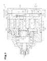
- a scroll compressor 10 which is one embodiment of a compressor according to the present invention, will now be described with reference to Figs. 1 to 4 .
- the scroll compressor 10 is provided with a housing including a center housing 12 (shell), which has a first end and second end, a front housing 11, which is coupled to the first end of the center housing 12, and a rear housing 13, which is coupled to the second end of the center housing 12.
- the front housing 11, center housing 12, and rear housing 13 are fastened together by fasteners B.
- the front housing 11, center housing 12, and rear housing 13 each define a housing formation member that forms the housing of the compressor 10.
- the housing of the scroll compressor 10 includes a scroll type compression unit C that compresses refrigerant gas.
- the center housing 12 is cylindrical and includes a closed end and an open end, which faces the front housing 11.
- a fixed scroll 16, which forms the compression unit C, is fixed in the center housing 12.
- the fixed scroll 16 includes a fixed base plate 14, which forms the closed end of the center housing 12, and a fixed spiral wall 15, which extends from the fixed base plate 14 toward the front housing 11.
- a radial bearing 18 supports the large diameter portion 17a in a rotatable manner.
- the large diameter portion 17a includes an end face 17b that is proximal to the fixed scroll 16.
- An eccentric shaft 19 is formed integrally with the end face 17b.
- the eccentric shaft 19 has an axis separated from that of the rotation shaft 17.
- the eccentric shaft 19 supports a balance weight 20 and bushing 21, which are rotatable relative to each other.
- a movable scroll 23, which forms the compression unit C, is supported by a bearing 24 on the bushing 21.
- the movable scroll 23 is rotatable relative to the bushing 21 and faces the fixed scroll 16.
- the movable scroll 23 includes a movable base plate 25 that faces the fixed base plate 14.
- a compression chamber S having a variable volume is formed in between the fixed base plate 14 and fixed spiral wall 15 of the fixed scroll 16 and the movable base plate 25 and movable spiral wall 26 of the movable scroll 23.
- the fixed base plate 14 includes a discharge port 14a, which is in communication with the compression chamber S.
- a discharge valve 14b is fixed to the fixed base plate 14 to open and close the discharge port 14a.
- a retainer 14c is fixed to the fixed base plate 14 to restrict the open amount of the discharge valve 14b.
- the center housing 12 and rear housing 13 form a discharge chamber 31, which is in communication with the discharge port 14a.
- a suction chamber 30, which serves as a suction portion of the compression unit C, is defined between the circumferential wall of the center housing 12 and the outermost portion in the movable spiral wall of the movable scroll 23. Accordingly, the suction chamber 30 is arranged in the outer section of the compression unit C. Further, the circumferential wall of the center housing 12 includes a suction port 12a, which is in communication with the suction chamber 30.
- the end face of the front housing 11 includes a plurality of rotation restriction holes 11a arranged near the circumference of the movable base plate 25 along the circumferential direction of the movable base plate 25.
- the movable base plate 25 also includes rotation restriction holes 25a arranged along the circumferential direction of the movable base plate 25.
- the number of the rotation restriction holes 25a is the same as the number of the rotation restriction holes 11a. Ends of rotation restriction pins 32 are inserted into the rotation restriction holes 25a.
- the rotation of the rotation shaft 17 and the eccentric shaft 19 produces an orbiting motion of the movable scroll 23.
- Refrigerant gas which is drawn through the suction port 12a into the suction chamber 30, enters the gaps between the fixed base plate 14 and the movable base plate 25.
- the circumferential surface of each rotation restriction pin 32 slides along the wall surfaces of the rotation restriction holes 11a and 25a.
- the movable scroll 23 orbits without rotating.
- the orbiting of the movable scroll 23 converges the compression chamber S toward inner terminal ends of the spiral walls 15 and 26 in the two scrolls 16 and 23, while decreasing the volume of the compression chamber S.
- the decrease in the volume of the compression chamber S compresses the refrigerant gas, which is discharged out of the discharge port 14a and into the discharge chamber 31.
- a muffler compartment 40 As shown in Fig. 3 , when the center housing 12 and rear housing 13 are coupled, a muffler compartment 40, an oil separation compartment 41, an oil reservoir 44, an intake passage 46, an exhaust passage 47, and a supply passage 48 are formed in the housing.
- the fixed base plate 14 in the center housing 12 includes an annular center housing circumferential wall 12c, which projects toward the rear housing 13 from the circumference of the fixed base plate 14.
- the rear housing 13 includes a closed end 13a.
- An annular rear housing circumferential wall 13c projects from the circumference of the closed end 13a toward the center housing circumferential wall 12c.
- a gasket 50 is held between the center housing 12 and rear housing 13. The gasket 50 impedes the leakage of refrigerant gas and lubrication oil from the muffler compartment 40, the oil separation compartment 41, the oil reservoir 44, the exhaust passage 47, and the supply passage 48.
- a vertically lower portion in the fixed base plate 14 includes a first wall 12d, which extends laterally from a portion of the center housing circumferential wall 12c and then curves upward.
- a vertically lower portion in the closed end 13a of the rear housing 13 includes a first wall 13d, which extends laterally from part of the rear housing circumferential wall 13c and then curves upward.
- the first wall 13d includes a distal portion that is arcuate and curved upward.
- a vertically upper portion in the fixed base plate 14 includes a second wall 12e, which connects two locations on the center housing circumferential wall 12c.
- the fixed base plate 14, the second wall 12e, and the center housing circumferential wall 12c encompass a void that forms a part of the muffler compartment 40.
- a partition wall 12k (partition) extends from the second wall 12e toward the first wall 12d.
- a clearance is formed between a distal end of the partition wall 12k and the first wall 12d.
- the partition wall 12k includes a hollow passage formation portion 12ka, which extends in the vertical direction.
- a vertically upper portion in the closed end 13a of the rear housing 13 includes a second wall 13e, which connects two locations on the rear housing circumferential wall 13c.
- the closed end 13a, second wall 13e, and rear housing circumferential wall 13c encompass a void that forms part of the muffler compartment 40.
- a partition wall 13k (partition) extends from the second wall 13e toward the first wall 13d.
- a clearance is formed between a distal end of the partition wall 13k and the first wall 13d.
- the partition wall 13k includes a hollow passage formation portion 13ka, which extends in the vertical direction.
- the center housing 12 and rear housing 13 are coupled, and the two muffler compartments 40 are joined with each other.
- a single muffler compartment 40 is formed in the housing.
- the muffler compartment 40 is in communication with an outlet 12g, which is formed in the center housing circumferential wall 12c.
- the outlet 12g leads to the exterior of the housing.
- the fixed base plate 14 includes a third wall 12f that extends in the vertical direction and connects the first wall 12d and second wall 12e.
- the third wall 12f has a clearance of a fixed distance from the partition wall 12k.
- Part of the intake passage 46 is formed between the fixed base plate 14, third wall 12f, and partition wall 12k.
- An intake port formation recess 12fa is formed in an upper portion of the third wall 12f.
- the fixed base plate 14, center housing circumferential wall 12c, first wall 12d, second wall 12e, and third wall 12f encompass a void that forms part of the discharge chamber 31.
- the fixed base plate 14, distal portion of the first wall 12d, third wall 12f, partition wall 12k, and center housing circumferential wall 12c encompass part of a continuous oil separation void T.
- the closed end 13a of the rear housing 13 includes a third wall 13f that extends in the vertical direction and connects the first wall 13d and the second wall 13e.
- the third wall 13f has a clearance of a fixed distance from the partition wall 13k.
- Part of the intake passage 46 is formed between the closed end 13a, the third wall 13f, and the partition wall 13k.
- An intake port formation recess 13fa is formed in an upper portion of the third wall 13f.
- the closed end 13a, the rear housing circumferential wall 13c, the first wall 13d, the second wall 13e, and the third wall 13f encompass a void that forms part of the discharge chamber 31. Further, the closed end 13a, the distal portion of the first wall 13d, the third wall 13f, the partition wall 13k, and the rear housing circumferential wall 13c encompass part of a continuous oil separation void T.
- the two discharge chambers 31 are joined with each other to form a single discharge chamber 31 in the housing.
- the two intake passages 46 are joined with each other to form a single intake passage 46 in the housing.
- the intake port formation recesses 12fa and 13fa are also joined with each other thereby forming an intake port 46a, which communicates the discharge chamber 31 and the intake passage 46.
- the two passage formation portions 12ka and 13ka are joined with each other to form the exhaust passage 47 in the housing.
- the two oil separation voids T are joined with each other to form a single oil separation void T in the housing.
- the oil separation void T includes a section forming the oil separation compartment 41 that is located below the intake passage 46 and exhaust passage 47 and encompassed by the distal portions of the first walls 12d and 13d.
- the oil separation void T also includes a section forming the supply passage 48, which extends diagonally upward from the oil separation compartment 41.
- the oil separation void T includes a section forming the oil reservoir 44 that is located downward from the supply passage 48 and below the first walls 12d and 13d.
- the intake passage 46, oil separation compartment 41, exhaust passage 47, supply passage 48, and oil reservoir 44 form an oil separation structure arranged between the discharge chamber 31 and the outlet 12g.
- the intake passage 46, exhaust passage 47, oil separation compartment 41, supply passage 48, and oil reservoir 44 will now be described in detail.
- the intake passage 46 includes one end in communication with the discharge chamber 31 through the intake port 46a and another end in communication with the oil separation compartment 41. Accordingly, the intake passage 46 extends upward from the oil separation compartment 41 and is in communication with the discharge chamber 31.
- the intake passage 46 has a smaller diameter (i.e., cross-sectional area) than the discharge chamber 31. Refrigerant gas is drawn from the discharge chamber 31 through the intake port 46a into the intake passage 46.
- the exhaust passage 47 includes one end, which is in communication with the oil separation compartment 41, and another end, which is in communication with the muffler compartment 40. Accordingly, the exhaust passage 47 extends upward from the oil separation compartment 41 and is in communication with the muffler compartment 40.
- the end of the exhaust passage 47 that is in communication with the oil separation compartment 41 defines an inlet 47a into which refrigerant gas flows from the oil separation compartment 41.
- the portion of the exhaust passage 47 other than the inlet 47a forms a large diameter portion having a larger diameter (i.e., cross-sectional area) than the inlet 47a.
- the refrigerant gas drawn into the oil separation compartment 41 enters the inlet 47a of the exhaust passage 47. Then, the refrigerant gas expands at the large diameter portion. This decreases the flow velocity of the refrigerant gas. In this state, the refrigerant gas enters the muffler compartment 40.
- the supply passage 48 extends upward from the oil separation compartment 41. More specifically, the supply passage 48 extends diagonally upward from the intake passage 46 at the oil separation compartment 41. Thus, the lubrication oil in the oil separation compartment 41 is conveyed diagonally upward along the wall surface of the oil separation compartment 41 and supplied to the supply passage 48.
- the supply passage 48 has a larger diameter (i.e., cross-sectional area) than the intake passage 46 and the exhaust passage 47 (inlet 47a).
- the intake passage 46, exhaust passage 47, and supply passage 48 are arranged in this order from the discharge chamber 31, and the exhaust passage 47 is arranged between the intake passage 46 and the supply passage 48.
- the oil reservoir 44 is arranged below the supply passage 48.
- the oil reservoir 44 is a compartment for accumulating the lubrication oil that falls from the supply passage 48.
- the supply passage 48 is arranged in the housing extending diagonally upward from the oil separation compartment 41, that is, in a direction intersecting the vertical direction of the oil separation compartment 41. Further, the oil reservoir 44 is arranged in the housing to extend downward from beside the oil separation compartment 41.
- the discharge chamber 31 is arranged diagonally upward from the oil separation compartment 41.
- the center housing circumferential wall 12c of the center housing 12 includes an oil supply communication passage 12h, which communicates the oil reservoir 44 and the suction chamber 30.
- the oil supply communication passage 12h extends over one half of the center housing circumferential wall 12c.
- the refrigerant gas compressed in the compression unit C and discharged into the discharge chamber 31 enters the intake passage 46 through the intake port 46a and is drawn into the oil separation compartment 41 through the intake passage 46.
- the refrigerant gas is forced from the intake passage 46, which has a small diameter, into the oil separation compartment 41, which is a vast void, thereby increasing the flow velocity of the refrigerant gas.
- turbulence of the refrigerant gas is suppressed in the intake passage 46.
- the refrigerant gas flows toward the oil separation compartment 41 in a laminar state at a substantially uniform velocity and blows into the oil separation compartment 41 through the outlet of the intake passage 46.
- the refrigerant gas forces the lubrication oil on the wall surface of the oil separation compartment 41 away from the intake passage 46.
- the lubrication oil is conveyed along the bottom surface of the oil separation compartment 41 toward the supply passage 48.
- the refrigerant gas is directed upward along the bottom surface of the oil separation compartment 41 and drawn into the exhaust passage 47, which is in communication with the outlet 12g.
- the refrigerant gas forced into the oil separation compartment 41 is readily discharged from the exhaust passage 47 into the muffler compartment 40. Then, the refrigerant gas is discharged from the muffler compartment 40 through the outlet 12g and out of the housing of the scroll compressor 10.
- the lubrication oil conveyed along the wall surface of the oil separation compartment 41 is directly supplied to the supply passage 48.
- the supply passage 48 has a larger diameter (i.e., cross-sectional area) than the intake passage 46 and the exhaust passage 47. This prevents the supply passage 48 from being filled with lubrication oil and smoothly supplies the supply passage 48 with lubrication oil. Then, the lubrication oil of the oil reservoir 44 is supplied through the oil supply communication passage 12h to the suction chamber 30.
- the oil separation compartment 41, the oil reservoir 44, the intake passage 46, the exhaust passage 47, and the supply passage 48 extend over the center housing 12 and the rear housing 13.
- the oil separation compartment 41, the oil reservoir 44, the intake passage 46, the exhaust passage 47, and the supply passage 48 may be formed in only the rear housing 13 or the center housing 12.
- part of the supply passage 48 may be expanded to form a backflow preventing portion 48a that extends back toward the oil separation compartment 41 from the supply passage 48. More specifically, part of the partition walls 12k and 13k are cut out toward the oil separation compartment 41, and the cut out portion forms the backflow preventing portion 48a.
- the lubrication oil flows along the wall surface of the supply passage 48, even if the lubrication oil flows backward toward the oil separation compartment 41, the lubrication oil would enter the backflow preventing portion 48a. This decreases the amount of lubrication oil that flows backward from the supply passage 48 to the oil separation compartment 41.
- a bypass passage 60 may communicate the muffler compartment 40, which is a portion closer to the exhaust passage 47 than the outlet 12g, and the supply passage 48.
- the refrigerant gas from the exhaust passage 47 expands.
- the expansion of the refrigerant gas in the muffler compartment 40 separates lubrication oil from the refrigerant gas.
- the separated lubrication oil in the muffler compartment 40 can be returned to the supply passage 48 through the bypass passage 60. This impedes the escape of lubrication oil from the housing of the scroll compressor 10.
- a throttle 51 may be arranged between the supply passage 48 and the oil reservoir 44.
- the throttle 51 prevents the refrigerant gas from flowing into the oil reservoir 44 with great force and prevents the refrigerant gas from disturbing the oil surface in the oil reservoir 44.
- the bottom surface of the oil separation compartment 41 does not have to be recessed in an arcuate manner.
- the oil separation compartment 41 may be box-shaped.
- the exhaust passage 47 may include a throttle 53 formed by recessing the exhaust passage 47 in a direction intersecting the flow direction of the refrigerant gas in the exhaust passage 47.
- a trap 56a which has a larger diameter than the throttle 53, is formed in the portion of the exhaust passage 47 closer to the oil separation compartment 41 than the throttle 53 of the exhaust passage 47. That is, the trap 56a is located at the upstream side of the throttle 53 in the exhaust passage 47.
- the exhaust passage 47 includes the trap 56a and the throttle 53, which are formed continuously in the flow direction of the refrigerant gas, and the throttle 53 is formed at the downstream side of the trap 56a.
- the throttle 53 is formed by reducing the diameter of the exhaust passage 47 in a tapered manner toward the oil separation compartment 41.
- the trap 56a extends along the circulation direction of the refrigerant gas in the exhaust passage 47.
- portions (first walls 121 k) partitioning the intake passage 46 and the exhaust passage 47 may be formed parallel to portions (second wall 122k) partitioning the exhaust passage 47 and the supply passage 48.
- the exhaust passage 47 extends backward at 180 degrees from the intake passage 46.
- part of the supply passage 48 extends backward at 180 degrees from the intake passage 46.
- part of the supply passage 48 (portion of the supply passage 48 proximal to the oil separation compartment 41) extends straight upward. This further ensures a decrease in the velocity of the lubrication, which is separated from the refrigerant gas in the oil separation compartment 41, conveyed along the wall surface of the oil separation compartment 41 toward the supply passage 48 and prevents the lubrication oil from entering the supply passage 48 with great force.
- the intake passage 46, exhaust passage 47, and supply passage 48 are arranged in order from the discharge chamber 31.
- the arrangement order of the intake passage 46, exhaust passage 47, and supply passage 48 may be changed.
- the compression unit C is of a scroll type.
- the compression unit C may be of a vane type.
Landscapes
- Engineering & Computer Science (AREA)
- Mechanical Engineering (AREA)
- General Engineering & Computer Science (AREA)
- Applications Or Details Of Rotary Compressors (AREA)
- Compressor (AREA)
Abstract
Description
- The present invention relates to a compressor provided with a housing including a compression unit, which draws in refrigerant gas, compresses the refrigerant gas, and then discharges the refrigerant gas from a discharge chamber through an outlet and out of the housing, and an oil separation structure, which is arranged between the discharge chamber and the outlet to separate lubrication oil from the refrigerant gas.
- A typical compressor for a vehicle air conditioner uses lubrication oil, which is suspended in a refrigerant gas, to lubricate parts such as a compression mechanism when the refrigerant gas circulates through the housing of the compressor. Thus, such a compressor includes an oil separation mechanism, which is arranged in a discharge line, to confine the lubrication oil to the compressor and prevent the lubrication oil from escaping into an external refrigerant circuit together with the refrigerant gas. Japanese Laid-Open Patent Publication No.
2005-320873 Fig. 9A , in Japanese Laid-Open Patent Publication No.2005-320873 compression casing 81 between adischarge chamber 82 and anoutlet 83. The oil separator 80 includes aseparation compartment 84 and a separation tube 85. The separation tube 85 is press-fitted into and fixed to theseparation compartment 84. An annular void is formed between the wall surface of theseparation compartment 84 and the outer surface of the separation tube 85. Anoil passage 87, which is in communication with anoil reservoir 86, is formed below theseparation compartment 84. - The refrigerant gas in the
discharge chamber 82 enters theseparation compartment 84 of the oil separator 80. The refrigerant gas then whirls around the outer surface of the separation tube 85 as it descends in theseparation compartment 84. This applies centrifugal force to the refrigerant and separates lubrication oil from the refrigerant gas. The lubrication oil collects on the wall surface of theseparation compartment 84. Then, the refrigerant gas flows through the separation tube 85 and is discharged out of theoutlet 83. - Japanese Laid-Open Patent Publication No.
2009-235910 Fig. 9B , agas compressor 90 described in Japanese Laid-Open Patent Publication No.2009-235910 casing 91 that accommodates a compression mechanism (not shown) and abaffling passage 92, through which compressed refrigerant gas flows. Thebaffling passage 92 is formed by staggering a series of fin-shaped baffles 94 between thecasing 91 and an opposing portion of arear block 93. An oil reservoir (not shown) that accumulates separated lubrication oil is arranged between thecasing 91 and therear block 93. - When refrigerant gas flows through the
baffling passage 92, the refrigerant gas repetitively impinges againstbent portions 95 formed between thebaffles 94. The difference in specific gravity separates lubrication oil from the refrigerant gas. The refrigerant gas is discharged out of thegas compressor 90, whereas the lubrication oil is accumulated in the oil reservoir. - In the whirling type oil separation structure such as the oil separator 80 of Japanese Laid-Open Patent Publication No.
2005-320873 - In the impingement type oil separation structure such as that of Japanese Laid-Open Patent Publication No.
2009-235910 baffling passage 92, thebaffling passage 92 should have a particular length and a particular number ofbent portions 95 to induce refrigerant gas impingement against the bent portions 95 a desired number of times. Thus, the oil separation structure tends to be large. Further, as the lubrication oil separated from thebaffling passage 92 meanders through thebaffling passage 92, the lubrication oil may fill thebaffling passage 92. In this case, the lubrication oil may flow backward to the compression mechanism, and the lubrication oil may be carried by the refrigerant gas to the external refrigerant circuit. - It is an object of the present invention to provide a compressor that allows an oil separation mechanism to be reduced in size, have a higher freedom of layout, and impede the escape of lubrication oil from the compressor.
- To achieve the above object, one aspect of the present invention is a compressor including a housing, a compression unit, a discharge chamber, an outlet, and an oil separation structure. The compression unit is arranged in the housing and draws in, compresses, and discharges refrigerant gas. The discharge chamber is in communication with the compression unit. The outlet is in communication with the discharge chamber. The outlet is formed in the housing to discharge the refrigerant gas out of the housing. The oil separation structure, which is arranged between the discharge chamber and the outlet, separates lubrication oil from the refrigerant gas and accumulates separated lubrication oil. The oil separation structure includes an oil reservoir that accumulates the lubrication oil separated from the refrigerant gas. An oil separation compartment is located upward from the oil reservoir and is in communication with the oil reservoir. An intake passage extends upward from the oil separation compartment and is in communication with the discharge chamber. The intake passage draws the refrigerant gas from the discharge chamber into the oil separation compartment to separate the lubrication oil from the refrigerant gas. An exhaust passage extends upward from the oil separation compartment and is in communication with the outlet. The exhaust passage discharges the refrigerant gas from the oil separation compartment through the outlet and out of the housing. A supply passage extends upward from the oil separation compartment and has a larger cross-sectional area than the intake passage. The supply passage supplies the separated lubrication oil from the oil separation compartment to the oil reservoir.
- In the above structure, refrigerant gas is drawn from the discharge chamber through the intake passage and into the oil separation compartment. The intake passage increases the flow velocity of the refrigerant gas. When the refrigerant gas, of which the flow velocity has been increased, blows into the oil separation compartment, the lubrication oil suspended in the refrigerant gas remains on the wall surface of the oil separation compartment due to surface tension. Thus, the refrigerant gas separated from the lubrication oil is drawn into the exhaust passage, which is in communication with the outlet, and discharged from the oil separation compartment out of the housing. In this manner, the oil separation compartment separates refrigerant gas and lubrication oil and impedes the escape of the separated lubrication oil out of the housing and into the exterior.
- Further, the supply passage has a larger cross-sectional area than the intake passage. Thus, the lubrication oil separated in the oil separation compartment does not clog the supply passage and can be smoothly supplied from the oil separation compartment to the supply passage. Moreover, the lubrication oil collected on the wall surface of the oil separation compartment is conveyed along the wall surface and supplied to the supply passage. Since the supply passage extends upward from the oil separation compartment, the velocity of the lubrication oil decreases as it moves along the wall surface. This prevents the lubrication oil from the supply passage from entering the oil reservoir with great force. In this manner, the oil separation structure includes three passages in communication with the oil separation compartment. The passages have different cross-sectional areas, adjust the flow velocity of the refrigerant gas, and adjust the direction in which the lubrication oil flows. This efficiently separates the lubrication oil and impedes the escape of lubrication oil to the exterior. In addition to the oil separation compartment and the oil reservoir, the oil separation structure merely extends three passages upward from the oil separation compartment. This efficiently separates lubrication oil, and the oil separation structure, which efficiently separates lubrication oil from refrigerant gas, can be reduced in size in the vertical direction.
- The oil separation structure of the present invention can separate lubrication oil from refrigerant gas in the passages and compartments of the housing. Thus, there is no need for a separation tube like in a whirling type oil separation structure. Further, in the oil separation structure of the present invention, there is no need for a baffling passage used for refrigerant gas impingement and the arrangement of a large number of impingement sections like in an impingement type oil separation structure. Thus, the compressor of the present invention allows for reduction in size of the oil separation structure as compared with a whirling type or impingement type oil separation structure. This increases the freedom of layout for the compressor.
- Preferably, the intake passage, the exhaust passage, and the supply passage are arranged next to one another. Further, the exhaust passage is arranged between the intake passage and the supply passage.
- In the above structure, the refrigerant gas flows from the discharge chamber through the intake passage and into the oil separation compartment, which separates lubrication oil from the refrigerant gas. Then, the refrigerant gas is discharged from the oil separation compartment. Further, the exhaust passage is located next to the intake passage. Thus, the refrigerant gas is readily transferred to the exhaust passage. In the oil separation compartment, the lubrication oil is conveyed along the wall surface toward the supply passage. The supply passage is farthest from the intake passage. Thus, the oil separation compartment efficiently separates refrigerant gas and lubrication oil when the lubrication oil is conveyed along the wall surface.
- Preferably, the exhaust passage includes an inlet, which is in communication with the oil separation compartment, and a large diameter portion, which is located at a downstream side of the inlet and has a larger cross-sectional area than the inlet.
- In the above structure, the flow velocity of the refrigerant gas, which is drawn into the exhaust passage, decreases at the large diameter portion. Thus, even when lubrication oil is suspended in the refrigerant gas that is drawn into the exhaust passage, the lubrication oil can be separated from the refrigerant gas when passing through the exhaust passage.
- Preferably, the oil separation compartment includes a bottom surface that is recessed in an arcuate manner.
- In the above structure, the refrigerant gas, which is drawn into the oil separation compartment, whirls along the bottom surface of the oil separation compartment. This separates lubrication oil from the refrigerant gas.
- Preferably, part of the supply passage, which extends from the oil separation compartment, forms a backflow preventing portion that extends back toward the oil separation compartment.
- In the above structure, when lubrication oil is conveyed along the wall surface of the supply passage, even if the lubrication oil flows back toward the oil separation compartment, the lubrication oil flows into the backflow preventing portion. This decreases the amount of lubrication oil that flows backward from the supply passage to the oil separation compartment.
- Preferably, the oil separation structure includes a bypass passage that communicates the supply passage with a portion of the oil separation structure that is located closer to the exhaust passage than the outlet.
- In the above structure, the refrigerant gas that passes through the exhaust passage enters a portion of the oil separation structure located closer to the exhaust passage than the outlet. Here, the lubrication oil carried out of the oil separation compartment is separated from the refrigerant gas. The separated lubrication oil is returned to the supply passage through the bypass passage.
- Preferably, the oil separation structure includes a throttle arranged between the supply passage and the oil reservoir.
- In the above structure, even when refrigerant gas flows into the supply passage, the throttle prevents the refrigerant gas from flowing into the oil reservoir with great force.
- Preferably, the exhaust passage includes a throttle and a trap. The throttle is recessed in the exhaust passage in a direction intersecting a direction in which the refrigerant gas flows through the exhaust passage. The trap is located in a portion of the exhaust passage that is closer to the oil separation compartment than the throttle.
- The trap has a larger cross-sectional area than the throttle.
- In the above structure, when lubrication oil is carried into the exhaust passage and conveyed along the wall surface of the exhaust passage, the lubrication oil enters the trap. This prevents the lubrication oil from flowing further downstream from the throttle.
- Preferably, the housing includes a first wall, which partitions the intake passage and the exhaust passage, and a second wall, which partitions the exhaust passage and the supply passage. The first wall and the second wall extend parallel to each other.
- In the above structure, the supply passage extends generally straight upward from the oil separation compartment. This ensures that the lubrication oil separated in the oil separation compartment in decreased in velocity when conveyed along the wall surface of the oil separation compartment. Thus, lubrication oil is prevented from entering the supply passage with great force.
- Preferably the compressor further includes a suction chamber, which draws in the refrigerant gas, and an oil supply communication passage, which communicates the suction chamber and the oil reservoir.
- In the above structure, after the oil separation structure separates lubrication oil from the refrigerant gas, the lubrication oil can be returned through the oil supply communication passage to the suction chamber, which has a lower pressure than the oil reservoir. Thus, the lubrication oil separated from the refrigerant gas is returned to the refrigerant gas to lubricate the compression unit and the like in a state suspended in the refrigerant gas. Accordingly, the lubrication oil lubricates the compression unit and the like, and the lubrication oil is not carried out of the housing.
- Preferably, the housing includes a plurality of housing formation members. The oil separation compartment and the oil reservoir are formed by coupling the housing formation members.
- In this structure, the oil separation compartment and oil reservoir are formed over a plurality of housing formation members. This allows for an increase in the volumes of the oil separation compartment and oil reservoir in comparison to when they are formed in, for example, only one housing formation member. Further, the oil separation compartment and oil reservoir can be formed by coupling the housing formation members in a state opposed to each other. This facilitates the manufacturing of the oil separation structure and lowers the cost of the compressor.
- Other aspects and advantages of the present invention will become apparent from the following description, taken in conjunction with the accompanying drawings, illustrating by way of example the principles of the invention.
- The invention, together with objects and advantages thereof, may best be understood by reference to the following description of the presently preferred embodiments together with the accompanying drawings in which:
-
Fig. 1 is a cross-sectional view showing a compressor according to one embodiment of the present invention; -
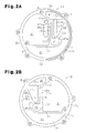
Fig. 2A is a cross-sectional view taken alongline 2A-2A inFig. 1 ; -
Fig. 2B is a cross-sectional view taken alongline 2B-2B inFig. 1 ; -
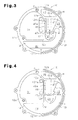
Fig. 3 is a cross-sectional view showing an oil separation structure of the compressor ofFig. 1 ; -
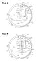
Fig. 4 is a diagram showing another example of a supply passage ofFig. 3 ; -
Fig. 5 is a diagram showing an example of a bypass passage that communicates an outlet and the supply passage; -
Fig. 6 is a diagram showing an example of a throttle arranged between the supply passage and an oil reservoir; -
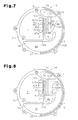
Fig. 7 is a diagram showing an example of a trap arranged in an exhaust passage; -
Fig. 8 is a diagram showing another example of an oil separation structure including parallel partition walls; -
Fig. 9A is a cross-sectional view showing a whirling type oil separation mechanism; and -
Fig. 9B is a cross-sectional view showing an impingement type oil separation structure. - A
scroll compressor 10, which is one embodiment of a compressor according to the present invention, will now be described with reference toFigs. 1 to 4 . - As shown in
Figs. 1 and2 , thescroll compressor 10 is provided with a housing including a center housing 12 (shell), which has a first end and second end, afront housing 11, which is coupled to the first end of thecenter housing 12, and arear housing 13, which is coupled to the second end of thecenter housing 12. Thefront housing 11,center housing 12, andrear housing 13 are fastened together by fasteners B. Thefront housing 11,center housing 12, andrear housing 13 each define a housing formation member that forms the housing of thecompressor 10. - As shown in
Fig. 1 , the housing of thescroll compressor 10 includes a scroll type compression unit C that compresses refrigerant gas. In detail, thecenter housing 12 is cylindrical and includes a closed end and an open end, which faces thefront housing 11. A fixedscroll 16, which forms the compression unit C, is fixed in thecenter housing 12. The fixedscroll 16 includes a fixedbase plate 14, which forms the closed end of thecenter housing 12, and a fixed spiral wall 15, which extends from the fixedbase plate 14 toward thefront housing 11. - A
rotation shaft 17, which includes alarge diameter portion 17a, is arranged in thefront housing 11. Aradial bearing 18 supports thelarge diameter portion 17a in a rotatable manner. Thelarge diameter portion 17a includes anend face 17b that is proximal to the fixedscroll 16. Aneccentric shaft 19 is formed integrally with theend face 17b. Theeccentric shaft 19 has an axis separated from that of therotation shaft 17. - The
eccentric shaft 19 supports a balance weight 20 andbushing 21, which are rotatable relative to each other. Amovable scroll 23, which forms the compression unit C, is supported by a bearing 24 on thebushing 21. Themovable scroll 23 is rotatable relative to thebushing 21 and faces the fixedscroll 16. Themovable scroll 23 includes amovable base plate 25 that faces the fixedbase plate 14. Amovable spiral wall 26, which is fitted to the fixed spiral wall 15, projects from themovable base plate 25. - A compression chamber S having a variable volume is formed in between the fixed
base plate 14 and fixed spiral wall 15 of the fixedscroll 16 and themovable base plate 25 andmovable spiral wall 26 of themovable scroll 23. The fixedbase plate 14 includes adischarge port 14a, which is in communication with the compression chamber S.A discharge valve 14b is fixed to the fixedbase plate 14 to open and close thedischarge port 14a. Aretainer 14c is fixed to the fixedbase plate 14 to restrict the open amount of thedischarge valve 14b. - The
center housing 12 andrear housing 13 form adischarge chamber 31, which is in communication with thedischarge port 14a. Asuction chamber 30, which serves as a suction portion of the compression unit C, is defined between the circumferential wall of thecenter housing 12 and the outermost portion in the movable spiral wall of themovable scroll 23. Accordingly, thesuction chamber 30 is arranged in the outer section of the compression unit C. Further, the circumferential wall of thecenter housing 12 includes asuction port 12a, which is in communication with thesuction chamber 30. - The end face of the
front housing 11 includes a plurality ofrotation restriction holes 11a arranged near the circumference of themovable base plate 25 along the circumferential direction of themovable base plate 25. Themovable base plate 25 also includesrotation restriction holes 25a arranged along the circumferential direction of themovable base plate 25. The number of therotation restriction holes 25a is the same as the number of therotation restriction holes 11a. Ends of rotation restriction pins 32 are inserted into therotation restriction holes 25a. - The rotation of the
rotation shaft 17 and theeccentric shaft 19 produces an orbiting motion of themovable scroll 23. Refrigerant gas, which is drawn through thesuction port 12a into thesuction chamber 30, enters the gaps between the fixedbase plate 14 and themovable base plate 25. As themovable scroll 23 orbits, the circumferential surface of eachrotation restriction pin 32 slides along the wall surfaces of the rotation restriction holes 11a and 25a. Thus, themovable scroll 23 orbits without rotating. Further, the orbiting of themovable scroll 23 converges the compression chamber S toward inner terminal ends of thespiral walls 15 and 26 in the twoscrolls discharge port 14a and into thedischarge chamber 31. - As shown in
Fig. 3 , when thecenter housing 12 andrear housing 13 are coupled, amuffler compartment 40, anoil separation compartment 41, anoil reservoir 44, anintake passage 46, anexhaust passage 47, and asupply passage 48 are formed in the housing. - As shown in
Fig. 2A , the fixedbase plate 14 in thecenter housing 12 includes an annular center housingcircumferential wall 12c, which projects toward therear housing 13 from the circumference of the fixedbase plate 14. Further, as shown inFig. 2B , therear housing 13 includes aclosed end 13a. An annular rearhousing circumferential wall 13c projects from the circumference of theclosed end 13a toward the center housingcircumferential wall 12c. As shown inFig. 1 , in a state in which thecenter housing 12 andrear housing 13 are coupled to each other, agasket 50 is held between thecenter housing 12 andrear housing 13. Thegasket 50 impedes the leakage of refrigerant gas and lubrication oil from themuffler compartment 40, theoil separation compartment 41, theoil reservoir 44, theexhaust passage 47, and thesupply passage 48. - As shown in
Figs. 2A and 2B , a vertically lower portion in the fixedbase plate 14 includes afirst wall 12d, which extends laterally from a portion of the center housingcircumferential wall 12c and then curves upward. Further, a vertically lower portion in theclosed end 13a of therear housing 13 includes afirst wall 13d, which extends laterally from part of the rearhousing circumferential wall 13c and then curves upward. In this manner, thefirst wall 13d includes a distal portion that is arcuate and curved upward. - A vertically upper portion in the fixed
base plate 14 includes asecond wall 12e, which connects two locations on the center housingcircumferential wall 12c. The fixedbase plate 14, thesecond wall 12e, and the center housingcircumferential wall 12c encompass a void that forms a part of themuffler compartment 40. Further, apartition wall 12k (partition) extends from thesecond wall 12e toward thefirst wall 12d. A clearance is formed between a distal end of thepartition wall 12k and thefirst wall 12d. Thepartition wall 12k includes a hollow passage formation portion 12ka, which extends in the vertical direction. - As shown in
Fig. 2B , a vertically upper portion in theclosed end 13a of therear housing 13 includes asecond wall 13e, which connects two locations on the rearhousing circumferential wall 13c. Theclosed end 13a,second wall 13e, and rearhousing circumferential wall 13c encompass a void that forms part of themuffler compartment 40. Further, apartition wall 13k (partition) extends from thesecond wall 13e toward thefirst wall 13d. A clearance is formed between a distal end of thepartition wall 13k and thefirst wall 13d. Thepartition wall 13k includes a hollow passage formation portion 13ka, which extends in the vertical direction. - Referring to
Fig. 3 , thecenter housing 12 andrear housing 13 are coupled, and the twomuffler compartments 40 are joined with each other. Thus, asingle muffler compartment 40 is formed in the housing. Themuffler compartment 40 is in communication with anoutlet 12g, which is formed in the center housingcircumferential wall 12c. Theoutlet 12g leads to the exterior of the housing. - As shown in
Fig. 2A , the fixedbase plate 14 includes athird wall 12f that extends in the vertical direction and connects thefirst wall 12d andsecond wall 12e. Thethird wall 12f has a clearance of a fixed distance from thepartition wall 12k. Part of theintake passage 46 is formed between the fixedbase plate 14,third wall 12f, andpartition wall 12k. An intake port formation recess 12fa is formed in an upper portion of thethird wall 12f. The fixedbase plate 14, center housingcircumferential wall 12c,first wall 12d,second wall 12e, andthird wall 12f encompass a void that forms part of thedischarge chamber 31. Further, the fixedbase plate 14, distal portion of thefirst wall 12d,third wall 12f,partition wall 12k, and center housingcircumferential wall 12c encompass part of a continuous oil separation void T. - As shown in
Fig. 2B , theclosed end 13a of therear housing 13 includes athird wall 13f that extends in the vertical direction and connects thefirst wall 13d and thesecond wall 13e. Thethird wall 13f has a clearance of a fixed distance from thepartition wall 13k. Part of theintake passage 46 is formed between theclosed end 13a, thethird wall 13f, and thepartition wall 13k. An intake port formation recess 13fa is formed in an upper portion of thethird wall 13f. Theclosed end 13a, the rearhousing circumferential wall 13c, thefirst wall 13d, thesecond wall 13e, and thethird wall 13f encompass a void that forms part of thedischarge chamber 31. Further, theclosed end 13a, the distal portion of thefirst wall 13d, thethird wall 13f, thepartition wall 13k, and the rearhousing circumferential wall 13c encompass part of a continuous oil separation void T. - Referring to
Fig. 3 , when thecenter housing 12 andrear housing 13 are coupled to each other, the twodischarge chambers 31 are joined with each other to form asingle discharge chamber 31 in the housing. Further, when thecenter housing 12 and therear housing 13 are coupled to each other, the twointake passages 46 are joined with each other to form asingle intake passage 46 in the housing. The intake port formation recesses 12fa and 13fa are also joined with each other thereby forming anintake port 46a, which communicates thedischarge chamber 31 and theintake passage 46. Additionally, when thecenter housing 12 andrear housing 13 are coupled to each other, the two passage formation portions 12ka and 13ka are joined with each other to form theexhaust passage 47 in the housing. - The two oil separation voids T are joined with each other to form a single oil separation void T in the housing. The oil separation void T includes a section forming the
oil separation compartment 41 that is located below theintake passage 46 andexhaust passage 47 and encompassed by the distal portions of thefirst walls supply passage 48, which extends diagonally upward from theoil separation compartment 41. Further, the oil separation void T includes a section forming theoil reservoir 44 that is located downward from thesupply passage 48 and below thefirst walls intake passage 46,oil separation compartment 41,exhaust passage 47,supply passage 48, andoil reservoir 44 form an oil separation structure arranged between thedischarge chamber 31 and theoutlet 12g. - The
intake passage 46,exhaust passage 47,oil separation compartment 41,supply passage 48, andoil reservoir 44 will now be described in detail. - The
intake passage 46 includes one end in communication with thedischarge chamber 31 through theintake port 46a and another end in communication with theoil separation compartment 41. Accordingly, theintake passage 46 extends upward from theoil separation compartment 41 and is in communication with thedischarge chamber 31. Theintake passage 46 has a smaller diameter (i.e., cross-sectional area) than thedischarge chamber 31. Refrigerant gas is drawn from thedischarge chamber 31 through theintake port 46a into theintake passage 46. - Upper surfaces of the
first walls oil separation compartment 41. The bottom surface is recessed in an arcuate manner. Thus, the lubrication oil drawn into theoil separation compartment 41 from theintake passage 46 is conveyed along the arcuate bottom surface of theoil separation compartment 41, and the refrigerant gas whirls along the bottom surface of theoil separation compartment 41. - The
exhaust passage 47 includes one end, which is in communication with theoil separation compartment 41, and another end, which is in communication with themuffler compartment 40. Accordingly, theexhaust passage 47 extends upward from theoil separation compartment 41 and is in communication with themuffler compartment 40. The end of theexhaust passage 47 that is in communication with theoil separation compartment 41 defines aninlet 47a into which refrigerant gas flows from theoil separation compartment 41. The portion of theexhaust passage 47 other than theinlet 47a forms a large diameter portion having a larger diameter (i.e., cross-sectional area) than theinlet 47a. The refrigerant gas drawn into theoil separation compartment 41 enters theinlet 47a of theexhaust passage 47. Then, the refrigerant gas expands at the large diameter portion. This decreases the flow velocity of the refrigerant gas. In this state, the refrigerant gas enters themuffler compartment 40. - The
supply passage 48 extends upward from theoil separation compartment 41. More specifically, thesupply passage 48 extends diagonally upward from theintake passage 46 at theoil separation compartment 41. Thus, the lubrication oil in theoil separation compartment 41 is conveyed diagonally upward along the wall surface of theoil separation compartment 41 and supplied to thesupply passage 48. Thesupply passage 48 has a larger diameter (i.e., cross-sectional area) than theintake passage 46 and the exhaust passage 47 (inlet 47a). Theintake passage 46,exhaust passage 47, andsupply passage 48 are arranged in this order from thedischarge chamber 31, and theexhaust passage 47 is arranged between theintake passage 46 and thesupply passage 48. - The
oil reservoir 44 is arranged below thesupply passage 48. Theoil reservoir 44 is a compartment for accumulating the lubrication oil that falls from thesupply passage 48. As shown inFig. 3 , thesupply passage 48 is arranged in the housing extending diagonally upward from theoil separation compartment 41, that is, in a direction intersecting the vertical direction of theoil separation compartment 41. Further, theoil reservoir 44 is arranged in the housing to extend downward from beside theoil separation compartment 41. Thedischarge chamber 31 is arranged diagonally upward from theoil separation compartment 41. As shown inFigs. 1 and2A , the center housingcircumferential wall 12c of thecenter housing 12 includes an oilsupply communication passage 12h, which communicates theoil reservoir 44 and thesuction chamber 30. The oilsupply communication passage 12h extends over one half of the center housingcircumferential wall 12c. - The operation of the
scroll compressor 10 will now be described. - The refrigerant gas compressed in the compression unit C and discharged into the
discharge chamber 31 enters theintake passage 46 through theintake port 46a and is drawn into theoil separation compartment 41 through theintake passage 46. The refrigerant gas is forced from theintake passage 46, which has a small diameter, into theoil separation compartment 41, which is a vast void, thereby increasing the flow velocity of the refrigerant gas. Thus, turbulence of the refrigerant gas is suppressed in theintake passage 46. Further, the refrigerant gas flows toward theoil separation compartment 41 in a laminar state at a substantially uniform velocity and blows into theoil separation compartment 41 through the outlet of theintake passage 46. - In the
oil separation compartment 41, due to surface tension, lubrication oil is conveyed along the wall surface of theoil separation compartment 41. The refrigerant gas forces the lubrication oil on the wall surface of theoil separation compartment 41 away from theintake passage 46. Thus, the lubrication oil is conveyed along the bottom surface of theoil separation compartment 41 toward thesupply passage 48. In theoil separation compartment 41, the refrigerant gas is directed upward along the bottom surface of theoil separation compartment 41 and drawn into theexhaust passage 47, which is in communication with theoutlet 12g. Thus, the refrigerant gas forced into theoil separation compartment 41 is readily discharged from theexhaust passage 47 into themuffler compartment 40. Then, the refrigerant gas is discharged from themuffler compartment 40 through theoutlet 12g and out of the housing of thescroll compressor 10. - The lubrication oil conveyed along the wall surface of the
oil separation compartment 41 is directly supplied to thesupply passage 48. Thesupply passage 48 has a larger diameter (i.e., cross-sectional area) than theintake passage 46 and theexhaust passage 47. This prevents thesupply passage 48 from being filled with lubrication oil and smoothly supplies thesupply passage 48 with lubrication oil. Then, the lubrication oil of theoil reservoir 44 is supplied through the oilsupply communication passage 12h to thesuction chamber 30. - The above embodiment has the advantages described below.
- (1) The oil separation structure of the
scroll compressor 10 includes theoil reservoir 44 in the housing and theoil separation compartment 41, which is located above theoil reservoir 44. Further, theintake passage 46, theexhaust passage 47, and thesupply passage 48 extend upward from theoil separation compartment 41. Theintake passage 46 is in communication with thedischarge chamber 31, and theexhaust passage 47 is in communication with theoutlet 12g. Thesupply passage 48 is in communication with theoil reservoir 44. Theintake passage 46 has a smaller diameter (i.e., cross-sectional area) than thesupply passage 48 and functions as a throttle. Thus, when refrigerant gas flows through theintake passage 46 and enters theoil separation compartment 41, the flow velocity of the refrigerant gas is increased in theintake passage 46. Further, the refrigerant gas forced into theoil separation compartment 41 is drawn into theexhaust passage 47, which is in communication with theoutlet 12g, and discharged from theoil separation compartment 41. As a result, the lubrication oil suspended in the refrigerant gas remains collected on the wall surface of the oil separation compartment due to surface tension. Further, lubrication oil is efficiently separated from the refrigerant gas, and the escape of lubrication oil from the housing of thescroll compressor 10 together with refrigerant gas is impeded.
Further, there is no need for a separation tube that whirls the refrigerant gas to separate lubrication oil from the refrigerant gas. The oil separation structure efficiently separates lubrication oil from the refrigerant gas by merely arranging theoil separation compartment 41 above theoil reservoir 44 and extending the threepassages oil separation compartment 41. This allows for reduction in the size of the oil separation structure, which extends in the vertical direction in the housing. Additionally, the oil separation structure can be reduced in size in comparison with when using a whirling type oil separation structure. Further, the location of theoutlet 12g is not determined by the location of the separation tube, and theoutlet 12g may be located in any position. This increases the freedom of layout for thescroll compressor 10.
Moreover, there is no need for a baffling passage used for refrigerant gas impingement and the arrangement of multiple impingement sections like in an impingement type oil separation structure. This allows for reduction in the size of the oil separation structure and a decrease in the energy loss that results from the impingement of refrigerant gas.
Additionally, thesupply passage 48 has a larger diameter (i.e., cross-sectional area) than theintake passage 46 and has a large volume. Thus, the lubrication oil separated from the refrigerant gas in theoil separation compartment 41 does not clog thesupply passage 48 when being transferred through thesupply passage 48. This smoothly supplies the separated lubrication oil from theoil separation compartment 41 to thesupply passage 48. Further, thesupply passage 48 extends upward from theoil separation compartment 41. Thus, when the lubrication oil separated in theoil separation compartment 41 is transferred along the wall surface of theoil separation compartment 41 toward thesupply passage 48, the velocity of the lubrication oil falls. This prevents the lubrication oil from entering thesupply passage 48 with great force, and the supply of the separated lubrication oil prevents the oil surface from being disturbed in theoil reservoir 44. Further, sufficient volume can be ensured for thesupply passage 48. Thus, the lubrication oil does not overflow from thesupply passage 48, and the lubrication oil in thesupply passage 48 is prevented from flowing backward to the oil separation compartment. - (2) In the oil separation structure of the
scroll compressor 10, theintake passage 46 has a smaller diameter (i.e., cross-sectional area) than thesupply passage 48 and functions as a throttle. Thus, when the refrigerant gas flows through theintake passage 46, the refrigerant gas is prevented from becoming turbulent, and refrigerant gas is allowed to flow toward theoil separation compartment 41 at a generally constant flow velocity. This suppresses the collection of lubrication oil on the wall surface of theintake passage 46 that would occur when the refrigerant gas is turbulent, and most of the lubrication oil can be separated in theoil separation compartment 41. - (3) The
inlet 47a, which is connected to theoil separation compartment 41 in theexhaust passage 47, is narrowed, and the portion of theexhaust passage 47 located toward theoutlet 12g from theinlet 47a has a larger diameter. Thus, the large diameter portion decreases the flow velocity of the refrigerant gas drawn into theexhaust passage 47. If the flow velocity were to remain high in theexhaust passage 47, the lubrication oil would be carried by the refrigerant gas from theexhaust passage 47 to themuffler compartment 40 and then out of thescroll compressor 10. However, the decrease in the flow velocity impedes the escape of lubrication oil from thescroll compressor 10. Further, the decrease in the flow velocity of the refrigerant gas results in lubrication oil collecting more easily on the wall surface of theexhaust passage 47, and the lubrication oil can be separated when passing through theexhaust passage 47. - (4) The bottom surface of the
oil separation compartment 41 is arcuate and curved from theintake passage 46 toward thesupply passage 48. Thus, the flow of refrigerant gas, which blows into theoil separation compartment 41, along the bottom surface of theoil separation compartment 41 whirls refrigerant gas in theoil separation compartment 41. As a result, the whirling in theoil separation compartment 41 allows for centrifugal force to separate lubrication oil from the refrigerant gas, which blows into theoil separation compartment 41. Thus, in theoil separation compartment 41, the collection of lubrication oil on the wall surface and the centrifugal separation of the lubrication oil caused by the whirling can be efficiently performed. - (5) The bottom surface of the
oil separation compartment 41 is arcuate and curved from theintake passage 46 to thesupply passage 48. Thus, the lubrication oil collected on the wall surface proximal to the inlet of theoil separation compartment 41 is conveyed along the bottom surface of theoil separation compartment 41 and directly supplied to thesupply passage 48. - (6) The
oil separation compartment 41, theoil reservoir 44, and thesupply passage 48 are formed by coupling thecenter housing 12 and therear housing 13. Thus, theoil separation compartment 41, theoil reservoir 44, and thesupply passage 48 extend over the twohousings oil separation compartment 41, theoil reservoir 44, and thesupply passage 48 to have a larger volume as compared to when they are formed in, for example, only therear housing 13. Further, theoil separation compartment 41 and theoil reservoir 44 can be formed merely by coupling thecenter housing 12 and therear housing 13 in a state opposed to each other. This allows for the oil separation structure and, ultimately, thescroll compressor 10 to be easily manufactured with low costs. - (7) The oil separation structure of the
scroll compressor 10 includes theintake passage 46, which is in communication with thedischarge chamber 31, and theoil separation compartment 41, which is in communication with theintake passage 46. Further, thesupply passage 48 andexhaust passage 47 are formed in communication with theoil separation compartment 41, and theoil reservoir 44 is formed in communication with thesupply passage 48. By setting the diameters (i.e., cross-sectional area) of theintake passage 46 andsupply passage 48 and the extending directions of the passages, lubrication oil can be efficiently separated from the refrigerant gas. Accordingly, the oil separation structure of the present embodiment completely differs from a structure in which a passage having a uniform diameter is merely meandered or a structure in which refrigerant gas merely impinges against sections of a passage. - (8) The
intake passage 46,exhaust passage 47, andsupply passage 48 are arranged in this order from thedischarge chamber 31 in the housing. Theexhaust passage 47 is arranged between theintake passage 46 and thesupply passage 48. Thus, the refrigerant gas supplied from theintake passage 46 to theoil separation compartment 41 can readily be discharged from theexhaust passage 47 out of theoil separation compartment 41. - It should be apparent to those skilled in the art that the present invention may be embodied in many other specific forms without departing from the spirit or scope of the invention. Particularly, it should be understood that the present invention may be embodied in the following forms.
- In the above embodiment, the
oil separation compartment 41, theoil reservoir 44, theintake passage 46, theexhaust passage 47, and thesupply passage 48 extend over thecenter housing 12 and therear housing 13. However, theoil separation compartment 41, theoil reservoir 44, theintake passage 46, theexhaust passage 47, and thesupply passage 48 may be formed in only therear housing 13 or thecenter housing 12. - As shown in
Fig. 4 , part of thesupply passage 48 may be expanded to form abackflow preventing portion 48a that extends back toward theoil separation compartment 41 from thesupply passage 48. More specifically, part of thepartition walls oil separation compartment 41, and the cut out portion forms thebackflow preventing portion 48a. In this structure, when lubrication oil flows along the wall surface of thesupply passage 48, even if the lubrication oil flows backward toward theoil separation compartment 41, the lubrication oil would enter thebackflow preventing portion 48a. This decreases the amount of lubrication oil that flows backward from thesupply passage 48 to theoil separation compartment 41. - As shown in
Fig. 5 , abypass passage 60 may communicate themuffler compartment 40, which is a portion closer to theexhaust passage 47 than theoutlet 12g, and thesupply passage 48. In themuffler compartment 40, the refrigerant gas from theexhaust passage 47 expands. In this state, even when the lubrication oil escapes from theoil separation compartment 41, the expansion of the refrigerant gas in themuffler compartment 40 separates lubrication oil from the refrigerant gas. The separated lubrication oil in themuffler compartment 40 can be returned to thesupply passage 48 through thebypass passage 60. This impedes the escape of lubrication oil from the housing of thescroll compressor 10. - As shown in
Fig. 6 , athrottle 51 may be arranged between thesupply passage 48 and theoil reservoir 44. In this structure, even when refrigerant gas flows to thesupply passage 48, thethrottle 51 prevents the refrigerant gas from flowing into theoil reservoir 44 with great force and prevents the refrigerant gas from disturbing the oil surface in theoil reservoir 44. - The bottom surface of the
oil separation compartment 41 does not have to be recessed in an arcuate manner. For example, as shown inFig. 6 , theoil separation compartment 41 may be box-shaped. - As shown in
Fig. 7 , theexhaust passage 47 may include athrottle 53 formed by recessing theexhaust passage 47 in a direction intersecting the flow direction of the refrigerant gas in theexhaust passage 47. Atrap 56a, which has a larger diameter than thethrottle 53, is formed in the portion of theexhaust passage 47 closer to theoil separation compartment 41 than thethrottle 53 of theexhaust passage 47. That is, thetrap 56a is located at the upstream side of thethrottle 53 in theexhaust passage 47. In this manner, theexhaust passage 47 includes thetrap 56a and thethrottle 53, which are formed continuously in the flow direction of the refrigerant gas, and thethrottle 53 is formed at the downstream side of thetrap 56a. Thethrottle 53 is formed by reducing the diameter of theexhaust passage 47 in a tapered manner toward theoil separation compartment 41. Thetrap 56a extends along the circulation direction of the refrigerant gas in theexhaust passage 47. - In this structure, when lubrication oil is conveyed along the wall surface of the
exhaust passage 47, the lubrication oil enters thetrap 56a. This decreases the amount of lubrication oil flowing to themuffler compartment 40 and impedes the escape of lubrication oil out of thescroll compressor 10. - As shown in
Fig. 8 , in thepartition walls first walls 121 k) partitioning theintake passage 46 and theexhaust passage 47 may be formed parallel to portions (second wall 122k) partitioning theexhaust passage 47 and thesupply passage 48. In this case, theexhaust passage 47 extends backward at 180 degrees from theintake passage 46. Further, part of thesupply passage 48 extends backward at 180 degrees from theintake passage 46. - In this structure, part of the supply passage 48 (portion of the
supply passage 48 proximal to the oil separation compartment 41) extends straight upward. This further ensures a decrease in the velocity of the lubrication, which is separated from the refrigerant gas in theoil separation compartment 41, conveyed along the wall surface of theoil separation compartment 41 toward thesupply passage 48 and prevents the lubrication oil from entering thesupply passage 48 with great force. - In the above embodiment, the
intake passage 46,exhaust passage 47, andsupply passage 48 are arranged in order from thedischarge chamber 31. However, the arrangement order of theintake passage 46,exhaust passage 47, andsupply passage 48 may be changed. - In the above embodiment, the compression unit C is of a scroll type. Instead, the compression unit C may be of a vane type.
- The present examples and embodiments are to be considered as illustrative and not restrictive, and the invention is not to be limited to the details given herein, but may be modified within the scope and equivalence of the appended claims.
Claims (11)
- A compressor characterized by:a housing (11, 12, 13);a compression unit (C) arranged in the housing (11, 12, 13), wherein the compression unit (C) draws in, compresses, and discharges refrigerant gas;a discharge chamber (31) in communication with the compression unit (C);an outlet (12g) in communication with the discharge chamber (31), wherein the outlet (12g) is formed in the housing (11, 12, 13) to discharge the refrigerant gas out of the housing (11, 12, 13); andan oil separation structure (41, 44, 46, 47, 48) arranged between the discharge chamber (31) and the outlet (12g), wherein the oil separation structure (41, 44, 46, 47, 48) separates lubrication oil from the refrigerant gas and accumulates separated lubrication oil, and the oil separation structure (41, 44, 46, 47, 48) includes:an oil reservoir (44) that accumulates the lubrication oil separated from the refrigerant gas,an oil separation compartment (41) that is located upward from the oil reservoir (44) and is in communication with the oil reservoir (44),an intake passage (46) that extends upward from the oil separation compartment (41) and is in communication with the discharge chamber (31), wherein the intake passage (46) draws the refrigerant gas from the discharge chamber (31) into the oil separation compartment (41) to separate the lubrication oil from the refrigerant gas,an exhaust passage (47) that extends upward from the oil separation compartment (41) and is in communication with the outlet (12g), wherein the exhaust passage (47) discharges the refrigerant gas from the oil separation compartment (41) through the outlet (12g) and out of the housing (11, 12, 13), anda supply passage (48) that extends upward from the oil separation compartment (41) and has a larger cross-sectional area than the intake passage (46), wherein the supply passage (48) supplies the separated lubrication oil from the oil separation compartment (46) to the oil reservoir (44).
- The compressor according to claim 1, characterized in that
the intake passage (46), the exhaust passage (47), and the supply passage (48) are arranged next to one another, and
the exhaust passage (47) is arranged between the intake passage (46) and the supply passage (48). - The compressor according to claim 1 or 2, characterized in that the exhaust passage (47) includes an inlet (47a), which is in communication with the oil separation compartment (41), and a large diameter portion, the large diameter portion is located at a downstream side of the inlet (47a) and has a larger cross-sectional area than the inlet (47a).
- The compressor according to any one of claims 1 to 3, characterized in that the oil separation compartment (41) includes a bottom surface that is recessed in an arcuate manner.
- The compressor according to any one of claims 1 to 4, characterized in that part of the supply passage (48), which extends from the oil separation compartment (41), forms a backflow preventing portion (48a) that extends back toward the oil separation compartment (41).
- The compressor according to any one of claims 1 to 5, characterized in that the oil separation structure (41, 44, 46, 47, 48) includes a bypass passage (60) that communicates the supply passage (48) with a portion (40) of the oil separation structure (41, 44, 46, 47, 48) that is located closer to the exhaust passage (47) than the outlet (12g).
- The compressor according to any one of claims 1 to 6, characterized in that the oil separation structure (41, 44, 46, 47, 48) includes a throttle (51) arranged between the supply passage (48) and the oil reservoir (44).
- The compressor according to any one of claims 1 to 7, characterized in that the exhaust passage (47) includes
a throttle (53) recessed in the exhaust passage (47) in a direction intersecting a direction in which the refrigerant gas flows through the exhaust passage (47), and
a trap (56a) located in a portion of the exhaust passage (47) that is closer to the oil separation compartment (41) than the throttle (53), and
the trap (56a) has a larger cross-sectional area than the throttle (53). - The compressor according to any one of claims 1 to 8, characterized in that the housing includes
a first wall (121 k) that partitions the intake passage (46) and the exhaust passage (47), and a second wall (122k) that partitions the exhaust passage (47) and the supply passage (48), wherein the first wall (121 k) and the second wall (122k) extend parallel to each other. - The compressor according to any one of claims 1 to 9, characterized by:a suction chamber (30) that draws in the refrigerant gas; andan oil supply communication passage (12h) that communicates the suction chamber (30) and the oil reservoir (44).
- The compressor according to any one of claims 1 to 10, characterized in that the housing (11, 12, 13) includes a plurality of housing formation members (11, 12, 13), and the oil separation compartment (41) and the oil reservoir (44) are formed by coupling the housing formation members (12, 13).
Applications Claiming Priority (1)
| Application Number | Priority Date | Filing Date | Title |
|---|---|---|---|
| JP2012067753A JP5510485B2 (en) | 2012-03-23 | 2012-03-23 | Compressor |
Publications (3)
| Publication Number | Publication Date |
|---|---|
| EP2642128A2 true EP2642128A2 (en) | 2013-09-25 |
| EP2642128A3 EP2642128A3 (en) | 2013-11-27 |
| EP2642128B1 EP2642128B1 (en) | 2015-04-29 |
Family
ID=47913044
Family Applications (1)
| Application Number | Title | Priority Date | Filing Date |
|---|---|---|---|
| EP20130159433 Not-in-force EP2642128B1 (en) | 2012-03-23 | 2013-03-15 | Compressor |
Country Status (6)
| Country | Link |
|---|---|
| US (1) | US9115706B2 (en) |
| EP (1) | EP2642128B1 (en) |
| JP (1) | JP5510485B2 (en) |
| KR (1) | KR101402756B1 (en) |
| CN (1) | CN103321909B (en) |
| BR (1) | BR102013008091A2 (en) |
Cited By (1)
| Publication number | Priority date | Publication date | Assignee | Title |
|---|---|---|---|---|
| EP4105485A4 (en) * | 2020-09-30 | 2023-05-31 | Anhui Welling Auto Parts Co., Ltd. | SPIRAL COMPRESSOR, REFRIGERATION DEVICE AND VEHICLE |
Families Citing this family (11)
| Publication number | Priority date | Publication date | Assignee | Title |
|---|---|---|---|---|
| JP5862693B2 (en) * | 2014-01-10 | 2016-02-16 | 株式会社豊田自動織機 | Compressor |
| KR102080623B1 (en) | 2015-03-06 | 2020-02-25 | 한온시스템 주식회사 | Compressor |
| DE102018124301A1 (en) * | 2017-11-01 | 2019-05-02 | Hanon Systems | Scroll compressor |
| CN110259683A (en) * | 2018-03-12 | 2019-09-20 | 广东威灵汽车部件有限公司 | Oil separating device, compressor and the vehicle with it |
| KR102070285B1 (en) * | 2018-09-05 | 2020-01-28 | 엘지전자 주식회사 | Motor-operated compressor |
| DE102019109302A1 (en) * | 2019-04-09 | 2020-10-15 | OET GmbH | compressor |
| TWI711762B (en) * | 2019-10-25 | 2020-12-01 | 漢鐘精機股份有限公司 | Compressor oil separation structure |
| CN120626489A (en) * | 2020-09-30 | 2025-09-12 | 安徽威灵汽车部件有限公司 | Scroll compressors, refrigeration equipment and vehicles |
| DE102021101627B4 (en) * | 2021-01-26 | 2023-05-04 | Sanden International (Europe) GmbH | Scroll compressors with direct oil return from an oil separator to a compression section |
| CN115370572A (en) * | 2022-09-21 | 2022-11-22 | 上海海立新能源技术有限公司 | Oil separation cover and scroll compressor |
| CN119878527B (en) * | 2025-02-28 | 2025-12-02 | 华域三电汽车空调有限公司 | Scroll assembly and compressor |
Citations (2)
| Publication number | Priority date | Publication date | Assignee | Title |
|---|---|---|---|---|
| JP2005320873A (en) | 2004-05-06 | 2005-11-17 | Sanden Corp | Compressor |
| JP2009235910A (en) | 2008-03-25 | 2009-10-15 | Calsonic Kansei Corp | Gas compressor |
Family Cites Families (20)
| Publication number | Priority date | Publication date | Assignee | Title |
|---|---|---|---|---|
| KR100318418B1 (en) * | 1999-12-30 | 2001-12-22 | 신영주 | Oil separator embeded in compressor |
| US6672101B2 (en) | 2001-03-26 | 2004-01-06 | Kabushiki Kaisha Toyota Jidoshokki | Electrically driven compressors and methods for circulating lubrication oil through the same |
| JP4218373B2 (en) | 2002-03-12 | 2009-02-04 | パナソニック株式会社 | Compressor |
| JP4167457B2 (en) | 2002-07-23 | 2008-10-15 | 北越工業株式会社 | Oil-cooled compressor receiver tank |
| JP2004197567A (en) * | 2002-12-16 | 2004-07-15 | Matsushita Electric Ind Co Ltd | Compressor |
| US7060122B2 (en) | 2003-10-06 | 2006-06-13 | Visteon Global Technologies, Inc. | Oil separator for a compressor |
| JP2006207494A (en) * | 2005-01-28 | 2006-08-10 | Sanden Corp | Compressor |
| CN101268280B (en) * | 2005-06-29 | 2010-08-18 | 株式会社京浜 | Scroll compressor |
| JP4616090B2 (en) | 2005-06-29 | 2011-01-19 | 株式会社ケーヒン | Compressor |
| JP5270847B2 (en) * | 2007-02-14 | 2013-08-21 | サンデン株式会社 | Oil separator built-in compressor |
| KR100933274B1 (en) | 2008-02-29 | 2009-12-22 | 학교법인 두원학원 | Scroll Compressor with Oil Separation Structure |
| JP2009270465A (en) * | 2008-05-05 | 2009-11-19 | Sanden Corp | Compressor |
| KR101042393B1 (en) * | 2008-07-02 | 2011-06-17 | 주식회사 두원전자 | Oil separator |
| JP2009013996A (en) | 2008-10-16 | 2009-01-22 | Sanden Corp | Compressor with built-in oil separator |
| JP5341472B2 (en) * | 2008-10-29 | 2013-11-13 | サンデン株式会社 | Oil separator built-in compressor |
| JP5014363B2 (en) | 2009-02-26 | 2012-08-29 | 株式会社ケーヒン | Scroll compressor |
| KR101693043B1 (en) * | 2010-06-22 | 2017-01-04 | 한온시스템 주식회사 | Scroll compressor |
| JP5434937B2 (en) * | 2011-02-22 | 2014-03-05 | 株式会社豊田自動織機 | Compressor |
| JP5601288B2 (en) * | 2011-08-03 | 2014-10-08 | 株式会社豊田自動織機 | Compressor |
| KR101431183B1 (en) * | 2012-05-03 | 2014-09-19 | 학교법인 두원학원 | Scroll compressor |
-
2012
- 2012-03-23 JP JP2012067753A patent/JP5510485B2/en active Active
-
2013
- 2013-03-15 EP EP20130159433 patent/EP2642128B1/en not_active Not-in-force
- 2013-03-18 US US13/846,872 patent/US9115706B2/en not_active Expired - Fee Related
- 2013-03-19 KR KR1020130028924A patent/KR101402756B1/en not_active Expired - Fee Related
- 2013-03-20 BR BRBR102013008091-8A patent/BR102013008091A2/en not_active IP Right Cessation
- 2013-03-20 CN CN201310090706.7A patent/CN103321909B/en not_active Expired - Fee Related
Patent Citations (2)
| Publication number | Priority date | Publication date | Assignee | Title |
|---|---|---|---|---|
| JP2005320873A (en) | 2004-05-06 | 2005-11-17 | Sanden Corp | Compressor |
| JP2009235910A (en) | 2008-03-25 | 2009-10-15 | Calsonic Kansei Corp | Gas compressor |
Cited By (2)
| Publication number | Priority date | Publication date | Assignee | Title |
|---|---|---|---|---|
| EP4105485A4 (en) * | 2020-09-30 | 2023-05-31 | Anhui Welling Auto Parts Co., Ltd. | SPIRAL COMPRESSOR, REFRIGERATION DEVICE AND VEHICLE |
| US12071952B2 (en) | 2020-09-30 | 2024-08-27 | Anhui Welling Auto Parts Co., Ltd. | Scroll-compressor, refrigeration device, and vehicle with oil separation and oil storage |
Also Published As
| Publication number | Publication date |
|---|---|
| JP2013199855A (en) | 2013-10-03 |
| EP2642128B1 (en) | 2015-04-29 |
| CN103321909B (en) | 2016-03-02 |
| EP2642128A3 (en) | 2013-11-27 |
| BR102013008091A2 (en) | 2015-06-16 |
| KR101402756B1 (en) | 2014-06-02 |
| CN103321909A (en) | 2013-09-25 |
| JP5510485B2 (en) | 2014-06-04 |
| KR20130108139A (en) | 2013-10-02 |
| US20130251548A1 (en) | 2013-09-26 |
| US9115706B2 (en) | 2015-08-25 |
Similar Documents
| Publication | Publication Date | Title |
|---|---|---|
| EP2642128B1 (en) | Compressor | |
| KR101295614B1 (en) | Compressor | |
| TWI515369B (en) | A screw compressor and a chiller unit having the screw compressor | |
| WO2013157281A1 (en) | Hermetically sealed compressor and vapor compression refrigeration cycle device with hermetically sealed compressor | |
| JP5434937B2 (en) | Compressor | |
| WO2018130134A1 (en) | Compressor | |
| CN104481877B (en) | Low backpressure rotary compressor | |
| JP4218373B2 (en) | Compressor | |
| JP6597744B2 (en) | Oil separator | |
| JP2003083272A (en) | Screw compressor | |
| CN215486471U (en) | Oil and gas separation device and compressor | |
| EP3608543A1 (en) | Screw compressor | |
| CN110312871B (en) | Compressor and refrigeration cycle device | |
| JP2009221960A (en) | Compressor | |
| JP7022272B2 (en) | Oil separator | |
| JP2005083234A (en) | Compressor | |
| JP2013015069A (en) | Oil separator and compressor having the same | |
| CN204312336U (en) | Low backpressure rotary compressor | |
| JPH11125184A (en) | Oil separator for oil-cooled compressor | |
| JP2005054745A (en) | Compressor | |
| JP2002250289A (en) | Gas compressor | |
| JP2001329981A (en) | Gas compressor | |
| JP2006037895A (en) | Compressor | |
| CN118582389A (en) | Compressor front cover and compressor | |
| JP2011185249A (en) | Screw compressor |
Legal Events
| Date | Code | Title | Description |
|---|---|---|---|
| PUAI | Public reference made under article 153(3) epc to a published international application that has entered the european phase |
Free format text: ORIGINAL CODE: 0009012 |
|
| 17P | Request for examination filed |
Effective date: 20130315 |
|
| AK | Designated contracting states |
Kind code of ref document: A2 Designated state(s): AL AT BE BG CH CY CZ DE DK EE ES FI FR GB GR HR HU IE IS IT LI LT LU LV MC MK MT NL NO PL PT RO RS SE SI SK SM TR |
|
| AX | Request for extension of the european patent |
Extension state: BA ME |
|
| PUAL | Search report despatched |
Free format text: ORIGINAL CODE: 0009013 |
|
| AK | Designated contracting states |
Kind code of ref document: A3 Designated state(s): AL AT BE BG CH CY CZ DE DK EE ES FI FR GB GR HR HU IE IS IT LI LT LU LV MC MK MT NL NO PL PT RO RS SE SI SK SM TR |
|
| AX | Request for extension of the european patent |
Extension state: BA ME |
|
| RIC1 | Information provided on ipc code assigned before grant |
Ipc: F04C 18/02 20060101ALI20131022BHEP Ipc: F04C 29/02 20060101AFI20131022BHEP |
|
| REG | Reference to a national code |
Ref country code: DE Ref legal event code: R079 Ref document number: 602013001591 Country of ref document: DE Free format text: PREVIOUS MAIN CLASS: F04C0029020000 Ipc: F04B0015000000 |
|
| RIC1 | Information provided on ipc code assigned before grant |
Ipc: F04C 29/02 20060101ALI20140723BHEP Ipc: F04B 15/00 20060101AFI20140723BHEP Ipc: F04C 18/02 20060101ALI20140723BHEP |
|
| GRAP | Despatch of communication of intention to grant a patent |
Free format text: ORIGINAL CODE: EPIDOSNIGR1 |
|
| INTG | Intention to grant announced |
Effective date: 20141022 |
|
| GRAS | Grant fee paid |
Free format text: ORIGINAL CODE: EPIDOSNIGR3 |
|
| GRAA | (expected) grant |
Free format text: ORIGINAL CODE: 0009210 |
|
| AK | Designated contracting states |
Kind code of ref document: B1 Designated state(s): AL AT BE BG CH CY CZ DE DK EE ES FI FR GB GR HR HU IE IS IT LI LT LU LV MC MK MT NL NO PL PT RO RS SE SI SK SM TR |
|
| REG | Reference to a national code |
Ref country code: GB Ref legal event code: FG4D |
|
| REG | Reference to a national code |
Ref country code: CH Ref legal event code: EP |
|
| REG | Reference to a national code |
Ref country code: AT Ref legal event code: REF Ref document number: 724593 Country of ref document: AT Kind code of ref document: T Effective date: 20150515 |
|
| REG | Reference to a national code |
Ref country code: IE Ref legal event code: FG4D |
|
| REG | Reference to a national code |
Ref country code: DE Ref legal event code: R096 Ref document number: 602013001591 Country of ref document: DE Effective date: 20150611 |
|
| REG | Reference to a national code |
Ref country code: NL Ref legal event code: VDEP Effective date: 20150429 |
|
| REG | Reference to a national code |
Ref country code: AT Ref legal event code: MK05 Ref document number: 724593 Country of ref document: AT Kind code of ref document: T Effective date: 20150429 |
|
| REG | Reference to a national code |
Ref country code: LT Ref legal event code: MG4D |
|
| PG25 | Lapsed in a contracting state [announced via postgrant information from national office to epo] |
Ref country code: NL Free format text: LAPSE BECAUSE OF FAILURE TO SUBMIT A TRANSLATION OF THE DESCRIPTION OR TO PAY THE FEE WITHIN THE PRESCRIBED TIME-LIMIT Effective date: 20150429 |
|
| PG25 | Lapsed in a contracting state [announced via postgrant information from national office to epo] |
Ref country code: NO Free format text: LAPSE BECAUSE OF FAILURE TO SUBMIT A TRANSLATION OF THE DESCRIPTION OR TO PAY THE FEE WITHIN THE PRESCRIBED TIME-LIMIT Effective date: 20150729 Ref country code: FI Free format text: LAPSE BECAUSE OF FAILURE TO SUBMIT A TRANSLATION OF THE DESCRIPTION OR TO PAY THE FEE WITHIN THE PRESCRIBED TIME-LIMIT Effective date: 20150429 Ref country code: HR Free format text: LAPSE BECAUSE OF FAILURE TO SUBMIT A TRANSLATION OF THE DESCRIPTION OR TO PAY THE FEE WITHIN THE PRESCRIBED TIME-LIMIT Effective date: 20150429 Ref country code: LT Free format text: LAPSE BECAUSE OF FAILURE TO SUBMIT A TRANSLATION OF THE DESCRIPTION OR TO PAY THE FEE WITHIN THE PRESCRIBED TIME-LIMIT Effective date: 20150429 Ref country code: PT Free format text: LAPSE BECAUSE OF FAILURE TO SUBMIT A TRANSLATION OF THE DESCRIPTION OR TO PAY THE FEE WITHIN THE PRESCRIBED TIME-LIMIT Effective date: 20150831 Ref country code: ES Free format text: LAPSE BECAUSE OF FAILURE TO SUBMIT A TRANSLATION OF THE DESCRIPTION OR TO PAY THE FEE WITHIN THE PRESCRIBED TIME-LIMIT Effective date: 20150429 |
|
| PG25 | Lapsed in a contracting state [announced via postgrant information from national office to epo] |
Ref country code: LV Free format text: LAPSE BECAUSE OF FAILURE TO SUBMIT A TRANSLATION OF THE DESCRIPTION OR TO PAY THE FEE WITHIN THE PRESCRIBED TIME-LIMIT Effective date: 20150429 Ref country code: GR Free format text: LAPSE BECAUSE OF FAILURE TO SUBMIT A TRANSLATION OF THE DESCRIPTION OR TO PAY THE FEE WITHIN THE PRESCRIBED TIME-LIMIT Effective date: 20150730 Ref country code: AT Free format text: LAPSE BECAUSE OF FAILURE TO SUBMIT A TRANSLATION OF THE DESCRIPTION OR TO PAY THE FEE WITHIN THE PRESCRIBED TIME-LIMIT Effective date: 20150429 Ref country code: RS Free format text: LAPSE BECAUSE OF FAILURE TO SUBMIT A TRANSLATION OF THE DESCRIPTION OR TO PAY THE FEE WITHIN THE PRESCRIBED TIME-LIMIT Effective date: 20150429 Ref country code: IS Free format text: LAPSE BECAUSE OF FAILURE TO SUBMIT A TRANSLATION OF THE DESCRIPTION OR TO PAY THE FEE WITHIN THE PRESCRIBED TIME-LIMIT Effective date: 20150829 |
|
| PG25 | Lapsed in a contracting state [announced via postgrant information from national office to epo] |
Ref country code: DK Free format text: LAPSE BECAUSE OF FAILURE TO SUBMIT A TRANSLATION OF THE DESCRIPTION OR TO PAY THE FEE WITHIN THE PRESCRIBED TIME-LIMIT Effective date: 20150429 Ref country code: EE Free format text: LAPSE BECAUSE OF FAILURE TO SUBMIT A TRANSLATION OF THE DESCRIPTION OR TO PAY THE FEE WITHIN THE PRESCRIBED TIME-LIMIT Effective date: 20150429 |
|
| REG | Reference to a national code |
Ref country code: DE Ref legal event code: R097 Ref document number: 602013001591 Country of ref document: DE |
|
| PG25 | Lapsed in a contracting state [announced via postgrant information from national office to epo] |
Ref country code: PL Free format text: LAPSE BECAUSE OF FAILURE TO SUBMIT A TRANSLATION OF THE DESCRIPTION OR TO PAY THE FEE WITHIN THE PRESCRIBED TIME-LIMIT Effective date: 20150429 Ref country code: SK Free format text: LAPSE BECAUSE OF FAILURE TO SUBMIT A TRANSLATION OF THE DESCRIPTION OR TO PAY THE FEE WITHIN THE PRESCRIBED TIME-LIMIT Effective date: 20150429 Ref country code: CZ Free format text: LAPSE BECAUSE OF FAILURE TO SUBMIT A TRANSLATION OF THE DESCRIPTION OR TO PAY THE FEE WITHIN THE PRESCRIBED TIME-LIMIT Effective date: 20150429 Ref country code: RO Free format text: LAPSE BECAUSE OF NON-PAYMENT OF DUE FEES Effective date: 20150429 |
|
| PLBE | No opposition filed within time limit |
Free format text: ORIGINAL CODE: 0009261 |
|
| STAA | Information on the status of an ep patent application or granted ep patent |
Free format text: STATUS: NO OPPOSITION FILED WITHIN TIME LIMIT |
|
| REG | Reference to a national code |
Ref country code: FR Ref legal event code: PLFP Year of fee payment: 4 |
|
| 26N | No opposition filed |
Effective date: 20160201 |
|
| PGFP | Annual fee paid to national office [announced via postgrant information from national office to epo] |
Ref country code: IT Payment date: 20160331 Year of fee payment: 4 Ref country code: DE Payment date: 20160317 Year of fee payment: 4 |
|
| PG25 | Lapsed in a contracting state [announced via postgrant information from national office to epo] |
Ref country code: SI Free format text: LAPSE BECAUSE OF FAILURE TO SUBMIT A TRANSLATION OF THE DESCRIPTION OR TO PAY THE FEE WITHIN THE PRESCRIBED TIME-LIMIT Effective date: 20150429 |
|
| PGFP | Annual fee paid to national office [announced via postgrant information from national office to epo] |
Ref country code: FR Payment date: 20160317 Year of fee payment: 4 |
|
| PG25 | Lapsed in a contracting state [announced via postgrant information from national office to epo] |
Ref country code: BE Free format text: LAPSE BECAUSE OF FAILURE TO SUBMIT A TRANSLATION OF THE DESCRIPTION OR TO PAY THE FEE WITHIN THE PRESCRIBED TIME-LIMIT Effective date: 20150429 |
|
| PG25 | Lapsed in a contracting state [announced via postgrant information from national office to epo] |
Ref country code: LU Free format text: LAPSE BECAUSE OF FAILURE TO SUBMIT A TRANSLATION OF THE DESCRIPTION OR TO PAY THE FEE WITHIN THE PRESCRIBED TIME-LIMIT Effective date: 20160315 Ref country code: MC Free format text: LAPSE BECAUSE OF FAILURE TO SUBMIT A TRANSLATION OF THE DESCRIPTION OR TO PAY THE FEE WITHIN THE PRESCRIBED TIME-LIMIT Effective date: 20150429 |
|
| REG | Reference to a national code |
Ref country code: CH Ref legal event code: PL |
|
| REG | Reference to a national code |
Ref country code: IE Ref legal event code: MM4A |
|
| PG25 | Lapsed in a contracting state [announced via postgrant information from national office to epo] |
Ref country code: LI Free format text: LAPSE BECAUSE OF NON-PAYMENT OF DUE FEES Effective date: 20160331 Ref country code: IE Free format text: LAPSE BECAUSE OF NON-PAYMENT OF DUE FEES Effective date: 20160315 Ref country code: CH Free format text: LAPSE BECAUSE OF NON-PAYMENT OF DUE FEES Effective date: 20160331 |
|
| PG25 | Lapsed in a contracting state [announced via postgrant information from national office to epo] |
Ref country code: SE Free format text: LAPSE BECAUSE OF FAILURE TO SUBMIT A TRANSLATION OF THE DESCRIPTION OR TO PAY THE FEE WITHIN THE PRESCRIBED TIME-LIMIT Effective date: 20150429 |
|
| PG25 | Lapsed in a contracting state [announced via postgrant information from national office to epo] |
Ref country code: MT Free format text: LAPSE BECAUSE OF FAILURE TO SUBMIT A TRANSLATION OF THE DESCRIPTION OR TO PAY THE FEE WITHIN THE PRESCRIBED TIME-LIMIT Effective date: 20150429 |
|
| REG | Reference to a national code |
Ref country code: DE Ref legal event code: R119 Ref document number: 602013001591 Country of ref document: DE |
|
| GBPC | Gb: european patent ceased through non-payment of renewal fee |
Effective date: 20170315 |
|
| REG | Reference to a national code |
Ref country code: FR Ref legal event code: ST Effective date: 20171130 |
|
| PG25 | Lapsed in a contracting state [announced via postgrant information from national office to epo] |
Ref country code: DE Free format text: LAPSE BECAUSE OF NON-PAYMENT OF DUE FEES Effective date: 20171003 Ref country code: FR Free format text: LAPSE BECAUSE OF NON-PAYMENT OF DUE FEES Effective date: 20170331 |
|
| PG25 | Lapsed in a contracting state [announced via postgrant information from national office to epo] |
Ref country code: GB Free format text: LAPSE BECAUSE OF NON-PAYMENT OF DUE FEES Effective date: 20170315 Ref country code: IT Free format text: LAPSE BECAUSE OF NON-PAYMENT OF DUE FEES Effective date: 20170315 |
|
| PG25 | Lapsed in a contracting state [announced via postgrant information from national office to epo] |
Ref country code: SM Free format text: LAPSE BECAUSE OF FAILURE TO SUBMIT A TRANSLATION OF THE DESCRIPTION OR TO PAY THE FEE WITHIN THE PRESCRIBED TIME-LIMIT Effective date: 20150429 Ref country code: HU Free format text: LAPSE BECAUSE OF FAILURE TO SUBMIT A TRANSLATION OF THE DESCRIPTION OR TO PAY THE FEE WITHIN THE PRESCRIBED TIME-LIMIT; INVALID AB INITIO Effective date: 20130315 Ref country code: CY Free format text: LAPSE BECAUSE OF FAILURE TO SUBMIT A TRANSLATION OF THE DESCRIPTION OR TO PAY THE FEE WITHIN THE PRESCRIBED TIME-LIMIT Effective date: 20150429 |
|
| PG25 | Lapsed in a contracting state [announced via postgrant information from national office to epo] |
Ref country code: MK Free format text: LAPSE BECAUSE OF FAILURE TO SUBMIT A TRANSLATION OF THE DESCRIPTION OR TO PAY THE FEE WITHIN THE PRESCRIBED TIME-LIMIT Effective date: 20150429 Ref country code: MT Free format text: LAPSE BECAUSE OF FAILURE TO SUBMIT A TRANSLATION OF THE DESCRIPTION OR TO PAY THE FEE WITHIN THE PRESCRIBED TIME-LIMIT Effective date: 20160331 Ref country code: TR Free format text: LAPSE BECAUSE OF FAILURE TO SUBMIT A TRANSLATION OF THE DESCRIPTION OR TO PAY THE FEE WITHIN THE PRESCRIBED TIME-LIMIT Effective date: 20150429 |
|
| PG25 | Lapsed in a contracting state [announced via postgrant information from national office to epo] |
Ref country code: BG Free format text: LAPSE BECAUSE OF FAILURE TO SUBMIT A TRANSLATION OF THE DESCRIPTION OR TO PAY THE FEE WITHIN THE PRESCRIBED TIME-LIMIT Effective date: 20150429 |
|
| PG25 | Lapsed in a contracting state [announced via postgrant information from national office to epo] |
Ref country code: AL Free format text: LAPSE BECAUSE OF FAILURE TO SUBMIT A TRANSLATION OF THE DESCRIPTION OR TO PAY THE FEE WITHIN THE PRESCRIBED TIME-LIMIT Effective date: 20150429 |