JP7022272B2 - Oil separator - Google Patents
Oil separator Download PDFInfo
- Publication number
- JP7022272B2 JP7022272B2 JP2017190267A JP2017190267A JP7022272B2 JP 7022272 B2 JP7022272 B2 JP 7022272B2 JP 2017190267 A JP2017190267 A JP 2017190267A JP 2017190267 A JP2017190267 A JP 2017190267A JP 7022272 B2 JP7022272 B2 JP 7022272B2
- Authority
- JP
- Japan
- Prior art keywords
- oil
- separator
- curved portion
- drain hole
- main body
- Prior art date
- Legal status (The legal status is an assumption and is not a legal conclusion. Google has not performed a legal analysis and makes no representation as to the accuracy of the status listed.)
- Active
Links
Images


Classifications
-
- F—MECHANICAL ENGINEERING; LIGHTING; HEATING; WEAPONS; BLASTING
- F04—POSITIVE - DISPLACEMENT MACHINES FOR LIQUIDS; PUMPS FOR LIQUIDS OR ELASTIC FLUIDS
- F04C—ROTARY-PISTON, OR OSCILLATING-PISTON, POSITIVE-DISPLACEMENT MACHINES FOR LIQUIDS; ROTARY-PISTON, OR OSCILLATING-PISTON, POSITIVE-DISPLACEMENT PUMPS
- F04C29/00—Component parts, details or accessories of pumps or pumping installations, not provided for in groups F04C18/00 - F04C28/00
- F04C29/02—Lubrication; Lubricant separation
- F04C29/026—Lubricant separation
-
- B—PERFORMING OPERATIONS; TRANSPORTING
- B01—PHYSICAL OR CHEMICAL PROCESSES OR APPARATUS IN GENERAL
- B01D—SEPARATION
- B01D45/00—Separating dispersed particles from gases or vapours by gravity, inertia, or centrifugal forces
- B01D45/12—Separating dispersed particles from gases or vapours by gravity, inertia, or centrifugal forces by centrifugal forces
-
- B—PERFORMING OPERATIONS; TRANSPORTING
- B04—CENTRIFUGAL APPARATUS OR MACHINES FOR CARRYING-OUT PHYSICAL OR CHEMICAL PROCESSES
- B04C—APPARATUS USING FREE VORTEX FLOW, e.g. CYCLONES
- B04C5/00—Apparatus in which the axial direction of the vortex is reversed
- B04C5/02—Construction of inlets by which the vortex flow is generated, e.g. tangential admission, the fluid flow being forced to follow a downward path by spirally wound bulkheads, or with slightly downwardly-directed tangential admission
- B04C5/04—Tangential inlets
-
- B—PERFORMING OPERATIONS; TRANSPORTING
- B04—CENTRIFUGAL APPARATUS OR MACHINES FOR CARRYING-OUT PHYSICAL OR CHEMICAL PROCESSES
- B04C—APPARATUS USING FREE VORTEX FLOW, e.g. CYCLONES
- B04C5/00—Apparatus in which the axial direction of the vortex is reversed
- B04C5/08—Vortex chamber constructions
-
- F—MECHANICAL ENGINEERING; LIGHTING; HEATING; WEAPONS; BLASTING
- F04—POSITIVE - DISPLACEMENT MACHINES FOR LIQUIDS; PUMPS FOR LIQUIDS OR ELASTIC FLUIDS
- F04C—ROTARY-PISTON, OR OSCILLATING-PISTON, POSITIVE-DISPLACEMENT MACHINES FOR LIQUIDS; ROTARY-PISTON, OR OSCILLATING-PISTON, POSITIVE-DISPLACEMENT PUMPS
- F04C29/00—Component parts, details or accessories of pumps or pumping installations, not provided for in groups F04C18/00 - F04C28/00
- F04C29/02—Lubrication; Lubricant separation
-
- F—MECHANICAL ENGINEERING; LIGHTING; HEATING; WEAPONS; BLASTING
- F25—REFRIGERATION OR COOLING; COMBINED HEATING AND REFRIGERATION SYSTEMS; HEAT PUMP SYSTEMS; MANUFACTURE OR STORAGE OF ICE; LIQUEFACTION SOLIDIFICATION OF GASES
- F25B—REFRIGERATION MACHINES, PLANTS OR SYSTEMS; COMBINED HEATING AND REFRIGERATION SYSTEMS; HEAT PUMP SYSTEMS
- F25B43/00—Arrangements for separating or purifying gases or liquids; Arrangements for vaporising the residuum of liquid refrigerant, e.g. by heat
- F25B43/02—Arrangements for separating or purifying gases or liquids; Arrangements for vaporising the residuum of liquid refrigerant, e.g. by heat for separating lubricants from the refrigerant
-
- F—MECHANICAL ENGINEERING; LIGHTING; HEATING; WEAPONS; BLASTING
- F04—POSITIVE - DISPLACEMENT MACHINES FOR LIQUIDS; PUMPS FOR LIQUIDS OR ELASTIC FLUIDS
- F04C—ROTARY-PISTON, OR OSCILLATING-PISTON, POSITIVE-DISPLACEMENT MACHINES FOR LIQUIDS; ROTARY-PISTON, OR OSCILLATING-PISTON, POSITIVE-DISPLACEMENT PUMPS
- F04C18/00—Rotary-piston pumps specially adapted for elastic fluids
- F04C18/48—Rotary-piston pumps with non-parallel axes of movement of co-operating members
- F04C18/50—Rotary-piston pumps with non-parallel axes of movement of co-operating members the axes being arranged at an angle of 90 degrees
- F04C18/52—Rotary-piston pumps with non-parallel axes of movement of co-operating members the axes being arranged at an angle of 90 degrees of intermeshing engagement type, i.e. with engagement of co-operating members similar to that of toothed gearing
-
- F—MECHANICAL ENGINEERING; LIGHTING; HEATING; WEAPONS; BLASTING
- F04—POSITIVE - DISPLACEMENT MACHINES FOR LIQUIDS; PUMPS FOR LIQUIDS OR ELASTIC FLUIDS
- F04C—ROTARY-PISTON, OR OSCILLATING-PISTON, POSITIVE-DISPLACEMENT MACHINES FOR LIQUIDS; ROTARY-PISTON, OR OSCILLATING-PISTON, POSITIVE-DISPLACEMENT PUMPS
- F04C2240/00—Components
- F04C2240/30—Casings or housings
-
- F—MECHANICAL ENGINEERING; LIGHTING; HEATING; WEAPONS; BLASTING
- F25—REFRIGERATION OR COOLING; COMBINED HEATING AND REFRIGERATION SYSTEMS; HEAT PUMP SYSTEMS; MANUFACTURE OR STORAGE OF ICE; LIQUEFACTION SOLIDIFICATION OF GASES
- F25B—REFRIGERATION MACHINES, PLANTS OR SYSTEMS; COMBINED HEATING AND REFRIGERATION SYSTEMS; HEAT PUMP SYSTEMS
- F25B2400/00—General features or devices for refrigeration machines, plants or systems, combined heating and refrigeration systems or heat-pump systems, i.e. not limited to a particular subgroup of F25B
- F25B2400/02—Centrifugal separation of gas, liquid or oil
Description
本発明は、遠心分離式の油分離器に関する。 The present invention relates to a centrifugal oil separator.
特許文献1に開示される油分離器では、流入管に湾曲部が形成されている。湾曲部では、流体中の油が遠心力によって分離される。その後、流体は分離器本体に流入する。分離器本体では、旋回流に伴う遠心力により、流体中の油が更に分離される(例えば特許文献1の図3を参照)。
In the oil separator disclosed in
上述したような湾曲部では、遠心力によって油が分離され、細かい油滴が集まっていく。ところが、例えば湾曲部を流れる流体の流速が増大すると、分離・捕集された油が微細な油滴となって再飛散する可能性がある。また、湾曲部で分離された油が、分離器本体に流入する際、この油が吹き飛ばされることにより、微細な油滴となって再飛散しまう可能性もある。このように、湾曲部でせっかく分離した油が再飛散すると、油分離効率の低下につながる。 In the curved portion as described above, the oil is separated by the centrifugal force, and fine oil droplets are collected. However, for example, when the flow velocity of the fluid flowing through the curved portion increases, the separated / collected oil may become fine oil droplets and re-scatter. Further, when the oil separated at the curved portion flows into the separator main body, the oil may be blown off and re-scattered as fine oil droplets. In this way, if the oil separated at the curved portion is re-scattered, the oil separation efficiency is lowered.
本発明は、湾曲部で分離した油の再飛散を抑制することを目的とする。 An object of the present invention is to suppress the re-scattering of oil separated at a curved portion.
第1の態様は、遠心分離式の油分離器であって、筒状の分離器本体(70)と、油を含む流体を前記分離器本体(70)に導入するとともに湾曲部(60)を有する流入管(50)とを備え、前記湾曲部(60)には、少なくとも1つの油抜き穴(90)が形成されていることを特徴とする油分離器である。 The first aspect is a centrifugal oil separator, in which a cylindrical separator main body (70) and a fluid containing oil are introduced into the separator main body (70), and a curved portion (60) is provided. The oil separator is provided with an inflow pipe (50) and has at least one oil drain hole (90) formed in the curved portion (60).
第1の態様では、湾曲部(60)で分離した油を油抜き穴(90)を通じて湾曲部(60)の外部へ排出できる。従って、湾曲部(60)で分離した油が再飛散することを抑制できる。 In the first aspect, the oil separated by the curved portion (60) can be discharged to the outside of the curved portion (60) through the oil drain hole (90). Therefore, it is possible to prevent the oil separated at the curved portion (60) from re-scattering.
第2の態様は、第1の態様において、前記油抜き穴(90)は、前記湾曲部(60)の外周側部分(64)に配置されることを特徴とする油分離器である。 The second aspect is the oil separator according to the first aspect, wherein the oil drain hole (90) is arranged on the outer peripheral side portion (64) of the curved portion (60).
第2の態様では、湾曲部(60)の外周側部分(64)に油抜き穴(90)を形成することで、油を油抜き穴(90)に導き易くなる。 In the second aspect, by forming the oil drain hole (90) in the outer peripheral side portion (64) of the curved portion (60), it becomes easy to guide the oil to the oil drain hole (90).
第3の態様は、第1又は2の態様において、前記油抜き穴(90)は、前記湾曲部(60)の軸心の下側部分(65)に配置されることを特徴とする油分離器である。 A third aspect is the oil separation according to the first or second aspect, wherein the oil drain hole (90) is arranged in a lower portion (65) of the axis of the curved portion (60). It is a vessel.
第3の態様では、湾曲部(60)の下側部分(65)に油抜き穴(90)を形成することで、油を油抜き穴(90)に導き易くなる。 In the third aspect, by forming the oil drain hole (90) in the lower portion (65) of the curved portion (60), it becomes easy to guide the oil to the oil drain hole (90).
第4の態様は、第1乃至3の態様のいずれか1つにおいて、前記湾曲部(60)には、複数の前記油抜き穴(90)が前記流体の流れ方向に配列されることを特徴とする油分離器である。 A fourth aspect is characterized in that, in any one of the first to third aspects, a plurality of the oil drain holes (90) are arranged in the curved portion (60) in the flow direction of the fluid. It is an oil separator.
第4の態様では、湾曲部(60)で分離した油を、流体の流れ方向に配列された複数の油抜き穴(90)を通じて湾曲部(60)の外部へ排出できる。 In the fourth aspect, the oil separated by the curved portion (60) can be discharged to the outside of the curved portion (60) through a plurality of oil drain holes (90) arranged in the flow direction of the fluid.
第5の態様は、第4の態様において、前記複数の油抜き穴(90)の開口面積は、下流側に向かうにつれて小さいことを特徴とする油分離器である。 A fifth aspect is the oil separator according to the fourth aspect, wherein the opening area of the plurality of oil drain holes (90) becomes smaller toward the downstream side.
第5の態様では、複数の油抜き穴(90)の開口面積が、湾曲部(60)で分離される油のサイズに対応するため、油を各油抜き穴(90)へ導入し易くなる。 In the fifth aspect, since the opening area of the plurality of oil drain holes (90) corresponds to the size of the oil separated by the curved portion (60), it becomes easy to introduce the oil into each oil drain hole (90). ..
第6の態様は、第4又は5の態様において、前記複数の油抜き穴(90)は、前記流入管(50)の軸周りの角度位置が互いに異なることを特徴とする油分離器である。 A sixth aspect is the oil separator according to the fourth or fifth aspect, wherein the plurality of oil drain holes (90) have different angular positions around the axis of the inflow pipe (50). ..
第6の態様では、分離した油が周方向に幅広く分布していたとしても、油を複数の油抜き穴(90)へ導入できる。 In the sixth aspect, the oil can be introduced into the plurality of oil drain holes (90) even if the separated oil is widely distributed in the circumferential direction.
第7の態様は、第1乃至3の態様のいずれか1つにおいて、前記油抜き穴(90)は、前記流体の流れ方向に延びるスリット(95)であることを特徴とする油分離器である。 A seventh aspect is an oil separator according to any one of the first to third aspects, wherein the oil drain hole (90) is a slit (95) extending in the flow direction of the fluid. be.
第7の態様では、湾曲部(60)で分離した油を、スリット(95)を通じて湾曲部(60)の外部へ排出できる。 In the seventh aspect, the oil separated by the curved portion (60) can be discharged to the outside of the curved portion (60) through the slit (95).
第8の態様は、第7の態様において、前記スリット(95)の開口幅は、下流側に向かうにつれて小さいことを特徴とする油分離器である。 An eighth aspect is the oil separator according to the seventh aspect, wherein the opening width of the slit (95) becomes smaller toward the downstream side.
第8の態様では、スリット(95)の開口幅が、湾曲部(60)で分離される油のサイズに対応するため、油を各油抜き穴(90)へ導入し易くなる。 In the eighth aspect, the opening width of the slit (95) corresponds to the size of the oil separated by the curved portion (60), which facilitates the introduction of oil into each oil drain hole (90).
第9の態様は、第1乃至8の態様のいずれか1つにおいて、前記湾曲部(60)は、径方向外方に向かうにつれて先細な形状の内面(61a)を有し、前記油抜き穴(90)は、前記内面(61a)の先端部(67)に形成されることを特徴とする油分離器である。 A ninth aspect is that in any one of the first to eighth aspects, the curved portion (60) has an inner surface (61a) having a tapered shape toward the outward direction in the radial direction, and the oil drain hole. Reference numeral (90) is an oil separator characterized in that it is formed on the tip end portion (67) of the inner surface (61a).
第9の態様では、遠心力により分離された油を、先細な形状の内面(61a)の先端部(67)に捕集できる。この油を先端部の油抜き穴(90)を通じて湾曲部(60)の外部へ排出できる。 In the ninth aspect, the oil separated by centrifugal force can be collected at the tip end (67) of the tapered inner surface (61a). This oil can be discharged to the outside of the curved portion (60) through the oil drain hole (90) at the tip portion.
第10の態様は、第1乃至9の態様のいずれか1つにおいて、前記油抜き穴(90)と、前記分離器本体(70)の油溜まり(74)とを連通させる油通路(92)を備えていることを特徴とする油分離器である。 A tenth aspect is the oil passage (92) in which the oil drain hole (90) and the oil sump (74) of the separator main body (70) are communicated with each other in any one of the first to ninth aspects. It is an oil separator characterized by having.
第10の態様では、油抜き穴(90)へ排出した油を分離器本体(70)の油溜まり(74)へ送ることができる。 In the tenth aspect, the oil discharged to the oil drain hole (90) can be sent to the oil sump (74) of the separator main body (70).
第11の態様は、第10の態様において、前記分離器本体(70)の内部中央に配置されるとともに、下端に流体の流入口(85)が形成される内筒(82)を備え、前記油通路(92)の流出開口(93)は、前記内筒(82)の前記流入口(51a)より下側で、且つ該流入口(85)よりも外周側に位置していることを特徴とする油分離器である。 The eleventh aspect is the tenth aspect, wherein the inner cylinder (82) is provided in the inner center of the separator main body (70) and the inflow port (85) of the fluid is formed at the lower end thereof. The outflow opening (93) of the oil passage (92) is characterized to be located below the inflow port (51a) of the inner cylinder (82) and on the outer peripheral side of the inflow port (85). It is an oil separator.
第11の態様では、油通路(92)から油溜まり(74)へ送られた油が、内筒(82)へ流入する流体に巻き込まれるのを抑制できる。 In the eleventh aspect, the oil sent from the oil passage (92) to the oil sump (74) can be suppressed from being caught in the fluid flowing into the inner cylinder (82).
第12の態様は、第10の態様において、前記分離器本体(70)の内部中央に配置されるとともに、下端に流体の流入口(85)が形成される内筒(82)と、前記分離器本体(70)の底部(72)と前記内筒(82)との間に配置される分離板(76)とを備え、前記油通路(92)の流出開口(93)は、前記分離板(76)の下側に位置していることを特徴とする油分離器である。 A twelfth aspect is the separation from the inner cylinder (82), which is arranged in the inner center of the separator main body (70) and has a fluid inlet (85) formed at the lower end in the tenth aspect. The separation plate (76) arranged between the bottom portion (72) of the vessel body (70) and the inner cylinder (82) is provided, and the outflow opening (93) of the oil passage (92) is the separation plate. It is an oil separator characterized by being located on the lower side of (76).
第12の態様では、油通路(92)から油溜まり(74)へ送られた油が、内筒(82)へ流入する流体に巻き込まれることを、分離板(76)によって抑制できる。 In the twelfth aspect, the oil sent from the oil passage (92) to the oil sump (74) can be prevented from being caught in the fluid flowing into the inner cylinder (82) by the separating plate (76).
第13の態様は、第10乃至12の態様のいずれか1つにおいて、前記油通路(92)の流出開口(93)は、前記分離器本体(70)の周壁(71)に設けられることを特徴とする油分離器である。 A thirteenth aspect is that in any one of the tenth to twelfth aspects, the outflow opening (93) of the oil passage (92) is provided on the peripheral wall (71) of the separator main body (70). It is a characteristic oil separator.
第13の態様では、油通路(92)から油溜まり(74)へ送られた油が、内筒(82)へ流入する流体に巻き込まれるのを抑制できる。 In the thirteenth aspect, the oil sent from the oil passage (92) to the oil sump (74) can be suppressed from being caught in the fluid flowing into the inner cylinder (82).
第14の態様は、第10乃至13の態様のいずれか1つにおいて、前記油通路(92)の流出開口(93)は、前記分離器本体(70)の内周面(71a)の接線に沿った方向に開口していることを特徴とする油分離器である。 A fourteenth aspect is that in any one of the tenth to thirteenth aspects, the outflow opening (93) of the oil passage (92) is tangent to the inner peripheral surface (71a) of the separator main body (70). It is an oil separator characterized by opening in the direction along the line.
第14の態様では、油通路(92)から油溜まり(74)へ送られた油が、内筒(82)へ流入する流体に巻き込まれるのを抑制できる。 In the fourteenth aspect, the oil sent from the oil passage (92) to the oil sump (74) can be suppressed from being caught in the fluid flowing into the inner cylinder (82).
第15の態様は、電動機(20)と、該電動機(20)に回転駆動される駆動軸(23)と、該駆動軸(23)を支持する軸受け(24,25)と、該駆動軸(23)と連結し、流体を圧縮する圧縮機構(30)とを備えた圧縮機であって、第1乃至14の態様のいずれか1つに記載の油分離器(40)を備えていることを特徴とする圧縮機である。 A fifteenth aspect is an electric motor (20), a drive shaft (23) rotationally driven by the electric motor (20), a bearing (24,25) for supporting the drive shaft (23), and the drive shaft (24,25). A compressor provided with a compression mechanism (30) connected to 23) to compress the fluid, and provided with the oil separator (40) according to any one of the first to fourteenth aspects. It is a compressor characterized by.
第16の態様は、第15の態様において、前記油抜き穴(90)を流出した油を、前記圧縮機構(30)及び前記軸受け(24,25)の少なくとも一方へ送る油導入路(17)を備えていることを特徴とする圧縮機である。 The sixteenth aspect is the oil introduction path (17) in which the oil flowing out of the oil drain hole (90) is sent to at least one of the compression mechanism (30) and the bearing (24, 25) in the fifteenth aspect. It is a compressor characterized by being equipped with.
第16の態様では、油抜き穴(90)より排出された油を、圧縮機構(30)や軸受け(24,25)の摺動部の潤滑に利用できる。 In the sixteenth aspect, the oil discharged from the oil drain hole (90) can be used for lubrication of the sliding portion of the compression mechanism (30) and the bearing (24,25).
以下、本発明の実施形態について図面を参照しながら説明する。なお、以下の実施形態は、本質的に好ましい例示であって、本発明、その適用物、あるいはその用途の範囲を制限することを意図するものではない。また、以下に説明する各実施形態、変形例、その他の例等の各構成は、本発明を実施可能な範囲において、組み合わせたり、一部を置換したりできる。 Hereinafter, embodiments of the present invention will be described with reference to the drawings. It should be noted that the following embodiments are essentially preferred examples and are not intended to limit the scope of the present invention, its applications, or its uses. In addition, each configuration such as each embodiment, modification, and other examples described below can be combined or partially replaced to the extent that the present invention can be implemented.
《実施形態》
実施形態に係る油分離器(40)は、圧縮機(10)に兼用されている。圧縮機(10)は、冷凍装置の冷媒回路に接続される。冷媒回路では、圧縮機(10)で圧縮された冷媒が循環することで冷凍サイクルが行われる。
<< Embodiment >>
The oil separator (40) according to the embodiment is also used as a compressor (10). The compressor (10) is connected to the refrigerant circuit of the refrigerator. In the refrigerant circuit, the refrigeration cycle is performed by circulating the refrigerant compressed by the compressor (10).
図1に示す圧縮機(10)は、シングルスクリュー圧縮機である。圧縮機(10)は、ケーシング(11)と、該ケーシング(11)内の電動機(20)、駆動軸(23)、及び圧縮機構(30)を備えている。圧縮機(10)は、油分離器(40)を有している。油分離器(40)は、ケーシング(11)の一部として兼用されている。 The compressor (10) shown in FIG. 1 is a single screw compressor. The compressor (10) includes a casing (11), an electric motor (20) in the casing (11), a drive shaft (23), and a compression mechanism (30). The compressor (10) has an oil separator (40). The oil separator (40) is also used as a part of the casing (11).
〈ケーシング〉
ケーシング(11)は、金属製の横長の半密閉容器で構成される。ケーシング(11)は、ケーシング本体(12)、吸入カバー(13)、及び吐出カバー(41)を備えている。ケーシング本体(12)は、横長の筒状に形成される。吸入カバー(13)は、ケーシング本体(12)の長手方向(軸方向)の一端の開口を閉塞する。吐出カバー(41)は、本体の長手方向の他端の開口を閉塞する。ケーシング(11)の内部には、吸入カバー(13)寄りに低圧空間(L)が形成され、吐出カバー(41)寄りに高圧空間(H)が形成される。
<casing>
The casing (11) is composed of a horizontally long semi-closed container made of metal. The casing (11) includes a casing body (12), a suction cover (13), and a discharge cover (41). The casing body (12) is formed in a horizontally long tubular shape. The suction cover (13) closes the opening at one end of the casing body (12) in the longitudinal direction (axial direction). The discharge cover (41) closes the opening at the other end of the main body in the longitudinal direction. Inside the casing (11), a low pressure space (L) is formed near the suction cover (13), and a high pressure space (H) is formed near the discharge cover (41).
吸入カバー(13)の上部には、吸入口(13a)が形成される。吸入口(13a)には、吸入管(図示省略)が接続される。吸入管は、冷媒回路に接続される。吸入管からは、ケーシング(11)内の低圧空間(L)に低圧の冷媒が導入される。吐出カバー(41)は、油分離器(40)に兼用される。吐出カバー(41)の詳細は後述する。 A suction port (13a) is formed on the upper part of the suction cover (13). A suction pipe (not shown) is connected to the suction port (13a). The suction pipe is connected to the refrigerant circuit. From the suction pipe, a low-pressure refrigerant is introduced into the low-pressure space (L) in the casing (11). The discharge cover (41) is also used as the oil separator (40). The details of the discharge cover (41) will be described later.
〈電動機〉
電動機(20)は、低圧空間(L)に配置される。電動機(20)は、ケーシング本体(12)に固定されるステータ(21)と、該ステータ(21)の内部に配置されるロータ(22)とを備えている。ロータ(22)の中心部には駆動軸(23)が固定される。電動機(20)は、回転数ないし容量が可変に構成される。つまり、電動機(20)は、インバータ装置を介して電力が供給されるインバータ式である。
<Electric motor>
The motor (20) is arranged in the low pressure space (L). The electric motor (20) includes a stator (21) fixed to the casing main body (12) and a rotor (22) arranged inside the stator (21). A drive shaft (23) is fixed to the center of the rotor (22). The motor (20) is configured to have a variable rotation speed or capacity. That is, the electric motor (20) is an inverter type in which electric power is supplied via an inverter device.
〈駆動軸〉
駆動軸(23)は、電動機(20)及び圧縮機構(30)に連結している。駆動軸(23)は、ケーシング(11)の長手方向に沿って水平に延びている。駆動軸(23)は、第1軸受け(24)と第2軸受け(25)とに回転可能に支持される。第1軸受け(24)は、吸入カバー(13)の内部に配置される。第2軸受け(25)は、軸受け室(26)に配置される。軸受け室(26)は、ケーシング本体(12)の内部中央に設けられる。
<Drive shaft>
The drive shaft (23) is connected to the motor (20) and the compression mechanism (30). The drive shaft (23) extends horizontally along the longitudinal direction of the casing (11). The drive shaft (23) is rotatably supported by the first bearing (24) and the second bearing (25). The first bearing (24) is arranged inside the suction cover (13). The second bearing (25) is arranged in the bearing chamber (26). The bearing chamber (26) is provided in the center of the inside of the casing main body (12).
〈圧縮機構〉
圧縮機構(30)は、駆動軸(23)を介して電動機(20)に駆動される。圧縮機構(30)では、冷媒が圧縮される。圧縮機構(30)は、シリンダ部(31)、スクリューロータ(32)、及び2つのゲートロータ(図示省略)を備えている。シリンダ部(31)は、ケーシング本体(12)の内部中央に設けられる。シリンダ部(31)の内部には、アンロード動作(圧縮した冷媒の一部を低圧空間(L)に戻す動作)を行うためのスライドバルブ(図示省略)が設けられる。スクリューロータ(32)は、シリンダ部(31)の内部に収容されている。スクリューロータ(32)は、駆動軸(23)によって回転駆動される。スクリューロータ(32)の周囲には螺旋溝(33)が形成される。螺旋溝(33)には、ゲートロータの複数のゲートが歯合する。これにより、シリンダ部(31)、スクリューロータ(32)、及びゲートの間に、圧縮室(35)が形成される。圧縮室(35)で圧縮された冷媒は、吐出ポート(36)からシリンダ部(31)の周囲の吐出通路(37)に吐出される。
<Compression mechanism>
The compression mechanism (30) is driven by the motor (20) via the drive shaft (23). In the compression mechanism (30), the refrigerant is compressed. The compression mechanism (30) includes a cylinder portion (31), a screw rotor (32), and two gate rotors (not shown). The cylinder portion (31) is provided in the center of the inside of the casing main body (12). Inside the cylinder portion (31), a slide valve (not shown) is provided for performing an unloading operation (an operation of returning a part of the compressed refrigerant to the low pressure space (L)). The screw rotor (32) is housed inside the cylinder portion (31). The screw rotor (32) is rotationally driven by a drive shaft (23). A spiral groove (33) is formed around the screw rotor (32). Multiple gates of the gate rotor mesh with the spiral groove (33). As a result, a compression chamber (35) is formed between the cylinder portion (31), the screw rotor (32), and the gate. The refrigerant compressed in the compression chamber (35) is discharged from the discharge port (36) to the discharge passage (37) around the cylinder portion (31).
〈隔壁〉
圧縮機構(30)と高圧空間(H)の間には、円板状の仕切部(15)が形成される。仕切部(15)の外周面は、ケーシング本体(12)の内周面に固定される。仕切部(15)には、吐出通路(37)と高圧空間(H)とを連通させる吐出連通穴(16)が形成される。吐出通路(37)の冷媒は、吐出連通穴(16)を通過して高圧空間(H)に送られる。
<Septum>
A disk-shaped partition (15) is formed between the compression mechanism (30) and the high-pressure space (H). The outer peripheral surface of the partition portion (15) is fixed to the inner peripheral surface of the casing main body (12). A discharge communication hole (16) is formed in the partition portion (15) to communicate the discharge passage (37) and the high-pressure space (H). The refrigerant in the discharge passage (37) passes through the discharge communication hole (16) and is sent to the high pressure space (H).
仕切部(15)には、油導入路(17)が形成される。油導入路(17)は、高圧空間(H)の下部の第1油溜まり(18)と、軸受け室(26)とを連通させる。 An oil introduction path (17) is formed in the partition portion (15). The oil introduction path (17) communicates the first oil reservoir (18) at the lower part of the high pressure space (H) with the bearing chamber (26).
〈油分離器の全体構成〉
次いで油分離器(40)の構成について、図1~図8を参照しながら詳細に説明する。油分離器(40)は、高圧空間(H)の冷媒中から油を分離する。油分離器(40)は、遠心力を利用して油を分離する遠心分離式である。厳密にいうと、油分離器(40)は、外筒(71)と内筒(82)との間の旋回流によって冷媒中の油を分離する、サイクロン式である。
<Overall configuration of oil separator>
Next, the configuration of the oil separator (40) will be described in detail with reference to FIGS. 1 to 8. The oil separator (40) separates oil from the refrigerant in the high pressure space (H). The oil separator (40) is a centrifugal separation type that separates oil by using centrifugal force. Strictly speaking, the oil separator (40) is a cyclone type that separates the oil in the refrigerant by a swirling flow between the outer cylinder (71) and the inner cylinder (82).
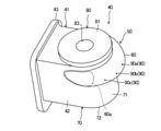
油分離器(40)は、吐出カバー(41)と、流入管(50)と、分離器本体(70)と、内部材(80)とを備えている。吐出カバー(41)は、上述したケーシング(11)の一部を兼用している。流入管(50)は、高圧空間(H)の高圧冷媒を分離器本体(70)に導入する。分離器本体(70)は、有底筒状に形成される。分離器本体(70)の周壁は、外筒(71)を構成している。内部材(80)は、分離器本体(70)の上部に取り付けられる。内部材(80)は、分離器本体(70)の上側を閉塞する天板(81)と、分離器本体(70)の内部に配置される内筒(82)とを有している。 The oil separator (40) includes a discharge cover (41), an inflow pipe (50), a separator main body (70), and an inner member (80). The discharge cover (41) also serves as a part of the casing (11) described above. The inflow pipe (50) introduces the high-pressure refrigerant in the high-pressure space (H) into the separator main body (70). The separator body (70) is formed in the shape of a bottomed cylinder. The peripheral wall of the separator body (70) constitutes the outer cylinder (71). The inner member (80) is attached to the upper part of the separator body (70). The inner member (80) has a top plate (81) that closes the upper side of the separator main body (70), and an inner cylinder (82) that is arranged inside the separator main body (70).
〈吐出カバー〉
図2及び図3に示すように、吐出カバー(41)は、吐出カバー本体(42)と、フランジ(43)とを備えている。吐出カバー本体(42)は、角形筒状に形成される。吐出カバー本体(42)には、ケーシング本体(12)を向く側面にカバー開口(44)が形成される。吐出カバー本体(42)の内部には、油を分離するための第1内部空間(45)が形成される。第1内部空間(45)は、高圧空間(H)の一部を構成している。つまり、第1内部空間(45)は、第1油溜まり(18)の一部を構成している。
<Discharge cover>
As shown in FIGS. 2 and 3, the discharge cover (41) includes a discharge cover main body (42) and a flange (43). The discharge cover body (42) is formed in a square cylinder shape. The discharge cover body (42) is formed with a cover opening (44) on the side surface facing the casing body (12). A first internal space (45) for separating oil is formed inside the discharge cover main body (42). The first internal space (45) constitutes a part of the high pressure space (H). That is, the first internal space (45) constitutes a part of the first oil sump (18).
フランジ(43)は、カバー開口(44)の外縁から径方向外方へ張り出している。フランジ(43)は、矩形枠状に形成される。フランジ(43)は、締結部材(図示省略)を介してケーシング本体(12)に連結される。これにより、ケーシング本体(12)が吐出カバー(41)によって閉塞され、一体的なケーシング(11)が構成される。 The flange (43) projects radially outward from the outer edge of the cover opening (44). The flange (43) is formed in a rectangular frame shape. The flange (43) is connected to the casing body (12) via a fastening member (not shown). As a result, the casing main body (12) is closed by the discharge cover (41), and an integrated casing (11) is configured.
〈流入管〉
流入管(50)は、分離器本体(70)の上部に設けられる。より厳密には、流入管(50)の高さ位置は、内筒(82)の下端よりも高い(図4を参照)。流入管(50)は、直線部(51)と湾曲部(60)とを含んでいる。直線部(51)は、流入管(50)の上流側に形成され、湾曲部(60)は流入管(50)の下流側に形成される。
<Inflow pipe>
The inflow pipe (50) is provided on the upper part of the separator main body (70). More precisely, the height position of the inflow pipe (50) is higher than the lower end of the inner cylinder (82) (see FIG. 4). The inflow pipe (50) includes a straight portion (51) and a curved portion (60). The straight portion (51) is formed on the upstream side of the inflow pipe (50), and the curved portion (60) is formed on the downstream side of the inflow pipe (50).
図3に示すように、直線部(51)は、吐出カバー本体(42)の内部に位置している。直線部(51)は、ケーシング(11)の軸心に沿うように水平に延びている。直線部(51)の流入端(即ち、流入管(50)の流入口(51a))は高圧空間(H)に面している。流入口(51a)は、フランジ(43)の端面と略面一に形成される。 As shown in FIG. 3, the straight portion (51) is located inside the discharge cover main body (42). The straight portion (51) extends horizontally along the axis of the casing (11). The inflow end of the straight portion (51) (that is, the inflow port (51a) of the inflow pipe (50)) faces the high pressure space (H). The inflow port (51a) is formed substantially flush with the end face of the flange (43).
湾曲部(60)は、流入管(50)に流入した冷媒中の油を遠心力によって分離する機能を有する。本実施形態の湾曲部(60)は、分離器本体(70)の外部に形成される。湾曲部(60)の始端は、直線部(51)と連続している。湾曲部(60)は、分離器本体(70)の軸周り方向に湾曲している。より厳密には、湾曲部(60)は、その上流部から下流部に向かって、分離器本体(70)の内部の旋回流の回転方向と同じ方向に湾曲している。湾曲部(60)は、分離器本体(70)の外筒(71)に沿うように、あるいは該外筒(71)を囲むように湾曲している。湾曲部(60)は、分離器本体(70)の外筒(71)を囲むように湾曲している。 The curved portion (60) has a function of separating the oil in the refrigerant flowing into the inflow pipe (50) by centrifugal force. The curved portion (60) of the present embodiment is formed on the outside of the separator main body (70). The starting end of the curved portion (60) is continuous with the straight portion (51). The curved portion (60) is curved in the axial direction of the separator main body (70). More precisely, the curved portion (60) is curved from the upstream portion to the downstream portion in the same direction as the rotation direction of the swirling flow inside the separator main body (70). The curved portion (60) is curved so as to be along the outer cylinder (71) of the separator main body (70) or to surround the outer cylinder (71). The curved portion (60) is curved so as to surround the outer cylinder (71) of the separator main body (70).
図5に示すように、湾曲部(60)の流出端(60a)は、分離器本体(70)の第2内部空間(73)に開口している。湾曲部(60)の流出端(60a)は、外筒(71)の内周面の接線に沿った方向を向いている。 As shown in FIG. 5, the outflow end (60a) of the curved portion (60) is open to the second internal space (73) of the separator main body (70). The outflow end (60a) of the curved portion (60) faces the direction along the tangent to the inner peripheral surface of the outer cylinder (71).
図5に示すように、流入管(50)の流入口(51a)の軸線(L1)は、分離器本体(70)の外筒(71)の外周面の接線(L2)よりも、分離器本体(70)の中心(P)に向かってオフセットしている。 As shown in FIG. 5, the axis (L1) of the inlet (51a) of the inflow pipe (50) is more than the tangent (L2) of the outer peripheral surface of the outer cylinder (71) of the separator body (70). It is offset toward the center (P) of the main body (70).
〈分離器本体〉
分離器本体(70)は、冷媒の旋回流により生じる遠心力を利用して、冷媒中の油を分離する。分離器本体(70)は、上側が開放する縦長の有底円筒状の容器である。分離器本体(70)は、上述した外筒(71)と、該外筒(71)の下側を閉塞する円板状の底板(72)(底部)とを有する。分離器本体(70)の内部には、第2内部空間(73)が形成される。第2内部空間(73)の下部には、分離された油が貯留される第2油溜まり(74)が形成される。
<Separator body>
The separator main body (70) separates the oil in the refrigerant by utilizing the centrifugal force generated by the swirling flow of the refrigerant. The separator body (70) is a vertically long bottomed cylindrical container with an open upper side. The separator main body (70) has the above-mentioned outer cylinder (71) and a disk-shaped bottom plate (72) (bottom) that closes the lower side of the outer cylinder (71). A second internal space (73) is formed inside the separator main body (70). At the lower part of the second internal space (73), a second oil sump (74) in which the separated oil is stored is formed.
外筒(71)の下端部には、油排出口(75)が形成される。油排出口(75)は、第2内部空間(73)(第2油溜まり(74))と、第1内部空間(第1油溜まり(18))とを連通させる。これにより、第2油溜まり(74)の油を、油排出口(75)を介して第1油溜まり(18)へ送ることができる。 An oil discharge port (75) is formed at the lower end of the outer cylinder (71). The oil discharge port (75) communicates the second internal space (73) (second oil sump (74)) with the first internal space (first oil sump (18)). As a result, the oil in the second oil sump (74) can be sent to the first oil sump (18) via the oil discharge port (75).
〈内部材〉
内部材(80)は、上述した天板(81)及び内筒(82)を有している。
<Inner member>
The inner member (80) has the above-mentioned top plate (81) and inner cylinder (82).
天板(81)は、円形開口(83)が板厚方向(鉛直方向)に貫通する円板状に形成される。天板(81)の外径は、分離器本体(70)の内径よりも大きい。天板(81)の外周縁部は、分離器本体(70)の上端に固定される。天板(81)の円形開口(83)には、冷媒回路の冷媒配管(吐出管)が接続される。 The top plate (81) is formed in the shape of a disk through which the circular opening (83) penetrates in the plate thickness direction (vertical direction). The outer diameter of the top plate (81) is larger than the inner diameter of the separator body (70). The outer peripheral edge of the top plate (81) is fixed to the upper end of the separator main body (70). The refrigerant pipe (discharge pipe) of the refrigerant circuit is connected to the circular opening (83) of the top plate (81).
内筒(82)は、天板(81)の円形開口(83)の内縁から下方に延びる円筒状に形成される。内筒(82)は、外筒(71)と同軸上に配置される。これにより、内筒(82)と外筒(71)との間には、冷媒が軸周り(図5の矢印Xで示す方向)に旋回する円筒状の空間が形成される。内筒(82)の内部には、冷媒が上方に流れる内部通路(84)が形成される。内部通路(84)の流入端(下端)には、第2内部空間(73)に連通する流入口(内筒流入口(85))が形成される。内部通路(84)の流出端(上端)は、円形開口(83)に連通する。 The inner cylinder (82) is formed in a cylindrical shape extending downward from the inner edge of the circular opening (83) of the top plate (81). The inner cylinder (82) is arranged coaxially with the outer cylinder (71). As a result, a cylindrical space is formed between the inner cylinder (82) and the outer cylinder (71) in which the refrigerant swirls around the axis (direction indicated by the arrow X in FIG. 5). Inside the inner cylinder (82), an internal passage (84) through which the refrigerant flows upward is formed. At the inflow end (lower end) of the internal passage (84), an inflow port (inner cylinder inflow port (85)) communicating with the second internal space (73) is formed. The outflow end (upper end) of the internal passage (84) communicates with the circular opening (83).
〈湾曲部の詳細〉
流入管(50)の湾曲部(60)の詳細な構成について説明する。
<Details of curved part>
The detailed configuration of the curved portion (60) of the inflow pipe (50) will be described.
図5及び図6に示すように、湾曲部(60)は、第1壁(61)と第2壁(62)とを有する。第1壁(61)が内側寄り(分離器本体(70)寄り)に位置し、第2壁(62)が外側寄りに位置している。 As shown in FIGS. 5 and 6, the curved portion (60) has a first wall (61) and a second wall (62). The first wall (61) is located closer to the inside (closer to the separator body (70)), and the second wall (62) is located closer to the outside.
第1壁(61)は、分離器本体(70)の外筒(71)と略面一に形成される。第1壁(61)、及びその内面(61a)は、流入管(50)の軸直角断面視において、上下に延びる平坦形状である。第1壁(61)は、分離器本体(70)の軸直角断面視において、略円弧状である。第1壁(61)は、分離器本体(70)の軸心を基準とした場合に、約180°以上の範囲に亘って形成される。 The first wall (61) is formed substantially flush with the outer cylinder (71) of the separator main body (70). The first wall (61) and its inner surface (61a) have a flat shape extending vertically in a cross-sectional view perpendicular to the axis of the inflow pipe (50). The first wall (61) has a substantially arc shape in a cross-sectional view perpendicular to the axis of the separator main body (70). The first wall (61) is formed over a range of about 180 ° or more with respect to the axis of the separator main body (70).
第1壁(61)は、外筒(71)の一部として兼用されている。つまり、分離器本体(70)の周壁(外筒(71))と湾曲部(60)の第1壁(61)とが、共有部(C)を構成している。換言すると、第1壁(61)は、湾曲部(60)内の通路(63)と、分離器本体(70)の内部空間(第2内部空間(73))との間の隔壁を構成している。 The first wall (61) is also used as a part of the outer cylinder (71). That is, the peripheral wall (outer cylinder (71)) of the separator main body (70) and the first wall (61) of the curved portion (60) form the common portion (C). In other words, the first wall (61) constitutes a partition wall between the passage (63) in the curved portion (60) and the internal space (second internal space (73)) of the separator body (70). ing.
第2壁(62)は、外筒(71)ないし第1壁(61)から径方向外方へ膨出している。第2壁(62)は、流入管(50)の軸直角断面視において、外筒(71)側に開口するU字形状である。第2壁(62)は、分離器本体(70)の軸直角断面視において、略円弧状である。第2壁(62)は、分離器本体(70)の軸心を基準とした場合に、約180°以上の範囲に亘って形成される。 The second wall (62) bulges outward in the radial direction from the outer cylinder (71) to the first wall (61). The second wall (62) has a U-shape that opens toward the outer cylinder (71) in a cross-sectional view perpendicular to the axis of the inflow pipe (50). The second wall (62) has a substantially arc shape in a cross-sectional view perpendicular to the axis of the separator main body (70). The second wall (62) is formed over a range of about 180 ° or more with respect to the axis of the separator main body (70).
第2壁(62)は、分離器本体(70)と共有されない非共有部である。第2壁(62)は、分離器本体(70)の外部に位置している。従って、第2壁(62)は、外部(大気温度雰囲気)に露出される露出部を構成している。 The second wall (62) is a non-shared part that is not shared with the separator body (70). The second wall (62) is located outside the separator body (70). Therefore, the second wall (62) constitutes an exposed portion exposed to the outside (atmospheric temperature atmosphere).
図5に示すように、第2壁(62)の内面と外筒(71)の内面とは、滑らかに連続している。つまり、分離器本体(70)の軸直角な断面形状において、第2壁(62)と外筒(71)とは、滑らかに連続する渦巻き状の内壁を構成している。この渦巻き状の内壁は、その外端から内端へ向かって、冷媒の旋回流と同じ方向に巻かれている。 As shown in FIG. 5, the inner surface of the second wall (62) and the inner surface of the outer cylinder (71) are smoothly continuous. That is, in the cross-sectional shape perpendicular to the axis of the separator main body (70), the second wall (62) and the outer cylinder (71) form a smoothly continuous spiral inner wall. The spiral inner wall is wound in the same direction as the swirling flow of the refrigerant from the outer end to the inner end.
〈油抜き穴〉
図7に示すように、湾曲部(60)には、その内部の通路(63)に溜まった油を湾曲部(60)の外部へ排出するための油抜き穴(90)が形成される。油抜き穴(90)の流路断面の形状は、例えば円形に形成される。油抜き穴(90)は、湾曲部(60)の外周側部分(64)に形成される。ここで、外周側部分(64)は、湾曲部(60)の管壁のうち分離器本体(70)の軸心を向く部分である。また、同図に示すように、油抜き穴(90)は、湾曲部(60)の下側部分(65)に形成される。ここで、下側部分(65)は、湾曲部(60)の管壁のうち、湾曲部(60)内の通路(63)の軸心(上下方向の中間の高さ位置)よりも低い部分である。油抜き穴(90)は、湾曲部(60)のうち下流端寄りに設けられる。油抜き穴(90)は、湾曲部(60)の内周面の曲率中心を向くように法線方向に開口している。本実施形態の油抜き穴(90)は1つであるが2つ以上であってもよい。
<Oil drain hole>
As shown in FIG. 7, the curved portion (60) is formed with an oil drain hole (90) for discharging the oil accumulated in the passage (63) inside the curved portion (60) to the outside of the curved portion (60). The shape of the cross section of the flow path of the oil drain hole (90) is formed, for example, in a circular shape. The oil drain hole (90) is formed in the outer peripheral side portion (64) of the curved portion (60). Here, the outer peripheral side portion (64) is a portion of the pipe wall of the curved portion (60) facing the axis of the separator main body (70). Further, as shown in the figure, the oil drain hole (90) is formed in the lower portion (65) of the curved portion (60). Here, the lower portion (65) is a portion of the pipe wall of the curved portion (60) that is lower than the axis (the middle height position in the vertical direction) of the passage (63) in the curved portion (60). Is. The oil drain hole (90) is provided near the downstream end of the curved portion (60). The oil drain hole (90) is opened in the normal direction so as to face the center of curvature of the inner peripheral surface of the curved portion (60). The oil drain hole (90) of the present embodiment is one, but may be two or more.
〈連通部材〉
図2及び図7に示すように、通路部材(91)は、油抜き穴(90)に対応する位置に設けられる。通路部材(91)は、縦長の直方体、ないし平板状に形成される。通路部材(91)の内部には、油抜き穴(90)と繋がる油通路(92)が形成される。油通路(92)は、湾曲部(60)の油抜き穴(90)と、分離器本体(70)の第2内部空間(第2油溜まり(74))とを連通させる。油通路(92)は、縦長の縦通路(92a)と、縦通路(92a)の下端に接続する横長の横通路(92b)と、横通路(92b)の径方向内端に接続する流出通路(92c)とを含んでいる。図8に示すように、油通路(92)の流出開口(93)は、分離器本体(70)の外筒(71)に形成される。より具体的には、油通路(92)の流出開口(93)は、内筒流入口(85)より下側で、且つ該内筒流入口(85)よりも外周側に位置している。油通路(92)の流出開口(93)の軸線(L3)は、外筒(71)の内周面(71a)の接線(L4)に沿った方向を向いている。つまり、本実施形態では、流出開口(93)の軸線(L3)が、外筒(71)の内周面(71a)の接線(L4)(厳密には、流出開口(93)が形成される箇所の接線)と概ね一致している。
<Communication member>
As shown in FIGS. 2 and 7, the passage member (91) is provided at a position corresponding to the oil drain hole (90). The passage member (91) is formed in a vertically long rectangular parallelepiped or flat plate shape. An oil passage (92) connected to the oil drain hole (90) is formed inside the passage member (91). The oil passage (92) communicates the oil drain hole (90) of the curved portion (60) with the second internal space (second oil sump (74)) of the separator main body (70). The oil passage (92) is a vertically long vertical passage (92a), a horizontally long horizontal passage (92b) connected to the lower end of the vertical passage (92a), and an outflow passage connected to the radial inner end of the horizontal passage (92b). (92c) and is included. As shown in FIG. 8, the outflow opening (93) of the oil passage (92) is formed in the outer cylinder (71) of the separator main body (70). More specifically, the outflow opening (93) of the oil passage (92) is located below the inner cylinder inflow port (85) and on the outer peripheral side of the inner cylinder inflow port (85). The axis (L3) of the outflow opening (93) of the oil passage (92) points in the direction along the tangent line (L4) of the inner peripheral surface (71a) of the outer cylinder (71). That is, in the present embodiment, the axis (L3) of the outflow opening (93) is formed with the tangent (L4) (strictly speaking, the outflow opening (93)) of the inner peripheral surface (71a) of the outer cylinder (71). It is almost the same as the tangent line of the place).
〈油分離器の一体構造〉
油分離器(40)は、吐出カバー(41)、流入管(50)、分離器本体(70)、及び通路部材(91)が、鋳造によって一体成型される。つまり、吐出カバー(41)、流入管(50)、分離器本体(70)、及び通路部材(91)は、鋳物からなる一体構造の第1ユニットを構成している。一方、内部材(80)は、第1ユニットと別部材の第2ユニットで構成される。
<Integrated structure of oil separator>
In the oil separator (40), the discharge cover (41), the inflow pipe (50), the separator main body (70), and the passage member (91) are integrally molded by casting. That is, the discharge cover (41), the inflow pipe (50), the separator main body (70), and the passage member (91) constitute the first unit having an integral structure made of a casting. On the other hand, the inner member (80) is composed of a first unit and a second unit of another member.
-油分離器の動作-
図1に示すように、圧縮機(10)の運転時には、圧縮室(35)で圧縮された後の冷媒が、高圧空間(H)から流入管(50)に流入する。この冷媒は、直線部(51)を通過した後、湾曲部(60)を流れる。湾曲部(60)では、冷媒が湾曲部(60)に沿って旋回する。これにより、冷媒中の小さな油滴が遠心力によって分離される。
-Operation of oil separator-
As shown in FIG. 1, when the compressor (10) is in operation, the refrigerant compressed in the compression chamber (35) flows from the high pressure space (H) into the inflow pipe (50). This refrigerant passes through the straight portion (51) and then flows through the curved portion (60). At the bend (60), the refrigerant swirls along the bend (60). As a result, small oil droplets in the refrigerant are separated by centrifugal force.
ここで、図4及び図6に示すように、湾曲部(60)では、第1壁(61)が分離器本体(70)の第2内部空間(73)に面するのに対し、第2壁(62)は分離器本体(70)の外部に露出している。また、第2内部空間(73)には高温の冷媒が流れるのに対し、分離器本体(70)の外部は大気温度雰囲気である。このため、第2壁(62)は第1壁(61)よりも低い温度になる。このため、比較的高温の第1壁(61)の近傍の油滴は流動し易くなり、遠心力によって第2壁(62)側に移動し易くなる。一方、比較的低温の第2壁(62)の近傍の油は、冷却されて流動しにくくなる。このため、湾曲部(60)では、第2壁(62)ないし外周側部分(64)において、油が捕集され易くなり、捕集された油滴のサイズも大きくなり易い。 Here, as shown in FIGS. 4 and 6, in the curved portion (60), the first wall (61) faces the second internal space (73) of the separator main body (70), whereas the second wall (61) faces the second internal space (73). The wall (62) is exposed to the outside of the separator body (70). Further, while the high temperature refrigerant flows in the second internal space (73), the outside of the separator main body (70) has an atmospheric temperature atmosphere. Therefore, the temperature of the second wall (62) is lower than that of the first wall (61). Therefore, the oil droplets in the vicinity of the first wall (61) having a relatively high temperature are likely to flow, and are easily moved to the second wall (62) side by the centrifugal force. On the other hand, the oil in the vicinity of the second wall (62), which has a relatively low temperature, is cooled and becomes difficult to flow. Therefore, in the curved portion (60), oil is likely to be collected in the second wall (62) or the outer peripheral side portion (64), and the size of the collected oil droplets is also likely to be large.
このようにして湾曲部(60)で油滴のサイズが大きくなった油は、冷媒とともに分離器本体(70)に流入する。分離器本体(70)では、第2内部空間(73)において冷媒が旋回する。この結果、冷媒中の油滴が遠心力によって更に分離される。ここで、冷媒中の油滴は、上述した湾曲部(60)を通過する際にサイズが大きくなっている。この結果、油滴に作用する遠心力が増大し、油の分離効率が向上する。 The oil whose oil droplet size has increased at the curved portion (60) flows into the separator main body (70) together with the refrigerant. In the separator main body (70), the refrigerant swirls in the second internal space (73). As a result, the oil droplets in the refrigerant are further separated by the centrifugal force. Here, the oil droplets in the refrigerant have an increased size as they pass through the curved portion (60) described above. As a result, the centrifugal force acting on the oil droplets increases, and the oil separation efficiency is improved.
第2内部空間(73)で分離された油は、第2油溜まり(74)に貯留される。油が分離された後の冷媒は、内部通路(84)を上方へ流れ、吐出管を介して冷媒回路へ送られる。 The oil separated in the second internal space (73) is stored in the second oil sump (74). After the oil is separated, the refrigerant flows upward through the internal passage (84) and is sent to the refrigerant circuit via the discharge pipe.
上述した湾曲部(60)には、油抜き穴(90)が形成されている。このため、湾曲部(60)で分離された油の一部を油抜き穴(90)及び油通路(92)を介して直接的に第2油溜まり(74)に送ることがでる。 An oil drain hole (90) is formed in the curved portion (60) described above. Therefore, a part of the oil separated by the curved portion (60) can be directly sent to the second oil sump (74) through the oil drain hole (90) and the oil passage (92).
油抜き穴(90)は、湾曲部(60)の外周側部分(64)に形成される。ここで、外周側部分(64)には、遠心力によって移動した油滴が溜まり易い。このため、外周側部分(64)の内壁に捕集した油を油抜き穴(90)に導き易くなる。 The oil drain hole (90) is formed in the outer peripheral side portion (64) of the curved portion (60). Here, oil droplets moved by centrifugal force tend to collect in the outer peripheral side portion (64). Therefore, it becomes easy to guide the oil collected on the inner wall of the outer peripheral side portion (64) to the oil drain hole (90).
油抜き穴(90)は、湾曲部(60)の下側部分(65)に形成される。このため、自重により下側部分(65)の内壁に溜まった油を油抜き穴(90)に導き易くなる。 The oil drain hole (90) is formed in the lower portion (65) of the curved portion (60). Therefore, it becomes easy to guide the oil accumulated in the inner wall of the lower portion (65) to the oil drain hole (90) due to its own weight.
油通路(92)の流出開口(93)は、外筒(71)に形成される。このため、この流出開口(93)と、内部通路(84)の流入端との距離を十分に確保できる。また、図8に示すように、流出開口(93)(軸線(L3))は、外筒(71)の接線(L4)方向を向くように開口するため、流出開口(93)から流出した油は、外筒(71)の内周面に沿うように、第2内部空間(73)へ流入する。この結果、油通路(92)から第2内部空間(73)に流入した油が、内部通路(84)へ向かう冷媒の流れにのって、該冷媒とともに吐出管へ送られることを回避できる。 The outflow opening (93) of the oil passage (92) is formed in the outer cylinder (71). Therefore, a sufficient distance between the outflow opening (93) and the inflow end of the internal passage (84) can be sufficiently secured. Further, as shown in FIG. 8, since the outflow opening (93) (axis line (L3)) opens so as to face the tangent line (L4) direction of the outer cylinder (71), the oil spilled from the outflow opening (93). Flows into the second internal space (73) along the inner peripheral surface of the outer cylinder (71). As a result, it is possible to prevent the oil flowing from the oil passage (92) into the second internal space (73) from being sent to the discharge pipe together with the refrigerant along the flow of the refrigerant toward the internal passage (84).
第2油溜まり(74)の油は、油排出口(75)を介して第1油溜まり(18)へ送られる。第1油溜まり(18)の油は、油導入路(17)を経由して軸受け室(26)に送られる。この軸受け室(26)の油により、第2軸受け(25)の摺動部の潤滑が行われる。なお、軸受け室(26)の油は、所定の通路(図示省略)を経由して、圧縮機構(30)や第1軸受け(24)の摺動部にも供給される。 The oil in the second oil sump (74) is sent to the first oil sump (18) through the oil discharge port (75). The oil in the first oil sump (18) is sent to the bearing chamber (26) via the oil introduction path (17). The oil in the bearing chamber (26) lubricates the sliding portion of the second bearing (25). The oil in the bearing chamber (26) is also supplied to the sliding portion of the compression mechanism (30) and the first bearing (24) via a predetermined passage (not shown).
-実施形態の作用/効果-
本形態では、湾曲部(60)に油抜き穴(90)を形成している。これにより、湾曲部(60)で分離した油が冷媒の流れの影響を受けて再飛散することを抑制できる。
-Action / effect of the embodiment-
In this embodiment, an oil drain hole (90) is formed in the curved portion (60). As a result, it is possible to prevent the oil separated at the curved portion (60) from being re-scattered under the influence of the flow of the refrigerant.
具体的には、圧縮機(10)は、電動機(20)の回転数、ひいては冷媒の循環量が調節可能である。このため、例えば冷媒の循環量を増大変化させると、湾曲部(60)を流れる冷媒の流速も増大する。この際、湾曲部(60)の内壁に付着した油は、冷媒によって吹き飛ばされ、細かい油滴が再飛散してしまう可能性がある。また、湾曲部(60)で分離した油が冷媒とともに分離器本体(70)へ流入する際にも、この油が冷媒によって吹き飛ばされ、油滴が再飛散してしまう可能性がある。 Specifically, the compressor (10) can adjust the rotation speed of the electric motor (20) and the circulation amount of the refrigerant. Therefore, for example, when the circulation amount of the refrigerant is increased and changed, the flow velocity of the refrigerant flowing through the curved portion (60) also increases. At this time, the oil adhering to the inner wall of the curved portion (60) may be blown off by the refrigerant, and fine oil droplets may be scattered again. Further, when the oil separated at the curved portion (60) flows into the separator main body (70) together with the refrigerant, the oil may be blown off by the refrigerant and the oil droplets may be scattered again.
これに対し、本形態では、湾曲部(60)で分離した油を、油抜き穴(90)を介して湾曲部(60)の外部へ排出できる。このため、上述のような油の再飛散を回避でき、油分離効率を向上できる。 On the other hand, in this embodiment, the oil separated by the curved portion (60) can be discharged to the outside of the curved portion (60) through the oil drain hole (90). Therefore, the re-scattering of the oil as described above can be avoided, and the oil separation efficiency can be improved.
本形態では、油抜き穴(90)が湾曲部(60)の外周側部分(64)に配置される。湾曲部(60)では、遠心力により分離された油が、外周側部分(64)の内壁に付着し易い。このため、外周側部分(64)に油抜き穴(90)を配置することで、分離後の油が油抜き穴(90)に流入し易くなる。 In this embodiment, the oil drain hole (90) is arranged on the outer peripheral side portion (64) of the curved portion (60). In the curved portion (60), the oil separated by the centrifugal force easily adheres to the inner wall of the outer peripheral side portion (64). Therefore, by arranging the oil drain hole (90) in the outer peripheral side portion (64), the separated oil can easily flow into the oil drain hole (90).
本形態では、油抜き穴(90)が湾曲部(60)の下側部分(65)に配置される。湾曲部(60)では、油の自重により、この油が下側部分(65)の内壁に付着し易い。このため、下側部分(65)に油抜き穴(90)を配置することで、分離後の油が油抜き穴(90)に流入し易くなる。 In this embodiment, the oil drain hole (90) is arranged in the lower portion (65) of the curved portion (60). At the curved portion (60), the oil tends to adhere to the inner wall of the lower portion (65) due to the weight of the oil itself. Therefore, by arranging the oil drain hole (90) in the lower portion (65), the separated oil can easily flow into the oil drain hole (90).
本形態では、油抜き穴(90)と、分離器本体(70)の第2油溜まり(74)とを連通させる油通路(92)を備えている。これにより、湾曲部(60)で分離した油を、再飛散することなしに第2油溜まり(74)に回収できる。加えて、油の遠心力を利用して、湾曲部(60)の油を第2油溜まり(74)へ搬送できる。加えて、油抜き穴(90)と第2油溜まり(74)との距離は比較的短いため、湾曲部(60)の油を確実に第2油溜まり(74)に送ることができる。加えて、湾曲部(60)は第2油溜まり(74)よりも高い位置にあるため、油の自重を利用して、湾曲部(60)の油を第2油溜まり(74)へ搬送できる。 In this embodiment, an oil passage (92) for communicating the oil drain hole (90) and the second oil sump (74) of the separator main body (70) is provided. As a result, the oil separated at the curved portion (60) can be recovered in the second oil sump (74) without re-scattering. In addition, the centrifugal force of the oil can be used to convey the oil in the curved portion (60) to the second oil sump (74). In addition, since the distance between the oil drain hole (90) and the second oil sump (74) is relatively short, the oil in the curved portion (60) can be reliably sent to the second oil sump (74). In addition, since the curved portion (60) is located higher than the second oil sump (74), the oil of the curved portion (60) can be transported to the second oil sump (74) by utilizing the weight of the oil itself. ..
本形態では、油通路(92)の流出開口(93)が、内筒流入口(85)より下側で、且つ該流入口(51a)よりも外周側に位置している。加えて、油通路(92)の流出開口(93)は、外筒(71)に形成されている。これらの構成により、油通路(92)の流出開口(93)と、内筒流入口(85)との距離を離すことができる。従って、油通路(92)の流出開口(93)を流出した油が、内筒流入口(85)に流入する冷媒の流れの影響により、再飛散したり、内筒流入口(85)に流入したりすることを回避できる。 In this embodiment, the outflow opening (93) of the oil passage (92) is located below the inner cylinder inflow port (85) and on the outer peripheral side of the inflow port (51a). In addition, the outflow opening (93) of the oil passage (92) is formed in the outer cylinder (71). With these configurations, the distance between the outflow opening (93) of the oil passage (92) and the inner cylinder inflow port (85) can be separated. Therefore, the oil that has flowed out of the outflow opening (93) of the oil passage (92) may re-scatter or flow into the inner cylinder inflow port (85) due to the influence of the flow of the refrigerant flowing into the inner cylinder inflow port (85). You can avoid doing it.
本形態では、油通路(92)の流出開口(93)は、分離器本体(70)の内周面(71a)の接線に沿った方向に開口している。このため、油通路(92)の流出開口(93)を流出した油が、内筒流入口(85)に流入する冷媒の流れの影響により、再飛散したり、内筒流入口(85)に流入したりすることを一層確実に回避できる。 In this embodiment, the outflow opening (93) of the oil passage (92) opens in the direction along the tangent line of the inner peripheral surface (71a) of the separator main body (70). Therefore, the oil that has flowed out of the outflow opening (93) of the oil passage (92) may re-scatter or reach the inner cylinder inflow port (85) due to the influence of the flow of the refrigerant flowing into the inner cylinder inflow port (85). It is possible to avoid inflow more reliably.
本形態では、油抜き穴(90)に流入した油が、第2油溜まり(74)、第1油溜まり(18)、油導入路(17)、軸受け室(26)を順に流れ、軸受け(24,25)や圧縮機構(30)へ供給される。このため、湾曲部(60)で分離した油をこれらの摺動部の潤滑に利用できる。 In this embodiment, the oil flowing into the oil drain hole (90) flows through the second oil sump (74), the first oil sump (18), the oil introduction path (17), and the bearing chamber (26) in this order, and the bearing ( It is supplied to 24,25) and the compression mechanism (30). Therefore, the oil separated at the curved portion (60) can be used for lubrication of these sliding portions.
《実施形態の変形例》
上記実施形態については、次のような変形例の構成としてもよい。
<< Modification of Embodiment >>
The above embodiment may be configured as a modified example as follows.
〈変形例1〉
図9に示す変形例1は、湾曲部(60)に複数(本例では3つ)の油抜き穴(90)が形成される。これらの油抜き穴(90)は、冷媒の流れ方向に配列される。より詳細に、これらの油抜き穴(90)は、上流側から下流側に向かって順に、第1油抜き穴(90a)、第2油抜き穴(90b)、及び第3油抜き穴(90c)で構成される。変形例1の湾曲部(60)では、各油抜き穴(90)の高さ位置(軸周りの角度位置)が互いに等しい。
<Modification example 1>
In the modified example 1 shown in FIG. 9, a plurality of (three in this example) oil drain holes (90) are formed in the curved portion (60). These oil vent holes (90) are arranged in the flow direction of the refrigerant. More specifically, these oil drain holes (90) are, in order from the upstream side to the downstream side, a first oil drain hole (90a), a second oil drain hole (90b), and a third oil drain hole (90c). ). In the curved portion (60) of the first modification, the height positions (angle positions around the axis) of the oil drain holes (90) are equal to each other.
変形例1では、複数の油抜き穴(90)の開口面積が、下流側に向かうにつれて小さい。具体的には、第1油抜き穴(90a)の開口面積をA1、第2油抜き穴(90b)の開口面積をA2、第3油抜き穴(90c)の開口面積をA3とすると、A1>A2>A3の関係を満たしている。なお、各油抜き穴(90)には、油通路(図示省略)が接続されている。 In the first modification, the opening area of the plurality of oil drain holes (90) becomes smaller toward the downstream side. Specifically, assuming that the opening area of the first oil drain hole (90a) is A1, the opening area of the second oil drain hole (90b) is A2, and the opening area of the third oil drain hole (90c) is A3, A1 The relationship of> A2> A3 is satisfied. An oil passage (not shown) is connected to each oil drain hole (90).
本形態では、湾曲部(60)での冷媒の流れ方向に複数の油抜き穴(90)を配置している。このため、湾曲部(60)から油抜き穴(90)へ導入する油の量を増大でき、油の再飛散を確実に抑制できる。 In this embodiment, a plurality of oil drain holes (90) are arranged in the flow direction of the refrigerant at the curved portion (60). Therefore, the amount of oil introduced from the curved portion (60) to the oil drain hole (90) can be increased, and the re-scattering of the oil can be reliably suppressed.
変形例1では、複数の油抜き穴(90)の開口面積が、下流側に向かうにつれて小さい。ここで、湾曲部(60)では、その上流側の方が下流側に比べて分離された油の量が多くなり易い。変形例1の油抜き穴(90)の開口面積は、分離される油の量、ないしサイズに対応している。このため、例えば第1油抜き穴(90a)では、比較的多くの油を確実に排出できる。また、例えば第3油抜き穴(90c)では、開口面積が過剰に大きくなることを回避できる。従って、例えば冷媒が第3油抜き穴(90c)を通じて湾曲部(60)の外部へ流出してしまうことを回避できる。 In the first modification, the opening area of the plurality of oil drain holes (90) becomes smaller toward the downstream side. Here, in the curved portion (60), the amount of separated oil tends to be larger on the upstream side than on the downstream side. The opening area of the oil drain hole (90) of the first modification corresponds to the amount or size of the oil to be separated. Therefore, for example, in the first oil drain hole (90a), a relatively large amount of oil can be reliably discharged. Further, for example, in the third oil drain hole (90c), it is possible to prevent the opening area from becoming excessively large. Therefore, for example, it is possible to prevent the refrigerant from flowing out to the outside of the curved portion (60) through the third oil drain hole (90c).
〈変形例2〉
図10に示す変形例2は、湾曲部(60)に複数の油抜き穴(90)を設けた構成において、各油抜き穴(90)の軸周りの角度位置が互いに異なっている。具体的の湾曲部(60)には、第1油抜き穴(90a)、第2油抜き穴(90b)、及び第3油抜き穴(90c)が冷媒の流れ方向に配列される。これらの油抜き穴(90)のサイズは、例えば同じに設定される。一方、これらの油抜き穴(90)は、湾曲部(60)の軸心(図10の点a)を基準とした周方向の角度位置が、軸直角断面視において互いにずれいている。なお、各油抜き穴(90)には、油通路(図示省略)が接続されている。
<Modification 2>
In the modified example 2 shown in FIG. 10, in a configuration in which a plurality of oil drain holes (90) are provided in the curved portion (60), the angular positions of the oil drain holes (90) around the axis are different from each other. In the specific curved portion (60), a first oil drain hole (90a), a second oil drain hole (90b), and a third oil drain hole (90c) are arranged in the flow direction of the refrigerant. The sizes of these drain holes (90) are set to be the same, for example. On the other hand, in these oil drain holes (90), the angular positions in the circumferential direction with respect to the axial center (point a in FIG. 10) of the curved portion (60) are deviated from each other in the cross-sectional view perpendicular to the axis. An oil passage (not shown) is connected to each oil drain hole (90).
本形態では、複数の油抜き穴(90)が、流入管(50)の軸周りの角度位置が互い異なる。湾曲部(60)では、分離された油が内壁の周方向に幅広に分布する場合もある。これに対し、このように複数の油抜き穴(90)の角度位置をずらすことで、このような油をいずれかの油抜き穴(90)内に捕捉できる。 In this embodiment, the plurality of oil drain holes (90) have different angular positions around the axis of the inflow pipe (50). In the curved portion (60), the separated oil may be widely distributed in the circumferential direction of the inner wall. On the other hand, by shifting the angular positions of the plurality of oil drain holes (90) in this way, such oil can be captured in any of the oil drain holes (90).
〈変形例3〉
図11に示す変形例3は、湾曲部(60)の油抜き穴(90)がスリット(95)で構成される。スリット(95)は、冷媒の流れ方向に延びている。スリット(95)は、湾曲部(60)の外周側部分(64)、且つ下側部分(65)に配置するのが好ましい。変形例3のスリット(95)は、下流側に向かうにつれて開口幅(湾曲部(60)の周方向の幅)が小さくなっている。なお、スリット(95)には、油通路(図示省略)が接続されている。
<Modification 3>
In the modified example 3 shown in FIG. 11, the oil drain hole (90) of the curved portion (60) is composed of a slit (95). The slit (95) extends in the direction of flow of the refrigerant. The slit (95) is preferably arranged on the outer peripheral side portion (64) and the lower portion (65) of the curved portion (60). The opening width (width in the circumferential direction of the curved portion (60)) of the slit (95) of the modified example 3 becomes smaller toward the downstream side. An oil passage (not shown) is connected to the slit (95).
この形態では、スリット(95)の開口幅が、下流側に向かうにつれて小さい。つまり、変形例3では、スリット(95)の開口幅は、分離される油の量、ないしサイズに対応している。このため、例えばスリット(95)の上流部分では、比較的多くの油を確実に排出できる。また、例えばスリット(95)の下流部分では、開口幅が過剰に大きくなることを回避できる。従って、例えば冷媒がスリット(95)の下流部分を通じて湾曲部(60)の外部へ流出してしまうこを回避できる。 In this form, the opening width of the slit (95) becomes smaller toward the downstream side. That is, in the third modification, the opening width of the slit (95) corresponds to the amount or size of the oil to be separated. Therefore, for example, in the upstream portion of the slit (95), a relatively large amount of oil can be reliably discharged. Further, for example, in the downstream portion of the slit (95), it is possible to prevent the opening width from becoming excessively large. Therefore, for example, it is possible to prevent the refrigerant from flowing out to the outside of the curved portion (60) through the downstream portion of the slit (95).
〈変形例4〉
図12に示す変形例4は、上記実施形態と第2壁(62)の形状が異なる。変形例4の第2壁(62)の内面(62a)は、軸直角断面視において、径方向外方へ向かうにつれて先細な形状をしている。具体的に、変形例4の湾曲部(60)は、多角形(本例では5角形)の断面形状を有する。第2壁(62)では、外側寄りの2つの面(62b,62b)の間隔が径方向外方に向かうにつれて狭くなっている。これにより、第2壁(62)では、径方向外方の先端に対応する部分に、油を捕捉する溝(67)が形成される。
<Modification example 4>
In the modified example 4 shown in FIG. 12, the shape of the second wall (62) is different from that of the above embodiment. The inner surface (62a) of the second wall (62) of the modified example 4 has a tapered shape as it goes outward in the radial direction in a cross-sectional view perpendicular to the axis. Specifically, the curved portion (60) of the modified example 4 has a polygonal (pentagonal in this example) cross-sectional shape. In the second wall (62), the distance between the two outer surfaces (62b, 62b) becomes narrower toward the outside in the radial direction. As a result, in the second wall (62), a groove (67) for catching oil is formed in a portion corresponding to the radial outer tip.
本形態では、油抜き穴(90)が、湾曲部(60)の内面(61a)の先端に対応する先端部(即ち、溝(67)の底部)に配置される。このため、溝(67)を流れる油を油抜き穴(90)に容易に導くことができる。 In this embodiment, the oil drain hole (90) is arranged at the tip corresponding to the tip of the inner surface (61a) of the curved portion (60) (that is, the bottom of the groove (67)). Therefore, the oil flowing through the groove (67) can be easily guided to the oil drain hole (90).
〈変形例5〉
図13に示す変形例5の湾曲部(60)は、径方向外方へ向かうにつれて先細な三角形の断面形状を有する。湾曲部(60)では、その径方向外方の先端に溝(67)が形成され、この溝(67)の底部に油抜き穴(90)が形成される。変形例5においても、変形例4と同様の作用・効果が得られる。
<Modification 5>
The curved portion (60) of the modified example 5 shown in FIG. 13 has a triangular cross-sectional shape that tapers toward the outside in the radial direction. In the curved portion (60), a groove (67) is formed at the tip outside the radial direction thereof, and an oil drain hole (90) is formed at the bottom of the groove (67). Also in the modified example 5, the same actions and effects as those of the modified example 4 can be obtained.
〈変形例6〉
図14に示す変形例6は、分離器本体(70)の内部に分離板(76)が設けられる。分離板(76)は、下方に向かって内径が小さくなる略円錐台の筒状に形成される。分離板(76)の上端は、外筒(71)に支持される。分離板(76)の下端には、円形の開口が形成される。分離板(76)は、第2油溜まり(74)の油が内筒(82)の内部へ流入してしまうことを抑制する。
<Modification 6>
In the modified example 6 shown in FIG. 14, a separation plate (76) is provided inside the separator main body (70). The separation plate (76) is formed in the shape of a substantially truncated cone whose inner diameter decreases downward. The upper end of the separating plate (76) is supported by the outer cylinder (71). A circular opening is formed at the lower end of the separating plate (76). The separation plate (76) prevents the oil in the second oil sump (74) from flowing into the inner cylinder (82).
本形態では、油通路(92)の流出開口(93)は、分離板(76)の下側に位置する。このため、油通路(92)の流出開口(93)を流出した油が、内筒流入口(85)に流入する冷媒の流れの影響により、再飛散したり、内筒流入口(85)に流入したりすることを、分離板(76)によって抑制できる。 In this embodiment, the outflow opening (93) of the oil passage (92) is located below the separation plate (76). Therefore, the oil that has flowed out of the outflow opening (93) of the oil passage (92) may re-scatter or reach the inner cylinder inflow port (85) due to the influence of the flow of the refrigerant flowing into the inner cylinder inflow port (85). The inflow can be suppressed by the separation plate (76).
〈変形例7〉
図15に示す変形例5は、流入管(50)と分離器本体(70)とが一体化されておらず、別部材で構成されている。流入管(50)の湾曲部(60)には、上記実施形態と同様、油抜き穴(90)が形成される。なお、油抜き穴(90)には、油通路(図示省略)が接続されている。
<Modification 7>
In the modified example 5 shown in FIG. 15, the inflow pipe (50) and the separator main body (70) are not integrated, but are composed of separate members. An oil drain hole (90) is formed in the curved portion (60) of the inflow pipe (50) as in the above embodiment. An oil passage (not shown) is connected to the oil drain hole (90).
〈変形例8〉
図16に示す変形例8では、油分離器(40)が圧縮機(10)のケーシング(11)の内部に収容される。油分離器(40)は、ケーシング(11)の吐出カバー(14)の内部に収容される。吐出カバー(14)は、油分離器(40)と別体に構成され、上述したケーシング本体(11)の高圧側の開口部を閉塞している。吐出カバー(14)の内部には、高圧冷媒で満たされる高圧空間(H)が形成される。吐出カバー(14)の下側には、油溜まり(14a)が形成される。
<Modification 8>
In the modified example 8 shown in FIG. 16, the oil separator (40) is housed inside the casing (11) of the compressor (10). The oil separator (40) is housed inside the discharge cover (14) of the casing (11). The discharge cover (14) is configured separately from the oil separator (40) and closes the opening on the high pressure side of the casing body (11) described above. A high-pressure space (H) filled with the high-pressure refrigerant is formed inside the discharge cover (14). An oil sump (14a) is formed on the lower side of the discharge cover (14).
油分離器(40)は、油溜まり(14a)の上側において、例えば支持部材(15)によって支持される。圧縮機構(30)で圧縮された高圧の冷媒は、上述した各形態と同様、流入管(50)の湾曲部(60)を流れた後、分離器本体(70)に流入する。分離器本体(70)の内部の流体は、吐出管(85)を介して冷媒回路へ送られる。 The oil separator (40) is supported above the oil sump (14a), for example by a support member (15). The high-pressure refrigerant compressed by the compression mechanism (30) flows through the curved portion (60) of the inflow pipe (50) and then flows into the separator main body (70), as in each of the above-described forms. The fluid inside the separator body (70) is sent to the refrigerant circuit via the discharge pipe (85).
変形例8では、上記実施形態と同様、湾曲部(60)に油抜き穴(90)が形成される。油抜き穴(90)は、湾曲部(60)の内部と、湾曲部(60)の外部とを直に連通させている。このため、湾曲部(60)の油抜き穴(90)を流出した油は、自重によって下方へ落ち、直接的に油溜まり(14a)に回収される。油溜まり(14a)の油は、上記実施形態と同様、所定の油導入路を経由して、圧縮機構(30)や軸受け(24,25)の潤滑に利用される。なお、湾曲部(60)の油抜き穴(90)は、上述した各形態の構成のいずれを採用してもよい。 In the modified example 8, the oil drain hole (90) is formed in the curved portion (60) as in the above embodiment. The oil drain hole (90) directly communicates the inside of the curved portion (60) with the outside of the curved portion (60). Therefore, the oil that has flowed out of the oil drain hole (90) of the curved portion (60) falls downward due to its own weight and is directly collected in the oil sump (14a). The oil in the oil sump (14a) is used for lubrication of the compression mechanism (30) and the bearings (24, 25) via a predetermined oil introduction path as in the above embodiment. The oil drain hole (90) of the curved portion (60) may have any of the above-described configurations.
《その他の実施形態》
図17に示すように、油通路(92)の流出開口(93)の軸線(L3)は、外筒(71)の内周面(71a)の接線(L4)と一致してなくてもよい。具体的には、流出開口(93)は、接線(L4)に沿う方向に開口する一方、軸線(L3)が接線(L4)よりも中心(P)側にオフセットしていてもよい。また、流出開口(93)は、中心(P)を向くように法線方向に向かって開口していてもよい。
<< Other Embodiments >>
As shown in FIG. 17, the axis (L3) of the outflow opening (93) of the oil passage (92) does not have to coincide with the tangent (L4) of the inner peripheral surface (71a) of the outer cylinder (71). .. Specifically, the outflow opening (93) may open in the direction along the tangent line (L4), while the axis line (L3) may be offset toward the center (P) side of the tangent line (L4). Further, the outflow opening (93) may be opened toward the normal direction so as to face the center (P).
油分離器(40)は、分離器本体(70)の内部で遠心力を利用して油を分離する遠心式であれば、如何なる構成であってもよく、内筒(82)を有さなくてもよい。 The oil separator (40) may have any configuration as long as it is a centrifugal type that separates oil by using centrifugal force inside the separator main body (70), and does not have an inner cylinder (82). You may.
第2油溜まり(74)に回収した油を直接的に軸受け室(26)に送ってもよいし、軸受け室(26)を経由せずに、圧縮機構(30)などの摺動部へ供給してもよい。第2油溜まり(74)の油を圧縮室(35)の圧縮途中(中間圧部分)に戻してもよい。 The oil recovered in the second oil sump (74) may be sent directly to the bearing chamber (26), or may be supplied to a sliding portion such as a compression mechanism (30) without passing through the bearing chamber (26). You may. The oil in the second oil sump (74) may be returned to the middle of compression (intermediate pressure portion) in the compression chamber (35).
同様に、油抜き穴(90)から抜いた油を直接的に軸受け室(26)に送ってもよいし、軸受け室(26)を経由せずに、圧縮機構(30)などの摺動部へ供給してもよい。油抜き穴(90)から抜いた油を圧縮室(35)の圧縮途中(中間圧部分)に戻してもよい。 Similarly, the oil drained from the oil drain hole (90) may be sent directly to the bearing chamber (26), or a sliding portion such as a compression mechanism (30) without passing through the bearing chamber (26). May be supplied to. The oil drained from the oil drain hole (90) may be returned to the middle of compression (intermediate pressure portion) of the compression chamber (35).
圧縮機(10)は、2つのスクリューを有するツインスクリュー圧縮機であってもよいし、1つのゲートロータを有する1ゲート型のシングルスクリュー圧縮機であってもよい。 The compressor (10) may be a twin-screw compressor having two screws or a one-gate single-screw compressor having one gate rotor.
圧縮機(10)は、スクリュー式以外にも、ロータリ式、スイング式、スクロール式、ターボ式等の他の方式を採用できる。 As the compressor (10), other methods such as a rotary type, a swing type, a scroll type, and a turbo type can be adopted in addition to the screw type.
冷凍装置は、室内の空調を行う空気調和装置、庫内の空気を冷却する冷却器、ヒートポンプ式の給湯器等であってもよい。 The refrigerating device may be an air conditioner for air-conditioning the room, a cooler for cooling the air in the refrigerator, a heat pump type water heater, or the like.
油分離器(40)は、流体から油を分離する用途であれば、圧縮機(10)や冷凍装置以外の装置に適用してもよい。 The oil separator (40) may be applied to devices other than the compressor (10) and the refrigerating device as long as it is used to separate oil from the fluid.
本発明は、遠心式の油分離器について有用である。 The present invention is useful for centrifugal oil separators.
10 圧縮機
17 油導入路
20 電動機
23 駆動軸
30 圧縮機構
40 油分離器
50 流入管
51a 流入口
60 湾曲部
61a 内面
64 外周側部分
65 下側部分
67 溝(先端部)
70 分離器本体
71 外筒(周壁)
71a 内周面
72 底板(底部)
74 第2油溜まり(油溜まり)
76 分離板
82 内筒
85 内筒流入口(流入口)
90 油抜き穴
92 油通路
93 流出開口
95 スリット
10
70
71a Inner
74 Second oil pool (oil pool)
76
90
Claims (16)
筒状の分離器本体(70)と、
圧縮機構(30)から吐出された油を含む高圧の流体を前記分離器本体(70)に導入するとともに湾曲部(60)を有する流入管(50)とを備え、
前記湾曲部(60)は、前記分離器本体(70)を囲むように湾曲するとともに大気に露出し、
前記湾曲部(60)には、少なくとも1つの油抜き穴(90)が形成されていることを特徴とする油分離器。 Centrifugal oil separator
Cylindrical separator body (70) and
A high-pressure fluid containing oil discharged from the compression mechanism (30) is introduced into the separator main body (70), and an inflow pipe (50) having a curved portion (60) is provided.
The curved portion (60) is curved so as to surround the separator main body (70) and is exposed to the atmosphere.
An oil separator characterized in that at least one oil drain hole (90) is formed in the curved portion (60).
筒状の分離器本体(70)と、
油を含む流体を前記分離器本体(70)に導入するとともに湾曲部(60)を有する流入管(50)とを備え、
前記湾曲部(60)には、少なくとも1つの油抜き穴(90)が形成され、
記湾曲部(60)は、径方向外方に向かうにつれて先細な形状の内面(61a)を有し、
前記油抜き穴(90)は、前記内面(61a)の先端部(67)に設けられる
ことを特徴とする油分離器。 Centrifugal oil separator
Cylindrical separator body (70) and
A fluid containing oil is introduced into the separator body (70) and is provided with an inflow pipe (50) having a curved portion (60).
At least one oil drain hole (90) is formed in the curved portion (60).
The curved portion (60) has an inner surface (61a) having a tapered shape toward the outward direction in the radial direction.
The oil separator (90) is an oil separator provided at the tip end portion (67) of the inner surface (61a).
筒状の分離器本体(70)と、
油を含む流体を前記分離器本体(70)に導入するとともに湾曲部(60)を有する流入管(50)とを備え、
前記湾曲部(60)には、少なくとも1つの油抜き穴(90)が形成され、
前記油抜き穴(90)と、前記分離器本体(70)の油溜まり(74)とを連通させる油通路(92)を備えていることを特徴とする油分離器。 Centrifugal oil separator
Cylindrical separator body (70) and
A fluid containing oil is introduced into the separator body (70) and is provided with an inflow pipe (50) having a curved portion (60).
At least one oil drain hole (90) is formed in the curved portion (60).
An oil separator comprising an oil passage (92) for communicating the oil drain hole (90) and the oil sump (74) of the separator main body (70).
前記油抜き穴(90)は、前記湾曲部(60)の外周側部分(64)に配置されることを特徴とする油分離器。 In any one of claims 1 to 3 ,
An oil separator characterized in that the oil drain hole (90) is arranged on an outer peripheral side portion (64) of the curved portion (60).
前記油抜き穴(90)は、前記湾曲部(60)の軸心の下側部分(65)に配置されることを特徴とする油分離器。 In any one of claims 1 to 4 ,
An oil separator characterized in that the oil drain hole (90) is arranged in a lower portion (65) of the axis of the curved portion (60).
前記湾曲部(60)には、複数の前記油抜き穴(90)が前記流体の流れ方向に配列されることを特徴とする油分離器。 In any one of claims 1 to 5 ,
An oil separator characterized in that a plurality of the oil drain holes (90) are arranged in the curved portion (60) in the flow direction of the fluid.
前記複数の油抜き穴(90)の開口面積は、下流側に向かうにつれて小さいことを特徴とする油分離器。 In claim 6,
An oil separator characterized in that the opening area of the plurality of oil drain holes (90) becomes smaller toward the downstream side.
前記複数の油抜き穴(90)は、前記流入管(50)の軸周りの角度位置が互いに異なることを特徴とする油分離器。 In claim 6 or 7 ,
The plurality of oil drain holes (90) are oil separators characterized in that the angular positions around the axis of the inflow pipe (50) are different from each other.
前記油抜き穴(90)は、前記流体の流れ方向に延びるスリット(95)であることを特徴とする油分離器。 In any one of claims 1 to 5 ,
The oil separator (90) is an oil separator characterized by being a slit (95) extending in the flow direction of the fluid.
前記スリット(95)の開口幅は、下流側に向かうにつれて小さいことを特徴とする油分離器。 In claim 9 .
An oil separator characterized in that the opening width of the slit (95) becomes smaller toward the downstream side.
前記分離器本体(70)の内部中央に配置されるとともに、下端に流体の流入口(85)が形成される内筒(82)を備え、
前記油通路(92)の流出開口(93)は、前記内筒(82)の前記流入口(85)より下側で、且つ該流入口(51a)よりも外周側に位置していることを特徴とする油分離器。 In claim 3 ,
It is provided with an inner cylinder (82) arranged in the center of the inside of the separator main body (70) and having a fluid inlet (85) formed at the lower end.
The outflow opening (93) of the oil passage (92) is located below the inlet (85) of the inner cylinder (82) and on the outer peripheral side of the inlet (51a). Characterized oil separator.
前記分離器本体(70)の内部中央に配置されるとともに、下端に流体の流入口(85)が形成される内筒(82)と、
前記分離器本体(70)の底部(72)と前記内筒(82)との間に配置される分離板(76)とを備え、
前記油通路(92)の流出開口(93)は、前記分離板(76)の下側に位置していることを特徴とする油分離器。 In claim 3 ,
An inner cylinder (82) that is arranged in the center of the inside of the separator main body (70) and has a fluid inlet (85) formed at the lower end.
A separating plate (76) arranged between the bottom portion (72) of the separator main body (70) and the inner cylinder (82) is provided.
An oil separator characterized in that the outflow opening (93) of the oil passage (92) is located below the separator (76).
前記油通路(92)の流出開口(93)は、前記分離器本体(70)の周壁(71)に設けられることを特徴とする油分離器。 In any one of claims 3, 11 and 12.
An oil separator characterized in that the outflow opening (93) of the oil passage (92) is provided on the peripheral wall (71) of the separator main body (70).
前記油通路(92)の流出開口(93)は、前記分離器本体(70)の内周面(71a)の接線に沿った方向に開口していることを特徴とする油分離器。 In any one of claims 3 , 11, 12, and 13.
An oil separator characterized in that the outflow opening (93) of the oil passage (92) is opened in a direction along a tangent line of an inner peripheral surface (71a) of the separator main body (70).
請求項1乃至14のいずれか1つに記載の油分離器(40)を備えていることを特徴とする圧縮機。 The electric motor (20), the drive shaft (23) rotationally driven by the electric motor (20), the bearings (24,25) supporting the drive shaft (23), and the drive shaft (23) are connected to each other. A compressor equipped with a compression mechanism (30) that compresses a fluid.
A compressor comprising the oil separator (40) according to any one of claims 1 to 14.
前記油抜き穴(90)を流出した油を、前記圧縮機構(30)の摺動部、及び前記軸受け(24,25)の少なくとも一方へ送る油導入路(17)を備えていることを特徴とする圧縮機。 In claim 15,
It is characterized by having an oil introduction path (17) for sending the oil flowing out of the oil drain hole (90) to at least one of the sliding portion of the compression mechanism (30) and the bearings (24, 25). Compressor.
Priority Applications (5)
| Application Number | Priority Date | Filing Date | Title |
|---|---|---|---|
| JP2017190267A JP7022272B2 (en) | 2017-09-29 | 2017-09-29 | Oil separator |
| EP18862090.0A EP3669995A4 (en) | 2017-09-29 | 2018-07-30 | Oil separator |
| US16/650,777 US11565207B2 (en) | 2017-09-29 | 2018-07-30 | Oil separator |
| PCT/JP2018/028364 WO2019064883A1 (en) | 2017-09-29 | 2018-07-30 | Oil separator |
| CN201880063034.1A CN111182975B (en) | 2017-09-29 | 2018-07-30 | Oil separator |
Applications Claiming Priority (1)
| Application Number | Priority Date | Filing Date | Title |
|---|---|---|---|
| JP2017190267A JP7022272B2 (en) | 2017-09-29 | 2017-09-29 | Oil separator |
Publications (2)
| Publication Number | Publication Date |
|---|---|
| JP2019063717A JP2019063717A (en) | 2019-04-25 |
| JP7022272B2 true JP7022272B2 (en) | 2022-02-18 |
Family
ID=65901524
Family Applications (1)
| Application Number | Title | Priority Date | Filing Date |
|---|---|---|---|
| JP2017190267A Active JP7022272B2 (en) | 2017-09-29 | 2017-09-29 | Oil separator |
Country Status (5)
| Country | Link |
|---|---|
| US (1) | US11565207B2 (en) |
| EP (1) | EP3669995A4 (en) |
| JP (1) | JP7022272B2 (en) |
| CN (1) | CN111182975B (en) |
| WO (1) | WO2019064883A1 (en) |
Families Citing this family (1)
| Publication number | Priority date | Publication date | Assignee | Title |
|---|---|---|---|---|
| JP7462403B2 (en) | 2019-11-26 | 2024-04-05 | サンデン株式会社 | Compressor |
Citations (4)
| Publication number | Priority date | Publication date | Assignee | Title |
|---|---|---|---|---|
| US2786547A (en) | 1954-04-19 | 1957-03-26 | Universal Oil Prod Co | Centrifugal separator |
| JP2007183041A (en) | 2006-01-06 | 2007-07-19 | Fuji Electric Retail Systems Co Ltd | Refrigerant cycle device |
| JP2007321688A (en) | 2006-06-02 | 2007-12-13 | Toyota Industries Corp | Compressor |
| JP2016511810A (en) | 2013-10-31 | 2016-04-21 | グアンドン メイジ コムプレッサ カンパニー リミテッド | Rotary compressor and refrigeration cycle apparatus |
Family Cites Families (10)
| Publication number | Priority date | Publication date | Assignee | Title |
|---|---|---|---|---|
| JPS60187388U (en) * | 1984-05-22 | 1985-12-12 | 株式会社東芝 | rotary compressor |
| DE3523571C1 (en) * | 1985-07-02 | 1986-11-20 | Carl Still Gmbh & Co Kg, 4350 Recklinghausen | Process and apparatus for dedusting hot gases loaded with solids |
| JPH11248296A (en) * | 1998-03-05 | 1999-09-14 | Mitsubishi Electric Corp | Oil separator |
| JP4502347B2 (en) | 2000-11-06 | 2010-07-14 | 日立アプライアンス株式会社 | Screw compressor |
| CN201583072U (en) * | 2010-01-08 | 2010-09-15 | 珠海格力电器股份有限公司 | Gas-liquid separator |
| KR20130032682A (en) * | 2011-09-23 | 2013-04-02 | 엘지전자 주식회사 | Oil separator and air conditioner including the same |
| GB201321629D0 (en) | 2013-12-06 | 2014-01-22 | J & E Hall Ltd | External separator |
| EP3144608B1 (en) * | 2014-05-13 | 2019-04-03 | Daikin Industries, Ltd. | Oil separation device |
| CN104971830A (en) * | 2015-05-27 | 2015-10-14 | 上海理工大学 | Coupling type inertial cyclone fluid particle heterogeneous separation device and method |
| US10557464B2 (en) * | 2015-12-23 | 2020-02-11 | Emerson Climate Technologies, Inc. | Lattice-cored additive manufactured compressor components with fluid delivery features |
-
2017
- 2017-09-29 JP JP2017190267A patent/JP7022272B2/en active Active
-
2018
- 2018-07-30 CN CN201880063034.1A patent/CN111182975B/en active Active
- 2018-07-30 EP EP18862090.0A patent/EP3669995A4/en active Pending
- 2018-07-30 WO PCT/JP2018/028364 patent/WO2019064883A1/en unknown
- 2018-07-30 US US16/650,777 patent/US11565207B2/en active Active
Patent Citations (4)
| Publication number | Priority date | Publication date | Assignee | Title |
|---|---|---|---|---|
| US2786547A (en) | 1954-04-19 | 1957-03-26 | Universal Oil Prod Co | Centrifugal separator |
| JP2007183041A (en) | 2006-01-06 | 2007-07-19 | Fuji Electric Retail Systems Co Ltd | Refrigerant cycle device |
| JP2007321688A (en) | 2006-06-02 | 2007-12-13 | Toyota Industries Corp | Compressor |
| JP2016511810A (en) | 2013-10-31 | 2016-04-21 | グアンドン メイジ コムプレッサ カンパニー リミテッド | Rotary compressor and refrigeration cycle apparatus |
Also Published As
| Publication number | Publication date |
|---|---|
| WO2019064883A1 (en) | 2019-04-04 |
| US11565207B2 (en) | 2023-01-31 |
| EP3669995A1 (en) | 2020-06-24 |
| CN111182975B (en) | 2023-01-10 |
| JP2019063717A (en) | 2019-04-25 |
| US20200238207A1 (en) | 2020-07-30 |
| EP3669995A4 (en) | 2021-05-05 |
| CN111182975A (en) | 2020-05-19 |
Similar Documents
| Publication | Publication Date | Title |
|---|---|---|
| JP5933042B2 (en) | Hermetic compressor and vapor compression refrigeration cycle apparatus including the hermetic compressor | |
| TWI515369B (en) | A screw compressor and a chiller unit having the screw compressor | |
| JPWO2015140949A1 (en) | Hermetic compressor and vapor compression refrigeration cycle apparatus including the hermetic compressor | |
| JP6597744B2 (en) | Oil separator | |
| JP5862693B2 (en) | Compressor | |
| JP7022272B2 (en) | Oil separator | |
| JP2003269336A (en) | Compressor and oil separator | |
| WO2019202682A1 (en) | Oil separator, screw compressor, and refrigeration cycle device | |
| JP6927279B2 (en) | Compressor | |
| JP2019056322A (en) | Compressor | |
| CN110312871B (en) | Compressor and refrigeration cycle device | |
| JP2019082269A (en) | Oil separator | |
| US11466683B2 (en) | Compressor | |
| US20080101974A1 (en) | Rotary compressor | |
| JP7113353B2 (en) | compressor | |
| JP2011149315A (en) | Compressor | |
| JP2019081166A (en) | Oil separator | |
| JP2002005021A (en) | Oil separator built-in compressor | |
| JP2024002273A (en) | Rotary compressor and refrigerating device | |
| JPS62191677A (en) | Motor driven compressor | |
| JP2007100512A (en) | Hermetic rotary compressor | |
| JP2009209807A (en) | Compressor and expander | |
| JP2015094286A (en) | Rotary compressor | |
| JPH01130086A (en) | Rotary compressor |
Legal Events
| Date | Code | Title | Description |
|---|---|---|---|
| A621 | Written request for application examination |
Free format text: JAPANESE INTERMEDIATE CODE: A621 Effective date: 20200702 |
|
| A131 | Notification of reasons for refusal |
Free format text: JAPANESE INTERMEDIATE CODE: A131 Effective date: 20210727 |
|
| A521 | Request for written amendment filed |
Free format text: JAPANESE INTERMEDIATE CODE: A523 Effective date: 20210910 |
|
| TRDD | Decision of grant or rejection written | ||
| A01 | Written decision to grant a patent or to grant a registration (utility model) |
Free format text: JAPANESE INTERMEDIATE CODE: A01 Effective date: 20220105 |
|
| A61 | First payment of annual fees (during grant procedure) |
Free format text: JAPANESE INTERMEDIATE CODE: A61 Effective date: 20220118 |
|
| R151 | Written notification of patent or utility model registration |
Ref document number: 7022272 Country of ref document: JP Free format text: JAPANESE INTERMEDIATE CODE: R151 |