EP2641669A1 - Shaping machine, in particular bending machine and method for reconfigurating such a shaping machine - Google Patents
Shaping machine, in particular bending machine and method for reconfigurating such a shaping machine Download PDFInfo
- Publication number
- EP2641669A1 EP2641669A1 EP13152173.4A EP13152173A EP2641669A1 EP 2641669 A1 EP2641669 A1 EP 2641669A1 EP 13152173 A EP13152173 A EP 13152173A EP 2641669 A1 EP2641669 A1 EP 2641669A1
- Authority
- EP
- European Patent Office
- Prior art keywords
- mounting frame
- coupling
- forming
- annular
- hole
- Prior art date
- Legal status (The legal status is an assumption and is not a legal conclusion. Google has not performed a legal analysis and makes no representation as to the accuracy of the status listed.)
- Granted
Links
- 238000005452 bending Methods 0.000 title claims description 42
- 238000000034 method Methods 0.000 title claims description 11
- 238000007493 shaping process Methods 0.000 title abstract description 6
- 230000008878 coupling Effects 0.000 claims abstract description 93
- 238000010168 coupling process Methods 0.000 claims abstract description 93
- 238000005859 coupling reaction Methods 0.000 claims abstract description 93
- 230000033001 locomotion Effects 0.000 claims abstract description 22
- 230000009467 reduction Effects 0.000 claims description 11
- 230000000295 complement effect Effects 0.000 claims description 7
- 238000005259 measurement Methods 0.000 claims description 6
- 230000008569 process Effects 0.000 claims description 5
- 238000004519 manufacturing process Methods 0.000 claims description 3
- 230000001419 dependent effect Effects 0.000 claims 4
- 230000006835 compression Effects 0.000 description 12
- 238000007906 compression Methods 0.000 description 12
- 239000000463 material Substances 0.000 description 8
- 238000005520 cutting process Methods 0.000 description 7
- 238000004080 punching Methods 0.000 description 7
- 238000006073 displacement reaction Methods 0.000 description 6
- 230000005484 gravity Effects 0.000 description 6
- 238000011161 development Methods 0.000 description 5
- 238000003780 insertion Methods 0.000 description 5
- 238000009420 retrofitting Methods 0.000 description 5
- 230000008901 benefit Effects 0.000 description 4
- 230000008859 change Effects 0.000 description 4
- 230000037431 insertion Effects 0.000 description 4
- 238000009434 installation Methods 0.000 description 4
- 230000007246 mechanism Effects 0.000 description 4
- 239000011265 semifinished product Substances 0.000 description 4
- 238000012545 processing Methods 0.000 description 3
- 238000005096 rolling process Methods 0.000 description 3
- 230000005540 biological transmission Effects 0.000 description 2
- 238000005553 drilling Methods 0.000 description 2
- 230000002093 peripheral effect Effects 0.000 description 2
- 238000012546 transfer Methods 0.000 description 2
- 238000006243 chemical reaction Methods 0.000 description 1
- 238000010276 construction Methods 0.000 description 1
- 230000001276 controlling effect Effects 0.000 description 1
- 238000013461 design Methods 0.000 description 1
- 238000001514 detection method Methods 0.000 description 1
- 238000010348 incorporation Methods 0.000 description 1
- 238000003754 machining Methods 0.000 description 1
- 238000005457 optimization Methods 0.000 description 1
- 230000000149 penetrating effect Effects 0.000 description 1
- 239000000047 product Substances 0.000 description 1
- 230000001105 regulatory effect Effects 0.000 description 1
- 230000002441 reversible effect Effects 0.000 description 1
- 238000003860 storage Methods 0.000 description 1
- 238000013519 translation Methods 0.000 description 1
- 238000011144 upstream manufacturing Methods 0.000 description 1
Images


Classifications
-
- B—PERFORMING OPERATIONS; TRANSPORTING
- B21—MECHANICAL METAL-WORKING WITHOUT ESSENTIALLY REMOVING MATERIAL; PUNCHING METAL
- B21D—WORKING OR PROCESSING OF SHEET METAL OR METAL TUBES, RODS OR PROFILES WITHOUT ESSENTIALLY REMOVING MATERIAL; PUNCHING METAL
- B21D43/00—Feeding, positioning or storing devices combined with, or arranged in, or specially adapted for use in connection with, apparatus for working or processing sheet metal, metal tubes or metal profiles; Associations therewith of cutting devices
- B21D43/02—Advancing work in relation to the stroke of the die or tool
- B21D43/028—Tools travelling with material, e.g. flying punching machines
-
- B—PERFORMING OPERATIONS; TRANSPORTING
- B21—MECHANICAL METAL-WORKING WITHOUT ESSENTIALLY REMOVING MATERIAL; PUNCHING METAL
- B21D—WORKING OR PROCESSING OF SHEET METAL OR METAL TUBES, RODS OR PROFILES WITHOUT ESSENTIALLY REMOVING MATERIAL; PUNCHING METAL
- B21D7/00—Bending rods, profiles, or tubes
- B21D7/02—Bending rods, profiles, or tubes over a stationary forming member; by use of a swinging forming member or abutment
-
- B—PERFORMING OPERATIONS; TRANSPORTING
- B21—MECHANICAL METAL-WORKING WITHOUT ESSENTIALLY REMOVING MATERIAL; PUNCHING METAL
- B21F—WORKING OR PROCESSING OF METAL WIRE
- B21F1/00—Bending wire other than coiling; Straightening wire
-
- B—PERFORMING OPERATIONS; TRANSPORTING
- B21—MECHANICAL METAL-WORKING WITHOUT ESSENTIALLY REMOVING MATERIAL; PUNCHING METAL
- B21F—WORKING OR PROCESSING OF METAL WIRE
- B21F1/00—Bending wire other than coiling; Straightening wire
- B21F1/006—Bending wire other than coiling; Straightening wire in 3D with means to rotate the tools about the wire axis
Definitions
- the present invention relates to a forming machine, in particular bending machine, with at least one forming unit, but preferably with a plurality of Umformaggregaten which are mounted by means of support means on the outside of an outer wall of a mounting frame in their respective desired working position and which have drivable for performing forming movements forming tools, which a usually sheet-shaped or wire-shaped and supported on a mandrel, die or the like.
- Semifinished deforming act to produce a workpiece of the desired shape.
- the term forming tool can in the context of the present invention, machining tools such. B. drilling units, thread cutting units, material application units u. Like. Include.
- So z. B conventional bending machines in the DE 22 29 288 A1 or in the DE 196 05 647 A1 described on the outside on an outer wall of its mounting frame on a circle arranged bending units with bending slides and bending tools provided thereon, which are aligned with a central region of the array circle to bend there supported on a center punch or mandrel semi-finished product in a desired shape.
- the bending units are bolted to the outer wall of the mounting frame, with a hole pattern in the outer wall of the mounting frame is provided in order to determine the bending units in appropriate working positions can.
- the forming movements of the bending tool are derived in the conventional bending machines from a central large gear, which inside the outer wall the mounting frame is rotatably mounted and driven for rotation.
- NC bending units can also be positioned in a variety of desired working positions on the outer wall of the mounting frame, as the connection to a central large gear is no longer required.
- An example of such a bending machine with numerically controlled NC bending units is sold by Otto Bihler Maschinenfabrik GmbH & Co. KG, D-87642 Halblech, under the product name BIMERIC BM 306.
- the object of the present invention is to provide a forming machine, in particular a bending machine, which substantially simplifies the retrofitting of the machine, i. the positioning of the forming units in their desired working positions with respect to a certain forming task allowed.
- the thus configured forming machine allows a computer-controlled and thus automatic positioning of the forming tools required for the respective forming process in their desired working positions on the outside of the outer wall of the mounting frame. It can be distributed distributed along the annular through hole in the outer wall of the mounting frame and adjusted in their desired working position and fixed several Umformaggregate.
- the forming units are individually controllable, so that their forming tools perform the desired predetermined Umform Gaysab experience.
- the forming units are NC units with electromotive drive of the forming tools.
- the circular ring plane of the through hole normally corresponds to the mounting surface (outer surface) of the outer wall of the mounting frame. Preferably, it extends vertically.
- the specification of the arrangement of the Umformaggregate on a circular ring is advantageous for two reasons.
- the first reason is the ability to make the adjustment relatively simple and easy to a To drive rotary motion (angle change movement).
- the second reason is the geometric similarity of this arrangement to the circuit arrangement of forming units in conventional bending machines according to the above-mentioned DE 22 29 288 A1 . DE 196 05 647 A1 or z.
- B. the DE 20 2006 016 203 U1 whereby the user of a previous conventional machine when changing to a moderen forming machine according to the invention is given the opportunity to equip the new forming machine quickly, with little effort and using his previous tools, the tools to relevant tool holder adapters or the like .
- the Forming units are to be attached.
- the assumption of the geometry of the Umformaggregate of conventional forming machines on a forming machine also has the advantage that as a rotatable adjusting the positioning means a central gear in the form and storage on the mounting frame corresponding gear can be used to order the coupling unit inside the outer wall of the mounting frame along the to move annular through hole to couple a respective forming unit and possibly to move to a new position on the annular through hole.
- the control of the positioning device by means of a control device according to programs, which can be followed in the program creation optimization strategies for positioning the respective Umformaggregate in desired working positions, taking into account the geometry of the workpiece to be produced.
- the positioning device can be used in the initial equipment of the forming machine with Umformaggregaten and also in other conversions of the forming machine to the respective setup process to comparatively simple and in particular fast way to perform.
- the typical sequence in the displacement of a Umformaggregates on the outer wall of the mounting frame begins with the rotational movement of the adjusting element about the circular center axis of the annular through hole until the entrained by the adjusting coupling unit comes in axial alignment with the arranged on the other side of the outer wall of the mounting frame forming unit. Then, the coupling unit with the holding device of the forming unit passes through the annular through hole in coupling engagement to couple the forming unit for the following transfer movement.
- fixing elements which have fixed the shaping unit in the previous position on the outer wall of the mounting frame are now also to be loosened, so that the forming unit together with the mounting device is released along with the annular through-hole for movement with the coupling unit. Then there is a further rotational movement of the adjusting element until the forming unit has reached its new angular position on the annular through hole. After adjustment and fixation of the forming unit in the desired new desired working position, the decoupling of the coupling unit then takes place from the mounting device of the forming unit, so that the positioning device is now ready to receive a next forming unit.
- the annular through hole may describe an overall closed circular ring.
- the term "circular through-hole” is also intended to include an annular through-hole which does not describe a completely closed circular ring but rather a circular arc.
- the term may also include a circular hole wherein a part of the interior of the hole is closed by an element of the forming machine to give a circular hole or a circular groove. This element of the forming machine can be attached to the adjustment and then rotates with the adjustment. Alternatively, the element of the forming machine can be connected to the mounting frame, wherein the connection passes through a hole in the adjustment.
- a gear in question wherein the adjusting drive has a meshing with the gear drive pinion.
- the drive pinion is driven by a controllable electric motor, so preferably NC drive unit in accordance with control commands of the control device.
- the support means of Umformaggregats comprises a base part for fixing to the outer wall of the mounting frame and rotatably mounted on the base part Drehhalterungsteil on which the Umformaggregat is otherwise fastened or secured so that it relative to the base part in different angular positions is adjustable, wherein the positioning means comprises a controllable by means of the control device Drehhalterungsantrieb for the Drehhalterungsteil.
- the support device designed in this way thus permits a further degree of freedom of positioning of the forming unit, which thus can first be placed on the annular through hole by means of the coupling unit of the adjusting element and then rotated while remaining at this point in order to align the forming tool in the desired manner that it can perform the desired forming operation on the forming station prepared in the forming area near the central axis of the annular through-hole.
- fixing means for fixing the forming unit are to be actuated, as long as the latter is still held in position by the positioning device.
- the decoupling of the coupling unit and the rotary support drive from the forming unit or its mounting device can then take place.
- automatic fixing means engage the forming unit with its holding device in a newly occupied desired working position to fix.
- the rotary support drive has a with its longitudinal axis parallel to the circular center axis and in alignment with the annular through hole drivable to rotate about its longitudinal axis rotary actuation shaft between a passive position and a Dreeringriffswolf for producing a rotational engagement with the Drehhalterungsteil the support means of a respective Umformaggregates is axially movable, wherein it is positioned retracted in the passive position and wherein it is pushed forward from this passive position, the annular through hole in the rotational engagement position to take the Drehhalterungsteil the support means of a respective Umformaggregates in rotational engagement.
- the rotary actuation shaft has an axially front male portion with a polygonal cross-section which is insertable into a complementary shaped insertion of the rotary support member of the support means of a respective Umformaggregates to come into rotary engagement with the Drehhalterungsteil.
- a rotary support drive is preferably arranged on the adjusting NC electric motor for rotating the rotary actuating shaft in question, wherein the rotary actuating shaft is mounted axially displaceable relative to the NC electric motor.
- the support means an upstream reduction gear, in particular cycloidal or Gleitkeilgetriebe, z.
- the rotary actuation shaft in its rotational engagement position can.
- the reduction gear reduces the angle of rotation of the rotary actuating shaft, z.
- Example with a translation in the order of 1: 100, preferably about 1: 100, more preferably 1: 160, so that in this way a very large angular resolution in the angular positioning of the rotary support member and the associated Umformaggregates is possible.
- the angular positioning of the forming units and their forming tool can be made in this way automatically with an accuracy of a few minutes of arc.
- the coupling unit preferably has a controllable by the control device coupling drive and with its longitudinal axis parallel to the circular center axis and aligned with the annular through hole oriented, elongated coupling element which is axially movable by the coupling drive between a passive position and a coupling position, wherein it in the passive position inside of the outer wall of the mounting frame is positioned retracted and wherein it is advanceable from this passive position out the annular through hole in the coupling position to take the mounting device of the respective Umformaggregates coupling engaged.
- Another suitable coupling drive is an NC electric motor controllable by means of the control device, which feeds the coupling element into the coupling position or retracts into the passive position via a planetary gear or a corresponding deflection gear.
- the coupling element is a sleeve in which the rotary actuating shaft is rotatably received and which is axially movable together with the rotary actuating shaft of the coupling drive between the passive position and the coupling position.
- This sleeve-shaped coupling element may thus be a pivot bearing for the rotary actuating shaft, wherein the rotary actuating shaft is coupled with respect to the axial movement with the coupling element.
- the outer wall of the mounting frame may have on its outer side recesses which are distributed along the annular passage opening, wherein the support means has an axially movable guided and biased by spring force to a latching protrusion locking element on its outer wall of the mounting frame facing opposite side, which is complementary to the recesses is formed and accommodated in one of the recesses, when the forming unit is positioned in a respective desired working position on the mounting frame.
- These measures serve to provide a defined arrangement grid for the forming units along the annular through hole and possibly to enable a backup of a respective forming unit on the outer wall of the mounting frame.
- the base part of the mounting device can also be provided with counter-holding elements, e.g.
- the latching element is displaceable by the coupling element against the spring bias from the latching projection position and thus from the respective latching recess of the outer wall of the mounting frame, when the coupling element is moved in alignment with the latching element in the coupling position.
- the latching projection and the recesses can then form no mutual interference contours more in relation to the displacement of the respective forming unit along the annular through hole.
- the coupling element engages so far in the support means, in particular in the base part, that it can take the latter for movement along the annular through hole in the outer wall of the mounting frame.
- the support device is supported with counter holding elements, for.
- Example in the form of the above-mentioned sliding elements, inside of the outer wall, so that the support means also remains on the outer wall when the latching between the above-mentioned locking projection and a respective recess has been canceled by the coupling element.
- an undercut circular groove is provided on the outside of the outer wall of the mounting frame radially outside and radially inside the annular through-hole, in which sliding blocks of clamping fastening elements are accommodated for fixing the mounting device.
- These circular grooves are concentric with the annular through hole.
- the clamping fastening parts preferably have screws by means of which the sliding blocks can be tightened in order to fix the mounting device stably on the outer wall of the mounting frame in a respective desired working position.
- the respective positioning by means of the positioning device can also be made on the holding devices before the forming units are otherwise attached thereto.
- the positioning can also be done on the already equipped with Umformaggregaten mounting means. With the known angular position of the forming unit whose positioning can be simplified or completely automated.
- the forming machine has an aggregate angle sensor, which is rotationally connected or connectable to a forming unit, so that the unit angle sensor detects an angular position of the forming unit.
- the unit angle sensor detects the angular position of the forming unit by means of the angular position of the adjusting element relative to the mounting frame.
- the forming unit can be rotated via the rotary drive and a rotation of the rotary support member relative to the adjusting element. This angle can u. U. be tapped from the rotary drive or its control, especially if it is a stepper motor or servomotor. The same applies to the drive of the adjustment.
- an angle sensor can be in operative connection with the adjusting element.
- the angle of the adjusting element and the rotary drive can be mathematically combined to come to the angular position of the forming unit.
- An aggregate angle sensor however, has the advantage that it detects the angular position of the Umformaggregats directly, for example, with respect to the mounting frame or gravity. In the latter case, an inclination sensor can be used, particularly preferably a capacitive inclination sensor.
- the forming machine with an angle detection for a forming unit
- the forming machine on a guide for a tool which is driven by a forming unit, and in addition a guide angle sensor which is applied to the guide or can be applied and detects an angular position of the guide.
- an inclination sensor particularly preferably a capacitive inclination sensor
- the angular position relative to the mounting frame particularly preferably detected against gravity.
- a manual comparison between the two angles can be made, but particularly preferred is a Angle comparison device used, which performs a comparison between the angular position of the Umformaggregats and the angular position of the guide.
- the angle comparison device can determine a difference between the two angles and particularly preferably automatically change the angular position of the forming unit.
- the orientation of the Umformaggregats to the guide can be terminated when the difference of the angular position of the guide and the angular position of the Umformaggregats is zero.
- the alignment may be terminated when a predetermined angular difference is achieved, which represents an angle between the aggregate angle sensor and the feed direction of the aggregate and / or between the guide angle sensor and the guide direction.
- the guide angle sensor is preferably temporarily attachable to the guide, for example by screwing, clamping, reversible sticking, magnetic forces or the like.
- the guide angle sensor is preferably attached to a guide surface of the guide.
- a guide angle sensor is attached to the guideway to adjust the angular position of the Umformaggregats, the Umformaggregat adjusted at an angle until a suitable angle is set, particularly preferably until a feed direction of the Umformaggregats coincides with a direction of the guide, and after the alignment of the Forming unit of the guide angle sensor again away from the guide.
- the unit angle sensor is permanently attached to the forming unit; in an alternative variant, the aggregate angle sensor can also be temporarily fastened to a forming unit. In an embodiment in which no rotary drive is provided for the forming unit or such a rotationally fixed manner, an aggregate angle sensor can be arranged on a mounting device of a forming unit.
- forming units are each equipped with an aggregate angle sensor.
- a guide angle sensor is connected to the forming station comprising at least one guide, the angle between the guide angle sensor and one or more guides being known and taken into account in an angle comparison device to achieve an intended angular position of the forming unit.
- a guide angle sensor is firmly connected to the deformation point.
- an aggregate angle sensor and a guide angle sensor are provided in the forming machine, which are each reversibly connectable to a forming unit or with a guide. This has the advantage that only two angle sensors are required with which forming units can be aligned to guides.
- a method for aligning a forming machine in which an aggregate angle sensor is connected or connected to a forming unit, the angular position of the unit is detected in a measurement result, and the angular position of the forming unit by turning an adjusting element with a Adjusting drive and / or rotation of a rotary actuating shaft is changed with a rotary support drive until a predetermined angular position of the forming unit is reached.
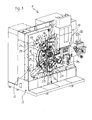
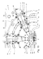
- Forming machine shown is a stamping and bending machine 1, which has a machine frame 3 with a mounting frame 5 and mounted on the mounting frame 5 Umformaggregate 7a - 7e, which are mounted on the mounting frame 5 in an array on a circle.
- the forming units 7a-7e are bending units, each of which has its own numerically controlled electric motor (NC electric motor) with a spindle drive or the like, and a tool carriage drivable for forming movements with a tool 9a-9e fastened thereto.
- NC electric motor numerically controlled electric motor
- NC forming units 7a-7e known from the prior art are aligned with their tool slides and the tools 9a-9e fastened thereto to a central forming point 11, at which a so-called center punch is positioned in the form of a bending mandrel or die element, on which the die is to be formed
- Semi-finished by means of the forming units 7a - 7e is brought into the desired shape.
- the semifinished product is first fed as strip material, the z. B. is handled by a coil.
- the forming machine 1 has an NC-controlled material intake 13 for the material supply, which is preceded by a punching and / or cutting press 15 in the material flow direction.
- the press 15 can thus punch holes, recesses and contours in the supplied strip material.
- the thus prepared strip material then passes as a semi-finished product to the deformation point 11, in which it is formed in successive sections, so that workpieces are produced with the desired shape.
- the works in the Fig. 1 and 2 Punching and bending machine 1 shown similar to the known from the prior art BIMERIC system of Otto Bihler Maschinenfabrik GmbH & Co. KG, D-87642 Halblech.
- New peculiarity of the forming machine according to the invention is the possibility of facilitated (part) automatic installation and retrofitting with forming units 7 in order to produce a specific workpiece can. Explanations will follow with reference to the following FIGS. 3 to 12 ,
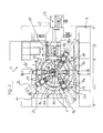
- Fig. 3 shows in isolated view a mounting frame member 17 of the punching and bending machines Fig. 1 and Fig. 2 in perspective view with forming units 7f - 7j provided thereon (it could also be the forming units 7a - 7e from Fig. 1 and Fig. 2 in its arrangement on a circle defined by an annular through hole 19 in the outer wall 21 of the central mounting frame member 17.
- the forming units 7a-7j are fixed to the central mounting frame element 17 by means of holding devices 23, preferably of the same type.
- clamping elements 25 are provided, which engage with sliding blocks 27 in concentric with the annular through hole 19 radially on either side thereof provided in the outer wall 21, undercut Kreisringnuten 29, 31.
- the clamping elements 25 have a helical gear, which allows tightening of the sliding blocks against the undercuts of the receiving them Kreisringnuten 29, 31, so that the relevant support means 23 can be securely fixed to the outer wall 21 of the central mounting frame member 17 by clamping.
- the clamping elements 25 engage with a respective stop step 33 to a complementary flange 35 of the mounting device 23 at the front to the mounting device 23 to be able to fix the outer wall 21 by clamping (see. FIGS. 7, 8, 11 u. 12).
- each support means 23 four clamping elements 25 are assigned, of which two are received in a respective annular groove 29 and 31 with their groove stones.
- the mounting device 23 comprises two basic components, namely a circular base part 37 in the example and a rotary mounting part 39 rotatably mounted thereon, to which the actual forming unit is to be fastened.
- Such a construction of the mounting device 23 enables a precise angular adjustment of the forming unit 7 fixed thereto relative to the deformation point 11 (cf. Fig. 1 u. Fig. 2 ).
- This possibility of adjusting the angle is indicated by the example of the forming units 7c and 7e by a dot-dashed and angularly slightly offset image of the respective forming unit.
- the support means 23 each have on the outer wall 21 of the mounting frame member 17 facing the back of the base member 37 on a circular projection 41 which is interrupted centrally and carries at its outer ends in each case a counter-holding element in the form of a sliding element, wherein the circular arc-shaped projection 41 the Has curvature of the annular through hole 19 and is received therein, so that the sliding elements 43 on the inside 22 of the Outer wall 21 of the mounting frame member 17 are located and the outer wall 21 engage behind the inside 22.
- the longitudinally shaped sliding elements 43 can be rotated to attach the mounting device 23 to the outer wall 21 of the mounting frame member 17 so that they are aligned longitudinally with the circular arc-shaped projection 41 and thus can be performed from the outside through the annular through hole 19. Thereafter, they can be transposed by turning by means of a screwing tool or the like., So that they in the FIGS. 8 and 11 take recognizable position in which they no longer fit through the through hole 19. This is a stable stop position.
- the base part 37 of the mounting device 23 Centered in the area of the interruption of the annular projection 41, the base part 37 of the mounting device 23 has a bore 45 and a coupling mechanism 47 received therein for a positioning device 49 to be described later for positioning forming units 7 in a respective desired working position on the outer wall 21 of the mounting frame element 17 on.
- positioning means 49 comprises a on the inside 22 of the outer wall 21 of the mounting frame member 17 rotatably mounted, central large gear 51 (adjusting), which in Fig. 4 is shown without details of the peripheral teeth.
- the gear 51 is aligned with its axis of rotation coaxially with the circle center axis 53 of the annular through hole 19.
- An NC drive unit 55 is fixed to the inner side 22 of the outer wall 21 so that it can turn the large gear 51 meshing therewith with an associated drive pinion (at 57).
- the coupling unit 59 On the outer wall 21 facing away from the end face of the large gear 51, a coupling unit 59 is mounted, which is carried on rotation of the large gear 51 of this.
- the coupling unit 59 comprises a coupling drive 61 with an NC electric motor 62 and one with its longitudinal axis parallel to the circular center axis 53 and in alignment with the annular through hole 19 oriented, elongated coupling element 63 which passes through a hole at 64 in the large gear 51 and is axially movable by the coupling drive 61 between a passive position and a coupling position.
- the coupling element 63 is an elongated sleeve with an in Fig.
- the coupling drive 61 is part of a combined drive assembly 67, which further comprises a controllable rotary support drive 69 for the rotation support part 39 of the support means 23.
- the rotary support drive 69 can be used to align the feed angle of an aggregate 7 relative to the working direction of a respective tool.
- the rotary support actuator 69 has an NC electric motor 71, which via an angular gear, z. B. bevel gear, a in Fig. 5 discernible hollow shaft 73 for rotation drives, in which a rotary actuating shaft 75 is rotatably received for positive rotation, but axially displaceable.
- This rotary operation shaft 75 is passed through the sleeve-shaped coupling member 63 so that it is also aligned parallel to the circular center axis 53 and in alignment with the annular through hole 19.
- the rotary actuating shaft 75 is coupled for common axial displacement, but it is rotatable relative to the non-rotatable coupling element 63.
- the coupling element 63 is dimensioned so that it can pass through the annular through hole 19 from the inside 22 of the outer wall 21 of the mounting frame member 17, with appropriate positioning relative to a outside of this outer wall 21 arranged mounting means 23 a Umformaggregates 7 with the coupling mechanism 47 of Bracket device 23 coupled engage can, as in the 10 and 11 is indicated.
- the coupling element 63 comes in the interruption of the annular projection 41 and meets a detent element 77 of the coupling mechanism 47 of the support means 23.
- This detent element 77 is first by means of the compression spring 79 in the in Fig. 9 shown biased locking projection position in which it protrudes on the base part 37 of the support means 23 to the outside.
- the coupling element 63 Upon further axial displacement of the sleeve-shaped coupling element 63 in its coupling position, the coupling element 63 displaces the locking element 77 out of the latching projection position inwards into the mounting device, as shown in FIG Fig. 10 is recognizable.
- the coupling unit 59 of the positioning device 49 is coupled to the respective mounting device 23 so that the large gear 51 can take along the coupled mounting device 23 along the annular through hole 19 during its rotation.
- the prerequisite is that previously the clamping elements 25 are released so that the support means 23 is released for such movement.
- the axial pressure exerted by the sleeve-shaped coupling element 63 on the latching element 77 and the spring 79 on the mounting device 23 is absorbed by the sliding elements 43, which are supported on the inside of the outer wall 21, so that the support device 23 during its entrainment along the annular Through hole 19 guided on the outer wall 21 and on the coupling element 63 remains.
- FIGS. 7 and 9 show two guided in arcuate slots 85 fasteners 87 in the form of flange sleeves 87 which are penetrated by screws 89 and are taken out with their widened flange 91 in widened recesses along the slots 85.
- the screws 89 connect, by means of the flange sleeves 87, the rotary support part 39 to the base part 37 of the mounting device 23, so that a rotation of the rotary support part 39 relative to the base part 37 is possible by a rotation angle bounded by the arcuate slots 85.
- the screwing of the parts 37, 39 by means of the screws 89 and the flange sleeves 87 leaves a game between the parts 37, 39 of the support means 23, so that the relative rotation between these two parts 37, 39 without excessive force is possible.
- the support members 37, 39 may be acted upon by exciting means 92, for example.
- the mounting device 23 of this forming unit is first, for example, grown at the lowest point of the annular through hole 19, so that the sliding elements 43 passed through the through hole 19 and then into the in Fig. 8 and Fig. 11 recognizable locking position can be rotated so that they engage behind the outer wall 21 of the mounting frame member 17 inside. Further, the support means is provisionally fixed at least with a clamping element 25 in this lower position on the mounting frame, so that it has with its tapered end 93 upwards. These cultivation steps are carried out by the fitter. Then, a routine of the positioning program of a control unit controlling the NC drive unit 55 of the gear 51 and also the coupling drive 61 and the rotation support drive 69 is started.
- the programmed control device controls now the NC drive unit 55 so that the large gear 51 (actuator) is rotated so far that the coupling unit 59 with its sleeve-shaped coupling member 63 axially in Escape with the bore 45 in the base part 37 of the mounting device 23 comes.
- the coupling drive 61 is activated to axially advance the coupling member 63 from its retracted passive position to the coupling position, penetrating the annular through hole 19 in the outer wall 21 of the mounting frame member 17 and displacing the locking projection 77 into the support means 23 to come into coupling engagement with the base part 37 of the mounting device 23.
- the rotary actuation shaft 75 comes into rotary engagement with the complementary insertion opening 83 of the rotary support part 39 of the mounting device 23.
- the fitter can now release the clamping members 25 to release the automatic positioning support means 23 to its desired set working position.
- the control device controls the NC drive unit 55 again in order to turn the large gear 51 into a position in which the coupled mounting device 23 is set down on the annular through hole 19 and is intended to remain.
- the rotation support drive 69 can be activated to set the rotation support part 39 of the support means in a target angular position relative to the base part 37. Once this has been done, the fitter can now fix the mounting device 23 by means of the clamping elements 25 on the outer wall 21 of the mounting frame element 17.
- the outer wall 21 of the mounting frame member 17 has recesses 93 on its outer side, which are distributed along the annular through hole 19, these locking recesses are complementary to the locking elements 77 of the support means 23, so that a relevant Detent recess 93 can receive a biased in its locking projection position locking element 77.
- defined receiving points for the support means 23 are provided, which facilitates the control operation in coupling the coupling device and the rotary actuating means.
- at least some of the recesses 93 are located at locations along the annular through-hole 19 that correspond to attachment points of any conventional predecessor machines. This facilitates the user to switch from a conventional predecessor machine to the forming machine according to the invention, if he wants to continue the series production of a particular workpiece, which he has already made on the previous machine.
- an opening 94 In the center of the outer wall 21 of the mounting frame member 17 is an opening 94, through which a center punch, so as a bending mandrel, a die or the like. From the inside to the outside of the outer wall 21 is movable to set position at the respective Umformstelle 11 reach.
- This center punch transport is preferably carried out with an NC drive unit under control of the control device.
- the support members 23 provides that the Drehhalterungsteil 39 of the support means 23 has an integrated reduction gear, preferably cycloidal or Gleitkeilgetriebe, which can receive the rotary actuator shaft 75 in its rotational engagement position on the input side for receiving torque.
- a reduction gear allows a particularly finely resolved rotation of the rotary support member 39 and thus an attached forming unit or work unit relative to the base member 37th
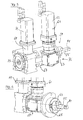
- Fig. 12 is a perspective view of a support means 23 with integrated reduction gear (cyclone gear) and shown with clamping elements 25, namely their outwardly facing mounting side. It carries an adapter plate 95 for attaching a special Umformaggregates or working aggregate, such as a drilling unit, thread cutting unit or the like. This adapter plate 95 is part of the Garrungseinrichung 23 and also serves to center the reduction gear and torque transfer.
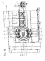
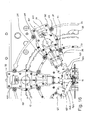
- Fig. 13 shows a perspective view of a forming machine according to the invention. It is the one in the Fig. 1 and 2 shown punching and bending machine 1, compared to that in the Fig. 1 and 2 punching and bending machines shown an additional forming unit 7f and a second punching and / or cutting press 15 has.
- the feed direction which lies in the longitudinal direction of the forming units 7a to 7f, can be aligned in parallel for all the forming units 7a to 7f.
- the feed directions of the forming units 7a to 7f are aligned vertically.
- the forming units 7a to 7f can also face each other at arbitrary other angles to the force of gravity.
- the forming units for processing advanced tool carrier for example, for a mutual tool engagement aligned with each other, such as in the forming units 7a and 7f, 7b and 7e and 7c and 7d.
- a pair of forming units may be located outside the center of the annular through-hole 19.
- the Umformstelle 11 is arranged in the middle of the annular through hole 19.
- a receptacle is shown, to which a holding tool for the workpieces to be produced can be connected.
- the holding tool may have guideways in which move tools that are advanceable with a forming unit.
- the forming units are preferably freely accessible from the environment of the machine.
- the deformation point 11 is preferably freely accessible from the environment of the forming machine.
- Fig. 14 schematically shows a mounting device 23 with a base part 37 and a rotary support member 39 in a section through a rotation axis 100 of an adapter plate 109.
- a Gleitkeilgetriebe is integrated.
- the Gleitkeilgetriebe comprises a drive adapter 101 which rotatably in bearings 102 and 103 in the base member 37 about the axis 100 is stored.
- An elliptical disk 104 is fastened, preferably screwed, to the drive adapter 101.
- the elliptical disk 104 may be integral with the drive adapter 101.
- a rolling bearing 105 having an elliptic rolling bearing track is disposed at the elliptical outer periphery of the elliptical disk 104.
- the rolling bearing 105 supports an externally toothed ring portion 106 of a sleeve 108 rotatably relative to the elliptical disk 104.
- the external teeth of the ring portion 106 engages the peripheral portions of the elliptical disk 104 with the largest radius in an internal toothing of a ring gear 107.
- the ring gear 107 is rotationally connected to the base member 37 or alternatively formed integrally therewith.
- the central axis of the ring gear 107 coincides with the axis of rotation 100.
- the toothed ring portion 106 is connected via the sleeve 108 with the turntable 109, which forms the output of the transmission.
- the two meshing engagement points between the externally toothed ring portion 106 and the internally toothed ring gear 107 rotate with the rotation of the drive adapter 101 in the ring gear 107. Since the external toothing of the ring portion 106 is provided with fewer teeth than the ring gear 107, moves through the tooth difference of the externally toothed ring portion relative to the ring gear 107.
- a bore can be provided in the base part 37 and in the rotary support part 39 with which a forming unit 7 placed on the mounting device 23 can be aligned with a center of the machine, if the Bore in the base part and the bore in the Drehhalterungsteil be aligned.
- a pin can be inserted into both holes.
- a bore may also be arranged in the adapter plate 109 instead of in the rotary holder part 39.
- Fig. 14a shows a section of the in Fig. 14 shown cross-section, which also differs in that a coupling element 63 and a rotary actuating shaft 75 with the support means 23 are engaged.
- the rotary operation shaft 75 is inserted inside the drive adapter 101.
- the interior of the drive adapter 101 has a polygonal cross-section which is compatible with a cross-section of the outer circumference of the rotary actuation shaft 75, so that the rotary actuation shaft 75 can be rotationally inserted into the drive adapter 101.
- the outer periphery of the rotary actuating shaft 75 has a square, preferably with chamfered or rounded corners.
- the rotary actuation shaft 75 also passes through the interior of the latching element 77.
- An end face of the coupling element 63 bears against the end face of the latching element 77 facing away from the mounting device 23. If the coupling element 63 is advanced in the direction of the mounting device 23, then the detent element 77 dips into the interior of the mounting device 23. In this case, compression springs 79 are compressed. The compression springs 79 are preferably arranged at least partially in recesses in the latching element 77 and preferably in its axial direction. The latching element 77 can be pushed into the base part 37 far enough so that the outer surface of the base part 37 is at least flush with the end face of the latching element 77 facing away from the mounting device 23, or it dips further into the interior of the base part 37. In this position, the support means 23 can be moved with respect to the mounting frame 5.
- the mounting device 23 has a pretensioning device for the rotary mounting part 39.
- A here designed as a compression spring element spring 92 is supported on the base part 37.
- the compression spring element 92 is arranged in a recess in the base part 37, wherein the recess is closed by a plug, on which the compression spring element 92 is supported.
- the plug may be designed, for example, as a grub screw or pressed-in pin or the like.
- the compression spring member 92 acts on the rotation support member 39 by the compression spring member 92 pushes the rotation support member 39 in the direction of the adapter plate 109 of the base member 37.
- the compression spring element 92 is seated on a contact element 112, which forwards the pressure forces to the rotary support part 39. In this way, the base member 37 and the rotary support member 39 are biased against each other.
- a plurality of compression spring elements 92 are arranged around the axis of rotation 100 with the same radius with respect to the axis of rotation 100.
- the axial mobility between the base member 37 and the rotary support member 39 By the bias of the compression spring member 92, the Drehhalterungsteil 39 is pressed against the flange sleeves 87, unless the Drehhalterungsteil 39 with the groove stones 27 to the Mounting frame 5 is pulled.
- the rotary support member 39 in this case does not contact the outer wall 21 of the mounting frame member 17, but a small distance, for example 0.2 mm, is maintained between the outer wall 21 and the rotary support member 39. In this way, the rotary support member 39 can be rotated regardless of the position of the base member 23.
- At least two sliding blocks 27 are provided on the rotary support part 39, one of which is intended for engagement in the groove 29 or 31 in one embodiment.
- the distance between the sliding blocks 27 is variable from the axis of rotation 100.
- a longitudinal groove or a longitudinal shoulder may be provided, in or on which an attachment of a sliding block 27 is displaceable.
- Fig. 15 shows a section of a view of the forming machine with a plurality of forming units 7, which are mounted on the mounting frame 5.
- Each of the forming units 7 carries a tool 120, with which a workpiece can be processed, which is attached to a central Umformstelle 11.
- a workpiece holder 122 is arranged.
- Each of the forming units 7 has a feed direction 121, in which the tools 120 can be advanced and withdrawn.
- the workpiece holder 122 has guides 123 in which tools 120 are movable.
- the leadership of in FIG. 15 shown tool 120 is hidden by this.
- Fig. 3 shows how the inclination sensors 124 can be applied to a guide 123 to determine their angular orientation.
- the sensors are capacitive tilt sensors that can measure the angle of the guideway with respect to gravity. This serves to provide an angle specification for the alignment of the forming units 7, so that their feed direction 121 coincides with the guide direction of the guides 123.
- the tools provided for the guidance in the guides 123 are dismantled.
- the guide angle sensors 124 are reversibly fastened to the guides 123. Alternatively to the embodiment with two guide angle sensors 124 in the FIG. 15 If only a single guide angle sensor 124 can be provided.
- a guide angle sensor 124 is preferably applied to a guide surface of a guide 123 which extends at least approximately radially to the center axis 53.
- FIG. 16 shows the view FIG. 15 with the difference that the forming units 7 are not shown.
- the viewer's gaze therefore falls on the rotary support parts 39 provided for the forming units 7.
- An aggregate angle sensor 125 is in each case rotationally fixed to the rotary support parts 39 attached. With an aggregate angle sensor 125, a feed direction 121 of a forming unit 7 can thus be determined.
- the signal measured by the aggregate angle sensor 125 is related to the feed direction 121, wherein an offset may be to be added or subtracted. The offset may result from angular deviations to a zero position of an Aggegatwinkeisensors 125.
- the angular position of the feed direction 121 can be adjusted so that it coincides with the guide direction of a guide 123.
- the signal of an aggregate angle sensor 125 can be compared with a signal of a guide angle sensor 124, and the changing of the angular position of the unit 7 can be continued until the angular position of the feed device 121 coincides with the guide direction of a guide 123.
- an offset between the measured value of a guide angle sensor 124 and the actual position of a guide direction of a guide 123 must be taken into account.
- the adjusting element 51 can be adjusted, whereby the angular position of a forming unit 7 changes.
- the angular position can be effected by turning the Drehhalterungsteils 39.
- the measured signal of an aggregate angle sensor 125 results from two adjustment options, it is preferable to additionally detect at least one of the setting angles of the adjusting element 51 or of the rotation angle of the rotary holding part 39 separately, in order to obtain a distance of the in FIG. 15 can be determined from the center axis 53 coincide with the feed direction 121 longitudinal central axis of a forming unit 7.
- a displaceability of the clamping elements 25 may be realized by means of a projection 35 on a Drehhalterungsteil 39, wherein a clamping element 25 is supported on the projection 35 to pull down the projection 35 and thus tighten the Drehhalterungsteil 39 and at the same time the base part.
- the clamping elements 25 are not connected to the rotary support part 39, but to the base part 37. Since the base part 37 does not rotate with respect to the annular grooves 29 and 31, an alignment for all rotational angles of the rotary holding part 39 thus remains ensured.
- the rotary support member 39 may be fixed to the base member 37 with an additional fixing mechanism. The latter embodiments can be applied to all embodiments of the forming machine.
- the rotation of the angular position of the unit 7 on a mounting device 23 can also take place when the mounting device 23 does not include an integrated reduction gear.
Landscapes
- Engineering & Computer Science (AREA)
- Mechanical Engineering (AREA)
- Bending Of Plates, Rods, And Pipes (AREA)
- Machine Tool Units (AREA)
- Press Drives And Press Lines (AREA)
Abstract
Description
Die vorliegende Erfindung betrifft eine Umformmaschine, insbesondere Biegemaschine, mit wenigstens einem Umformaggregat, vorzugsweise jedoch mit mehreren Umformaggregaten, die mittels Halterungseinrichtungen außen an einer Außenwand eines Montagerahmens in ihrer jeweiligen Soll-Arbeitsposition montiert sind und die zur Ausführung von Umformbewegungen antreibbare Umformwerkzeuge aufweisen, welche auf ein üblicherweise blechförmiges oder drahtförmiges und an einem Dorn, Gesenk oder dgl. abgestütztes Halbzeug umformend einwirken, um ein Werkstück der jeweils gewünschten Form herzustellen. Der Begriff Umformwerkzeug kann im Rahmen der vorliegenden Erfindung auch Bearbeitungswerkzeuge wie z. B. Bohraggregate, Gewindeschneidaggregate, Materialauftragsaggregate u. dgl. umfassen.The present invention relates to a forming machine, in particular bending machine, with at least one forming unit, but preferably with a plurality of Umformaggregaten which are mounted by means of support means on the outside of an outer wall of a mounting frame in their respective desired working position and which have drivable for performing forming movements forming tools, which a usually sheet-shaped or wire-shaped and supported on a mandrel, die or the like. Semifinished deforming act to produce a workpiece of the desired shape. The term forming tool can in the context of the present invention, machining tools such. B. drilling units, thread cutting units, material application units u. Like. Include.
Aus dem Stand der Technik sind solche Umformmaschinen, z. B. als Biegeautomaten für die Serienfertigung von Biegeteilen, in diversen Ausgestaltungen bekannt.From the prior art are such forming machines, z. B. as bending machines for the mass production of bent parts, known in various embodiments.
So sind z. B. konventionelle Biegeautomaten in der
Es sind auch bereits Biegeautomaten bekannt geworden, bei denen das Antriebskonzept des Drehmomentabgriffs von einem zentralen Großzahnrad für die Biegaggregate aufgegeben wurde zugunsten von Biegeaggregaten, die eigene nummerisch gesteuerte Antriebe in Form von Elektromotoren aufweisen. Die Bewegungsabläufe bei den Umformbewegungen solcher Biegeaggregate laufen dabei programmgesteuert ab. Auf die herkömmlichen Kurvenscheiben kann dabei verzichtet werden, so dass das Einrüsten und Umrüsten des Biegeautomaten nicht mehr die Bereitstellung und Montage von Kurvenscheiben beinhaltet, sondern eine entsprechende Änderung des Steuerprogramms für das jeweilige NC-Antriebsaggregat erfordert. NC-Biegeaggregate können überdies in vielfältigeren Soll-Arbeitspositionen an der Außenwand des Montagerahmens positioniert werden, da die Anbindung an ein zentrales Großzahnrad nicht mehr erforderlich ist. Ein Beispiel für einen solchen Biegeautomaten mit nummerisch gesteuerten NC-Biegeaggregaten wird von der Otto Bihler Maschinenfabrik GmbH & Co. KG, D-87642 Halblech, unter der Produktbezeichnung BIMERIC BM 306 vertrieben.There are already known bending machines in which the drive concept of Drehmomentabgriffs was abandoned by a central large gear for the bending units in favor of Biegeaggregaten having their own numerically controlled drives in the form of electric motors. The movements during the forming movements of such bending units run programmatically. On the conventional cams can be dispensed with, so that the installation and retrofitting of the bending machine no longer includes the provision and installation of cams, but requires a corresponding change in the control program for each NC drive unit. NC bending units can also be positioned in a variety of desired working positions on the outer wall of the mounting frame, as the connection to a central large gear is no longer required. An example of such a bending machine with numerically controlled NC bending units is sold by Otto Bihler Maschinenfabrik GmbH & Co. KG, D-87642 Halblech, under the product name BIMERIC BM 306.
Aufgabe der vorliegenden Erfindung ist es, eine Umformmaschine, insbesondere einen Biegeautomaten, bereitzustellen, die eine weitgehende Vereinfachung der Einrüstung bzw. Umrüstung der Maschine, d.h. der Positionierung der Umformaggregate in ihren Soll-Arbeitspositionen im Hinblick auf eine bestimmte Umformaufgabe erlaubt.The object of the present invention is to provide a forming machine, in particular a bending machine, which substantially simplifies the retrofitting of the machine, i. the positioning of the forming units in their desired working positions with respect to a certain forming task allowed.
Zur Lösung dieser Aufgabe wird eine Umformmaschine, insbesondere Biegeautomat gemäß Anspruch 1 vorgeschlagen. Die erfindungsgemäße Umformmaschine umfasst wenigstens ein Umformaggregat mit einer Halterungseinrichtung und mit einem zur Ausführung von Umformbewegungen gesteuert antreibbaren Umformwerkzeug, ein Maschinengestell mit einem eine Außenwand aufweisenden Montagerahmen zur Aufnahme des wenigstens einen Umformaggregates in einer jeweiligen Soll-Arbeitsposition außenseitig an der Außenwand des Montagerahmens, eine Steuereinrichtung und eine Positionierungseinrichtung zur Positionierung des wenigstens einen Umformaggregates in einer betreffenden Soll-Arbeitsposition an der Außenwand des Montagerahmens, wobei die Positionierungseinrichtung folgende Merkmale aufweist:
- ein kreisringförmiges Durchgangsloch in der Außenwand des Montagerahmens mit einer zur Kreisringebene des Durchgangsloches orthogonalen Kreiszentrumsachse, wobei das wenigstens eine Umformaggregat mit seiner Halterungseinrichtung entlang dem kreisringförmigen Durchgangsloch verschiebbar an dem Montagerahmen geführt ist, um es in eine jeweiliges Soll-Arbeitsposition zu bewegen,
- ein um die Kreiszentrumsachse drehbar gelagertes Verstellelement innenseitig der Außenwand des Montagerahmens, wobei das Verstellelement eine mittels der Steuereinrichtung steuerbare Drehantriebseinrichtung aufweist, mittels welcher das Verstellelement relativ zu dem kreisringförmigen Durchgangsloch in eine jeweils gewünschte Position verdreht werden kann,
- eine an dem Verstellelement angeordnete und von diesem mitgeführte Kopplungseinheit, die mittels der Steuereinrichtung steuerbar ist zur wahlweisen Kopplung des Verstellelementes mit der Halterungseinrichtung des wenigstens einen Umformaggregates durch das kreisringförmige Durchgangsloch hindurch, so dass das Verstellelement bei seiner Drehbewegung die Halterungseinrichtung und damit das Umformaggregat entlang dem kreisringförmigen Durchgangsloch mitbewegen kann, um das Umformaggregat zu einer gewünschten Soll-Arbeitsposition zu verlagern, wobei die Halterungseinrichtung zur Festlegung der Soll-Arbeitsposition an dem Montagerahmen fixierbar ist.
- an annular through hole in the outer wall of the mounting frame having a circular center axis orthogonal to the annular plane of the through hole, the at least one forming unit being slidably guided with its support means along the annular through hole to the mounting frame to move it to a respective desired working position;
- a rotatably mounted about the circular center axis adjusting element inside the outer wall of the mounting frame, wherein the adjusting element a controllable by the control means rotary drive means, by means of which the adjusting element can be rotated relative to the annular through hole in a respective desired position,
- a arranged on the adjusting and entrained by this coupling unit, which is controllable by means of the control device for selectively coupling the adjusting element with the support means of the at least one forming unit through the annular through hole, so that the adjusting element during its rotational movement, the support means and thus the forming unit along the can move with annular through hole to move the forming unit to a desired desired working position, wherein the support means for fixing the target working position on the mounting frame is fixable.
Die so ausgestaltete Umformmaschine nach der Erfindung erlaubt eine rechnergesteuerte und somit automatische Positionierung der für den jeweiligen Umformprozess erforderlichen Umformwerkzeuge in deren Soll-Arbeitspositionen außenseitig an der Außenwand des Montagerahmens. Es können dabei mehrere Umformaggregate entlang dem kreisringförmigen Durchgangsloch in der Außenwand des Montagerahmens verteilt angeordnet und in ihrer Soll-Arbeitsposition justiert und fixiert werden. Die Umformaggregate sind individuell steuerbar, so dass ihre Umformwerkzeuge die gewünschten vorgegebenen Umformbewegungsabläufe durchführen. Vorzugsweise handelt es sich bei den Umformaggregaten um NC-Aggregate mit elektromotorischem Antrieb der Umformwerkzeuge. Die Kreisringebene des Durchgangsloches entspricht normalerweise der Anbaufläche (Außenfläche) der Außenwand des Montagerahmens. Vorzugsweise erstreckt sie sich vertikal.The thus configured forming machine according to the invention allows a computer-controlled and thus automatic positioning of the forming tools required for the respective forming process in their desired working positions on the outside of the outer wall of the mounting frame. It can be distributed distributed along the annular through hole in the outer wall of the mounting frame and adjusted in their desired working position and fixed several Umformaggregate. The forming units are individually controllable, so that their forming tools perform the desired predetermined Umformbewegungsabläufe. Preferably, the forming units are NC units with electromotive drive of the forming tools. The circular ring plane of the through hole normally corresponds to the mounting surface (outer surface) of the outer wall of the mounting frame. Preferably, it extends vertically.
Die Vorgabe der Anordnung der Umformaggregate auf einem Kreisring ist aus zweierlei Gründen vorteilhaft. Der erste Grund ist die Möglichkeit, das Verstellelement relativ einfach zu gestalten und auf einfache Weise zu einer Drehbewegung (Winkeländerungsbewegung) anzutreiben. Der zweite Grund besteht in der geometrischen Ähnlichkeit dieser Anordnung zu der Kreisanordnung von Umformaggregaten bei konventionellen Biegeautomaten gemäß der oben erwähnten
Die Übernahme der Anordnungsgeometrie der Umformaggregate von konventionellen Umformmaschinen auf eine Umformmaschine bietet ferner den Vorteil, dass als drehbares Verstellelement der Positionierungseinrichtung ein dem zentralen Großzahnrad in Form und Lagerung am Montagerahmen entsprechendes Zahnrad verwendet werden kann, um damit die Kopplungseinheit innenseitig der Außenwand des Montagerahmens längs dem kreisringförmigen Durchgangsloch zu bewegen, um ein jeweiliges Umformaggregat anzukoppeln und ggf. an eine neue Position auf dem kreisringförmigen Durchgangsloch zu versetzen.The assumption of the geometry of the Umformaggregate of conventional forming machines on a forming machine also has the advantage that as a rotatable adjusting the positioning means a central gear in the form and storage on the mounting frame corresponding gear can be used to order the coupling unit inside the outer wall of the mounting frame along the to move annular through hole to couple a respective forming unit and possibly to move to a new position on the annular through hole.
Es können somit Konstruktionsmerkmale konventioneller Umformmaschinen vorteilhaft übernommen werden.It can thus be taken over advantageous design features of conventional forming machines.
Die Steuerung der Positionierungseinrichtung erfolgt mittels einer Steuereinrichtung nach entsprechenden Programmen, wobei bei der Programmerstellung Optimierungsstrategien zur Positionierung der betreffenden Umformaggregate in Soll-Arbeitspositionen unter Berücksichtigung der Geometrie des herzustellenden Werkstückes verfolgt werden können.The control of the positioning device by means of a control device according to programs, which can be followed in the program creation optimization strategies for positioning the respective Umformaggregate in desired working positions, taking into account the geometry of the workpiece to be produced.
Die Positionierungseinrichtung kann bei der Ersteinrüstung der Umformmaschine mit Umformaggregaten und auch bei weiteren Umrüstungen der Umformmaschine genutzt werden, um den jeweiligen Rüstvorgang auf vergleichsweise einfache und insbesondere schnelle Weise durchzuführen. Der typische Ablauf bei der Verlagerung eines Umformaggregates an der Außenwand des Montagerahmens beginnt mit der Drehbewegung des Verstellelementes um die Kreiszentrumsachse des kreisringförmigen Durchgangsloches, bis die von dem Verstellelement mitgeführte Kopplungseinheit in axiale Ausrichtung zu dem auf der anderen Seite der Außenwand des Montagerahmens angeordneten Umformaggregat kommt. Sodann tritt die Kopplungseinheit mit der Halterungseinrichtung des Umformaggregates durch das kreisringförmige Durchgangsloch hindurch in Kopplungseingriff, um das Umformaggregat für die folgende Umsetzbewegung anzukoppeln. Gegebenenfalls sind nun noch Fixierelemente, die das Umformaggregat in der bisherigen Position an der Außenwand des Montagerahmens fixiert haben, zu lösen, so dass das Umformaggregat nebst Halterungseinrichtung zur Bewegung mit der Kopplungseinheit längs dem kreisringförmigen Durchgangsloch freigegeben ist. Sodann erfolgt eine weitere Drehbewegung des Verstellelementes, bis das Umformaggregat seine neue Winkelposition auf dem kreisringförmigen Durchgangsloch erreicht hat. Nach Justierung und Fixierung des Umformaggregats in der gewünschten neuen Soll-Arbeitsposition erfolgt dann die Abkopplung der Kopplungseinheit von der Halterungseinrichtung des Umformaggregates, so dass die Positionierungseinrichtung nun zur Aufnahme eines nächsten Umformaggregates bereitsteht.The positioning device can be used in the initial equipment of the forming machine with Umformaggregaten and also in other conversions of the forming machine to the respective setup process to comparatively simple and in particular fast way to perform. The typical sequence in the displacement of a Umformaggregates on the outer wall of the mounting frame begins with the rotational movement of the adjusting element about the circular center axis of the annular through hole until the entrained by the adjusting coupling unit comes in axial alignment with the arranged on the other side of the outer wall of the mounting frame forming unit. Then, the coupling unit with the holding device of the forming unit passes through the annular through hole in coupling engagement to couple the forming unit for the following transfer movement. If necessary, fixing elements which have fixed the shaping unit in the previous position on the outer wall of the mounting frame are now also to be loosened, so that the forming unit together with the mounting device is released along with the annular through-hole for movement with the coupling unit. Then there is a further rotational movement of the adjusting element until the forming unit has reached its new angular position on the annular through hole. After adjustment and fixation of the forming unit in the desired new desired working position, the decoupling of the coupling unit then takes place from the mounting device of the forming unit, so that the positioning device is now ready to receive a next forming unit.
Das kreisringförmige Durchgangsloch kann einen insgesamt geschlossenen Kreisring beschreiben. Unter dem Begriff "kreisringförmiges Durchgangsloch" soll im Rahmen der vorliegenden Erfindung jedoch ggf. auch ein kreisringförmiges Durchgangsloch fallen, welches keinen vollständig geschlossenen Kreisring sondern einen Kreisbogen beschreibt. Außerdem kann unter den Begriff auch ein kreisförmiges Loch fallen, wobei ein Teil des Inneren des Lochs durch ein Element der Umformmaschine verschlossen ist, sodass sich ein kreisförmiges Loch oder eine kreisförmige Nut ergibt. Dieses Element der Umformmaschine kann an dem Verstellelement befestigt sein und dreht sich dann mit dem Verstellelement. Alternativ kann das Element der Umformmaschine mit dem Montagerahmen verbunden sein, wobei die Verbindung durch ein Loch in dem Verstellelement verläuft.The annular through hole may describe an overall closed circular ring. In the context of the present invention, however, the term "circular through-hole" is also intended to include an annular through-hole which does not describe a completely closed circular ring but rather a circular arc. In addition, the term may also include a circular hole wherein a part of the interior of the hole is closed by an element of the forming machine to give a circular hole or a circular groove. This element of the forming machine can be attached to the adjustment and then rotates with the adjustment. Alternatively, the element of the forming machine can be connected to the mounting frame, wherein the connection passes through a hole in the adjustment.
Wie schon erwähnt, kommt als Verstellelement gemäß einer bevorzugten Ausführungsform der Erfindung ein Zahnrad in Frage, wobei der Verstellantrieb ein mit dem Zahnrad kämmendes Antriebsritzel aufweist. Das Antriebsritzel wird von einem steuerbaren Elektromotor, also vorzugsweise NC-Antriebsaggregat nach Maßgabe von Steuerbefehlen der Steuereinrichtung angetrieben.As already mentioned, comes as an adjusting element according to a preferred embodiment of the invention, a gear in question, wherein the adjusting drive has a meshing with the gear drive pinion. The drive pinion is driven by a controllable electric motor, so preferably NC drive unit in accordance with control commands of the control device.
Gemäß einer besonders vorteilhaften Ausführungsform der Erfindung umfasst die Halterungseinrichtung des Umformaggregats ein Basisteil zur Festlegung an der Außenwand des Montagerahmens und ein an dem Basisteil drehbar gelagertes Drehhalterungsteil, an dem das Umformaggregat im Übrigen befestigbar oder befestigt ist, so dass es relativ zum Basisteil in verschiedene Winkelstellungen einstellbar ist, wobei die Positionierungseinrichtung einen mittels der Steuereinrichtung steuerbaren Drehhalterungsantrieb für das Drehhalterungsteil aufweist. Die so gestaltete Halterungseinrichtung erlaubt somit einen weiteren Positionierungsfreiheitsgrad des Umformaggregates, welches somit zunächst mittels der Kopplungseinheit des Verstellelementes an eine bestimmte Positionierungsstelle auf dem kreisringförmigen Durchgangsloch platziert und dann unter Verbleib an dieser Stelle verdreht werden kann, um das Umformwerkzeug in der gewünschten Weise auszurichten, so dass es die gewünschte Umformoperation an dem im Umformbereich nahe der Zentralachse des kreisringförmigen Durchgangslochs präparierten Umformstelle durchführen kann. Nach der so erfolgten Positionierung des Umformaggregates in seiner neuen Soll-Arbeitsposition sind ggf. Fixiermittel zur Fixierung des Umformaggregates zu betätigen, solange letzteres noch von der Positionierungseinrichtung in Position gehalten wird. Nach der Fixierung kann dann die Abkopplung der Kopplungseinheit und des Drehhalterungsantriebs von dem Umformaggregat bzw. dessen Halterungseinrichtung erfolgen. Es kann im Rahmen der vorliegenden Erfindung auch vorgesehen sein, dass automatische Fixiermittel greifen, um das Umformaggregat mit seiner Halterungseinrichtung in einer neu besetzten Soll-Arbeitsposition zu fixieren.According to a particularly advantageous embodiment of the invention, the support means of Umformaggregats comprises a base part for fixing to the outer wall of the mounting frame and rotatably mounted on the base part Drehhalterungsteil on which the Umformaggregat is otherwise fastened or secured so that it relative to the base part in different angular positions is adjustable, wherein the positioning means comprises a controllable by means of the control device Drehhalterungsantrieb for the Drehhalterungsteil. The support device designed in this way thus permits a further degree of freedom of positioning of the forming unit, which thus can first be placed on the annular through hole by means of the coupling unit of the adjusting element and then rotated while remaining at this point in order to align the forming tool in the desired manner that it can perform the desired forming operation on the forming station prepared in the forming area near the central axis of the annular through-hole. After the successful positioning of the forming unit in its new desired working position, if necessary fixing means for fixing the forming unit are to be actuated, as long as the latter is still held in position by the positioning device. After fixing, the decoupling of the coupling unit and the rotary support drive from the forming unit or its mounting device can then take place. It can also be provided within the scope of the present invention that automatic fixing means engage the forming unit with its holding device in a newly occupied desired working position to fix.
Gemäß einer Weiterbildung der Erfindung hat der Drehhalterungsantrieb eine mit ihrer Längsachse parallel zur Kreiszentrumsachse und in Flucht mit dem kreisringförmigen Durchgangsloch orientierte, zur Drehung um ihre Längsachse antreibbare Drehbetätigungswelle, die zwischen einer Passivstellung und einer Dreheingriffsstellung zur Herstellung eines Dreheingriffs mit dem Drehhalterungsteil der Halterungseinrichtung eines betreffendes Umformaggregates axial bewegbar ist, wobei sie in der Passivstellung zurückgezogen positioniert ist und wobei sie aus dieser Passivstellung heraus das kreisringförmige Durchgangsloch durchsetzend in die Dreheingriffsstellung vorschiebbar ist, um das Drehhalterungsteil der Halterungseinrichtung eines betreffenden Umformaggregates in Dreheingriff zu nehmen. Hierzu kann es gemäß einer Ausführungsform der Erfindung vorgesehen sein, dass die Drehbetätigungswelle einen axial vorderen Einsteckabschnitt mit einem Polygonquerschnitt aufweist, der in eine komplementär geformte Einstecköffnung des Drehhalterungsteils der Halterungseinrichtung eines betreffenden Umformaggregates einführbar ist, um in Dreheingriff mit dem Drehhalterungsteil zu gelangen. Mit einer Umformmaschine gemäß dieser Ausführungsform ist es u. a. möglich, die Umformaggregate an verschiedenen Positionen anzuordnen und zugleich zu bewirken, dass ein paralleler Vorschub von Werkzeugen stattfinden kann.According to one embodiment of the invention, the rotary support drive has a with its longitudinal axis parallel to the circular center axis and in alignment with the annular through hole drivable to rotate about its longitudinal axis rotary actuation shaft between a passive position and a Dreeringriffsstellung for producing a rotational engagement with the Drehhalterungsteil the support means of a respective Umformaggregates is axially movable, wherein it is positioned retracted in the passive position and wherein it is pushed forward from this passive position, the annular through hole in the rotational engagement position to take the Drehhalterungsteil the support means of a respective Umformaggregates in rotational engagement. For this purpose, it may be provided according to an embodiment of the invention that the rotary actuation shaft has an axially front male portion with a polygonal cross-section which is insertable into a complementary shaped insertion of the rotary support member of the support means of a respective Umformaggregates to come into rotary engagement with the Drehhalterungsteil. With a forming machine according to this embodiment, it is u. a. possible to arrange the forming units at different positions and at the same time to cause a parallel feed of tools can take place.
Als Drehhalterungsantrieb kommt vorzugsweise ein an dem Verstellelement angeordneter NC-Elektromotor zum Drehen der Drehbetätigungswelle in Frage, wobei die Drehbetätigungswelle axial verschiebbar relativ zu dem NC-Elektromotor gelagert ist.As a rotary support drive is preferably arranged on the adjusting NC electric motor for rotating the rotary actuating shaft in question, wherein the rotary actuating shaft is mounted axially displaceable relative to the NC electric motor.
Es hat sich als eine besonders vorteilhafte Variante herausgestellt, wenn das Drehhalterungsteil der Halterungseinrichtung ein vorgeschaltetes Untersetzungsgetriebe, insbesondere Zykloidgetriebe oder Gleitkeilgetriebe, z. B. ein Harmonic-Drive-Getriebe, aufweist, welches zur Drehmomentaufnahme eingangsseitig die Drehbetätigungswelle in ihrer Dreheingriffsstellung aufnehmen kann. Das Untersetzungsgetriebe untersetzt den Drehwinkel der Drehbetätigungswelle, z. B. mit einer Übersetzung in der Größenordnung 1 : 100, vorzugsweise über 1 : 100, besonders bevorzugt 1 : 160, so dass auf diese Weise eine sehr große Winkelauflösung bei der Winkelpositionierung des Drehhalterungsteils und des damit verbundenen Umformaggregates möglich ist. Die Winkelpositionierung der Umformaggregate und deren Umformwerkzeug kann auf diese Weise automatisiert mit einer Genauigkeit von wenigen Bogenminuten vorgenommen werden.It has proven to be a particularly advantageous variant, when the Drehhalterungsteil the support means an upstream reduction gear, in particular cycloidal or Gleitkeilgetriebe, z. As a harmonic drive gearbox, which receive the torque input on the input side, the rotary actuation shaft in its rotational engagement position can. The reduction gear reduces the angle of rotation of the rotary actuating shaft, z. Example, with a translation in the order of 1: 100, preferably about 1: 100, more preferably 1: 160, so that in this way a very large angular resolution in the angular positioning of the rotary support member and the associated Umformaggregates is possible. The angular positioning of the forming units and their forming tool can be made in this way automatically with an accuracy of a few minutes of arc.
Die Kopplungseinheit weist vorzugsweise einen mittels der Steuereinrichtung steuerbaren Kopplungsantrieb und ein mit seiner Längsachse parallel zur Kreiszentrumsachse und in Flucht mit dem kreisringförmigen Durchgangsloch orientiertes, längliches Kopplungselement auf, das von dem Kopplungsantrieb zwischen einer Passivstellung und einer Kopplungsstellung axial bewegbar ist, wobei es in der Passivstellung innenseitig der Außenwand des Montagerahmens zurückgezogen positioniert ist und wobei es aus dieser Passivstellung heraus das kreisringförmige Durchgangsloch durchsetzend in die Kopplungsstellung vorschiebbar ist, um die Halterungseinrichtung des betreffenden Umformaggregates koppelnd in Eingriff zu nehmen. Als Kopplungsantrieb kommt ebenfalls ein mittels der Steuereinrichtung steuerbarer NC-Elektromotor in Frage, welcher über ein Planetengetriebe oder ein entsprechendes Umlenkgetriebe das Kopplungselement in die Kopplungsstellung vorschiebt bzw. in die Passivstellung zurückzieht.The coupling unit preferably has a controllable by the control device coupling drive and with its longitudinal axis parallel to the circular center axis and aligned with the annular through hole oriented, elongated coupling element which is axially movable by the coupling drive between a passive position and a coupling position, wherein it in the passive position inside of the outer wall of the mounting frame is positioned retracted and wherein it is advanceable from this passive position out the annular through hole in the coupling position to take the mounting device of the respective Umformaggregates coupling engaged. Another suitable coupling drive is an NC electric motor controllable by means of the control device, which feeds the coupling element into the coupling position or retracts into the passive position via a planetary gear or a corresponding deflection gear.
Insbesondere zur Bauraumminimierung kann es gemäß einer Weiterbildung der Erfindung vorgesehen sein, dass das Kopplungselement eine Hülse ist, in der die Drehbetätigungswelle drehbar aufgenommen ist und die zusammen mit der Drehbetätigungswelle von dem Kopplungsantrieb zwischen der Passivstellung und der Kopplungsstellung axial bewegbar ist. Dieses hülsenförmige Kopplungselement kann somit ein Drehlager für die Drehbetätigungswelle sein, wobei die Drehbetätigungswelle jedoch in Bezug auf axiale Bewegungen mit dem Kopplungselement gekoppelt ist. Auf diese Weise kann der Kopplungsantrieb sowohl für die Axialverschiebung des Kopplungselementes als auch für die Axialverschiebung der Drehbetätigungswelle simultan genutzt werden, was ebenfalls einen erheblichen Vorteil bedeutet.In particular for space minimization, it may be provided according to a development of the invention that the coupling element is a sleeve in which the rotary actuating shaft is rotatably received and which is axially movable together with the rotary actuating shaft of the coupling drive between the passive position and the coupling position. This sleeve-shaped coupling element may thus be a pivot bearing for the rotary actuating shaft, wherein the rotary actuating shaft is coupled with respect to the axial movement with the coupling element. In this way, the coupling drive for both the axial displacement of the coupling element as well as for the axial displacement of the rotary actuation shaft are used simultaneously, which also means a significant advantage.
Die Außenwand des Montagerahmens kann an ihrer Außenseite Rastausnehmungen aufweisen, die entlang der kreisringförmigen Durchgangsöffnung verteilt sind, wobei die Halterungseinrichtung ein axial bewegbar geführtes und mittels Federkraft zu einer Rastvorsprungsstellung vorgespanntes Rastelement an ihrer der Außenwand des Montagerahmens zugewandt gegenüberliegenden Seite aufweist, welches zu den Rastausnehmungen komplementär geformt und in einer der Rastausnehmungen aufgenommen ist, wenn das Umformaggregat in einer betreffenden Soll-Arbeitsposition an dem Montagerahmen positioniert ist. Diese Maßnahmen dienen dazu, ein definiertes Anordnungsraster für die Umformaggregate entlang dem kreisringförmigen Durchgangsloch bereitzustellen und ggf. eine Sicherung eines betreffenden Umformaggregates an der Außenwand des Montagerahmens zu ermöglichen. Das Basisteil der Halterungseinrichtung kann zu diesem Zweck auch Gegenhalteelemente z.B. in Form von Gleitelementen aufweisen, die an einem die kreisringförmige Durchgangsöffnung durchsetzenden Träger angeordnet sind und die Außenwand des Montagerahmens an deren Innenseite hintergreifen, so dass sie der mit ihrem Rastelement in einer Rastausnehmung aufgenommenen Halterungseinrichtung des Umformaggregates definierten Halt an der Außenwand des Montagerahmens geben können, bis eine stabile Fixierung der Halterungseinrichtung an der Außenwand des Montagerahmens mittels entsprechender Fixiermittel erfolgt ist.The outer wall of the mounting frame may have on its outer side recesses which are distributed along the annular passage opening, wherein the support means has an axially movable guided and biased by spring force to a latching protrusion locking element on its outer wall of the mounting frame facing opposite side, which is complementary to the recesses is formed and accommodated in one of the recesses, when the forming unit is positioned in a respective desired working position on the mounting frame. These measures serve to provide a defined arrangement grid for the forming units along the annular through hole and possibly to enable a backup of a respective forming unit on the outer wall of the mounting frame. The base part of the mounting device can also be provided with counter-holding elements, e.g. in the form of sliding elements, which are arranged on a carrier passing through the annular passage opening and engage behind the outer wall of the mounting frame on the inside, so that they can define the recorded with its locking element in a recess recess mounting means of Umformaggregates defined on the outer wall of the mounting frame until a stable fixation of the mounting device is made on the outer wall of the mounting frame by means of appropriate fixing.
Gemäß einer besonders bevorzugten Variante der Erfindung ist das Rastelement von dem Kopplungselement gegen die Federvorspannung aus der Rastvorsprungsstellung und somit aus der jeweiligen Rastausnehmung der Außenwand des Montagerahmens verdrängbar, wenn das Kopplungselement in Ausrichtung zu dem Rastelement in die Kopplungsstellung bewegt wird. Der Rastvorsprung und die Rastausnehmungen können dann keine gegenseitigen Störkonturen mehr in Bezug auf die Verlagerung des betreffenden Umformaggregates längs dem kreisringförmigen Durchgangsloch bilden.According to a particularly preferred variant of the invention, the latching element is displaceable by the coupling element against the spring bias from the latching projection position and thus from the respective latching recess of the outer wall of the mounting frame, when the coupling element is moved in alignment with the latching element in the coupling position. The latching projection and the recesses can then form no mutual interference contours more in relation to the displacement of the respective forming unit along the annular through hole.
Das Kopplungselement greift dabei so weit in die Halterungseinrichtung, insbesondere in deren Basisteil ein, dass es letzteres zur Bewegung entlang dem kreisringförmigen Durchgangsloch in der Außenwand des Montagerahmens mitnehmen kann. Dabei stützt sich die Halterungseinrichtung mit Gegenhalteelementen, z. B. in Form der vorstehend genannten Gleitelemente, innenseitig der Außenwand ab, so dass die Halterungseinrichtung auch dann an der Außenwand verbleibt, wenn die Verrastung zwischen dem oben erläuterten Rastvorsprung und einer betreffenden Rastausnehmung durch das Kopplungselement aufgehoben worden ist.The coupling element engages so far in the support means, in particular in the base part, that it can take the latter for movement along the annular through hole in the outer wall of the mounting frame. In this case, the support device is supported with counter holding elements, for. Example, in the form of the above-mentioned sliding elements, inside of the outer wall, so that the support means also remains on the outer wall when the latching between the above-mentioned locking projection and a respective recess has been canceled by the coupling element.
Es sei an dieser Stelle noch betont, dass die Halterungseinrichtungen der ggf. im Übrigen unterschiedlichen Umformaggregate hinsichtlich der oben beschriebenen Funktionen gleich aufgebaut sind.It should be emphasized at this point that the support means of possibly different otherwise Umformaggregate with respect to the functions described above are the same structure.
Gemäß einer Weiterbildung der Erfindung ist außenseitig an der Außenwand des Montagerahmens radial außerhalb und radial innerhalb des kreisringförmigen Durchgangsloches jeweils eine hinterschnittene Kreisnut vorgesehen, in welcher Nutsteine von Klemmbefestigungselementen zur Fixierung der Halterungseinrichtung aufgenommen sind. Diese Kreisnuten verlaufen konzentrisch zu dem kreisringförmigen Durchgangsloch. Die Klemmbefestigungsteile weisen vorzugsweise Schrauben auf, mittels denen die Nutsteine angezogen werden können, um die Halterungseinrichtung stabil an der Außenwand des Montagerahmens in einer jeweiligen Soll-Arbeitsposition zu fixieren.According to one embodiment of the invention, an undercut circular groove is provided on the outside of the outer wall of the mounting frame radially outside and radially inside the annular through-hole, in which sliding blocks of clamping fastening elements are accommodated for fixing the mounting device. These circular grooves are concentric with the annular through hole. The clamping fastening parts preferably have screws by means of which the sliding blocks can be tightened in order to fix the mounting device stably on the outer wall of the mounting frame in a respective desired working position.
Hinzuweisen ist noch darauf, dass das jeweilige Positionieren mittels der Positionierungseinrichtung auch an den Halterungseinrichtungen vorgenommen werden kann, bevor die Umformaggregate im Übrigen daran angebracht werden. Andererseits kann die Positionierung jedoch auch an den mit Umformaggregaten bereits bestückten Halterungseinrichtungen erfolgen. Mit der bekannten Winkelstellung des Umformaggregats kann dessen Positionierung vereinfacht oder vollständig automatisiert werden.It should also be pointed out that the respective positioning by means of the positioning device can also be made on the holding devices before the forming units are otherwise attached thereto. On the other hand, however, the positioning can also be done on the already equipped with Umformaggregaten mounting means. With the known angular position of the forming unit whose positioning can be simplified or completely automated.
In einer Weiterbildung weist die Umformmaschine einen Aggregatwinkelsensor auf, der mit einem Umformaggregat verdrehfest verbunden oder verbindbar ist, so dass der Aggregatwinkelsensor eine Winkelstellung des Umformaggregats erfasst. Alternativ oder zusätzlich ist es möglich, die Winkelstellung des Umformaggregats mittels der Winkelstellung des Verstellelements gegenüber dem Montagerahmen zu erfassen. Zusätzlich kann das Umformaggregat jedoch über den Drehantrieb und eine Drehung des Drehhalterungsteils gegenüber dem Verstellelement verdreht sein. Dieser Winkel kann u. U. aus dem Drehantrieb oder dessen Ansteuerung abgegriffen werden, insbesondere wenn es sich dabei um einen Schrittmotor oder Servomotor handelt. Gleiches gilt auch für den Antrieb des Verstellelements. Alternativ oder zusätzlich kann ein Winkelsensor mit dem Verstellelement in Wirkverbindung stehen. Die Winkel von Verstellelement und Drehantrieb können rechnerisch kombiniert werden, um zu der Winkelstellung des Umformaggregats zu kommen. Ein Aggregatwinkelsensor hat demgegenüber jedoch den Vorteil, dass er die Winkelstellung des Umformaggregats unmittelbar erfasst, beispielsweise gegenüber dem Montagerahmen oder der Schwerkraft. Im letztgenannten Fall kann ein Neigungssensor eingesetzt werden, besonders bevorzugt ein kapazitiver Neigungssensor.In one development, the forming machine has an aggregate angle sensor, which is rotationally connected or connectable to a forming unit, so that the unit angle sensor detects an angular position of the forming unit. Alternatively or additionally, it is possible to detect the angular position of the forming unit by means of the angular position of the adjusting element relative to the mounting frame. In addition, however, the forming unit can be rotated via the rotary drive and a rotation of the rotary support member relative to the adjusting element. This angle can u. U. be tapped from the rotary drive or its control, especially if it is a stepper motor or servomotor. The same applies to the drive of the adjustment. Alternatively or additionally, an angle sensor can be in operative connection with the adjusting element. The angle of the adjusting element and the rotary drive can be mathematically combined to come to the angular position of the forming unit. An aggregate angle sensor, however, has the advantage that it detects the angular position of the Umformaggregats directly, for example, with respect to the mounting frame or gravity. In the latter case, an inclination sensor can be used, particularly preferably a capacitive inclination sensor.
In einer Weiterbildung der Umformmaschine mit einer Winkelerfassung für ein Umformaggregat weist die Umformmaschine eine Führung für ein Werkzeug auf, das von einem Umformaggregat antreibbar ist, sowie zusätzlich einen Führungswinkelsensor, der an die Führung angelegt oder anlegbar ist und der eine Winkelstellung der Führung erfasst. Vorzugsweise wird zur Messung gegenüber der Schwerkraft ein Neigungssensor, besonders bevorzugt ein kapazitiver Neigungssensor eingesetzt. Vorzugsweise wird die Winkelstellung gegenüber dem Montagerahmen, besonders bevorzugt gegenüber der Schwerkraft erfasst. Mit Hilfe der Bestimmung der Winkelstellung der Führung kann das Umformaggregat so ausgerichtet werden, dass eine Vorschubrichtung des Umformaggregats mit der Führungsrichtung der Führung übereinstimmt. Dazu kann ein manueller Vergleich zwischen den beiden Winkeln vorgenommen werden, besonders bevorzugt wird jedoch eine Winkelvergleichseinrichtung eingesetzt, die einen Vergleich zwischen der Winkelstellung des Umformaggregats und der Winkelstellung der Führung durchführt. Insbesondere kann die Winkelvergleichseinrichtung eine Differenz zwischen den beiden Winkeln ermitteln und besonders bevorzugt die Winkellage des Umformaggregats automatisiert ändern. Die Ausrichtung des Umformaggregats zu der Führung kann beendet werden, wenn die Differenz der Winkelstellung der Führung und der Winkelstellung des Umformaggregats null ist. Alternativ dazu kann die Ausrichtung beendet werden, wenn eine vorgegebene Winkeldifferenz erreicht ist, die einen Winkel zwischen dem Aggregatwinkelsensor und der Vorschubrichtung des Aggregats und/oder zwischen dem Führungswinkelsensor und der Führungsrichtung darstellt. Um die Ausrichtung zu erreichen, können bekannte Steuer- oder Regelverfahren zum Einsatz kommen. Der Führungswinkelsensor ist vorzugsweise temporär an der Führung befestigbar, beispielsweise durch Anschrauben, Festklemmen, reversibles Ankleben, Magnetkräfte oder dergleichen. Vorzugsweise wird im Falle der Messung gegenüber der Schwerkraft der Führungswinkelsensor dabei an einer Führungsfläche der Führung befestigt.In a further development of the forming machine with an angle detection for a forming unit, the forming machine on a guide for a tool which is driven by a forming unit, and in addition a guide angle sensor which is applied to the guide or can be applied and detects an angular position of the guide. Preferably, an inclination sensor, particularly preferably a capacitive inclination sensor, is used for the measurement with respect to gravity. Preferably, the angular position relative to the mounting frame, particularly preferably detected against gravity. With the help of the determination of the angular position of the guide, the forming unit can be aligned so that a feed direction of the forming unit coincides with the guide direction of the guide. For this purpose, a manual comparison between the two angles can be made, but particularly preferred is a Angle comparison device used, which performs a comparison between the angular position of the Umformaggregats and the angular position of the guide. In particular, the angle comparison device can determine a difference between the two angles and particularly preferably automatically change the angular position of the forming unit. The orientation of the Umformaggregats to the guide can be terminated when the difference of the angular position of the guide and the angular position of the Umformaggregats is zero. Alternatively, the alignment may be terminated when a predetermined angular difference is achieved, which represents an angle between the aggregate angle sensor and the feed direction of the aggregate and / or between the guide angle sensor and the guide direction. In order to achieve alignment, known control or regulating methods can be used. The guide angle sensor is preferably temporarily attachable to the guide, for example by screwing, clamping, reversible sticking, magnetic forces or the like. In the case of the measurement with respect to gravity, the guide angle sensor is preferably attached to a guide surface of the guide.
In einem Ausführungsbeispiel wird zur Einstellung der Winkelstellung des Umformaggregats ein Führungswinkelsensor an der Führungsbahn befestigt, das Umformaggregat im Winkel verstellt, bis ein geeigneter Winkel eingestellt ist, besonders bevorzugt, bis eine Vorschubrichtung des Umformaggregats mit einer Richtung der Führung übereinstimmt, und nach der Ausrichtung des Umformaggregats der Führungswinkelsensor wieder von der Führung entfernt. In einer Variante ist der Aggregatwinkelsensor dauerhaft an dem Umformaggregat befestigt; in einer alternativen Variante ist auch der Aggregatwinkelsensor temporär an einem Umformaggregat befestigbar. In einer Ausführungsform, in der kein Drehantrieb für das Umformaggregat vorgesehen oder ein solcher drehfest fixiert ist, kann ein Aggregatwinkelsensor an einer Halterungseinrichtung eines Umformaggregats angeordnet sein. In einer Weiterbildung sind mehrere Umformaggregate, besonders bevorzugt alle Umformaggregate, jeweils mit einem Aggregatwinkelsensor ausgestattet. In noch einer weiteren Ausführungsform ist ein Führungswinkelsensor mit der Umformstelle, die wenigstens eine Führung umfasst, verbunden, wobei der Winkel zwischen dem Führungswinkelsensor und einer oder mehreren Führungen bekannt ist und in einer Winkelvergleichseinrichtung berücksichtigt wird, um eine vorgesehene Winkelstellung des Umformaggregats zu erreichen. Vorzugsweise ist ein solcher Führungswinkelsensor fest mit der Umformstelle verbunden. In einer bevorzugten Ausführungsform sind in der Umformmaschine ein Aggregatwinkelsensor und ein Führungswinkelsensor vorgesehen, die jeweils reversibel mit einem Umformaggregat oder mit einer Führung verbindbar sind. Dies hat den Vorteil, dass nur zwei Winkelsensoren erforderlich sind, mit denen Umformaggregate zu Führungen ausgerichtet werden können.In one embodiment, a guide angle sensor is attached to the guideway to adjust the angular position of the Umformaggregats, the Umformaggregat adjusted at an angle until a suitable angle is set, particularly preferably until a feed direction of the Umformaggregats coincides with a direction of the guide, and after the alignment of the Forming unit of the guide angle sensor again away from the guide. In one variant, the unit angle sensor is permanently attached to the forming unit; in an alternative variant, the aggregate angle sensor can also be temporarily fastened to a forming unit. In an embodiment in which no rotary drive is provided for the forming unit or such a rotationally fixed manner, an aggregate angle sensor can be arranged on a mounting device of a forming unit. In a further development, several forming units, particularly preferably all forming units, are each equipped with an aggregate angle sensor. In yet another embodiment, a guide angle sensor is connected to the forming station comprising at least one guide, the angle between the guide angle sensor and one or more guides being known and taken into account in an angle comparison device to achieve an intended angular position of the forming unit. Preferably, such a guide angle sensor is firmly connected to the deformation point. In a preferred embodiment, an aggregate angle sensor and a guide angle sensor are provided in the forming machine, which are each reversibly connectable to a forming unit or with a guide. This has the advantage that only two angle sensors are required with which forming units can be aligned to guides.
In einem weiteren Aspekt der vorliegenden Erfindung wird ein Verfahren zum Ausrichten einer Umformmaschine vorgeschlagen, bei dem ein Aggregatwinkelsensor mit einem Umformaggregat verbunden ist oder verbunden wird, die Winkellage des Aggregats in einem Messergebnis erfasst wird, und die Winkellage des Umformaggregats durch Verdrehen eines Verstellelements mit einem Verstellantrieb und/oder Verdrehen einer Drehbetätigungswelle mit einem Drehhalterungsantrieb verändert wird, bis eine vorgegebene Winkellage des Umformaggregats erreicht ist.In a further aspect of the present invention, a method for aligning a forming machine is proposed in which an aggregate angle sensor is connected or connected to a forming unit, the angular position of the unit is detected in a measurement result, and the angular position of the forming unit by turning an adjusting element with a Adjusting drive and / or rotation of a rotary actuating shaft is changed with a rotary support drive until a predetermined angular position of the forming unit is reached.
Ausführungsbeispiele der Erfindung werden im Folgenden unter Bezugnahme auf die Figuren näher erläutert.
- Fig. 1
- zeigt ein Ausführungsbeispiel einer Umformmaschine nach der Erfindung in einer Perspektivdarstellung.
- Fig. 2
- zeigt die Umformmaschine aus
Fig. 1 in einer Vorderansicht. - Fig. 3
- zeigt ein zentrales Montagerahmenelement aus
Fig. 1 in einer isolierten, perspektivischen Darstellung, wobei die Bestückung der Umformmaschine inFig. 3 mit Umformaggregaten von der Bestückung inFig. 1 abweicht. - Fig. 4
- zeigt eine perspektivische Ansicht auf die Innenseite der mit Umformaggregaten bestückten Außenwand des Montagerahmenelementes aus
Fig. 3 . - Fig. 5
- zeigt in perspektivischer Ansicht eine kombinierte Antriebsbaugruppe aus einem Kopplungsantrieb und einem Drehhalterungsantrieb, die auch in
Fig. 4 erkennbar ist. - Fig. 6
- zeigt den unteren Bereich der kombinierten Antriebsbaugruppe aus
Fig. 5 in perspektivischer Darstellung, jedoch aus einer anderen Blickrichtung, die inFig. 5 mit dem Pfeil VI angedeutet ist. - Fig. 7 und 8
- zeigen eine Halterungseinrichtung der Umformaggregate in einer Vorderansicht und in einer Rückansicht.
- Fig. 9
- zeigt eine Schnittdarstellung der Halterungseinrichtung mit der in
Fig. 7 mit B-B gekennzeichneten Schnittebene. - Fig. 10
- zeigt die Halterungseinrichtung aus
Fig. 7 in einer Schnittdarstellung mit dem inFig. 7 durch A-A angedeuteten Schnittverlauf, wobei der vordere Bereich des Kopplungselementes und einer Drehbetätigungswelle in Kopplungsstellung und in Dreheingriffsstellung eingezeichnet ist. - Fig. 11
- zeigt die Halterungseinrichtung in einer perspektivischen Rückansicht, wobei zusätzlich strichpunktiert das Kopplungselement und die darin aufgenommene Drehbetätigungswelle eingezeichnet sind.
- Fig. 12
- zeigt eine Halterungseinrichtung mit integriertem Untersetzungsgetriebe, hier ein Zykloidgetriebe, und mit einem zugehörigen Adapterelement zum Anbau eines speziellen Umformaggregates.
- Fig. 13
- zeigt ein Ausführungsbeispiel der Umformmaschine nach der Erfindung in einer Perspektivdarstellung.
- Fig. 14
- zeigt eine Schnittdarstellung durch die Drehachse einer Halterungseinrichtung mit einem Drehhalterungsteil und einem Zykloidgetriebe.
- Fig. 14a
- zeigt einen Ausschnitt aus dem in
Fig. 14 gezeigten Querschnitt, der sich davon darin unterscheidet, dassein Kopplungselement 63 und eine Drehbetätigungswelle 75mit der Halterungseinrichtung 23 in Eingriff stehen. - Fig. 15
- zeigt eine Ansicht von Teilen von drei Umformaggregaten mit Halterungseinrichtungen, der Umformstelle sowie des Montagerahmens.
- Fig. 16
- zeigt die Ansicht aus
Fig. 15 , wobei jedoch die Umformaggregate von den Halterungseinrichtungen abgenommen sind.
- Fig. 1
- shows an embodiment of a forming machine according to the invention in a perspective view.
- Fig. 2
- shows the forming machine
Fig. 1 in a front view. - Fig. 3
- shows a central mounting frame element
Fig. 1 in an isolated, perspective view, wherein the assembly of the forming machine inFig. 3 with forming units from the assembly inFig. 1 differs. - Fig. 4
- shows a perspective view of the inside of the equipped with Umformaggregaten outer wall of the mounting frame element
Fig. 3 , - Fig. 5
- shows in perspective view a combined drive assembly of a coupling drive and a rotary support drive, which also in
Fig. 4 is recognizable. - Fig. 6
- shows the bottom of the combined drive assembly
Fig. 5 in a perspective view, but from a different perspective, inFig. 5 indicated by the arrow VI. - FIGS. 7 and 8
- show a mounting means of the forming units in a front view and in a rear view.
- Fig. 9
- shows a sectional view of the support means with in
Fig. 7 with BB marked cutting plane. - Fig. 10
- shows the mounting device
Fig. 7 in a sectional view with the inFig. 7 indicated by AA cutting profile, wherein the front portion of the coupling element and a rotary actuating shaft is shown in the coupling position and in the rotational engagement position. - Fig. 11
- shows the mounting device in a perspective rear view, with dash-dotted lines in addition, the coupling element and the rotational actuation shaft received therein are drawn.
- Fig. 12
- shows a mounting device with integrated reduction gear, here a cycloidal gear, and with an associated adapter element for mounting a special Umformaggregates.
- Fig. 13
- shows an embodiment of the forming machine according to the invention in a perspective view.
- Fig. 14
- shows a sectional view through the axis of rotation of a support device with a Drehhalterungsteil and a cycloidal gear.
- Fig. 14a
- shows a section of the in
Fig. 14 shown cross-section, which differs from the fact that acoupling element 63 and arotary actuating shaft 75 with the support means 23 are engaged. - Fig. 15
- shows a view of parts of three Umformaggregaten with support means, the Umformstelle and the mounting frame.
- Fig. 16
- shows the view
Fig. 15 However, wherein the forming units are removed from the support means.
Bei der in den
Neue Besonderheit der Umformmaschine nach der Erfindung ist die Möglichkeit des erleichterten (teil-) automatischen Einrüstens und Umrüstens mit Umformaggregaten 7, um ein spezifisches Werkstück herstellen zu können. Diesbezügliche Erläuterungen folgen nachstehend unter Bezugnahme auf die
Die Halterungseinrichtung 23 umfasst zwei Grundkomponenten, nämlich ein im Beispielsfall kreisförmiges Basisteil 37 und ein daran drehbar gelagertes Drehhalterungsteil 39, an welchem das eigentliche Umformaggregat zu befestigen ist. Eine solche Konstruktion der Halterungseinrichtung 23 ermöglicht eine präzise Winkeleinstellung des daran fixierten Umformaggregats 7 relativ zu der Umformstelle 11 (vgl.
Die Halterungseinrichtungen 23 weisen jeweils an der der Außenwand 21 des Montagerahmenelements 17 zugewandten Rückseite an dem Basisteil 37 einen kreisbogenförmigen Vorsprung 41 auf, der mittig unterbrochen ist und an seinen außen liegenden Enden jeweils ein Gegenhalteelement in Form eines Gleitelementes trägt, wobei der kreisbogenförmige Vorsprung 41 die Krümmung des kreisringförmigen Durchgangslochs 19 aufweist und darin aufgenommen ist, so dass die Gleitelemente 43 auf der Innenseite 22 der Außenwand 21 des Montagerahmenelements 17 liegen und die Außenwand 21 an deren Innenseite 22 hintergreifen. Die länglich gestalteten Gleitelemente 43 können zum Anbau der Halterungseinrichtung 23 an der Außenwand 21 des Montagerahmenelements 17 so verdreht werden, dass sie längs mit dem kreisbogenförmigen Vorsprung 41 fluchten und somit von außen her durch das kreisringförmige Durchgangsloch 19 durchgeführt werden können. Danach können sie durch Verdrehen mittels eines Schraubwerkzeugs oder dgl. quergestellt werden, so dass sie die in den
Mittig im Bereich der Unterbrechung des kreisringförmigen Vorsprungs 41 weist das Basisteil 37 der Halterungseinrichtung 23 eine Bohrung 45 und einen darin aufgenommenen Ankopplungsmechanismus 47 für eine nachfolgend noch erläuterte Positionierungseinrichtung 49 zur Positionierung von Umformaggregaten 7 in einer jeweiligen Soll-Arbeitsposition an der Außenwand 21 des Montagerahmenelements 17 auf.Centered in the area of the interruption of the
Diese in
An der der Außenwand 21 abgewandten Stirnseite des Großzahnrads 51 ist eine Kopplungseinheit 59 anmontiert, die bei Drehung des Großzahnrads 51 von diesem mitgeführt wird. Die Kopplungseinheit 59 umfasst einen Kopplungsantrieb 61 mit einem NC-Elektromotor 62 und ein mit seiner Längsachse parallel zur Kreiszentrumsachse 53 und in Flucht mit dem kreisringförmigen Durchgangsloch 19 orientiertes, längliches Kopplungselement 63, welches ein Loch bei 64 in dem Großzahnrad 51 durchsetzt und von dem Kopplungsantrieb 61 zwischen einer Passivstellung und einer Kopplungsstellung axial bewegbar ist. Im Beispielsfall handelt es sich bei dem Kopplungselement 63 um eine längliche Hülse mit einer in
Der Drehhalterungsantrieb 69 hat einen NC-Elektromotor 71, welcher über ein Winkelgetriebe, z. B. Kegelradgetriebe, eine in
Das Kopplungselement 63 ist so dimensioniert, dass es von der Innenseite 22 der Außenwand 21 des Montagerahmenelementes 17 her das kreisringförmige Durchgangsloch 19 durchsetzen kann, um bei entsprechender Positionierung relativ zu einer außenseitig an dieser Außenwand 21 angeordneten Halterungseinrichtung 23 eines Umformaggregates 7 mit dem Kopplungsmechanismus 47 der Halterungseinrichtung 23 gekoppelt in Eingriff treten kann, wie dies in den
Parallel zum Einrücken des Kopplungselements 63 in die vorstehend erläuterte Kopplungsstellung kommt die Drehbetätigungswelle 75 in Dreheingriffsstellung mit dem Drehhalterungsteil 39 der Halterungseinrichtung 23, wobei ein vorderer Einsteckabschnitt 81 der Drehbetätigungswelle 75 mit seinem Polygonprofil in eine komplementär geformte Einstecköffnung 83 des Drehhalterungsteils 39 der Halterungseinrichtung 23 in Dreheingriff kommt, so dass sie das Drehhalterungsteil 39 relativ zu dem Basisteil 37 verdrehen kann.Parallel to the engagement of the
Ein ursprünglicher Einrüstvorgang der Umformmaschine 1 mit einem ersten Umformaggregat 7 kann z. B. folgendermaßen erfolgen:An original Einrüstvorgang the forming machine 1 with a first Umformaggregat 7 z. B. be done as follows:
Die Halterungseinrichtung 23 dieses Umformaggregates wird zunächst z.B. an der untersten Stelle des kreisringförmigen Durchgangslochs 19 angebaut, so dass die Gleitelemente 43 durch das Durchgangsloch 19 hindurchgeführt und dann in die in
Die Drehbetätigungswelle 75 kommt dabei mit der komplementären Einstecköffnung 83 des Drehhalterungsteils 39 der Halterungseinrichtung 23 in Dreheingriff. In dieser Situation kann der Monteur nun die Klemmelemente 25 lösen, um die Halterungseinrichtung 23 für die automatische Positionierung in ihre gewünschte Soll-Arbeitsposition freizugeben. Die Steuereinrichtung steuert dann das NC-Antriebsaggregat 55 erneut an, um das Großzahnrad 51 nun in eine Position zu verdrehen, in der die angekoppelte Halterungseinrichtung 23 auf dem kreisringförmigen Durchgangsloch 19 abgesetzt werden und verbleiben soll. Sodann kann bei Bedarf der Drehhalterungsantrieb 69 aktiviert werden, um das Drehhalterungsteil 39 der Halterungseinrichtung in eine Soll-Winkelposition relativ zu dem Basisteil 37 einzustellen. Ist dies geschehen, so kann der Monteur nun die Halterungseinrichtung 23 mittels der Klemmelemente 25 an der Außenwand 21 des Montagerahmenelementes 17 fixieren. Sofern nicht von Anfang an bereits das Umformaggregat 7 an seiner Halterungseinrichtung angeordnet war, kann dies nun erfolgen. Ein Raster von Befestigungsstellen auf dem Drehhalterungsteil ermöglicht eine definierte Positionierung des Umformaggregates an der Halterungseinrichtung 23. Die Steuerung kann nun dafür sorgen, dass das Kopplungselement 63 und die Drehbetätigungswelle 75 mittels der Antriebseinheiten 61 und 69 wieder in ihre zurückgezogenen Passivstellungen bewegt werden, so dass das Großzahnrad 51 (Stellelement) die Kopplungseinheit 59 wieder zur Aufnahmeposition vorzugsweise an der untersten Stelle des kreisringförmigen Durchgangslochs 19 bewegen kann, um ggf. eine dort nun angebrachte zweite Halterungseinrichtung 23 zu deren Positionierung in eine vorbestimmte Soll-Arbeitsposition koppelnd in Eingriff zu nehmen. Die bereits in Bezug auf die schon in Soll-Arbeitsposition verbrachte erste Halterungseinrichtung 23 beschriebenen Schritte werden nun auch mit der zweiten Halterungseinrichtung durchgeführt. Diese Vorgehensweise wird wiederholt, bis sämtliche Halterungseinrichtungen 23 in ihren Soll-Positionen fixiert und die zugehörigen Umformaggregate 7 oder Bearbeitungsaggregate daran festgemacht worden sind, sofern dies nicht bereits ursprünglich der Fall war.The
Auf diese Weise kann somit eine sehr schnelle und präzise Positionierung der Umformaggregate 7 (oder sonstiger auf den Halterungseinrichtungen 23 befestigbarer Bearbeitungsaggregate) in Soll-Arbeitspositionen in einem teilautomatisierten Betrieb erfolgen. Aber nicht nur der ursprüngliche Einrüstbetrieb kann so vereinfacht werden, sondern auch ein Umrüstbetrieb, wo bereits an dem Montagerahmenelement 17 befestigte Umformaggregate 7 lediglich in neue Positionen umzusetzen sind.In this way, therefore, a very fast and precise positioning of the forming units 7 (or other attachable on the support means 23 processing units) can be done in desired working positions in a semi-automated operation. But not only the original Einrüstbetrieb can be simplified, but also a Umrüstbetrieb where already fixed to the mounting
In diesem Zusammenhang ist auch noch darauf hinzuweisen, dass die Außenwand 21 des Montagerahmenelementes 17 an ihrer Außenseite Rastausnehmungen 93 hat, die entlang dem kreisringförmigen Durchgangsloch 19 verteilt sind, wobei diese Rastausnehmungen komplementär zu den Rastelementen 77 der Halterungseinrichtungen 23 ausgebildet sind, so dass eine betreffende Rastausnehmung 93 ein in seiner Rastvorsprungsstellung vorgespanntes Rastelement 77 aufnehmen kann. Auf diese Weise sind definierte Aufnahmepunkte für die Halterungseinrichtungen 23 vorgesehen, was den Steuerungsbetrieb beim Ankoppeln der Kopplungseinrichtung und der Drehbetätigungsmittel erleichtert. Ferner befinden sich vorzugsweise zumindest einige der Rastausnehmungen 93 an Stellen entlang dem kreisringförmigen Durchgangsloch 19, die Befestigungspunkten von etwaigen konventionellen Vorgängermaschinen entsprechen. Dies erleichtert dem Benutzer den Umstieg von einer konventionellen Vorgängermaschine auf die erfindungsgemäße Umformmaschine, wenn er damit die Serienproduktion eines bestimmten Werkstücks fortsetzen möchte, das er auch schon auf der Vorgängermaschine hergestellt hat.In this context, it should also be pointed out that the
Im Zentrum der Außenwand 21 des Montagerahmenelementes 17 befindet sich eine Öffnung 94, durch die hindurch ein Mittelstempel, also etwa ein Biegedorn, ein Gesenk oder dgl. von innen her zur Außenseite der Außenwand 21 bewegbar ist, um in Sollposition an der betreffenden Umformstelle 11 zu gelangen. Auch dieser Mittelstempeltransport erfolgt vorzugsweise mit einem NC-Antriebsaggregat unter Kontrolle der Steuereinrichtung.In the center of the
Eine in den Figuren nicht dargestellte Weiterentwicklung der Halterungselemente 23 sieht vor, dass das Drehhalterungsteil 39 der Halterungseinrichtung 23 ein integriertes Untersetzungsgetriebe, vorzugsweise Zykloidgetriebe oder Gleitkeilgetriebe, aufweist, welches zur Drehmomentaufnahme eingangsseitig die Drehbetätigungswelle 75 in ihrer Dreheingriffsstellung aufnehmen kann. Ein solches Untersetzungsgetriebe ermöglicht ein besonders fein aufgelöstes Verdrehen des Drehhalterungsteils 39 und damit eines daran befestigten Umformaggregates oder Arbeitsaggregates relativ zu dem Basisteil 37.A not further shown in the figures further development of the
In
Unter Nutzung sämtlicher Freiheitsgrade solcher Halterungseinrichtungen 23 ist es möglich, mehrere solcher Halterungseinrichtungen 23 nebeneinander liegend und parallel ausgerichtet auf dem kreisringförmigen Durchgangsloch 19 so zu platzieren, dass eine Linearanordnung von Umformaggregaten anstelle der bisher erörterten Radialkonfiguration simuliert werden kann.Using all the degrees of freedom of such support means 23, it is possible to place several such support means 23 side by side and aligned in parallel on the annular through
In dem Basisteil 37 und in dem Drehhalterungsteil 39 kann jeweils eine Bohrung vorgesehen sein, mit denen ein auf die Halterungseinrichtung 23 aufgesetztes Umformaggregat 7 auf eine Maschinenmitte ausrichtbar ist, wenn die Bohrung in dem Basisteil und die Bohrung in dem Drehhalterungsteil in Fluchtung gebracht werden. Dazu kann beispielsweise ein Stift in beide Bohrungen gesteckt werden. Dies gilt auch für die in den
Weiter weist die Halterungseinrichtung 23 eine Vorspanneinrichtung für das Drehhalterungsteil 39 auf. Eine hier als Druckfederelement ausgeführte Feder 92 stützt sich an dem Basisteil 37 ab. Vorzugsweise ist das Druckfederelement 92 in einer Aussparung in dem Basisteil 37 angeordnet, wobei die Aussparung durch einen Stopfen, an dem sich das Druckfederelement 92 abstützt, verschlossen ist. Der Stopfen kann beispielsweise als Madenschraube oder eingepresster Stift oder dgl. ausgeführt sein. Das Druckfederelement 92 wirkt auf das Drehhalterungssteil 39 ein, indem das Druckfederelement 92 das Drehhalterungsteil 39 in Richtung der Adapterplatte 109 von dem Basisteil 37 wegdrückt. Bevorzugt sitzt dabei das Druckfederelement 92 auf einem Anlageelement 112 auf, das die Druckkräfte auf das Drehhalterungsteil 39 weiterleitet. Auf diese Weise werden das Basisteil 37 und das Drehhalterungsteil 39 gegeneinander vorgespannt. Vorzugsweise sind um die Drehachse 100 herum mehrere Druckfederelemente 92 mit demselben Radius in Bezug auf die Drehachse 100 angeordnet. Die in
Bei einer Verdrehung des Drehhalterungsteils 39 ist es möglich, dass die Längsachse eines Umformaggregats 7 nicht durch die Zentrumsachse 53 verläuft. Damit geht auch einher, dass die ursprüngliche Position der Klemmelemente 25 aus dem Verlauf der Kreisringnuten 29 und 31 geraten. Dies ist für das Drehhalterungsteil 39, das in der
Das Verdrehen der Winkellage des Aggregates 7 auf einer Halterungseinrichtung 23 kann auch erfolgen, wenn die Halterungseinrichtung 23 kein integriertes Untersetzungsgetriebe beinhaltet. Dazu ist es zweckmäßig, den Drehhalterungsantrieb 69 mit einem stärkeren NC-Elektromotor 71 sowie einem größeren Schneckenradgetriebe mit größerer Untersetzung auszurüsten.The rotation of the angular position of the
Claims (16)
umfassend
wenigstens ein Umformaggregat (7) mit einer Halterungseinrichtung (23) und mit einem zur Ausführung von Umformbewegungen antreibbaren Umformwerkzeug (9),
ein Maschinengestell (3) mit einem eine Außenwand (21) aufweisenden Montagerahmen (5) zur Aufnahme des wenigstens einen Umformaggregates (7) in einer jeweiligen Soll-Arbeitsposition außenseitig an der Außenwand (21) des Montagerahmens (5),
eine Steuereinrichtung und
eine Positionierungseinrichtung (49) zur Positionierung des wenigstens einen Umformaggregates (7) in einer betreffenden Soll-Arbeitsposition an der Außenwand (21) des Montagerahmens (5), wobei die Positionierungseinrichtung (49) folgende Merkmale aufweist:
full
at least one forming unit (7) with a holding device (23) and with a forming tool (9) which can be driven for carrying out forming movements,
a machine frame (3) with an outer wall (21) having mounting frame (5) for receiving the at least one forming unit (7) in a respective desired working position on the outside of the outer wall (21) of the mounting frame (5),
a control device and
a positioning device (49) for positioning the at least one forming unit (7) in a respective desired working position on the outer wall (21) of the mounting frame (5), wherein the positioning device (49) has the following features:
Priority Applications (6)
| Application Number | Priority Date | Filing Date | Title |
|---|---|---|---|
| PL13152173T PL2641669T3 (en) | 2012-03-23 | 2013-01-22 | Shaping machine, in particular bending machine and method for reconfigurating such a shaping machine |
| DE202013002888U DE202013002888U1 (en) | 2012-03-23 | 2013-03-25 | Forming machine, in particular bending machine |
| EP14151946.2A EP2756893B1 (en) | 2012-03-23 | 2014-01-21 | Apparatus for processing a material, in particular a shaping machine |
| ES14151946.2T ES2552537T3 (en) | 2012-03-23 | 2014-01-21 | Material processing device, in particular a transformation machine |
| PL14151946T PL2756893T3 (en) | 2012-03-23 | 2014-01-21 | Apparatus for processing a material, in particular a shaping machine |
| HK15104104.8A HK1204233A1 (en) | 2012-03-23 | 2015-04-28 | Electronic smoking device |
Applications Claiming Priority (1)
| Application Number | Priority Date | Filing Date | Title |
|---|---|---|---|
| DE102012204740A DE102012204740A1 (en) | 2012-03-23 | 2012-03-23 | Forming machine, in particular bending machine |
Publications (2)
| Publication Number | Publication Date |
|---|---|
| EP2641669A1 true EP2641669A1 (en) | 2013-09-25 |
| EP2641669B1 EP2641669B1 (en) | 2014-05-14 |
Family
ID=47563303
Family Applications (2)
| Application Number | Title | Priority Date | Filing Date |
|---|---|---|---|
| EP13152173.4A Active EP2641669B1 (en) | 2012-03-23 | 2013-01-22 | Shaping machine, in particular bending machine and method for reconfigurating such a shaping machine |
| EP14151946.2A Active EP2756893B1 (en) | 2012-03-23 | 2014-01-21 | Apparatus for processing a material, in particular a shaping machine |
Family Applications After (1)
| Application Number | Title | Priority Date | Filing Date |
|---|---|---|---|
| EP14151946.2A Active EP2756893B1 (en) | 2012-03-23 | 2014-01-21 | Apparatus for processing a material, in particular a shaping machine |
Country Status (5)
| Country | Link |
|---|---|
| EP (2) | EP2641669B1 (en) |
| DE (2) | DE102012204740A1 (en) |
| ES (2) | ES2466923T3 (en) |
| HK (1) | HK1204233A1 (en) |
| PL (2) | PL2641669T3 (en) |
Cited By (7)
| Publication number | Priority date | Publication date | Assignee | Title |
|---|---|---|---|---|
| EP3219406A1 (en) | 2016-03-18 | 2017-09-20 | Otto Bihler Handels-Beteiligungs-GmbH | Bending machine and position correction method for the slide of such a forming machine |
| US10405582B2 (en) | 2016-03-10 | 2019-09-10 | Pax Labs, Inc. | Vaporization device with lip sensing |
| CN111546062A (en) * | 2020-06-13 | 2020-08-18 | 芜湖杰瑞节能环保科技有限公司 | Semi-automatic assembly device of refrigeration equipment component mounting bracket |
| CN112453125A (en) * | 2020-10-30 | 2021-03-09 | 丁金念 | Bending equipment for sheet metal part |
| CN112893685A (en) * | 2021-01-14 | 2021-06-04 | 华翔翔能科技股份有限公司 | Plate line bending all-in-one machine and bending processing method |
| CN113145703A (en) * | 2021-02-25 | 2021-07-23 | 凌云工业股份有限公司 | Proportion-adjusted online roller arc forming device and adjusting method |
| CN113427377A (en) * | 2021-07-02 | 2021-09-24 | 黄锦辉 | Intelligent production facility of building beam column |
Families Citing this family (24)
| Publication number | Priority date | Publication date | Assignee | Title |
|---|---|---|---|---|
| US20160345631A1 (en) | 2005-07-19 | 2016-12-01 | James Monsees | Portable devices for generating an inhalable vapor |
| US10279934B2 (en) | 2013-03-15 | 2019-05-07 | Juul Labs, Inc. | Fillable vaporizer cartridge and method of filling |
| US10159282B2 (en) | 2013-12-23 | 2018-12-25 | Juul Labs, Inc. | Cartridge for use with a vaporizer device |
| USD842536S1 (en) | 2016-07-28 | 2019-03-05 | Juul Labs, Inc. | Vaporizer cartridge |
| US10076139B2 (en) | 2013-12-23 | 2018-09-18 | Juul Labs, Inc. | Vaporizer apparatus |
| PL3498115T3 (en) | 2013-12-23 | 2021-12-20 | Juul Labs International Inc. | Vaporization device systems |
| US20160366947A1 (en) | 2013-12-23 | 2016-12-22 | James Monsees | Vaporizer apparatus |
| USD825102S1 (en) | 2016-07-28 | 2018-08-07 | Juul Labs, Inc. | Vaporizer device with cartridge |
| US10058129B2 (en) | 2013-12-23 | 2018-08-28 | Juul Labs, Inc. | Vaporization device systems and methods |
| CN112155255A (en) | 2014-12-05 | 2021-01-01 | 尤尔实验室有限公司 | Corrective dose control |
| MX2018009703A (en) | 2016-02-11 | 2019-07-08 | Juul Labs Inc | Securely attaching cartridges for vaporizer devices. |
| DE202017007467U1 (en) | 2016-02-11 | 2021-12-08 | Juul Labs, Inc. | Fillable vaporizer cartridge |
| USD849996S1 (en) | 2016-06-16 | 2019-05-28 | Pax Labs, Inc. | Vaporizer cartridge |
| USD836541S1 (en) | 2016-06-23 | 2018-12-25 | Pax Labs, Inc. | Charging device |
| USD851830S1 (en) | 2016-06-23 | 2019-06-18 | Pax Labs, Inc. | Combined vaporizer tamp and pick tool |
| USD848057S1 (en) | 2016-06-23 | 2019-05-07 | Pax Labs, Inc. | Lid for a vaporizer |
| USD887632S1 (en) | 2017-09-14 | 2020-06-16 | Pax Labs, Inc. | Vaporizer cartridge |
| CA208741S (en) | 2019-08-01 | 2022-04-07 | Nicoventures Trading Ltd | Aerosol generating device |
| CN111570650B (en) * | 2020-05-20 | 2022-03-25 | 惠州市兴峰实业有限公司 | Automatic hot trimmer |
| DE102020133873A1 (en) | 2020-12-16 | 2022-06-23 | Battenfeld-Cincinnati Germany Gmbh | Separating device for separating extruded plastic profiles |
| USD985187S1 (en) | 2021-01-08 | 2023-05-02 | Nicoventures Trading Limited | Aerosol generator |
| USD984730S1 (en) | 2021-07-08 | 2023-04-25 | Nicoventures Trading Limited | Aerosol generator |
| DE102022112814A1 (en) | 2022-05-20 | 2023-11-23 | Battenfeld-Cincinnati Germany Gmbh | Separating device for separating extruded plastic profiles |
| CN116673369B (en) * | 2023-07-27 | 2023-10-17 | 陕西誉邦科技股份有限公司 | Aircraft fuel pipe bending equipment |
Citations (5)
| Publication number | Priority date | Publication date | Assignee | Title |
|---|---|---|---|---|
| US3052277A (en) * | 1958-07-17 | 1962-09-04 | Wirth Arno H Fa | Bending machine |
| DE2926905A1 (en) * | 1978-07-03 | 1980-01-24 | Augusto Buch | UNIVERSAL MACHINE TOOL |
| DE19605647A1 (en) * | 1996-02-15 | 1997-08-21 | Mathias Bihler | Processing machine |
| DE20208825U1 (en) * | 2002-06-07 | 2003-10-23 | Bebeco Technologie Gmbh | Workshop tool, for bending and forming materials, has a housing frame with different lengths and work slits that are grouped in a coaxial positioning and have a second cog |
| EP1529578A1 (en) * | 2003-11-07 | 2005-05-11 | Otto Bihler Handels-Beteiligungs-GmbH | Working machine, in particular bending machine for wire and/or strip |
Family Cites Families (7)
| Publication number | Priority date | Publication date | Assignee | Title |
|---|---|---|---|---|
| DE2229288A1 (en) | 1972-06-15 | 1974-01-03 | Bihler Kg Otto | Bending machine - for multiple printed sheet bending with automatic feed |
| JPS5916743U (en) * | 1982-07-19 | 1984-02-01 | 帝人製機株式会社 | Gripper type feed device of molding machine |
| US5203191A (en) * | 1990-05-02 | 1993-04-20 | North America Omcg, Inc. | Versatile automatic metal strip working machine |
| JPH091259A (en) * | 1995-06-14 | 1997-01-07 | Amada Mfg America Inc | Workpiece transfer device for machine tool and machine tool using said device |
| JP3722888B2 (en) * | 1995-11-20 | 2005-11-30 | 株式会社アマダエンジニアリングセンター | Punching press |
| DE202006016203U1 (en) | 2006-10-23 | 2008-03-13 | Otto Bihler Handels-Beteiligungs-Gmbh | Forming unit, in particular bending unit |
| DK2161094T3 (en) * | 2008-09-05 | 2012-10-15 | Dreistern Gmbh & Co Kg | Device and method of machining, in particular welding, of a profile which is carried longitudinally through the device |
-
2012
- 2012-03-23 DE DE102012204740A patent/DE102012204740A1/en not_active Withdrawn
-
2013
- 2013-01-22 PL PL13152173T patent/PL2641669T3/en unknown
- 2013-01-22 EP EP13152173.4A patent/EP2641669B1/en active Active
- 2013-01-22 ES ES13152173.4T patent/ES2466923T3/en active Active
- 2013-03-25 DE DE202013002888U patent/DE202013002888U1/en not_active Expired - Lifetime
-
2014
- 2014-01-21 PL PL14151946T patent/PL2756893T3/en unknown
- 2014-01-21 EP EP14151946.2A patent/EP2756893B1/en active Active
- 2014-01-21 ES ES14151946.2T patent/ES2552537T3/en active Active
-
2015
- 2015-04-28 HK HK15104104.8A patent/HK1204233A1/en unknown
Patent Citations (5)
| Publication number | Priority date | Publication date | Assignee | Title |
|---|---|---|---|---|
| US3052277A (en) * | 1958-07-17 | 1962-09-04 | Wirth Arno H Fa | Bending machine |
| DE2926905A1 (en) * | 1978-07-03 | 1980-01-24 | Augusto Buch | UNIVERSAL MACHINE TOOL |
| DE19605647A1 (en) * | 1996-02-15 | 1997-08-21 | Mathias Bihler | Processing machine |
| DE20208825U1 (en) * | 2002-06-07 | 2003-10-23 | Bebeco Technologie Gmbh | Workshop tool, for bending and forming materials, has a housing frame with different lengths and work slits that are grouped in a coaxial positioning and have a second cog |
| EP1529578A1 (en) * | 2003-11-07 | 2005-05-11 | Otto Bihler Handels-Beteiligungs-GmbH | Working machine, in particular bending machine for wire and/or strip |
Non-Patent Citations (1)
| Title |
|---|
| OTTO BIHLER: "GRM-NC", 15 March 2012 (2012-03-15), pages 1, XP054975150, Retrieved from the Internet <URL:http://www.youtube.com/watch?v=c2NxL3HX73c> [retrieved on 20130522] * |
Cited By (11)
| Publication number | Priority date | Publication date | Assignee | Title |
|---|---|---|---|---|
| US10405582B2 (en) | 2016-03-10 | 2019-09-10 | Pax Labs, Inc. | Vaporization device with lip sensing |
| EP3219406A1 (en) | 2016-03-18 | 2017-09-20 | Otto Bihler Handels-Beteiligungs-GmbH | Bending machine and position correction method for the slide of such a forming machine |
| DE102016204572A1 (en) | 2016-03-18 | 2017-09-21 | Otto Bihler Handels-Beteiligungs-Gmbh | Forming machine and method for correcting the position of the carriage assembly of such a forming machine |
| CN111546062A (en) * | 2020-06-13 | 2020-08-18 | 芜湖杰瑞节能环保科技有限公司 | Semi-automatic assembly device of refrigeration equipment component mounting bracket |
| CN111546062B (en) * | 2020-06-13 | 2022-12-09 | 山商环境科技(山东)有限公司 | Semi-automatic processing device of refrigeration equipment element mounting bracket |
| CN112453125A (en) * | 2020-10-30 | 2021-03-09 | 丁金念 | Bending equipment for sheet metal part |
| CN112893685A (en) * | 2021-01-14 | 2021-06-04 | 华翔翔能科技股份有限公司 | Plate line bending all-in-one machine and bending processing method |
| CN112893685B (en) * | 2021-01-14 | 2023-01-31 | 华翔翔能科技股份有限公司 | Plate line bending all-in-one machine and bending processing method |
| CN113145703A (en) * | 2021-02-25 | 2021-07-23 | 凌云工业股份有限公司 | Proportion-adjusted online roller arc forming device and adjusting method |
| CN113427377A (en) * | 2021-07-02 | 2021-09-24 | 黄锦辉 | Intelligent production facility of building beam column |
| CN113427377B (en) * | 2021-07-02 | 2022-10-04 | 中科世安技术有限公司 | Intelligent production facility of building beam column |
Also Published As
| Publication number | Publication date |
|---|---|
| PL2756893T3 (en) | 2016-04-29 |
| EP2756893B1 (en) | 2015-10-21 |
| PL2641669T3 (en) | 2014-11-28 |
| ES2466923T3 (en) | 2014-06-11 |
| DE202013002888U1 (en) | 2013-04-24 |
| DE102012204740A1 (en) | 2013-09-26 |
| EP2756893A1 (en) | 2014-07-23 |
| EP2641669B1 (en) | 2014-05-14 |
| ES2552537T3 (en) | 2015-11-30 |
| HK1204233A1 (en) | 2015-11-13 |
Similar Documents
| Publication | Publication Date | Title |
|---|---|---|
| EP2641669B1 (en) | Shaping machine, in particular bending machine and method for reconfigurating such a shaping machine | |
| EP2849642B1 (en) | Head restrainer for immobilising the head of patients | |
| DE102010018342B4 (en) | jaw chuck | |
| DE4234115A1 (en) | CAN SEALING MACHINE | |
| EP0121826B1 (en) | Stamping and bending tool aggregate | |
| EP3308887B1 (en) | Clamping unit | |
| CH657567A5 (en) | REVOLVER PUNCH. | |
| EP3360633A1 (en) | Device and tensioning housing | |
| EP0989922B1 (en) | Assembly or manufacturing robot and work station for the same | |
| EP0949021B1 (en) | Device for the forming of wire, with a wire braking device | |
| DE10135233A1 (en) | Circular machine for provision of fracture separation points in components, e.g. for production of connecting rods, has stationary inner work station and outer work stations in circulating section | |
| EP1884303B1 (en) | Method for centring workpieces and device for performing such a method | |
| EP3116680B1 (en) | Device and method for producing a functional shaft | |
| DE202012100803U1 (en) | Device for backlash adjustment and linear drive | |
| WO2011124489A1 (en) | Device of a rotary kneading machine with a tool holder and a mandrel bar holder | |
| EP3456447A1 (en) | External clamping means and method for fixing workpieces | |
| DE602005002676T2 (en) | punching machine | |
| EP1345715B1 (en) | Forging press comprising an adjusting device on the matrix side thereof | |
| EP2529922B1 (en) | Drive device for a press, die cutter or moulding machine | |
| WO2019020619A1 (en) | Method and device for producing a tooth system on a cylindrical workpiece | |
| EP2638985A1 (en) | Processing tool for processing sheet metal | |
| DE102017115951A1 (en) | Tool changing device, machine tool with such a tool changing device and associated method | |
| DE3518287C2 (en) | ||
| DE3436470C2 (en) | ||
| DE19728264A1 (en) | Assembly or manufacturing robot |
Legal Events
| Date | Code | Title | Description |
|---|---|---|---|
| PUAI | Public reference made under article 153(3) epc to a published international application that has entered the european phase |
Free format text: ORIGINAL CODE: 0009012 |
|
| AK | Designated contracting states |
Kind code of ref document: A1 Designated state(s): AL AT BE BG CH CY CZ DE DK EE ES FI FR GB GR HR HU IE IS IT LI LT LU LV MC MK MT NL NO PL PT RO RS SE SI SK SM TR |
|
| AX | Request for extension of the european patent |
Extension state: BA ME |
|
| 17P | Request for examination filed |
Effective date: 20131209 |
|
| RBV | Designated contracting states (corrected) |
Designated state(s): AL AT BE BG CH CY CZ DE DK EE ES FI FR GB GR HR HU IE IS IT LI LT LU LV MC MK MT NL NO PL PT RO RS SE SI SK SM TR |
|
| GRAP | Despatch of communication of intention to grant a patent |
Free format text: ORIGINAL CODE: EPIDOSNIGR1 |
|
| INTG | Intention to grant announced |
Effective date: 20140130 |
|
| RIC1 | Information provided on ipc code assigned before grant |
Ipc: B21F 1/00 20060101AFI20140117BHEP Ipc: B21D 7/02 20060101ALI20140117BHEP |
|
| GRAS | Grant fee paid |
Free format text: ORIGINAL CODE: EPIDOSNIGR3 |
|
| GRAA | (expected) grant |
Free format text: ORIGINAL CODE: 0009210 |
|
| AK | Designated contracting states |
Kind code of ref document: B1 Designated state(s): AL AT BE BG CH CY CZ DE DK EE ES FI FR GB GR HR HU IE IS IT LI LT LU LV MC MK MT NL NO PL PT RO RS SE SI SK SM TR |
|
| REG | Reference to a national code |
Ref country code: GB Ref legal event code: FG4D Free format text: NOT ENGLISH |
|
| REG | Reference to a national code |
Ref country code: ES Ref legal event code: FG2A Ref document number: 2466923 Country of ref document: ES Kind code of ref document: T3 Effective date: 20140611 |
|
| REG | Reference to a national code |
Ref country code: AT Ref legal event code: REF Ref document number: 667855 Country of ref document: AT Kind code of ref document: T Effective date: 20140615 |
|
| REG | Reference to a national code |
Ref country code: IE Ref legal event code: FG4D Free format text: LANGUAGE OF EP DOCUMENT: GERMAN |
|
| REG | Reference to a national code |
Ref country code: DE Ref legal event code: R096 Ref document number: 502013000024 Country of ref document: DE Effective date: 20140703 |
|
| REG | Reference to a national code |
Ref country code: NL Ref legal event code: VDEP Effective date: 20140514 |
|
| REG | Reference to a national code |
Ref country code: LT Ref legal event code: MG4D |
|
| PG25 | Lapsed in a contracting state [announced via postgrant information from national office to epo] |
Ref country code: LT Free format text: LAPSE BECAUSE OF FAILURE TO SUBMIT A TRANSLATION OF THE DESCRIPTION OR TO PAY THE FEE WITHIN THE PRESCRIBED TIME-LIMIT Effective date: 20140514 Ref country code: CY Free format text: LAPSE BECAUSE OF FAILURE TO SUBMIT A TRANSLATION OF THE DESCRIPTION OR TO PAY THE FEE WITHIN THE PRESCRIBED TIME-LIMIT Effective date: 20140514 Ref country code: IS Free format text: LAPSE BECAUSE OF FAILURE TO SUBMIT A TRANSLATION OF THE DESCRIPTION OR TO PAY THE FEE WITHIN THE PRESCRIBED TIME-LIMIT Effective date: 20140914 Ref country code: GR Free format text: LAPSE BECAUSE OF FAILURE TO SUBMIT A TRANSLATION OF THE DESCRIPTION OR TO PAY THE FEE WITHIN THE PRESCRIBED TIME-LIMIT Effective date: 20140815 Ref country code: NO Free format text: LAPSE BECAUSE OF FAILURE TO SUBMIT A TRANSLATION OF THE DESCRIPTION OR TO PAY THE FEE WITHIN THE PRESCRIBED TIME-LIMIT Effective date: 20140814 Ref country code: FI Free format text: LAPSE BECAUSE OF FAILURE TO SUBMIT A TRANSLATION OF THE DESCRIPTION OR TO PAY THE FEE WITHIN THE PRESCRIBED TIME-LIMIT Effective date: 20140514 |
|
| PG25 | Lapsed in a contracting state [announced via postgrant information from national office to epo] |
Ref country code: HR Free format text: LAPSE BECAUSE OF FAILURE TO SUBMIT A TRANSLATION OF THE DESCRIPTION OR TO PAY THE FEE WITHIN THE PRESCRIBED TIME-LIMIT Effective date: 20140514 Ref country code: LV Free format text: LAPSE BECAUSE OF FAILURE TO SUBMIT A TRANSLATION OF THE DESCRIPTION OR TO PAY THE FEE WITHIN THE PRESCRIBED TIME-LIMIT Effective date: 20140514 Ref country code: SE Free format text: LAPSE BECAUSE OF FAILURE TO SUBMIT A TRANSLATION OF THE DESCRIPTION OR TO PAY THE FEE WITHIN THE PRESCRIBED TIME-LIMIT Effective date: 20140514 Ref country code: RS Free format text: LAPSE BECAUSE OF FAILURE TO SUBMIT A TRANSLATION OF THE DESCRIPTION OR TO PAY THE FEE WITHIN THE PRESCRIBED TIME-LIMIT Effective date: 20140514 |
|
| REG | Reference to a national code |
Ref country code: PL Ref legal event code: T3 |
|
| PG25 | Lapsed in a contracting state [announced via postgrant information from national office to epo] |
Ref country code: PT Free format text: LAPSE BECAUSE OF FAILURE TO SUBMIT A TRANSLATION OF THE DESCRIPTION OR TO PAY THE FEE WITHIN THE PRESCRIBED TIME-LIMIT Effective date: 20140915 |
|
| PG25 | Lapsed in a contracting state [announced via postgrant information from national office to epo] |
Ref country code: SK Free format text: LAPSE BECAUSE OF FAILURE TO SUBMIT A TRANSLATION OF THE DESCRIPTION OR TO PAY THE FEE WITHIN THE PRESCRIBED TIME-LIMIT Effective date: 20140514 Ref country code: DK Free format text: LAPSE BECAUSE OF FAILURE TO SUBMIT A TRANSLATION OF THE DESCRIPTION OR TO PAY THE FEE WITHIN THE PRESCRIBED TIME-LIMIT Effective date: 20140514 Ref country code: EE Free format text: LAPSE BECAUSE OF FAILURE TO SUBMIT A TRANSLATION OF THE DESCRIPTION OR TO PAY THE FEE WITHIN THE PRESCRIBED TIME-LIMIT Effective date: 20140514 Ref country code: RO Free format text: LAPSE BECAUSE OF FAILURE TO SUBMIT A TRANSLATION OF THE DESCRIPTION OR TO PAY THE FEE WITHIN THE PRESCRIBED TIME-LIMIT Effective date: 20140514 |
|
| REG | Reference to a national code |
Ref country code: DE Ref legal event code: R097 Ref document number: 502013000024 Country of ref document: DE |
|
| PG25 | Lapsed in a contracting state [announced via postgrant information from national office to epo] |
Ref country code: NL Free format text: LAPSE BECAUSE OF FAILURE TO SUBMIT A TRANSLATION OF THE DESCRIPTION OR TO PAY THE FEE WITHIN THE PRESCRIBED TIME-LIMIT Effective date: 20140514 |
|
| PLBE | No opposition filed within time limit |
Free format text: ORIGINAL CODE: 0009261 |
|
| STAA | Information on the status of an ep patent application or granted ep patent |
Free format text: STATUS: NO OPPOSITION FILED WITHIN TIME LIMIT |
|
| 26N | No opposition filed |
Effective date: 20150217 |
|
| REG | Reference to a national code |
Ref country code: DE Ref legal event code: R097 Ref document number: 502013000024 Country of ref document: DE Effective date: 20150217 |
|
| PG25 | Lapsed in a contracting state [announced via postgrant information from national office to epo] |
Ref country code: SI Free format text: LAPSE BECAUSE OF FAILURE TO SUBMIT A TRANSLATION OF THE DESCRIPTION OR TO PAY THE FEE WITHIN THE PRESCRIBED TIME-LIMIT Effective date: 20140514 |
|
| PG25 | Lapsed in a contracting state [announced via postgrant information from national office to epo] |
Ref country code: LU Free format text: LAPSE BECAUSE OF FAILURE TO SUBMIT A TRANSLATION OF THE DESCRIPTION OR TO PAY THE FEE WITHIN THE PRESCRIBED TIME-LIMIT Effective date: 20150122 |
|
| PG25 | Lapsed in a contracting state [announced via postgrant information from national office to epo] |
Ref country code: MC Free format text: LAPSE BECAUSE OF FAILURE TO SUBMIT A TRANSLATION OF THE DESCRIPTION OR TO PAY THE FEE WITHIN THE PRESCRIBED TIME-LIMIT Effective date: 20140514 |
|
| REG | Reference to a national code |
Ref country code: IE Ref legal event code: MM4A |
|
| REG | Reference to a national code |
Ref country code: FR Ref legal event code: PLFP Year of fee payment: 4 |
|
| PG25 | Lapsed in a contracting state [announced via postgrant information from national office to epo] |
Ref country code: IE Free format text: LAPSE BECAUSE OF NON-PAYMENT OF DUE FEES Effective date: 20150122 |
|
| REG | Reference to a national code |
Ref country code: CH Ref legal event code: PL |
|
| PG25 | Lapsed in a contracting state [announced via postgrant information from national office to epo] |
Ref country code: CH Free format text: LAPSE BECAUSE OF NON-PAYMENT OF DUE FEES Effective date: 20160131 Ref country code: LI Free format text: LAPSE BECAUSE OF NON-PAYMENT OF DUE FEES Effective date: 20160131 |
|
| PG25 | Lapsed in a contracting state [announced via postgrant information from national office to epo] |
Ref country code: MT Free format text: LAPSE BECAUSE OF FAILURE TO SUBMIT A TRANSLATION OF THE DESCRIPTION OR TO PAY THE FEE WITHIN THE PRESCRIBED TIME-LIMIT Effective date: 20140514 |
|
| REG | Reference to a national code |
Ref country code: FR Ref legal event code: PLFP Year of fee payment: 5 |
|
| PG25 | Lapsed in a contracting state [announced via postgrant information from national office to epo] |
Ref country code: BG Free format text: LAPSE BECAUSE OF FAILURE TO SUBMIT A TRANSLATION OF THE DESCRIPTION OR TO PAY THE FEE WITHIN THE PRESCRIBED TIME-LIMIT Effective date: 20140514 Ref country code: HU Free format text: LAPSE BECAUSE OF FAILURE TO SUBMIT A TRANSLATION OF THE DESCRIPTION OR TO PAY THE FEE WITHIN THE PRESCRIBED TIME-LIMIT; INVALID AB INITIO Effective date: 20130122 |
|
| PG25 | Lapsed in a contracting state [announced via postgrant information from national office to epo] |
Ref country code: BE Free format text: LAPSE BECAUSE OF NON-PAYMENT OF DUE FEES Effective date: 20150131 |
|
| PG25 | Lapsed in a contracting state [announced via postgrant information from national office to epo] |
Ref country code: TR Free format text: LAPSE BECAUSE OF FAILURE TO SUBMIT A TRANSLATION OF THE DESCRIPTION OR TO PAY THE FEE WITHIN THE PRESCRIBED TIME-LIMIT Effective date: 20140514 |
|
| REG | Reference to a national code |
Ref country code: FR Ref legal event code: PLFP Year of fee payment: 6 |
|
| PG25 | Lapsed in a contracting state [announced via postgrant information from national office to epo] |
Ref country code: SM Free format text: LAPSE BECAUSE OF FAILURE TO SUBMIT A TRANSLATION OF THE DESCRIPTION OR TO PAY THE FEE WITHIN THE PRESCRIBED TIME-LIMIT Effective date: 20140514 |
|
| PG25 | Lapsed in a contracting state [announced via postgrant information from national office to epo] |
Ref country code: MK Free format text: LAPSE BECAUSE OF FAILURE TO SUBMIT A TRANSLATION OF THE DESCRIPTION OR TO PAY THE FEE WITHIN THE PRESCRIBED TIME-LIMIT Effective date: 20140514 |
|
| PG25 | Lapsed in a contracting state [announced via postgrant information from national office to epo] |
Ref country code: AL Free format text: LAPSE BECAUSE OF FAILURE TO SUBMIT A TRANSLATION OF THE DESCRIPTION OR TO PAY THE FEE WITHIN THE PRESCRIBED TIME-LIMIT Effective date: 20140514 |
|
| REG | Reference to a national code |
Ref country code: AT Ref legal event code: MM01 Ref document number: 667855 Country of ref document: AT Kind code of ref document: T Effective date: 20180122 |
|
| PG25 | Lapsed in a contracting state [announced via postgrant information from national office to epo] |
Ref country code: AT Free format text: LAPSE BECAUSE OF NON-PAYMENT OF DUE FEES Effective date: 20180122 |
|
| PGFP | Annual fee paid to national office [announced via postgrant information from national office to epo] |
Ref country code: FR Payment date: 20230124 Year of fee payment: 11 Ref country code: ES Payment date: 20230330 Year of fee payment: 11 Ref country code: CZ Payment date: 20230113 Year of fee payment: 11 |
|
| PGFP | Annual fee paid to national office [announced via postgrant information from national office to epo] |
Ref country code: PL Payment date: 20230116 Year of fee payment: 11 Ref country code: IT Payment date: 20230120 Year of fee payment: 11 Ref country code: GB Payment date: 20230119 Year of fee payment: 11 Ref country code: DE Payment date: 20221228 Year of fee payment: 11 |
|
| P01 | Opt-out of the competence of the unified patent court (upc) registered |
Effective date: 20230512 |
|
| PGFP | Annual fee paid to national office [announced via postgrant information from national office to epo] |
Ref country code: ES Payment date: 20240223 Year of fee payment: 12 |