EP3219406A1 - Bending machine and position correction method for the slide of such a forming machine - Google Patents
Bending machine and position correction method for the slide of such a forming machine Download PDFInfo
- Publication number
- EP3219406A1 EP3219406A1 EP17150968.0A EP17150968A EP3219406A1 EP 3219406 A1 EP3219406 A1 EP 3219406A1 EP 17150968 A EP17150968 A EP 17150968A EP 3219406 A1 EP3219406 A1 EP 3219406A1
- Authority
- EP
- European Patent Office
- Prior art keywords
- forming
- tool
- forming tool
- carriage assembly
- machine according
- Prior art date
- Legal status (The legal status is an assumption and is not a legal conclusion. Google has not performed a legal analysis and makes no representation as to the accuracy of the status listed.)
- Granted
Links
- 238000000034 method Methods 0.000 title claims abstract description 28
- 238000005452 bending Methods 0.000 title claims abstract description 13
- 238000012937 correction Methods 0.000 title claims description 22
- 238000001514 detection method Methods 0.000 claims description 15
- 238000011156 evaluation Methods 0.000 claims description 6
- 230000003287 optical effect Effects 0.000 claims description 6
- 238000006073 displacement reaction Methods 0.000 claims description 5
- 230000008859 change Effects 0.000 claims description 4
- 230000000712 assembly Effects 0.000 description 24
- 238000000429 assembly Methods 0.000 description 24
- 230000008569 process Effects 0.000 description 14
- 238000012544 monitoring process Methods 0.000 description 5
- 238000013461 design Methods 0.000 description 4
- 230000009467 reduction Effects 0.000 description 4
- 238000006243 chemical reaction Methods 0.000 description 2
- 230000000295 complement effect Effects 0.000 description 2
- 238000005259 measurement Methods 0.000 description 2
- 238000012545 processing Methods 0.000 description 2
- 229910000831 Steel Inorganic materials 0.000 description 1
- 230000032683 aging Effects 0.000 description 1
- 230000008878 coupling Effects 0.000 description 1
- 238000010168 coupling process Methods 0.000 description 1
- 238000005859 coupling reaction Methods 0.000 description 1
- 230000001419 dependent effect Effects 0.000 description 1
- 238000011161 development Methods 0.000 description 1
- 230000018109 developmental process Effects 0.000 description 1
- 238000005516 engineering process Methods 0.000 description 1
- 230000006870 function Effects 0.000 description 1
- 230000001939 inductive effect Effects 0.000 description 1
- 238000009434 installation Methods 0.000 description 1
- 238000011900 installation process Methods 0.000 description 1
- 239000000463 material Substances 0.000 description 1
- 239000002184 metal Substances 0.000 description 1
- 238000004080 punching Methods 0.000 description 1
- 230000004044 response Effects 0.000 description 1
- 238000009420 retrofitting Methods 0.000 description 1
- 238000004904 shortening Methods 0.000 description 1
- 239000010959 steel Substances 0.000 description 1
Images


Classifications
-
- B—PERFORMING OPERATIONS; TRANSPORTING
- B21—MECHANICAL METAL-WORKING WITHOUT ESSENTIALLY REMOVING MATERIAL; PUNCHING METAL
- B21D—WORKING OR PROCESSING OF SHEET METAL OR METAL TUBES, RODS OR PROFILES WITHOUT ESSENTIALLY REMOVING MATERIAL; PUNCHING METAL
- B21D11/00—Bending not restricted to forms of material mentioned in only one of groups B21D5/00, B21D7/00, B21D9/00; Bending not provided for in groups B21D5/00 - B21D9/00; Twisting
- B21D11/06—Bending into helical or spiral form; Forming a succession of return bends, e.g. serpentine form
-
- B—PERFORMING OPERATIONS; TRANSPORTING
- B21—MECHANICAL METAL-WORKING WITHOUT ESSENTIALLY REMOVING MATERIAL; PUNCHING METAL
- B21D—WORKING OR PROCESSING OF SHEET METAL OR METAL TUBES, RODS OR PROFILES WITHOUT ESSENTIALLY REMOVING MATERIAL; PUNCHING METAL
- B21D7/00—Bending rods, profiles, or tubes
- B21D7/02—Bending rods, profiles, or tubes over a stationary forming member; by use of a swinging forming member or abutment
-
- B—PERFORMING OPERATIONS; TRANSPORTING
- B21—MECHANICAL METAL-WORKING WITHOUT ESSENTIALLY REMOVING MATERIAL; PUNCHING METAL
- B21D—WORKING OR PROCESSING OF SHEET METAL OR METAL TUBES, RODS OR PROFILES WITHOUT ESSENTIALLY REMOVING MATERIAL; PUNCHING METAL
- B21D7/00—Bending rods, profiles, or tubes
- B21D7/12—Bending rods, profiles, or tubes with programme control
-
- B—PERFORMING OPERATIONS; TRANSPORTING
- B21—MECHANICAL METAL-WORKING WITHOUT ESSENTIALLY REMOVING MATERIAL; PUNCHING METAL
- B21F—WORKING OR PROCESSING OF METAL WIRE
- B21F1/00—Bending wire other than coiling; Straightening wire
- B21F1/006—Bending wire other than coiling; Straightening wire in 3D with means to rotate the tools about the wire axis
Definitions
- the present invention relates to a forming machine, in particular a bending machine, comprising a machine frame with a mounting wall and at least one arranged on the mounting wall and optionally adjustable in different alignment positions in an alignment sled assembly for moving a front projecting thereon fixed forming tool, in particular punch, in a plane of movement to a Workpiece loading point in a forming center.
- a forming machine of the aforementioned type is eg in the EP 2 641 669 A1 disclosed.
- This known forming machine has a plurality of slide assemblies with forming tools, the slide assemblies are arranged on a circle on the mounting plate and are aligned with their forming tools on a surrounding of the circle forming center, there to act in a predetermined manner to a workpiece reshaping.
- the forming tools are bending punches which are moved axially back and forth in a plane of movement by means of their slide assemblies according to a predetermined movement profile in order to carry out a respective working stroke with return stroke.
- the slide assemblies have numerically controlled, electric motor driven spindle drives as drive means for the forward and backward movements of the punch.
- a tool guide plate in which guide channels are provided separately from the carriage assemblies, in which the respective punch received and stably guided to the axial forward and backward movement.
- Such tool guide plates are intended with their guide channels ensure that the forming tools are stably guided in their desired orientation during their strokes, so that they can touch a respective workpiece in the forming center at the desired predetermined Maschinen Anlagenbeetzschungsstelle and then possibly deform in the desired manner.
- the tool guide plate which is also referred to as a tool plate, usually consists of a hard steel and is designed to be customized for each individual product to be processed by the forming machine.
- the tool plate normally equipped with a plurality of differently oriented guide channels for guiding various bending dies can also be designed with stationary tool elements, such as bending cores, die elements, etc. It usually has a complex shape and requires a relatively large amount of space in the area of the forming center, resulting in space utilization restrictions in the area of the forming center and restrictions on geometrical freedom in the design of tool elements, whether fixed tool elements or tools movably guided on the tool guide plate, leads. This has in practice often meant that a relatively large number of workpiece elements of different shapes and sizes was to be provided for the predetermined forming of a workpiece, which has led to high tooling costs.
- the workpieces to be formed are sheet metal sections or wire sections of a strip material which is unwound from a coil. After the forming process, the formed workpieces are then ejected and collected or fed to another processing station.
- the slide assemblies of the EP 2 641 669 known forming machine can be moved on its arrangement circle on the mounting plate by means of a controllable drive device in different basic positions and fixed there.
- a controllable drive device To such a fixation on the mounting plate has Each carriage assembly on a mounting base, wherein the carriage assemblies are rotatable relative to this mounting base about a plane perpendicular to the plane of movement of the punch rotating axis to set in the respective particular base position an adjustment angle, so that the carriage assembly with its axially movable, to be connected to the punch tappet is positioned and aligned in alignment with the guide channel of the punch in the tool guide plate, that the punch from the carriage assembly for reciprocating movement along the guide channel can be driven.
- This rotational movement of the carriage unit can be made by means of a controllable drive.
- the carriage unit is preferably one with an electromotive drive which is numerically controllable, that is to say a so-called NC carriage unit or NC forming unit.
- An essential feature of the present invention is that the forming machine has no tool guide plate or tool plate with guide channels in the plane of movement of the forming tool, so that the forming tool is guided in its strokes toward the Maschinen Swissbeaufschlagungsstelle and back exclusively by the carriage assembly and the Häzingsweg the forming tool in its plane of movement thus determined solely by the positioning and orientation of the carriage unit.
- the forming center comprises the space that can be reached by the forming tool at its working strokes.
- the Maschinen Swissbeaufschlagungsstelle is the place in the forming center, where the forming tool comes in its working stroke with the workpiece to be machined in touch.
- the positioning control device is provided as belonging to the forming machine. It is operable to deviations of the positioning or alignment of the carriage assembly from a desired positioning and alignment of the To measure or detect carriage assemblies by measuring in the region of the Umform scholars so that it can be determined by means of the Positionierkontroll adopted whether the forming tool deviates from its predetermined desired Häddlingsweg in Umformtechnik and in particular on or in the immediate vicinity of the predetermined Maschinen Swissbeaufschlagungsstelle. If such a deviation is found, then the measurement result can be used to adjust the forming tool with respect to its positioning and / or orientation, so that the deviation is at least reduced.
- the Positionierkontroll recruited is also a useful tool when installing or retrofitting the forming machine and that to control the correct positioning and alignment of the carriage assembly.
- the carriage assembly has a mounting base by means of which it is fixable in a desired base position on the mounting plate, wherein the carriage unit is further rotatable in the respective base position relative to the mounting base about an axis perpendicular to the alignment axis of rotation about a respective adjustment angle of the forming tool to its orientation set relative to the Maschinen Swissbeetzungsstelle.
- a positioning and adjustment of a carriage assembly is of its kind, for example, from the aforementioned EP 2 641 669 A1 so that their disclosure content is to be incorporated by reference herein.
- a controllable rotary drive is provided for aligning the carriage assembly about the axis of rotation, which is equipped with a high angular resolution for the purpose of changing the operating angle of the carriage assembly and thus of the forming tool.
- the carriage assembly should be slidably supported on the mounting plate and be fixable by means of the mounting base at different points of the mounting plate in a respective base position, by means of a controllable adjustment. It is advantageous if the different locations lie on a circular path that gives the forming center. The carriage unit is then normally aligned with the forming tool on the forming center. This also applies in the case of several slide assemblies to the mounting plate. However, this should not preclude other arrangements of the slide assemblies, for example linear arrangements in which the slide assemblies lie next to one another in a straight row.
- the forming machine can be operated in a correction mode in which a deviation of the actual working movement path of the forming tool relative to the desired working movement path detected by the positioning control device can be reduced or compensated by changing the orientation of the carriage assembly. This can be done with sufficient accuracy often alone by rotating the carriage assembly about the axis of rotation perpendicular to the plane of movement of the forming tool.
- the detection of an error of the working movement path should always be made by measurement in the forming center near the point where the forming tool should come into contact with a relevant workpiece. This ensures that at least in the space area in which it depends on the most accurate compliance with the target Hächisweges of the tool in the forming center, the deviations can be corrected with simple means.
- the correction of the orientation of the carriage assembly can be controlled automatically by means of the provided controllable actuator means, in particular by means of the controllable rotary drive.
- An automatic ongoing monitoring of compliance with the desired working movement path of the forming tool in the forming center is possible in accordance with a further preferred embodiment of the invention.
- Suitable sensors such as linear encoders, magnetic distance sensors or inductive distance sensors or the like, can be used to detect the deviation of actual positions of the forming tool from desired positions.
- the positioning control device comprises an optical position detection device, preferably image detection device for optical, in particular image-wise detection of actual positions of the carriage assembly and / or the forming tool, further comprising evaluation means for evaluation for the purpose of detecting deviations from each other assigned actual position data and target position data are provided as a basis for a particular automatic positioning and alignment correction of the carriage unit.
- the optical position detection device may, for example, have one or more photocells or the like as sensors.
- an image capture device it may have, for example, one or more camera sensors or cameras. According to a variant, the image capture device could capture still images in the sense of photographs.
- the image capture device could be designed and configured to record moving images in the sense of film sequences in order to record the working movement path of the forming tool during its movement, for example.
- the desired position data can be stored in a memory.
- these desired position data are also generated on the basis of image data of a respective image capture device.
- a reference image or a reference movie sequence in particular be absorbed by the forming center of the originally precisely equipped machine, the image data can then be provided after appropriate evaluation as desired position data.
- the desired position data may also be computer-generated data with which the optically detected actual position data are automatically compared.
- the monitoring process of the actual situation can, for example, be carried out automatically at regular intervals after certain time intervals. On the other hand, it is also possible to run the monitoring process continuously, in particular during a forming process, ie during the normal operation of the forming machine.
- an automatic correction process can take place in which the forming machine, for example, temporarily changes to a correction mode in order to reduce or compensate for the deviation.
- a preferred embodiment of the method is based on the fact that small position deviations of the carriage assembly can be corrected by changing the adjustment angle by turning the carriage unit so far that they do not have any relevance after the correction at the tool loading point in the forming center.
- the adjustment of the adjustment angle by rotating the carriage assembly about the axis of rotation can be done precisely with sufficient resolution of the controllable rotary drive used in a simple manner.
- the step of detecting a deviation of the actual working movement path of the forming tool from a predetermined desired working movement path comprises optically detecting, in particular imagewise detecting actual positions of the carriage assembly and / or the forming tool by means of an optical position detection device, preferably image capture device - and comparing the thereby determined data with reference data of assigned desired positions of the carriage assembly and / or the forming tool.
- the detection of actual positions of the forming tool does not require that the forming tool is actually installed during the measuring process.
- an element of a measuring device for example an element provided with markings, instead of the forming tool in its position relative to the carriage unit.
- the setting or adjustment of the adjustment angle of the carriage assembly is carried out by turning automatically in response to the determined deviation of the actual working movement path of the forming tool from the predetermined desired Agricultureboysweg means of a controllable rotary drive.
- the step of detecting a deviation of the actual working movement path of the forming tool from a predetermined desired working movement path can be carried out continuously automatically according to a variant of the method, preferably also during the forming operation of the forming machine.
- off EP 2 641 669 A1 known forming machine is a stamping and bending machine 1, which has a machine frame 3 with a frame 5 and a mounting wall 6, on which forming units 2 are mounted in an array on a circle 7 has.
- the forming units 2 are slide units with axially movable back and forth ram 8, which have at their oriented to a forming center 9 front ends tool holder 4, where forming tools 10 are fixed.
- the slide assemblies 2 have electronically controllable electric motors 11 as drive means for the linear feed and return stroke of the plunger 8 and the thereto by means of the tool holder 4 attached forming tools 10. Between the electric motor 11 and the plunger 8, the respective carriage unit 2 still has a gear, for example in the form of a spindle drive on.
- the known generic forming machine 1 on a tool guide plate 13 which is equipped with guide channels 15 for the forming tools 10.
- the guide channels lie in an alignment plane of the slide assemblies 2, which runs parallel to the mounting wall 6.
- the forming tools, such as punch 10 are received in the guide channels 15 and stable in the execution of their strokes in the direction Umform scholar 9 and led back so that they on their predetermined target Häzingsweg at their working strokes during a forming process in the processing of a workpiece to be formed in Forming center 9 remain.
- such tool guide plates 13 are formed relatively complex and designed individually for the particular special upcoming forming process.
- the carriage assemblies 2 when installing the forming machine 1 for a specific forming task, the carriage assemblies 2 must be positioned exactly - and aligned so that they can move the forming tools 10 along the positive guides through the guide channels 15 largely without jamming back and forth.
- the slide assemblies 2 can be automatically moved on the array circuit 7 in different basic positions.
- they have mounting base 17 which engage behind the mounting wall 6 with engaging means by a circular groove defining the arrangement circle 7 and can be fixed in a respective base position on the mounting wall 6.
- controllable actuator (not shown) is provided to move the carriage assemblies 2 along the arrangement circle 7.
- Each carriage unit 2 is rotatable relative to its mounting base 17 about an axis of rotation 16 perpendicular to the plane of movement of the associated forming tool, so that a setting angle adjustment of the respective forming tool 10 is possible starting from a respective base positioning of the carriage unit 2 on the arrangement circle 7. (This is for some sledges 2 in FIG. 1 indicated by representation in two angular settings.)
- each carriage unit 2 has a pivot bearing, which is provided on the mounting base 17.
- a controllable rotary drive (not shown), by means of which each slide unit 2 is controlled independently of the other slide assemblies 2 about its axis of rotation 16 rotatable.
- a forming machine according to the present invention Apart from the arrangement and use of a tool guide plate 13, a forming machine according to the present invention, the above-mentioned features of the forming machine according to FIG. 1 exhibit. In contrast to the generic forming machine according to FIG. 1 is dispensed with a forming machine according to the invention to separate guide channels for forming tools in the region of the Umform scholars, so that the Schwarzsweg each forming tool is determined solely by the positioning and orientation of the carriage assembly or the forming tool.
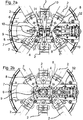
- FIG. 2a shows the forming center 9 and its surroundings of an otherwise according to the generic machine FIG. 1 configured forming machine according to the invention, wherein the forming machine is already scaffolded with relevant tools.
- FIG. 2b shows the machine section FIG. 2a without tools.
- Elements in the FIGS. 2a and 2b and the other figures, the elements of FIG. 1 correspond are marked with correspondingly identical reference numbers.
- Recognizable are in FIG. 2a with their forming tools 10 aligned on a forming center 9 slide assemblies 2 in the forming tools 10 are bending punch, which are front mounted on the plungers 8 of the carriage assemblies 2 and by means of this plunger 8 are axially moved forward and réellebewegbar to perform strokes and return strokes , They are not in guide, but are free forward from the ram 8 of the carriage assemblies 2 from.
- the Schwarzsweg of the punch 10 of a respective slide assembly 2 is thus directionally determined by the positioning and orientation of the associated slide assembly 2.
- a position and Alignment monitoring takes place by means of a positioning control device. This can be done after certain time intervals or continuously.
- FIG. 3 is a possibility of positioning and alignment control of a respective carriage assembly 2 (here the carriage assembly 2a) shown outside of the forming operation of the forming machine.
- an associated as an accessory to the forming machine measuring device 40 is provided, which is temporarily rotatably mounted on a central mandrel in the forming center 9 about a perpendicular to the plane of movement of the forming tool of the respective carriage assembly 2a extending axis of rotation 42 to a in his distal region of the respective forming tool resembling Ausrichtfinger 45 angularly adjustable.
- This alignment finger 45 is along a linear guide 43 orthogonal to the axis of rotation 42 and parallel to the plane of movement of one of the respective carriage unit 2a linearly movable to moving forming tool.
- the alignment finger 45 thus has a rotational degree of freedom determined by the rotatability of the measuring arrangement 40 and an additional degree of translational freedom determined by the mobility along the linear guide 43.
- the adjustment of the alignment finger 45 and its angular orientation is measurable by means of a dial gauge 44, so that the orientation of a respective forming tool can be detected by aligning the alignment finger 45 axially with the carriage assembly 2a in such a way that it assumes the orientation that is on the plunger 8 has properly fixed forming tool 10 or would assume.
- the Ausrichtfinger 45 lies in a different plane than the possibly underlying forming tool 10 so that it does not collide with the carriage assembly 2a at the front end of the ram or a possibly arranged thereon forming tool.
- the positioning and alignment control shown can function without a built-in forming tool of the relevant carriage assembly 2a, since the alignment finger 45 can be oriented so that it points in the direction that the forming tool would occupy. In this case, the angle and displacement data of the alignment finger 45 are detected by means of the dial gauge 44.
- FIG. 4 is a carriage assembly 2 with solid lines in an exact target positioning and alignment shown so that a designated fixed to the plunger 8 forming tool 10 has its assigned workpiece loading point 50 in the forming center 9 has reached with a corresponding forward stroke.
- the carriage assembly 2 is this arranged with its mounting base 10 in a desired base position on the arrangement circle 7 - and aligned by setting angle adjustment by rotation about the axis of rotation 16 so to the forming center 9 that the forming tool 10 (in the example, a punch) his Soll Pakistanddlingsweg along the dash-dotted line 52 can follow the work strokes.
- the axis 52 passes through the axis of rotation 70 and the Maschinennnenbeetzschungsstelle 50th
- the point 55 on the axis 54 marks the point that reaches the forming tool with a specific point at its front end, when the stroke of the incorrectly positioned and aligned carriage assembly 2 corresponds to the stroke of the correctly positioned and aligned carriage assembly 2, with the latter its forming tool 10 has positioned with the appropriate location at the front end to the Maschinen Swissbeetzstoffsstelle.
- the carriage unit 2 can be adjusted by rotating about its by the amount D relative to the target position on the array circuit 7 shifted axis of rotation 16 ', so that the axis 54 with the axis 56 which coincides between the axis of rotation 16 'and the Maschinen Swissbeetzungstician 50 in FIG. 4 extends.
- the positioning deviation D of the carriage assembly on the arrangement circle 7 is not canceled, but this is not necessary in most cases, since the new Schwarzsweg the forming tool 10 along the axis 56 in the vicinity of the Maschinen Swissbeaufschlagungsstelle 50 only negligible from the target Häiolosweg along the axis 52 deviates, what in FIG. 4 is very easy to recognize.
- the detection of the deviation A or a corresponding deviation measure in FIG. 4 can with the referring to FIG. 3 described measures.
- an automatic detection and determination of the required adjustment angle change B by means of suitable measuring and evaluation means is preferred.
- a particularly preferred embodiment of the invention is characterized in that the detection of the position and orientation of the carriage assemblies 2 is carried out optically by image recording by means of at least one camera which detects at least the forming center 9 and its surroundings. By evaluating the image data and comparison with corresponding target data position and alignment error of the carriage units 2 can then be determined in order to finally be able to correct them in the manner already explained.
- FIGS. 5a and 5b A likewise preferred embodiment of a forming machine 1 according to the invention is partially in the FIGS. 5a and 5b shown.
- This embodiment may have some or all features of the embodiments already discussed above and has as an additional feature a split tool holder 4 with a base frame 4 A, which is fixedly connected to the linearly displaceable plunger 8 of the carriage assembly 2 at its front end, and with an Justierrahmen 4B, which is guided on the base frame for carrying out adjusting movements relative to the carriage unit 2 along a rectilinear adjustment path in the example transverse to the longitudinal extension 52 of the carriage assembly 2 in the alignment plane or parallel thereto.
- a split tool holder 4 with a base frame 4 A, which is fixedly connected to the linearly displaceable plunger 8 of the carriage assembly 2 at its front end, and with an Justierrahmen 4B, which is guided on the base frame for carrying out adjusting movements relative to the carriage unit 2 along a rectilinear adjustment path in the example transverse to the longitudinal extension
- the Justierrahmen 4B is shown in a basic position on the base frame 4A, in which it is arranged substantially in alignment with the longitudinal extent 52 of the carriage assembly 2.
- the Justierrahmen 4B is shown displaced out of its basic position along the Justierbahn so that it is laterally offset relative to the carriage unit 2.
- a tool adapter 57 is provided, which for receiving and fixing a respective forming tool (in FIGS. 5a and 5b not shown) is used, so that the forming tool, for example along the horrausrichtachse 53 aligned fixed to the Justierrahmen 4B.
- the Justierrahmen 4B can be fixed in any desired adjustment position on its limited linear Justierbahn means of a clamping screw assembly 60.
- the complementary guide profiles of the base frame and the Justierrahmens of the tool holder may alternatively be shaped so that also obliquely to the longitudinal extent of the carriage assembly running or curved, for example.
- Arc-shaped Justierbahnen present long ago the Justierrahmen is displaceable relative to the base frame of the tool holder.
- the amount of displacement of the Justierrahmens 4B may be limited or fixed for example by one or more lateral stops for the Justierrahmen 4B or a forming tool already provided on the mounting wall 6 or a tool support plate 32 provided for stationary tools.
- Such stops may be formed, for example, by one or more plug pins which are inserted in holes of a hole pattern on the mounting wall or on the tool carrier.
- plug pins with different diameters or / and plug pins with eccentric circumferential contours can be kept in order to be able to use distance variations of the stops.
- the stop pins may be removed after the conversion machine has been installed, i. optionally removed after appropriate adjustment of the or the forming tools. In other cases, such attacks may also remain as one-sided lateral guide means for the respective forming tool on the mounting wall or a plate optionally provided thereon during the subsequent forming processes.
- the displaceability of the Justierrahmens 4B relative to the carriage unit 2 thus represents a further degree of freedom for correcting deviations A of the actual Häzingsweges a to the Justierrahmen 4B intended to be arranged forming tool 10 relative to its desired Häddlingsweg.
- the carriage unit 2 If the associated carriage unit has been moved to a desired base position on the arrangement circle 7 on the mounting wall 6 and fixed there, it is possible for the carriage unit 2 to be about its axis of rotation 16 to turn in a desired alignment position towards the forming center 9. If desired and required, the adjusting frame 4B of the tool holder 4 can then be displaced relative to the carriage assembly 2 along the adjustment path.
- This can be entirely or partially manual or according to a (not shown) development of the embodiment according to FIGS. 5a and 5b be done automatically by means of relevant actuators and under control of a control device. In this way, a forming tool to be arranged on the adjusting frame 4B is thus to be set so that it can perform its forming task precisely in the forming process.
- a relevant positioning control device detects deviations of the actual working movement path of a forming tool 4B intended for the adjusting frame relative to its desired working movement path in the forming center 9, then in a correction mode of the forming machine 1 a correction adjustment of the forming tool can be made using the rotary degree of freedom of the slide unit 2 about its axis of rotation 16 and / or using the degree of freedom of displacement of the JustBEG 4B relative to the carriage unit 2 are performed.
- the actual working movement path of the forming tool can always be monitored for deviations from the desired working movement path by means of the positioning control device, so that a current automatic correction in the described manner by rotating the carriage assembly and / or by displacing the adjustment frame is also possible can.
Landscapes
- Engineering & Computer Science (AREA)
- Mechanical Engineering (AREA)
- Bending Of Plates, Rods, And Pipes (AREA)
Abstract
Die Erfindung betrifft eine Umformmaschine, insbesondere Biegemaschine, umfassend einen Maschinenrahmen mit einer Montagewand (6), wenigstens ein an der Montagewand (6) angeordnetes und wahlweise in verschiedenen Ausrichtpositionen in einer Ausrichtungsebene einstellbares Schlittenaggregat (2) zur Bewegung eines daran vorderseitig abstehend befestigten Umformwerkzeugs (10), insbesondere Biegestempels, in einer Bewegungsebene zu einer vorbestimmten Werkstückbeaufschlagungsstelle (50) in einem Umformzentrum (9), wobei die Anordnung so getroffen ist, dass zur Führung des Umformwerkzeugs (10) während des Umformbetriebs der Maschine kein vom Schlittenaggregat (2) gesonderter Führungskanal in der Bewegungsebene des Umformwerkzeugs (10) vorhanden ist, so dass der Arbeitsbewegungsweg des Umformwerkzeugs (10) in dessen Bewegungsebene richtungsmäßig durch die Positionierung und Ausrichtung des Schlittenaggregates (2) bzw. eines ggf. daran zur Halterung des Umformwerkzeugs (10) vorgesehenen Werkzeughalters (4) festgelegt ist, und eine Positionierkontrolleinrichtung (40) zur Erfassung von Abweichungen des tatsächlichen Ist-Arbeitsbewegungsweges des Umformwerkzeugs (10) von dem vorbestimmten Soll-Arbeitsbewegungsweg im Umformzentrum (9). Verfahren zur Positionskorrektur des Umformwerkzeugs werden auch beschrieben.The invention relates to a forming machine, in particular a bending machine, comprising a machine frame with a mounting wall (6), at least one carriage assembly (2) arranged on the mounting wall (6) and optionally adjustable in different alignment positions in an alignment plane for moving a forming tool mounted thereon (FIG. 10), in particular bending punch, in a plane of movement to a predetermined Werkstückbeaufschlagungsstelle (50) in a forming center (9), wherein the arrangement is such that for guiding the forming tool (10) during the Umformbetriebs the machine no separate from the carriage unit (2) Guide channel in the plane of movement of the forming tool (10) is present, so that the Arbeitsbewegungsweg of the forming tool (10) in the plane of movement directionally by the positioning and orientation of the carriage assembly (2) or optionally provided thereon for holding the forming tool (10) Tool holder (4) is fixed, and a positioning control device (40) for detecting deviations of the actual actual Arbeitsbewegungsweges of the forming tool (10) from the predetermined desired Arbeitsbewegungsweg in the forming center (9). Methods for correcting the position of the forming tool are also described.
Description
Die vorliegende Erfindung betrifft eine Umformmaschine, insbesondere Biegemaschine, umfassend einen Maschinenrahmen mit einer Montagewand und wenigstens ein an der Montagewand angeordnetes und wahlweise in verschiedenen Ausrichtpositionen in einer Ausrichtungsebene einstellbares Schlittenaggregat zur Bewegung eines daran vorderseitig abstehend befestigten Umformwerkzeugs, insbesondere Biegestempels, in einer Bewegungsebene zu einem Werkstücksbeaufschlagungspunkt in einem Umformzentrum.The present invention relates to a forming machine, in particular a bending machine, comprising a machine frame with a mounting wall and at least one arranged on the mounting wall and optionally adjustable in different alignment positions in an alignment sled assembly for moving a front projecting thereon fixed forming tool, in particular punch, in a plane of movement to a Workpiece loading point in a forming center.
Eine Umformmaschine der vorstehend genannten Art ist z.B. in der
Üblicherweise handelt es sich bei den umzuformenden Werkstücken um Blechabschnitte oder Drahtabschnitte von einem Bandmaterial, das von einem Coil abgewickelt wird. Nach dem Umformvorgang werden die umgeformten Werkstücke dann ausgeworfen und gesammelt oder einer weiteren Bearbeitungsstation zugeführt.Usually, the workpieces to be formed are sheet metal sections or wire sections of a strip material which is unwound from a coil. After the forming process, the formed workpieces are then ejected and collected or fed to another processing station.
Zur Erleichterung eines Einrüstvorgangs oder Umrüstvorgangs können die Schlittenaggregate der aus der
Wenngleich die Umformmaschine gemäß der
Zur Lösung dieser Aufgabe wird erfindungsgemäß eine Umformmaschine mit den Merkmalen des Anspruchs 1 sowie ferner ein Verfahren zu deren Betrieb vorgeschlagen.To solve this problem, a forming machine according to the invention with the features of
Die erfindungsgemäße Umformmaschine, bei der es sich um eine Biegemaschine, einen Stanz-/Biegeautomat oder dgl. handeln kann, umfasst
- einen Maschinenrahmen mit einer Montagewand,
- wenigstens ein an der Montagewand angeordnetes und wahlweise in verschiedenen Ausrichtpositionen in einer Ausrichtungsebene einstellbares Schlittenaggregat zur Bewegung eines daran vorderseitig abstehend befestigten Umformwerkzeugs, insbesondere Biegestempels, in einer Bewegungsebene zu einer vorbestimmten Werkstückbeaufschlagungsstelle in einem Umformzentrum, wobei die Anordnung so getroffen ist, dass zur Führung des Umformwerkzeugs während des Umformbetriebs der Maschine kein vom Schlittenaggregat gesonderter Führungskanal in der Bewegungsebene des Umformwerkzeugs zu dessen Führung an einander gegenüberliegenden Seiten vorhanden ist, so dass der Arbeitsbewegungsweg des Umformwerkzeugs in dessen Bewegungsebene richtungsmäßig durch die Positionierung und Ausrichtung des Schlittenaggregates festgelegt ist, und
- eine Positionierkontrolleinrichtung zur Erfassung von Abweichungen des tatsächlichen Ist-Arbeitsbewegungsweges des Umformwerkzeuges von dem vorbestimmten Soll-Arbeitsbewegungsweg im Umformzentrum.
- a machine frame with a mounting wall,
- at least one arranged on the mounting wall and optionally adjustable in different alignment positions in an alignment plane carriage assembly for moving a front projecting thereon fixed forming tool, in particular punch, in a plane of movement to a predetermined Werkstückbeaufschlagungsstelle in a forming center, wherein the arrangement is made such that the leadership the Umformwerkzeugs during Umformbetriebs the machine no separate from the carriage assembly guide channel in the plane of movement of the forming tool to guide it on opposite sides is present, so that the Arbeitsbewegungsweg the forming tool is set in the movement plane directionally by the positioning and orientation of the carriage unit, and
- a positioning control device for detecting deviations of the actual actual working movement path of the forming tool from the predetermined desired working movement path in the forming center.
Bei dem Schlittenaggregat handelt es sich vorzugsweise um ein solches mit elektromotorischem Antrieb, welches numerisch steuerbar ist, also um ein sog. NC-Schlittenaggregat oder NC-Umformaggregat.The carriage unit is preferably one with an electromotive drive which is numerically controllable, that is to say a so-called NC carriage unit or NC forming unit.
Ein Wesensmerkmal der vorliegenden Erfindung ist es, dass die Umformmaschine keine Werkzeugführungsplatte oder Werkzeugplatte mit Führungskanälen in der Bewegungsebene des Umformwerkzeugs aufweist, so dass das Umformwerkzeug bei seinen Hubbewegungen hin zur Werkstückbeaufschlagungsstelle und zurück ausschließlich durch das Schlittenaggregat geführt wird und der Arbeitsbewegungsweg des Umformwerkzeugs in dessen Bewegungsebene somit allein durch die Positionierung und Ausrichtung des Schlittenaggregates festgelegt ist. Das Umformzentrum umfasst den Raumbereich, der von dem Umformwerkzeug bei dessen Arbeitshüben erreicht werden kann. Die Werkstückbeaufschlagungsstelle ist der Ort im Umformzentrum, an dem das Umformwerkzeug bei seinem Arbeitshub mit dem zu bearbeitenden Werkstück in Berührung kommt. Damit das Umformwerkzeug nach dem betreffenden Rüsten der Maschine bei seinen Arbeitshüben möglichst stabil seinem vorbestimmten Arbeitsbewegungsweg folgt, ist ein hinreichend ausgesteiftes Schlittenaggregat vorzusehen, welches eine stabile, reproduzierbare Führung seines Stößels im Umformbetrieb der Umformmaschine bietet. Damit werden die aus dem Stand der Technik bekannten Führungskanäle im Umformzentrum und somit auch die damit ausgestalteten Werkzeugführungsplatten entbehrlich. Dies ist ein wichtiger Ansatzpunkt der Erfindung. Der Verzicht auf die Werkzeugführungsplatte bedeutet nicht nur die Einsparung eines normalerweise aufwändig herzustellenden, kompliziert geformten Elementes sondern eröffnet Freiheiten in der Ausnutzung des Platzes im Umformzentrum. Diese Freiheiten erlauben Vereinfachungen in der Geometrie und Anordnung von Werkzeugelementen und insbesondere auch der Reduzierung der Anzahl von Werkzeugelementen, die für einen jeweiligen Umformprozess zur Umformung eines Werkstücks erforderlich sind. Insbesondere erlauben die größeren geometrischen Freiheiten der Gestaltung des Umformzentrums die Nutzung von Werkzeugnormalien, welche zumindest gruppenweise auf gleich geformten Rohlingen basieren und lediglich an ihren Werkstückbeaufschlagungsenden produktspezifisch in Bezug auf ihre Aufgabe bei dem Umformprozess individualisiert sind.An essential feature of the present invention is that the forming machine has no tool guide plate or tool plate with guide channels in the plane of movement of the forming tool, so that the forming tool is guided in its strokes toward the Werkstückbeaufschlagungsstelle and back exclusively by the carriage assembly and the Arbeitsbewegungsweg the forming tool in its plane of movement thus determined solely by the positioning and orientation of the carriage unit. The forming center comprises the space that can be reached by the forming tool at its working strokes. The Werkstückbeaufschlagungsstelle is the place in the forming center, where the forming tool comes in its working stroke with the workpiece to be machined in touch. In order for the forming tool to follow its predetermined working movement path as stably as possible after the machine has been set up in its working strokes, a sufficiently stiffened carriage assembly is to be provided which provides a stable, reproducible guidance of its tappet in the forming operation of the forming machine. Thus, the known from the prior art guide channels in the forming center and thus the thus designed Tool guide plates dispensable. This is an important starting point of the invention. The absence of the tool guide plate not only means the saving of a complicated to produce complicated, complicated shaped element but also opens up freedom in the use of space in the forming center. These freedoms allow simplifications in the geometry and arrangement of tool elements, and in particular, the reduction in the number of tool elements required for a particular forming process for forming a workpiece. In particular, allow the greater geometric freedom of the design of the Umformzentrums the use of tool standards, which are based at least in groups on the same shaped blanks and are customized only at their Werkstückbeaufschlagungsenden product specific with respect to their task in the forming process.
Der Rückgriff auf solche Werkzeugnormalien erlaubt auch eine weitgehend einheitliche Gestaltung der Ankopplungsmittel zwischen Werkzeug und Werkzeughalter des Stößels. Dies kann in den meisten Fällen zu einer erheblichen Reduzierung der Werkzeugkosten genutzt werden.The recourse to such tool standards also allows a largely uniform design of the coupling means between the tool and tool holder of the plunger. This can be used in most cases to a significant reduction in tooling costs.
Die größeren geometrischen Freiheiten bei der Nutzung des Umformzentrums erlauben auch eine flexiblere Wahl des Arbeitsbewegungsweges des Umformwerkzeugs. Dieser Aspekt hat große Bedeutung im Falle einer erfindungsgemäßen Umformmaschine mit mehreren solchen Schlittenaggregaten mit Umformwerkzeugen. Damit gestaltet sich auch die Planung eines mit der Umformmaschine durchzuführenden Umformprozesses zur Herstellung eines bestimmten Werkstücks flexibler und optimierungsfreundlicher.The greater geometric freedom in using the Umformzentrums also allow a more flexible choice of Arbeitsbewegungsweges the forming tool. This aspect is of great importance in the case of a forming machine according to the invention with several such slide assemblies with forming tools. This also makes the planning of a forming process to be carried out with the forming machine for producing a specific workpiece more flexible and easier to optimize.
Als angebauter Bestandteil der Umformmaschine oder zumindest als gesondert aufzubewahrendes und im Bedarfsfall einsetzbares Zubehör ist die Positionierkontrolleinrichtung als der Umformmaschine zugehörig vorgesehen. Sie ist dazu betreibbar, Abweichungen der Positionierung bzw. Ausrichtung des Schlittenaggregates von einer Soll-Positionierung und -ausrichtung des Schlittenaggregates durch Messung im Bereich des Umformzentrums zu messen oder zu erfassen, so dass mittels der Positionierkontrolleinrichtung festgestellt werden kann, ob das Umformwerkzeug im Umformzentrum und insbesondere an oder in der unmittelbaren Umgebung der vorbestimmten Werkstückbeaufschlagungsstelle von seinem vorbestimmten Soll-Arbeitsbewegungsweg abweicht. Wird eine solche Abweichung festgestellt, so kann das Messergebnis dazu benutzt werden, das Umformwerkzeug hinsichtlich seiner Positionierung und/oder Ausrichtung nachzustellen, so dass die Abweichung zumindest verringert wird. Die Positionierkontrolleinrichtung ist auch ein nützliches Hilfsmittel bei der Ein- oder Umrüstung der Umformmaschine und zwar zur Kontrolle der korrekten Positionierung und Ausrichtung des Schlittenaggregates.As an attached component of the forming machine or at least as a separately stored and if necessary usable accessory, the positioning control device is provided as belonging to the forming machine. It is operable to deviations of the positioning or alignment of the carriage assembly from a desired positioning and alignment of the To measure or detect carriage assemblies by measuring in the region of the Umformzentrums so that it can be determined by means of the Positionierkontrolleinrichtung whether the forming tool deviates from its predetermined desired Arbeitsbewegungsweg in Umformzentrum and in particular on or in the immediate vicinity of the predetermined Werkstückbeaufschlagungsstelle. If such a deviation is found, then the measurement result can be used to adjust the forming tool with respect to its positioning and / or orientation, so that the deviation is at least reduced. The Positionierkontrolleinrichtung is also a useful tool when installing or retrofitting the forming machine and that to control the correct positioning and alignment of the carriage assembly.
Vorzugsweise hat das Schlittenaggregat einen Montagesockel mittels welchem es in einer gewünschten Basisposition an der Montageplatte fixierbar ist, wobei das Schlittenaggregat ferner in der jeweiligen Basisposition relativ zu dem Montagesockel um eine senkrecht zur Ausrichtungsebene verlaufende Drehachse drehbar ist, um einen jeweiligen Stellwinkel des Umformwerkzeugs zu dessen Ausrichtung relativ zur Werkstückbeaufschlagungsstelle einzustellen. Eine solche Positionier- und Verstellmöglichkeit eines Schlittenaggregates ist seiner Art nach beispielsweise aus der bereits genannten
Wie an sich aus der bereits angesprochenen
Wie oben bereits angedeutet, kann die Umformmaschine gemäß einer bevorzugten Ausführungsform in einem Korrekturmodus betreibbar sein, in dem eine mittels der Positionierkontrolleinrichtung erfasste Abweichung des Ist-Arbeitsbewegungsweges des Umformwerkzeugs relativ zu dem Soll-Arbeitsbewegungsweg durch Änderung der Ausrichtung des Schlittenaggregates verringerbar oder kompensierbar ist. Dies kann mit hinreichender Genauigkeit oft allein durch Drehen des Schlittenaggregates um die senkrecht zur Bewegungsebene des Umformwerkzeugs verlaufende Drehachse erfolgen. Die Erfassung eines Fehlers des Arbeitsbewegungsweges sollte stets durch Messung im Umformzentrum nahe der Stelle erfolgen, an der das Umformwerkzeug mit einem betreffenden Werkstück in Kontakt geraten soll. Hierdurch wird erreicht, dass zumindest in dem Raumbereich, in dem es auf eine möglichst genaue Einhaltung des Soll-Arbeitsbewegungsweges des Werkzeugs im Umformzentrum ankommt, die Abweichungen mit einfachen Mitteln korrigiert werden können.As already indicated above, according to a preferred embodiment, the forming machine can be operated in a correction mode in which a deviation of the actual working movement path of the forming tool relative to the desired working movement path detected by the positioning control device can be reduced or compensated by changing the orientation of the carriage assembly. This can be done with sufficient accuracy often alone by rotating the carriage assembly about the axis of rotation perpendicular to the plane of movement of the forming tool. The detection of an error of the working movement path should always be made by measurement in the forming center near the point where the forming tool should come into contact with a relevant workpiece. This ensures that at least in the space area in which it depends on the most accurate compliance with the target Arbeitsbewegungsweges of the tool in the forming center, the deviations can be corrected with simple means.
Die Korrektur der Ausrichtung des Schlittenaggregates kann automatisch gesteuert mittels der dazu vorgesehenen steuerbaren Stellantriebsmittel erfolgen, insbesondere mittels des steuerbaren Drehantriebs. Eine diesbezüglich automatische laufende Überwachung der Einhaltung des Soll-Arbeitsbewegungsweges des Umformwerkzeuges im Umformzentrum ist gemäß einer weiteren bevorzugten Ausführungsform der Erfindung möglich. Geeignete Sensoren, wie etwa Linearencoder, magnetische Abstandssensoren oder induktive Abstandssensoren oder dgl., können zur Erfassung der Abweichung von Ist-Positionen des Umformwerkzeuges von Soll-Positionen zum Einsatz kommen.The correction of the orientation of the carriage assembly can be controlled automatically by means of the provided controllable actuator means, in particular by means of the controllable rotary drive. An automatic ongoing monitoring of compliance with the desired working movement path of the forming tool in the forming center is possible in accordance with a further preferred embodiment of the invention. Suitable sensors, such as linear encoders, magnetic distance sensors or inductive distance sensors or the like, can be used to detect the deviation of actual positions of the forming tool from desired positions.
Eine besonders bevorzugte Ausführungsform der Erfindung sieht vor, dass die Positionierkontrolleinrichtung eine optische Positionserfassungseinrichtung, vorzugsweise Bilderfassungseinrichtung zur optischen, insbesondere bildweisen Erfassung von Ist-Positionen des Schlittenaggregates oder/und des Umformwerkzeugs umfasst, wobei ferner Auswertemittel zur Auswertung zum Zwecke der Erfassung von Abweichungen von zueinander zugeordneten Ist-Positionsdaten und Soll-Positionsdaten als Basis für eine insbesondere automatische Positionierungs- und Ausrichtungskorrektur des Schlittenaggregates vorgesehen sind. Die optische Positionserfassungseinrichtung kann z.B. eine oder mehrere Fotozellen oder dergleichen als Sensoren aufweisen. In ihrer Ausgestaltung als Bilderfassungseinrichtung kann sie beispielsweise einen oder mehrere Kamerasensoren oder Kameras aufweisen. Gemäß einer Variante könnte die Bilderfassungseinrichtung Standbilder im Sinne von Fotografien aufnehmen. Gemäß einer weiteren Variante könnte die Bilderfassungseinrichtung dazu bestimmt und ausgestaltet sein, Bewegbilder im Sinne von Filmsequenzen aufzunehmen, um den Arbeitsbewegungsweg des Umformwerkzeugs beispielsweise während seiner Bewegung aufzunehmen. Die Soll-Positionsdaten können in einem Speicher vorgehalten sein. Vorzugsweise werden auch diese Soll-Positionsdaten auf der Basis von Bilddaten einer betreffenden Bilderfassungseinrichtung erzeugt. Hierzu kann beispielsweise ein Referenzbild oder eine Referenzfilmsequenz insbesondere vom Umformzentrum der ursprünglich präzise eingerüsteten Maschine aufgenommen werden, wobei die Bilddaten nach entsprechender Auswertung dann als Soll-Positionsdaten bereitgestellt werden können. Alternativ können die Soll-Positionsdaten auch computergenerierte Daten sein, mit denen die optisch erfassten Ist-Positionsdaten automatisch verglichen werden.A particularly preferred embodiment of the invention provides that the positioning control device comprises an optical position detection device, preferably image detection device for optical, in particular image-wise detection of actual positions of the carriage assembly and / or the forming tool, further comprising evaluation means for evaluation for the purpose of detecting deviations from each other assigned actual position data and target position data are provided as a basis for a particular automatic positioning and alignment correction of the carriage unit. The optical position detection device may, for example, have one or more photocells or the like as sensors. In its embodiment as an image capture device, it may have, for example, one or more camera sensors or cameras. According to a variant, the image capture device could capture still images in the sense of photographs. According to a further variant, the image capture device could be designed and configured to record moving images in the sense of film sequences in order to record the working movement path of the forming tool during its movement, for example. The desired position data can be stored in a memory. Preferably, these desired position data are also generated on the basis of image data of a respective image capture device. For this purpose, for example, a reference image or a reference movie sequence in particular be absorbed by the forming center of the originally precisely equipped machine, the image data can then be provided after appropriate evaluation as desired position data. Alternatively, the desired position data may also be computer-generated data with which the optically detected actual position data are automatically compared.
Der Überwachungsprozess der Ist-Situation kann beispielsweise regelmäßig nach bestimmten Zeitabständen automatisch erfolgen. Andererseits besteht auch die Möglichkeit den Überwachungsprozess kontinuierlich insbesondere auch während eines Umformprozesses, also während der normalen Arbeitsweise der Umformmaschine ablaufen zu lassen.The monitoring process of the actual situation can, for example, be carried out automatically at regular intervals after certain time intervals. On the other hand, it is also possible to run the monitoring process continuously, in particular during a forming process, ie during the normal operation of the forming machine.
Bei Feststellung einer nicht mehr zu tolerierenden Abweichung des Ist-Arbeitsbewegungsweges vom Soll-Arbeitsbewegungsweg im Umformzentrum kann dann ein automatischer Korrekturvorgang erfolgen, in dem die Umformmaschine beispielsweise vorübergehend in einen Korrekturmodus übergeht, um die Abweichung zu verringern bzw. zu kompensieren.If a deviation of the actual working movement path from the desired working movement path in the forming center that can no longer be tolerated is detected, then an automatic correction process can take place in which the forming machine, for example, temporarily changes to a correction mode in order to reduce or compensate for the deviation.
Eine weitere bevorzugte Ausführungsform einer Umformmaschine nach der Erfindung ist im Anspruch 4 dargelegt, wobei Ausgestaltungen dieser weiteren Ausführungsform in den auf Anspruch 4 rückbezogenen Ansprüchen, insbesondere auch in den Ansprüchen 13 - 15 genannt sindA further preferred embodiment of a forming machine according to the invention is set forth in
Gegenstand der Erfindung ist auch ein Verfahren zur Positionskorrektur des Schlittenaggregates einer Umformmaschine nach Anspruch 2. Das Verfahren umfasst die Schritte:
- Erfassen einer Abweichung des Ist-Arbeitsbewegungsweges des Umformwerkzeugs von einem vorbestimmten Soll-Arbeitsbewegungsweg im Umformzentrum und
- Verdrehen des Schlittenaggregates um die Drehachse, so dass die Abweichung zumindest verringert wird.
- Detecting a deviation of the actual working movement path of the forming tool from a predetermined target working movement path in the forming center and
- Turning the carriage assembly about the axis of rotation, so that the deviation is at least reduced.
Eine bevorzugte Ausführungsform des Verfahrens geht davon aus, dass geringe Positionsabweichungen des Schlittenaggregates allein durch Änderung des Stellwinkels durch Verdrehen des Schlittenaggregates soweit korrigierbar sind, dass sie sich nach der Korrektur an der Werkzeugbeaufschlagungsstelle im Umformzentrum nicht relevant auswirken. Das Nachstellen des Stellwinkels durch Verdrehen des Schlittenaggregates um die Drehachse kann bei hinreichender Auflösung des verwendeten steuerbaren Drehantriebs auf einfache Weise präzise erfolgen.A preferred embodiment of the method is based on the fact that small position deviations of the carriage assembly can be corrected by changing the adjustment angle by turning the carriage unit so far that they do not have any relevance after the correction at the tool loading point in the forming center. The adjustment of the adjustment angle by rotating the carriage assembly about the axis of rotation can be done precisely with sufficient resolution of the controllable rotary drive used in a simple manner.
Gegenstand der Erfindung ist auch ein Verfahren nach Anspruch 19 zur Positionskorrektur des Umformwerkzeugs einer Umformmaschine nach Anspruch 4, umfassend die Schritte:
- Erfassen einer Abweichung (A) des Ist-Arbeitsbewegungsweges des Umformwerkzeugs von einem vorbestimmten Soll-Arbeitsbewegungsweg im Umformzentrum (9) und
- Verschieben des Justierrahmens (4B) längst der Justierbahn, so dass die Abweichung (A) zumindest verringert wird.
- Detecting a deviation (A) of the actual working movement path of the forming tool from a predetermined desired working movement path in the forming center (9) and
- Moving the Justierrahmens (4B) long the Justierbahn, so that the deviation (A) is at least reduced.
Die Verfahren nach Anspruch 18 und Anspruch 19 können kombiniert werden, so dass zur Verringerung der Abweichung (A) sowohl das Schlittenaggregat um seine Drehachse verdreht wird, als auch der Justierrahmen längs der Justierbahn verschoben wird.The method of claim 18 and
Vorzugsweise umfasst der Schritt des Erfassens einer Abweichung des Ist-Arbeitsbewegungsweges des Umformwerkzeugs von einem vorbestimmten Soll-Arbeitsbewegungsweg das optische Erfassen, insbesondere bildweise Erfassen von Ist-Positionen des Schlittenaggregates oder/und des Umformwerkzeugs mittels einer optischen Positionserfassungseinrichtung, vorzugsweise Bilderfassungseinrichtung - und das Vergleichen der dabei ermittelten Daten mit Referenzdaten von zugeordneten Soll-Positionen des Schlittenaggregates oder/und des Umformwerkzeugs.Preferably, the step of detecting a deviation of the actual working movement path of the forming tool from a predetermined desired working movement path comprises optically detecting, in particular imagewise detecting actual positions of the carriage assembly and / or the forming tool by means of an optical position detection device, preferably image capture device - and comparing the thereby determined data with reference data of assigned desired positions of the carriage assembly and / or the forming tool.
Das Erfassen von Ist-Positionen des Umformwerkzeugs setzt nicht voraus, dass das Umformwerkzeug tatsächlich während des Messvorgangs eingebaut ist. Es kann beispielsweise auch ein Element einer Messeinrichtung, beispielsweise ein mit Markierungen ausgestattetes Element anstelle des Umformwerkzeugs in dessen Position relativ zum Schlittenaggregat angeordnet sein.The detection of actual positions of the forming tool does not require that the forming tool is actually installed during the measuring process. For example, it is also possible to arrange an element of a measuring device, for example an element provided with markings, instead of the forming tool in its position relative to the carriage unit.
Möglichkeiten der Vorgehensweise des Erfassens von geometrischen Abweichungen von Soll-Positionen, wie sie auch bei dem vorliegenden Verfahren eingesetzt werden können, wurden vorstehend bereits im Zusammenhang mit der Umformmaschine erwähnt.Possibilities of the procedure of detecting geometric deviations from desired positions, as they can also be used in the present method, have already been mentioned above in connection with the forming machine.
Vorzugsweise erfolgt die Einstellung oder Nachstellung des Stellwinkels des Schlittenaggregates durch Verdrehen automatisch in Abhängigkeit von der ermittelten Abweichung des Ist-Arbeitsbewegungsweges des Umformwerkzeugs von dem vorbestimmten Soll-Arbeitsbewegungsweg mittels eines steuerbaren Drehantriebs.Preferably, the setting or adjustment of the adjustment angle of the carriage assembly is carried out by turning automatically in response to the determined deviation of the actual working movement path of the forming tool from the predetermined desired Arbeitsbewegungsweg means of a controllable rotary drive.
Der Schritt des Erfassens einer Abweichung des Ist-Arbeitsbewegungsweges des Umformwerkzeugs von einem vorbestimmten Soll-Arbeitsbewegungsweg kann gemäß einer Verfahrensvariante laufend automatisch, vorzugsweise auch während des Umformbetriebs der Umformmaschine erfolgen.The step of detecting a deviation of the actual working movement path of the forming tool from a predetermined desired working movement path can be carried out continuously automatically according to a variant of the method, preferably also during the forming operation of the forming machine.
Durch die Möglichkeit der einfachen Überwachung und Korrektur von Abweichungen des Umformwerkzeugs von seinem vorbestimmten Soll-Arbeitsweg kann ein weitgehend störungsfreier und dauerhafter Betrieb der Umformmaschine unter Verzicht auf Werkzeugführungsplatten bzw. Werkzeugplatten, wie sie aus dem Stand der Technik bekannt sind, gewährleistet werden. Damit eröffnen sich Möglichkeiten einer optimierten Ausnutzung des Platzes im Umformzentrum, also des Bereichs, in dem die Werkstückumformung stattfindet. Damit einhergehend können einfacher geformte Werkzeuge als bisher zum Einsatz kommen, insbesondere Werkzeuge, die auf standardisierten Grundformen basieren. Auch ist die Anzahl insbesondere nicht bewegter Werkzeugelemente im Umformzentrum bei vielen Umformprozessen deutlich geringer zu halten, als dies nach dem Stand der Technik für gleiche Umformaufgaben möglich war.Due to the possibility of simple monitoring and correction of deviations of the forming tool from its predetermined desired working path, a largely trouble-free and permanent operation of the forming machine waiving tool guide plates or tool plates, as they are known from the prior art, guaranteed. This opens up opportunities for optimized utilization of the space in the forming center, ie the area in which the workpiece is formed. This can be simpler tools than before are used, in particular tools based on standardized basic forms. Also, the number of particular non-moving tool elements in the forming center in many forming processes to keep significantly lower than was possible in the prior art for the same forming tasks.
Die Erfindung wird nachstehend unter Bezugnahme auf die Figuren näher erläutert.
Figur 1- zeigt in einer Frontansicht eine gattungsgemäße Umformmaschine nach dem Stand der Technik, wie sie in
der EP 2 641 669 A1 Figur 2a- zeigt in Frontansicht einen das Umformzentrum umfassenden Bereich einer Umformmaschine nach der Erfindung mit Umformwerkzeugen.
- Figur 2b
- zeigt den
Maschinenbereich aus Figur 2a in entsprechender Perspektive, jedoch ohne Umformwerkzeuge. Figur 3- zeigt in einer Frontansicht ein Detail einer Umformmaschine nach der Erfindung, nämlich ein Umformzentrum mit darauf ausgerichteten Schlittenaggregaten und mit einer Positionierkontrolleinrichtung zur Erfassung von Abweichungen des tatsächlichen IstArbeitsbewegungsweges eines Umformwerkzeugs von dem vorbestimmten Soll-Arbeitsbewegungsweg des Umformwerkzeugs an einer vorbestimmten Stelle im Umformzentrum.
Figur 4- zeigt zur Erläuterung einer Korrekturoperation ein Detail einer Umformmaschine nach der Erfindung in Frontansicht.
- Figuren 5a und 5b
- zeigen in einer perspektivischen Ausschnittsdarstellung ein weiteres Ausführungsbeispiels der Erfindung mit einem Werkzeughalter, welcher einen Basisrahmen und einen relativ dazu verschiebbaren Justierrahmen aufweist, wobei in
Figur 5a der Justierrahmen in Flucht zur Längserstreckung des zugeordneten Schlittenaggregates in einer Grundstellung dargestellt ist, wohingegen er inFigur 5b seitlich aus dieser Grundstellung heraus verschoben dargestellt ist.
- FIG. 1
- shows a front view of a generic forming machine according to the prior art, as shown in the
EP 2 641 669 A1 - FIG. 2a
- shows a front view of the forming center comprehensive range of a forming machine according to the invention with forming tools.
- FIG. 2b
- shows the machine area
FIG. 2a in the same perspective, but without forming tools. - FIG. 3
- shows a front view of a detail of a forming machine according to the invention, namely a forming center with aligned slide assemblies and with a positioning control device for detecting deviations of the actual IstArbeitsbewegungsweges a forming tool from the predetermined target Arbeitsbewegungsweg the forming tool at a predetermined location in the forming center.
- FIG. 4
- shows a detail of a forming machine according to the invention in front view to explain a correction operation.
- FIGS. 5a and 5b
- show in a perspective cutaway view of another embodiment of the invention with a tool holder, which has a base frame and a relative thereto slidable Justierrahmen, wherein in
FIG. 5a the Justierrahmen in alignment with the longitudinal extension of the associated Slide unit is shown in a basic position, whereas he inFIG. 5b is shown displaced laterally out of this basic position.
Bei der in
In dem Umformzentrum 9 weist die bekannte gattungsgemäße Umformmaschine 1 eine Werkzeugführungsplatte 13 auf, die mit Führungskanälen 15 für die Umformwerkzeuge 10 ausgestattet ist. Die Führungskanäle liegen in einer Ausrichtebene der Schlittenaggregate 2, die parallel zu der Montagewand 6 verläuft. Die Umformwerkzeuge, beispielsweise Biegestempel 10, sind in den Führungskanälen 15 aufgenommen und darin stabil zur Ausführung ihrer Arbeitshübe in Richtung Umformzentrum 9 und zurück geführt, so dass sie auf ihrem vorbestimmtem Soll-Arbeitsbewegungsweg bei ihren Arbeitshüben während eines Umformprozesses bei der Bearbeitung eines umzuformenden Werkstückes im Umformzentrum 9 verbleiben. Wie bereits eingangs erwähnt, sind derartige Werkzeugführungsplatten 13 relativ komplex geformt und für den jeweiligen speziellen anstehenden Umformprozess individuell ausgestaltet.In the forming
Es ist ersichtlich, dass beim Einrüsten der Umformmaschine 1 für eine bestimmte Umformaufgabe die Schlittenaggregate 2 exakt so positioniert - und ausgerichtet werden müssen, dass sie die Umformwerkzeuge 10 längs der Zwangsführungen durch die Führungskanäle 15 weitestgehend klemmfrei vor- und zurückbewegen können.It can be seen that when installing the forming
Zur Erleichterung eines solchen Einrüstvorgangs können die Schlittenaggregate 2 auf dem Anordnungskreis 7 automatisch in verschiedene Basispositionen verschoben werden. Hierzu weisen sie Montagesockel 17 auf, die mit Eingriffsmitteln durch eine den Anordnungskreis 7 definierende Kreisnut hindurch die Montagewand 6 hintergreifen und in einer jeweiligen Basisposition an der Montagewand 6 fixierbar sind. Zur Bewegung der Schlittenaggregate 2 entlang des Anordnungskreises 7 ist ein rückseitig der Montagewand 6 angeordneter, steuerbarer Stellantrieb (nicht gezeigt) vorgesehen.To facilitate such an installation process, the
Jedes Schlittenaggregat 2 ist um eine senkrecht zur Bewegungsebene des zugehörigen Umformwerkzeugs stehende Drehachse 16 relativ zu ihrem Montagesockel 17 drehbar, so dass eine Stellwinkeleinstellung des betreffenden Umformwerkzeugs 10 ausgehend von einer jeweiligen Basispositionierung des Schlittenaggregates 2 auf dem Anordnungskreis 7 möglich ist. (Dies ist für einige Schlittenaggregate 2 in
Abgesehen von der Anordnung und Verwendung einer Werkzeugführungsplatte 13 kann eine Umformmaschine gemäß der vorliegenden Erfindung die vorstehend erwähnten Merkmale der Umformmaschine gemäß
Zusätzlich zu den bewegten Umformwerkzeugen 10 (Biegeschlitten 10) sind in dem Umformzentrum 9 noch feststehende Umformwerkzeuge 31 vorgesehen. Diese feststehenden Werkzeuge 31 sind auf einem rückwärtigen standardisierten Werkzeugträger 32 befestigt, der ein vorgegebenes Nuten- und Gewinderaster zur Befestigung von feststehenden Werkzeugelementen 31 aufweist. Ein solcher Werkzeugträger 32 ist in
In
In
Mit gestrichelten Linien ist in
Zur Korrektur des Positions- und Ausrichtungsfehlers, also der Abweichung A, kann das Schlittenaggregat 2 durch Drehen um seine um den Betrag D gegenüber der Soll-Lage auf dem Anordnungskreis 7 verschobene Drehachse 16' verstellt werden, so dass die Achse 54 mit der Achse 56 zusammenfällt, welche sich zwischen der Drehachse 16' und dem Werkstückbeaufschlagungspunkt 50 in
Die Erfassung der Abweichung A oder eines damit korrespondierenden Abweichungsmaßes in
Eine besonders bevorzugte Ausführungsform der Erfindung ist dadurch gekennzeichnet, dass die Erfassung der Position und Ausrichtung der Schlittenaggregate 2 optisch durch Bildaufnahme mittels wenigstens einer Kamera erfolgt, die zumindest das Umformzentrum 9 und seine Umgebung erfasst. Durch Auswertung der Bilddaten und Vergleich mit entsprechenden Soll-Daten können dann Positions- und Ausrichtfehler der Schlittenaggregate 2 festgestellt werden, um sie schließlich in der schon erläuterten Weise korrigieren zu können.A particularly preferred embodiment of the invention is characterized in that the detection of the position and orientation of the
Ein ebenfalls bevorzugtes Ausführungsbeispiel einer Umformmaschine 1 nach der Erfindung ist ausschnittsweise in den
Zur Führung des Justierrahmens 4B an dem Basisrahmen 4A des Werkzeughalters 4 weisen der Basisrahmen wir A und der Justierrahmen 4B einander komplementäre Führungsprofile 58,59 auf. Die Justierrahmen 4B kann in jeder gewünschten Justierstellung auf seiner begrenzten linearen Justierbahn mittels einer Klemmschraubenanordnung 60 fixiert werden.For guiding the
Im Beispielsfall der
Das Maß der Verschiebung des Justierrahmens 4B kann beispielsweise durch einen oder mehrere seitliche Anschläge für den Justierrahmen 4B oder ein daran bereits vorgesehenen Umformwerkzeug an der Montagewand 6 oder einer daran vorgesehenen Werkzeugträgerplatte 32 für unbewegte Werkzeuge begrenzt bzw. festgelegt sein. Solche Anschläge können beispielsweise von einem oder mehreren Steckstiften gebildet sein, die in Löchern eines Lochrasters an der Montagewand bzw. an dem Werkzeugträger eingesteckt sind. Es können hierzu Steckstifte mit unterschiedlichen Durchmessern oder/und Steckstifte mit exzentrischen Umfangskonturen vorgehalten sein, um Abstandsvariationen der Anschläge nutzen zu können. Die Anschlagstifte können nach dem Einrüsten der Umformmaschine, d.h. nach entsprechender Einstellung des oder der Umformwerkzeuge gegebenenfalls entfernt werden. In anderen Fällen können solche Anschläge auch als einseitige seitliche Führungsmittel für das betreffende Umformwerkzeug an der Montagewand oder einer daran gegebenenfalls vorgesehenen Platte auch während der späteren Umformprozesse verbleiben.The amount of displacement of the
Die Verschiebbarkeit des Justierrahmens 4B relativ zu dem Schlittenaggregat 2 stellt somit einen weiteren Freiheitsgrad zur Korrektur von Abweichungen A des Ist-Arbeitsbewegungsweges eines an dem Justierrahmen 4B bestimmungsgemäß anzuordnenden Umformwerkzeugs 10 relativ zu dessen Soll-Arbeitsbewegungsweg dar.The displaceability of the
Ist das zugeordnete Schlittenaggregat in eine gewünschte Basisposition auf dem Anordnungskreis 7 an der Montagewand 6 bewegt- und dort fixiert worden, besteht die Möglichkeit das Schlittenaggregat 2 um seine Drehachse 16 in eine gewünschte Ausrichtstellung hin zu dem Umformzentrum 9 zu drehen. Falls gewünscht und erforderlich kann dann noch der Justierrahmen 4B des Werkzeughalters 4 relativ zu dem Schlittenaggregat 2 längs der Justierbahn verschoben werden. Dies kann insgesamt oder teilweise manuell oder gemäß einer (nicht gezeigten) Weiterbildung des Ausführungsbeispiels gemäß
Sollte eine betreffende Positionierkontrolleinrichtung Abweichungen des Ist-Arbeitsbewegungsweges eines an dem Justierrahmen 4B bestimmungsgemäß angeordneten Umformwerkzeugs relativ zu dessen Soll-Arbeitsbewegungsweg im Umformzentrum 9 feststellen, so kann in einem Korrekturmodus der Umformmaschine 1 eine Korrektureinstellung des Umformwerkzeugs unter Nutzung des Drehfreiheitsgrades des Schlittenaggregates 2 um dessen Drehachse 16 oder/und unter Nutzung des Verschiebefreiheitsgrades des Justierrahmens 4B relativ zu dem Schlittenaggregat 2 durchgeführt werden.If a relevant positioning control device detects deviations of the actual working movement path of a forming
Der Ist-Arbeitsbewegungsweg des Umformwerkzeugs kann gemäß einer Variante der Erfindung stets mittels der Positionierkontrolleinrichtung auf Abweichungen vom Soll-Arbeitsbewegungsweg überwacht werden, so dass auch eine laufende bedarfsweise automatische Korrektur in der geschilderten Weise durch Drehen des Schlittenaggregates oder/und durch Verschieben des Justierrahmens möglich sein kann.According to a variant of the invention, the actual working movement path of the forming tool can always be monitored for deviations from the desired working movement path by means of the positioning control device, so that a current automatic correction in the described manner by rotating the carriage assembly and / or by displacing the adjustment frame is also possible can.
Der Möglichkeit der Einstellung eines Umformwerkzeuges durch Verschieben eines betreffenden Schlittenaggregates längs einer Führung an der Montagewand in eine Basisposition, durch Drehen der Schlittenaggregates um eine Drehachse zur Wahl eines Stellwinkels und durch Verschieben eines betreffenden Justierrahmens eines Werkzeughalters längs einer Justierbahn relativ zu dem Schlittenaggregat in der oben erläuterten Weise kann eigenständige erfinderische Bedeutung auch in der Anwendung bei gattungsgemäßen Umformmaschinen zukommen, also auch bei Umformmaschinen mit Führungskanälen für Umformwerkzeuge im Umformzentrum gemäß
Claims (20)
Priority Applications (1)
| Application Number | Priority Date | Filing Date | Title |
|---|---|---|---|
| PL17150968T PL3219406T3 (en) | 2016-03-18 | 2017-01-11 | Bending machine and position correction method for the slide of such a forming machine |
Applications Claiming Priority (1)
| Application Number | Priority Date | Filing Date | Title |
|---|---|---|---|
| DE102016204572.5A DE102016204572A1 (en) | 2016-03-18 | 2016-03-18 | Forming machine and method for correcting the position of the carriage assembly of such a forming machine |
Publications (2)
| Publication Number | Publication Date |
|---|---|
| EP3219406A1 true EP3219406A1 (en) | 2017-09-20 |
| EP3219406B1 EP3219406B1 (en) | 2018-12-12 |
Family
ID=57838179
Family Applications (1)
| Application Number | Title | Priority Date | Filing Date |
|---|---|---|---|
| EP17150968.0A Active EP3219406B1 (en) | 2016-03-18 | 2017-01-11 | Bending machine and position correction method for the slide of such a forming machine |
Country Status (4)
| Country | Link |
|---|---|
| EP (1) | EP3219406B1 (en) |
| DE (1) | DE102016204572A1 (en) |
| ES (1) | ES2708680T3 (en) |
| PL (1) | PL3219406T3 (en) |
Cited By (2)
| Publication number | Priority date | Publication date | Assignee | Title |
|---|---|---|---|---|
| CN109590733A (en) * | 2018-12-17 | 2019-04-09 | 苏州市全力自动化科技有限公司 | Full automatic car accessory contact pin bending detection machine |
| EP3620242A1 (en) * | 2018-09-05 | 2020-03-11 | BLM S.p.A. | Machine for the working of tubes provided with an optical sensor for measuring the forward displacement of the tube being worked and/or the rotational displacement of the same about the longitudinal axis thereof |
Families Citing this family (1)
| Publication number | Priority date | Publication date | Assignee | Title |
|---|---|---|---|---|
| DE102018217209A1 (en) * | 2018-10-09 | 2020-04-09 | Otto Bihler Handels-Beteiligungs-Gmbh | Tool module for a progressive tool system |
Citations (4)
| Publication number | Priority date | Publication date | Assignee | Title |
|---|---|---|---|---|
| US20110214467A1 (en) * | 2010-03-03 | 2011-09-08 | Wafios Ag | Method and apparatus for production of helical springs by spring winding |
| EP2641669A1 (en) | 2012-03-23 | 2013-09-25 | Otto Bihler Handels-Beteiligungs-GmbH | Shaping machine, in particular bending machine and method for reconfigurating such a shaping machine |
| DE102014206603B3 (en) * | 2014-04-04 | 2015-09-03 | Wafios Ag | Method and spring coiling machine for producing coil springs by spring winds |
| CN205020709U (en) * | 2015-09-29 | 2016-02-10 | 建科机械(天津)股份有限公司 | Crooked stirrup and mechanism of welding stirrup on square steel reinforcement cage owner muscle |
Family Cites Families (3)
| Publication number | Priority date | Publication date | Assignee | Title |
|---|---|---|---|---|
| DE102007031514A1 (en) * | 2007-07-06 | 2009-01-08 | Wafios Ag | Wire forming machine |
| DE102013207028B3 (en) * | 2013-04-18 | 2014-06-26 | Wafios Ag | Spring coiling machine with adjustable cutting device |
| DE102015208350B3 (en) * | 2015-05-06 | 2016-08-25 | Wafios Aktiengesellschaft | Process for the production of molded parts and forming machine for carrying out the method |
-
2016
- 2016-03-18 DE DE102016204572.5A patent/DE102016204572A1/en not_active Withdrawn
-
2017
- 2017-01-11 PL PL17150968T patent/PL3219406T3/en unknown
- 2017-01-11 EP EP17150968.0A patent/EP3219406B1/en active Active
- 2017-01-11 ES ES17150968T patent/ES2708680T3/en active Active
Patent Citations (4)
| Publication number | Priority date | Publication date | Assignee | Title |
|---|---|---|---|---|
| US20110214467A1 (en) * | 2010-03-03 | 2011-09-08 | Wafios Ag | Method and apparatus for production of helical springs by spring winding |
| EP2641669A1 (en) | 2012-03-23 | 2013-09-25 | Otto Bihler Handels-Beteiligungs-GmbH | Shaping machine, in particular bending machine and method for reconfigurating such a shaping machine |
| DE102014206603B3 (en) * | 2014-04-04 | 2015-09-03 | Wafios Ag | Method and spring coiling machine for producing coil springs by spring winds |
| CN205020709U (en) * | 2015-09-29 | 2016-02-10 | 建科机械(天津)股份有限公司 | Crooked stirrup and mechanism of welding stirrup on square steel reinforcement cage owner muscle |
Cited By (2)
| Publication number | Priority date | Publication date | Assignee | Title |
|---|---|---|---|---|
| EP3620242A1 (en) * | 2018-09-05 | 2020-03-11 | BLM S.p.A. | Machine for the working of tubes provided with an optical sensor for measuring the forward displacement of the tube being worked and/or the rotational displacement of the same about the longitudinal axis thereof |
| CN109590733A (en) * | 2018-12-17 | 2019-04-09 | 苏州市全力自动化科技有限公司 | Full automatic car accessory contact pin bending detection machine |
Also Published As
| Publication number | Publication date |
|---|---|
| EP3219406B1 (en) | 2018-12-12 |
| DE102016204572A1 (en) | 2017-09-21 |
| PL3219406T3 (en) | 2019-05-31 |
| ES2708680T3 (en) | 2019-04-10 |
Similar Documents
| Publication | Publication Date | Title |
|---|---|---|
| EP2756893B1 (en) | Apparatus for processing a material, in particular a shaping machine | |
| EP1761357B1 (en) | Pressure welding machine and pressure welding method | |
| EP3308887B1 (en) | Clamping unit | |
| WO2015019285A1 (en) | Bending press | |
| EP3027332B1 (en) | Bending tool system | |
| EP3219406B1 (en) | Bending machine and position correction method for the slide of such a forming machine | |
| EP0577068A1 (en) | Bending machine | |
| DE102018000022A1 (en) | Method for straightening concentricity or gradients on elongate workpieces, as well as measuring device, straightening machine and straightening system | |
| DE202014105434U1 (en) | Pressure welding apparatus | |
| EP2165784B1 (en) | Device and method for automatically centring die holders of a stamping machine | |
| DE102007019453B4 (en) | Coordinate measuring machine with two carriages on a common guide | |
| EP3771502B1 (en) | Method and forming device for manufacturing a metal sheet component comprising flanges | |
| DE10249071B3 (en) | Linear drive for material feed on machine tools | |
| EP3388197A1 (en) | Embossing station | |
| DE19725033C1 (en) | Bend correcting machine for camshafts | |
| EP3515627B1 (en) | Machine tool and method for machining planar workpieces | |
| DE102011015705B4 (en) | radial press | |
| EP0463427B1 (en) | Honing machine | |
| DE102004006421A1 (en) | Device and method for welding plastic profiles to a frame part | |
| DE102018102417A1 (en) | Device for transporting and aligning one or more flat components | |
| WO2018006113A1 (en) | Stretch bending machine and method for deforming a workpiece | |
| EP1609544B1 (en) | Apparatus and method for preparing plates to be located on a printing cylinder | |
| DE2637462C2 (en) | Control device for the feed movements of a tool slide on machine tools, in particular for the depth feed on hobbing machines | |
| DE10063154A1 (en) | Forging press with adjusting device on the die side | |
| EP1407855B1 (en) | Method and machine to grind workpieces with a mechanism to compensate for the wear |
Legal Events
| Date | Code | Title | Description |
|---|---|---|---|
| PUAI | Public reference made under article 153(3) epc to a published international application that has entered the european phase |
Free format text: ORIGINAL CODE: 0009012 |
|
| STAA | Information on the status of an ep patent application or granted ep patent |
Free format text: STATUS: THE APPLICATION HAS BEEN PUBLISHED |
|
| AK | Designated contracting states |
Kind code of ref document: A1 Designated state(s): AL AT BE BG CH CY CZ DE DK EE ES FI FR GB GR HR HU IE IS IT LI LT LU LV MC MK MT NL NO PL PT RO RS SE SI SK SM TR |
|
| AX | Request for extension of the european patent |
Extension state: BA ME |
|
| STAA | Information on the status of an ep patent application or granted ep patent |
Free format text: STATUS: REQUEST FOR EXAMINATION WAS MADE |
|
| 17P | Request for examination filed |
Effective date: 20180302 |
|
| RBV | Designated contracting states (corrected) |
Designated state(s): AL AT BE BG CH CY CZ DE DK EE ES FI FR GB GR HR HU IE IS IT LI LT LU LV MC MK MT NL NO PL PT RO RS SE SI SK SM TR |
|
| GRAP | Despatch of communication of intention to grant a patent |
Free format text: ORIGINAL CODE: EPIDOSNIGR1 |
|
| STAA | Information on the status of an ep patent application or granted ep patent |
Free format text: STATUS: GRANT OF PATENT IS INTENDED |
|
| RIC1 | Information provided on ipc code assigned before grant |
Ipc: B21D 7/12 20060101ALI20180622BHEP Ipc: B21F 1/00 20060101AFI20180622BHEP Ipc: B21D 7/02 20060101ALI20180622BHEP |
|
| INTG | Intention to grant announced |
Effective date: 20180713 |
|
| GRAS | Grant fee paid |
Free format text: ORIGINAL CODE: EPIDOSNIGR3 |
|
| GRAA | (expected) grant |
Free format text: ORIGINAL CODE: 0009210 |
|
| STAA | Information on the status of an ep patent application or granted ep patent |
Free format text: STATUS: THE PATENT HAS BEEN GRANTED |
|
| AK | Designated contracting states |
Kind code of ref document: B1 Designated state(s): AL AT BE BG CH CY CZ DE DK EE ES FI FR GB GR HR HU IE IS IT LI LT LU LV MC MK MT NL NO PL PT RO RS SE SI SK SM TR |
|
| REG | Reference to a national code |
Ref country code: GB Ref legal event code: FG4D Free format text: NOT ENGLISH |
|
| REG | Reference to a national code |
Ref country code: CH Ref legal event code: EP |
|
| REG | Reference to a national code |
Ref country code: AT Ref legal event code: REF Ref document number: 1075279 Country of ref document: AT Kind code of ref document: T Effective date: 20181215 |
|
| REG | Reference to a national code |
Ref country code: DE Ref legal event code: R096 Ref document number: 502017000465 Country of ref document: DE |
|
| REG | Reference to a national code |
Ref country code: IE Ref legal event code: FG4D Free format text: LANGUAGE OF EP DOCUMENT: GERMAN |
|
| REG | Reference to a national code |
Ref country code: ES Ref legal event code: FG2A Ref document number: 2708680 Country of ref document: ES Kind code of ref document: T3 Effective date: 20190410 |
|
| REG | Reference to a national code |
Ref country code: NL Ref legal event code: MP Effective date: 20181212 |
|
| REG | Reference to a national code |
Ref country code: LT Ref legal event code: MG4D |
|
| PG25 | Lapsed in a contracting state [announced via postgrant information from national office to epo] |
Ref country code: FI Free format text: LAPSE BECAUSE OF FAILURE TO SUBMIT A TRANSLATION OF THE DESCRIPTION OR TO PAY THE FEE WITHIN THE PRESCRIBED TIME-LIMIT Effective date: 20181212 Ref country code: LV Free format text: LAPSE BECAUSE OF FAILURE TO SUBMIT A TRANSLATION OF THE DESCRIPTION OR TO PAY THE FEE WITHIN THE PRESCRIBED TIME-LIMIT Effective date: 20181212 Ref country code: HR Free format text: LAPSE BECAUSE OF FAILURE TO SUBMIT A TRANSLATION OF THE DESCRIPTION OR TO PAY THE FEE WITHIN THE PRESCRIBED TIME-LIMIT Effective date: 20181212 Ref country code: NO Free format text: LAPSE BECAUSE OF FAILURE TO SUBMIT A TRANSLATION OF THE DESCRIPTION OR TO PAY THE FEE WITHIN THE PRESCRIBED TIME-LIMIT Effective date: 20190312 Ref country code: BG Free format text: LAPSE BECAUSE OF FAILURE TO SUBMIT A TRANSLATION OF THE DESCRIPTION OR TO PAY THE FEE WITHIN THE PRESCRIBED TIME-LIMIT Effective date: 20190312 Ref country code: LT Free format text: LAPSE BECAUSE OF FAILURE TO SUBMIT A TRANSLATION OF THE DESCRIPTION OR TO PAY THE FEE WITHIN THE PRESCRIBED TIME-LIMIT Effective date: 20181212 |
|
| PG25 | Lapsed in a contracting state [announced via postgrant information from national office to epo] |
Ref country code: RS Free format text: LAPSE BECAUSE OF FAILURE TO SUBMIT A TRANSLATION OF THE DESCRIPTION OR TO PAY THE FEE WITHIN THE PRESCRIBED TIME-LIMIT Effective date: 20181212 Ref country code: GR Free format text: LAPSE BECAUSE OF FAILURE TO SUBMIT A TRANSLATION OF THE DESCRIPTION OR TO PAY THE FEE WITHIN THE PRESCRIBED TIME-LIMIT Effective date: 20190313 Ref country code: SE Free format text: LAPSE BECAUSE OF FAILURE TO SUBMIT A TRANSLATION OF THE DESCRIPTION OR TO PAY THE FEE WITHIN THE PRESCRIBED TIME-LIMIT Effective date: 20181212 Ref country code: AL Free format text: LAPSE BECAUSE OF FAILURE TO SUBMIT A TRANSLATION OF THE DESCRIPTION OR TO PAY THE FEE WITHIN THE PRESCRIBED TIME-LIMIT Effective date: 20181212 |
|
| PG25 | Lapsed in a contracting state [announced via postgrant information from national office to epo] |
Ref country code: NL Free format text: LAPSE BECAUSE OF FAILURE TO SUBMIT A TRANSLATION OF THE DESCRIPTION OR TO PAY THE FEE WITHIN THE PRESCRIBED TIME-LIMIT Effective date: 20181212 |
|
| PG25 | Lapsed in a contracting state [announced via postgrant information from national office to epo] |
Ref country code: PT Free format text: LAPSE BECAUSE OF FAILURE TO SUBMIT A TRANSLATION OF THE DESCRIPTION OR TO PAY THE FEE WITHIN THE PRESCRIBED TIME-LIMIT Effective date: 20190412 |
|
| PG25 | Lapsed in a contracting state [announced via postgrant information from national office to epo] |
Ref country code: EE Free format text: LAPSE BECAUSE OF FAILURE TO SUBMIT A TRANSLATION OF THE DESCRIPTION OR TO PAY THE FEE WITHIN THE PRESCRIBED TIME-LIMIT Effective date: 20181212 Ref country code: SM Free format text: LAPSE BECAUSE OF FAILURE TO SUBMIT A TRANSLATION OF THE DESCRIPTION OR TO PAY THE FEE WITHIN THE PRESCRIBED TIME-LIMIT Effective date: 20181212 Ref country code: RO Free format text: LAPSE BECAUSE OF FAILURE TO SUBMIT A TRANSLATION OF THE DESCRIPTION OR TO PAY THE FEE WITHIN THE PRESCRIBED TIME-LIMIT Effective date: 20181212 Ref country code: IS Free format text: LAPSE BECAUSE OF FAILURE TO SUBMIT A TRANSLATION OF THE DESCRIPTION OR TO PAY THE FEE WITHIN THE PRESCRIBED TIME-LIMIT Effective date: 20190412 Ref country code: SK Free format text: LAPSE BECAUSE OF FAILURE TO SUBMIT A TRANSLATION OF THE DESCRIPTION OR TO PAY THE FEE WITHIN THE PRESCRIBED TIME-LIMIT Effective date: 20181212 |
|
| REG | Reference to a national code |
Ref country code: DE Ref legal event code: R097 Ref document number: 502017000465 Country of ref document: DE |
|
| PG25 | Lapsed in a contracting state [announced via postgrant information from national office to epo] |
Ref country code: LU Free format text: LAPSE BECAUSE OF NON-PAYMENT OF DUE FEES Effective date: 20190111 |
|
| REG | Reference to a national code |
Ref country code: BE Ref legal event code: MM Effective date: 20190131 |
|
| PLBE | No opposition filed within time limit |
Free format text: ORIGINAL CODE: 0009261 |
|
| STAA | Information on the status of an ep patent application or granted ep patent |
Free format text: STATUS: NO OPPOSITION FILED WITHIN TIME LIMIT |
|
| REG | Reference to a national code |
Ref country code: IE Ref legal event code: MM4A |
|
| PG25 | Lapsed in a contracting state [announced via postgrant information from national office to epo] |
Ref country code: DK Free format text: LAPSE BECAUSE OF FAILURE TO SUBMIT A TRANSLATION OF THE DESCRIPTION OR TO PAY THE FEE WITHIN THE PRESCRIBED TIME-LIMIT Effective date: 20181212 Ref country code: MC Free format text: LAPSE BECAUSE OF FAILURE TO SUBMIT A TRANSLATION OF THE DESCRIPTION OR TO PAY THE FEE WITHIN THE PRESCRIBED TIME-LIMIT Effective date: 20181212 Ref country code: SI Free format text: LAPSE BECAUSE OF FAILURE TO SUBMIT A TRANSLATION OF THE DESCRIPTION OR TO PAY THE FEE WITHIN THE PRESCRIBED TIME-LIMIT Effective date: 20181212 |
|
| 26N | No opposition filed |
Effective date: 20190913 |
|
| PG25 | Lapsed in a contracting state [announced via postgrant information from national office to epo] |
Ref country code: BE Free format text: LAPSE BECAUSE OF NON-PAYMENT OF DUE FEES Effective date: 20190131 |
|
| PG25 | Lapsed in a contracting state [announced via postgrant information from national office to epo] |
Ref country code: IE Free format text: LAPSE BECAUSE OF NON-PAYMENT OF DUE FEES Effective date: 20190111 |
|
| PG25 | Lapsed in a contracting state [announced via postgrant information from national office to epo] |
Ref country code: TR Free format text: LAPSE BECAUSE OF FAILURE TO SUBMIT A TRANSLATION OF THE DESCRIPTION OR TO PAY THE FEE WITHIN THE PRESCRIBED TIME-LIMIT Effective date: 20181212 |
|
| PG25 | Lapsed in a contracting state [announced via postgrant information from national office to epo] |
Ref country code: MT Free format text: LAPSE BECAUSE OF FAILURE TO SUBMIT A TRANSLATION OF THE DESCRIPTION OR TO PAY THE FEE WITHIN THE PRESCRIBED TIME-LIMIT Effective date: 20181212 |
|
| REG | Reference to a national code |
Ref country code: CH Ref legal event code: PL |
|
| PG25 | Lapsed in a contracting state [announced via postgrant information from national office to epo] |
Ref country code: CH Free format text: LAPSE BECAUSE OF NON-PAYMENT OF DUE FEES Effective date: 20200131 Ref country code: LI Free format text: LAPSE BECAUSE OF NON-PAYMENT OF DUE FEES Effective date: 20200131 |
|
| PG25 | Lapsed in a contracting state [announced via postgrant information from national office to epo] |
Ref country code: CY Free format text: LAPSE BECAUSE OF FAILURE TO SUBMIT A TRANSLATION OF THE DESCRIPTION OR TO PAY THE FEE WITHIN THE PRESCRIBED TIME-LIMIT Effective date: 20181212 |
|
| PG25 | Lapsed in a contracting state [announced via postgrant information from national office to epo] |
Ref country code: HU Free format text: LAPSE BECAUSE OF FAILURE TO SUBMIT A TRANSLATION OF THE DESCRIPTION OR TO PAY THE FEE WITHIN THE PRESCRIBED TIME-LIMIT; INVALID AB INITIO Effective date: 20170111 |
|
| PG25 | Lapsed in a contracting state [announced via postgrant information from national office to epo] |
Ref country code: MK Free format text: LAPSE BECAUSE OF FAILURE TO SUBMIT A TRANSLATION OF THE DESCRIPTION OR TO PAY THE FEE WITHIN THE PRESCRIBED TIME-LIMIT Effective date: 20181212 |
|
| REG | Reference to a national code |
Ref country code: AT Ref legal event code: MM01 Ref document number: 1075279 Country of ref document: AT Kind code of ref document: T Effective date: 20220111 |
|
| PG25 | Lapsed in a contracting state [announced via postgrant information from national office to epo] |
Ref country code: AT Free format text: LAPSE BECAUSE OF NON-PAYMENT OF DUE FEES Effective date: 20220111 |
|
| PGFP | Annual fee paid to national office [announced via postgrant information from national office to epo] |
Ref country code: FR Payment date: 20230124 Year of fee payment: 7 |
|
| PGFP | Annual fee paid to national office [announced via postgrant information from national office to epo] |
Ref country code: PL Payment date: 20230102 Year of fee payment: 7 Ref country code: IT Payment date: 20230120 Year of fee payment: 7 |
|
| P01 | Opt-out of the competence of the unified patent court (upc) registered |
Effective date: 20230512 |
|
| PGFP | Annual fee paid to national office [announced via postgrant information from national office to epo] |
Ref country code: ES Payment date: 20240227 Year of fee payment: 8 |
|
| PGFP | Annual fee paid to national office [announced via postgrant information from national office to epo] |
Ref country code: DE Payment date: 20231219 Year of fee payment: 8 Ref country code: CZ Payment date: 20231229 Year of fee payment: 8 Ref country code: GB Payment date: 20240119 Year of fee payment: 8 |