EP2637252B1 - System und verfahren zur steuerung einer elektrischen kippantenne - Google Patents
System und verfahren zur steuerung einer elektrischen kippantenne Download PDFInfo
- Publication number
- EP2637252B1 EP2637252B1 EP11837552.6A EP11837552A EP2637252B1 EP 2637252 B1 EP2637252 B1 EP 2637252B1 EP 11837552 A EP11837552 A EP 11837552A EP 2637252 B1 EP2637252 B1 EP 2637252B1
- Authority
- EP
- European Patent Office
- Prior art keywords
- motor
- distance
- phase shifter
- control board
- speed
- Prior art date
- Legal status (The legal status is an assumption and is not a legal conclusion. Google has not performed a legal analysis and makes no representation as to the accuracy of the status listed.)
- Active
Links
- 238000000034 method Methods 0.000 title claims description 26
- 230000008569 process Effects 0.000 claims description 11
- 230000007246 mechanism Effects 0.000 claims description 10
- 230000009467 reduction Effects 0.000 description 4
- 238000010586 diagram Methods 0.000 description 3
- 238000010420 art technique Methods 0.000 description 1
- 230000008859 change Effects 0.000 description 1
- 238000010276 construction Methods 0.000 description 1
- 230000003247 decreasing effect Effects 0.000 description 1
- 238000006073 displacement reaction Methods 0.000 description 1
- 230000000694 effects Effects 0.000 description 1
- 238000005516 engineering process Methods 0.000 description 1
- 238000010295 mobile communication Methods 0.000 description 1
- 230000005855 radiation Effects 0.000 description 1
Images

Classifications
-
- H—ELECTRICITY
- H02—GENERATION; CONVERSION OR DISTRIBUTION OF ELECTRIC POWER
- H02P—CONTROL OR REGULATION OF ELECTRIC MOTORS, ELECTRIC GENERATORS OR DYNAMO-ELECTRIC CONVERTERS; CONTROLLING TRANSFORMERS, REACTORS OR CHOKE COILS
- H02P31/00—Arrangements for regulating or controlling electric motors not provided for in groups H02P1/00 - H02P5/00, H02P7/00 or H02P21/00 - H02P29/00
-
- H—ELECTRICITY
- H01—ELECTRIC ELEMENTS
- H01Q—ANTENNAS, i.e. RADIO AERIALS
- H01Q3/00—Arrangements for changing or varying the orientation or the shape of the directional pattern of the waves radiated from an antenna or antenna system
- H01Q3/26—Arrangements for changing or varying the orientation or the shape of the directional pattern of the waves radiated from an antenna or antenna system varying the relative phase or relative amplitude of energisation between two or more active radiating elements; varying the distribution of energy across a radiating aperture
- H01Q3/30—Arrangements for changing or varying the orientation or the shape of the directional pattern of the waves radiated from an antenna or antenna system varying the relative phase or relative amplitude of energisation between two or more active radiating elements; varying the distribution of energy across a radiating aperture varying the relative phase between the radiating elements of an array
- H01Q3/32—Arrangements for changing or varying the orientation or the shape of the directional pattern of the waves radiated from an antenna or antenna system varying the relative phase or relative amplitude of energisation between two or more active radiating elements; varying the distribution of energy across a radiating aperture varying the relative phase between the radiating elements of an array by mechanical means
-
- H—ELECTRICITY
- H01—ELECTRIC ELEMENTS
- H01Q—ANTENNAS, i.e. RADIO AERIALS
- H01Q1/00—Details of, or arrangements associated with, antennas
- H01Q1/12—Supports; Mounting means
- H01Q1/22—Supports; Mounting means by structural association with other equipment or articles
- H01Q1/24—Supports; Mounting means by structural association with other equipment or articles with receiving set
- H01Q1/241—Supports; Mounting means by structural association with other equipment or articles with receiving set used in mobile communications, e.g. GSM
- H01Q1/246—Supports; Mounting means by structural association with other equipment or articles with receiving set used in mobile communications, e.g. GSM specially adapted for base stations
Definitions
- the present invention relates to technical field of antenna control and more particularly, relates to an electrically adjustable antenna control system and method.
- a motor plays an important role. Specifically, the phase shifter and the antenna panel can be adjusted by driving of the motor, thus effectively changing radiation direction of the antenna.
- a stepper motor is used to drive the phase shifter, the antenna panel and the like of the antenna. It has the advantages of high control accuracy and simple control algorithm and also has the disadvantages of large size, high cost, as well as motor stall occurred due to small torque in low temperature environment.
- Using of a geared motor may overcome the above drawbacks and advantages such as small size, large torque and low cost can be obtained. However, it is hard to control locating tolerance generated by inertia when stopping the motor, thus resulting in low accuracy.
- Reference D1 ( US2009/0135074A1 ) relates to a single drive variable azimuth and beam tilt antenna for wireless network;
- D2 ( CN 2872622Y ) relates to a control device for adjusting electrical down tilt angle of mobile communications antenna;
- D3 ( US2005/0280594A1 ) relates to antenna rotor system; and
- D4 ( US3,932,796 ) relates to a control system for producing multi-axis contour movement for a stepping motor drive.
- the object of the embodiment of the present invention is to provide an electrically adjustable antenna control system and method, which effectively eliminates motor stall problem due to insufficient torque in low temperature environment and meets requirement of motor control precision with low cost, thus being able to precisely control the electrically adjustable antenna such as the phase shifter and the antenna panel and so on.
- An electrically adjustable antenna control system includes a controller, an actuation mechanism controlled by the controller, and a feedback loop connected to both of the controller and actuation mechanism.
- the controller includes a control board and its imbedded program.
- the actuation mechanism includes a DC geared motor controlled by the control board and embedded program and an electrically adjustable antenna phase shifter driven by the geared motor.
- the feedback loop has a travel plate electrically coupled to both of the control board and DC geared motor and a counter device installed on a rear end of the geared motor.
- the present invention also provides an electrically adjustable antenna control method realized by the above-mentioned electrically adjustable antenna control system.
- two endpoints of a path between two contact points of two travel switches of the travel plate are defined as a starting point and an ending point respectively.
- the distance between the phase shifter and starting point is defined as an actual distance.
- the distance between the phase shifter at a target location in the path and the starting point is defined as a target distance.
- the deviation between the actual distance and target distance a distance, which is defined between an actual location of the phase shifter and starting point, and the target distance is defined as locating tolerance.
- the sum of the target distance and locating tolerance under the condition of meeting requirement is defined as target range.
- the present invention has the following good effects.
- the electrically adjustable antenna control system 100 includes a controller 10, an actuation mechanism 20 controlled by the controller 10, and a feedback loop 30 connected to both of the controller 10 and actuation mechanism 20.
- the controller 10, actuation mechanism 20 and feedback loop 30 constitute together a closed system.
- Figure 2 denotes structural view of the detailed components forming the electrically adjustable antenna control system of figure 1 .
- the controller 10 includes a control board 102 and embedded program thereof.
- the actuation mechanism 20 includes a DC geared motor 202 controlled by the control board 102 and its embedded program and an electrically adjustable antenna driven by the DC geared motor 202 (in present embodiment, it is a phase shifter of the antenna that is driven by the control board).
- the feedback loop 30 includes a travel plate 302 electrically connected to both of the control board 102 and DC geared motor 202, and a counter device 304 mounted on the DC geared motor 202.
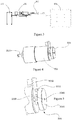
- FIG 3 shows a structural view illustrating the process of controlling the antenna phase shifter by the electrically adjustable antenna control system as shown in figures 1-2 .
- the antenna phase shifter 404 moves along with a drawbar 402 under the drive of the DC geared motor 202, thus changing the phase angle of the antenna elements.
- the control board 102 sends commands to the DC geared motor 202 such that the motor 202 is driven to rotate, thus resulting move of the drawbar 402.
- a stop block (not labeled) is provided on the drawbar 402 and moves between the two travel switches 3022 disposed on the travel plate 302 (see figure 2 ). When the stop block touches contacting point of a travel switch 3022, the motor 202 begin to rotate in a reverse direction and the counter device 304 starts counting.
- the control board 102 calculates required revolutions of the motor to move to a corresponding location, hence changing the phase of the phase shifter 404 and further changing antenna pattern.
- the counter device 304 may be a sensor such as a HALL sensor, photoelectric sensor and the like.
- the counter device 304 includes a sensor circuit board 3042 secured on the rear end of the motor 202, a HALL sensor 3044 disposed on the sensor circuit board 3042, a rotary disc 3046 connected with a motor shaft 2024 of the motor 202 so as to rotate together with the shaft 2024, and a pair of permanent magnets 3048 located on the rotary disc 3046.
- the motor 202 operates, the rotary disc 3046 will be driven to rotate.
- the HALL sensor 3044 will generate pulse when the permanent magnet 3048 passes through its upper end.
- the rotary location of the motor 202 may be calculated by recording pulse numbers.
- the displacement required by a slider of the phase shifter 404 may be determined according to specific electrical characteristics requirement.
- the control board 102 After receiving the corresponding commands, the control board 102 will calculate the steps to rotate by the motor 202 (each pulse received by the control board 102 from the HALL sensor is defined as 1 step). Then, the operation of the motor 202 is controlled under the following principles.
- the electrically adjustable antenna control system 100 of the invention is intended to transform rotary movement of the motor 202 into linear movement and cause the slider of phase shifter 404 of the electrically adjustable antenna to be moved within a certain path (herein, the two endpoints of the path are defined as a starting point and an ending point). Furthermore, the slider can stay on certain location within the path according to requirement. Moreover, locating tolerance meets certain need. In present system 100, the distance of the path is that between the contacting points of the two travel switches 3022 of the travel plate 302.
- the distance between the phase shifter and starting point is defined as an actual distance.
- the distance between the phase shifter at a target location in the path and the starting point is defined as a target distance.
- the deviation between the actual distance defined between an actual location of the phase shifter and starting point and the target distance is defined as locating tolerance.
- target range The sum of the target distance and locating tolerance under the condition of meeting requirement (permitted by the system) is defined as target range.
- the rotation direction along which the motor rotates to move the phase shifter from the starting point to the ending point is defined as forward direction.
- the rotation direction along which the motor rotates to move the phase shifter from the ending point to the starting point is defined as reverse direction.
- the period of motor control is 2ms, and in each control period, the speed change of the motor will be calculated according to the actual distance, speed and target distance, thus obtaining the operation status of the motor in a next operation period.
- the operation of the motor is controlled such that the phase shifter will gradually move to the target distance.
- the motor will be stopped when the actual distance of the phase shifter is within the above target range.
- the flow chart of the motor control is denoted in figure 6 .
- the actual distance of the phase shifter is 0 (in other words, the phase shifter is at the starting point)
- the target distance is 1000 steps
- the target range is set to be within 1000 ⁇ 10 steps moved by the phase shifter.
- the operation direction of the motor is set to be forward direction based on the entire process and the speed of the motor is also set. After that, the motor starts. The motor will enter into next period 2ms later, and the above process is repeated until the motor arrives at the target range, thus finishing the command of this time.
- a trapezoidal speed control method is employed in present invention to reduce locating tolerance caused by inherent inertia of the control system 100 such that the locating precision meets system requirement.
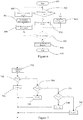
- the present invention also proposes an electrically adjustable antenna control method performed by the above control system 100. As shown in figures 1-2 and 6 , at first the process is started (step 601). Then, the control board 102 determines whether the actual distance of the phase shifter 404 is larger than the target distance (step 602).
- control board 102 sets reverse operation flag of the motor 202 (step 603); otherwise, the control board 102 sets forward operation flag of the motor 202 (step 604).
- step 605 it is determined whether the actual distance of the phase shifter 404 is located within the target range (step 605) and if yes, then corresponding flag is set and the motor is stopped (step 609)and the entire process is ended (step 610). If no, the control board 102 continues to calculate and set the operation speed of the motor (step 606) and set operation direction of the motor (step 607), and then drive the motor to operate (step 608).
- steps 602-605 are repeated until it is determined that the actual distance of the phase shifter 404 is already within the target range in step 605, and next, corresponding flag is set and the motor is stopped (step 609), and the entire process is ended (step 610).
- the trapezoidal speed control method of the present invention controls the operation speed in step 606.
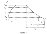
- some terms should be defined. Assume that during operation the motor has some different speeds V min , V 1 , V 2 and V max , wherein V min ⁇ V 1 ⁇ V 2 ⁇ V maz , V min is minimum speed, and V max is maximum speed.
- the different between the actual distance and target distance of the phase shifter 404 is defined as the rest distance S.
- the rest distance S has three threshold values, that is, a first threshold value S 3 , a second threshold value S 2 and a third threshold value S 1 , wherein 0 ⁇ S 1 ⁇ S 2 ⁇ S 3 .
- the rest distance S of the phase shifter 404 is calculated (by the control board 102) (step 701). Then, it is determined whether the rest distance S of the phase shifter 404 is larger than the first threshold value S 3 (step 702). If yes, then the motor is set to have a maximum speed V max (step 703). Otherwise, it is judged whether the rest distance S of the phase shifter 404 is larger than the second threshold value S 2 (step 704). If yes, the motor is set to have a speed V 2 (step 705). Otherwise, it is further judged whether the rest distance S of the phase shifter 404 is larger than the third threshold value S 1 (step 706). If yes, the motor is set to have a speed V 1 (step 708). Otherwise, the motor is set to have a speed V min (step 707).
- N represents the total number of the controllable speeds ranging from V min to V max .
- the smoothness of the trapezoidal speed control is relevant to the number N. If N is larger, then the trapezoidal speed control will have better smoothness. On the contrary, the trapezoidal speed control will have worse smoothness.
- N tends to be infinite, in other word, the system speed between V min and V max can be adjusted continuously
- the speed curve of the motor operation is shown in figure 8 .
- the motor When the rest distance S > S 3 , the motor will operate with increased speed and after time t 0 , the motor will operate at the maximum speed V max . The motor speed will be reduced to V 2 when it is close to the first threshold value S 3 . Afterwards, the motor will operate at V 2 . When the motor is close to the second threshold value S 2 , its speed will be decreased to V 1 .
Landscapes
- Engineering & Computer Science (AREA)
- Power Engineering (AREA)
- Variable-Direction Aerials And Aerial Arrays (AREA)
- Output Control And Ontrol Of Special Type Engine (AREA)
- Computer Networks & Wireless Communication (AREA)
Claims (4)
- Ein System zur Steuerung einer elektrisch einstellbaren Antenne, aufweisend eine Steuerung (10), einen Betätigungsmechanismus (20), der konfiguriert ist, um von der Steuerung (10) gesteuert zu werden, und eine Rückkopplungsschleife (30), die mit sowohl der Steuerung (10) als auch dem Betätigungsmechanismus (20) verbunden ist,
wobei die Steuerung (10) eine Steuertafel (102) und deren eingebettetes Programm aufweist; wobei der Betätigungsmechanismus (20) einen DC-Getriebemotor (202), der konfiguriert ist, um von der Steuertafel (102) und dem eingebetteten Programm gesteuert zu werden, und einen elektrisch einstellbaren Antennenphasenschieber, der konfiguriert ist, um vom DC-Getriebemotor (202) angetrieben zu werden, aufweist; wobei:die Rückkopplungsschleife (30) eine Fahrplatte (302), die mit sowohl der Steuertafel (102) als auch dem DC-Getriebemotor (202) elektrisch gekoppelt ist, und eine Zählvorrichtung (304), die auf einem hinteren Ende des DC-Getriebemotors (202) installiert ist, aufweist;der DC-Getriebemotor (202) über eine Zugstange (402), die einen Anschlagblock aufweist, mit dem Antennenphasenschieber verbunden ist; wobei die Rückkopplungsschleife (30) ferner zwei Fahrschalter (3022) auf der Fahrplatte (302) aufweist und jeder Fahrschalter (3022) mit einem Kontaktpunkt bereitgestellt wird;die Steuertafel (102) konfiguriert ist, um dem DC-Getriebemotor (202) Befehle zu senden, um den Motor (202) anzutreiben, so dass er sich dreht und seinerseits die Bewegung der Zugstange (402) bewirkt; wobei der Anschlagblock konfiguriert ist, um sich zwischen den zwei Fahrschaltern (3022) der Fahrplatte (302) zu bewegen; wobei der Motor (202) konfiguriert ist, um damit zu beginnen, sich in einer Rückwärtsrichtung zu drehen, und die Zählvorrichtung (304) konfiguriert ist, um damit zu beginnen, zu zählen, wenn der Anschlagblock den Kontaktpunkt eines Fahrschalters (3022) berührt; und wobei die Zählvorrichtung (304) zudem konfiguriert ist, um damit aufzuhören, zu zählen, wenn der Anschlagblock den Kontaktpunkt des anderen Fahrschalters (3022) berührt, und den Gesamtzählwert zur Steuertafel (102) zurückzusenden, wobei die Steuertafel (102) konfiguriert ist, um die erforderlichen Umdrehungen des Motors (202), um sich zu einer entsprechenden Position zu bewegen, mittels des Werts der Zählvorrichtung (304) zu berechnen. - Das System zur Steuerung einer elektrisch einstellbaren Antenne nach Anspruch 1, wobei die Zählvorrichtung (304) eine Sensorplatine (3042), die auf dem hinteren Ende des Motors (202) befestigt ist, einen HALL-Sensor (3044), der auf der Sensorplatine (3042) angeordnet ist, eine Drehscheibe (3046), die mit einer Motorwelle (2024) des Motors (202) verbunden ist, um sich zusammen mit der Welle (2024) zu drehen, und Permanentmagneten (3048), die auf der Drehscheibe (3046) angeordnet sind, aufweist.
- Ein Verfahren zur Steuerung einer elektrisch einstellbaren Antenne für das System nach Anspruch 1,
wobei zwei Endpunkte eines Wegs zwischen zwei Kontaktpunkten von zwei Fahrschaltern (3022) der Fahrplatte (302) jeweils als Startpunkt und Endpunkt definiert werden; wobei der Abstand zwischen dem Phasenschieber und dem Startpunkt als tatsächlicher Abstand definiert wird; wobei der Abstand zwischen dem Phasenschieber und einer Zielposition auf dem Weg und dem Startpunkt als Zielabstand definiert wird; wobei die Abweichung zwischen einem Abstand, der zwischen einer tatsächlichen Position des Phasenschiebers und dem Startpunkt definiert wird, und dem Zielabstand als Positionstoleranz definiert wird; wobei die Summe des Zielabstands und der Positionstoleranz als Zielbereich definiert wird; wobei das Verfahren die folgenden Schritte aufweist:Schritt 601: Start des Prozesses;Schritt 602: die Steuertafel (102) bestimmt, ob der tatsächliche Abstand des Phasenschiebers größer ist als der Zielabstand;Schritt 603: falls der tatsächliche Abstand größer ist als der Zielabstand des Phasenschiebers, stellt die Steuertafel (102) die Rückwärtsbetrieb-Markierung des Motors (202) ein; andernfalls:Schritt (604): die Steuertafel (102) stellt die Vorwärtsbetrieb-Markierung des Motors (202) ein;Schritt 605: Bestimmen, ob sich der tatsächliche Abstand des Phasenschiebers innerhalb des Zielbereichs befindet, und, falls ja, dann nacheinander Durchführen der nachfolgend aufgeführten folgenden Schritte 609 und 610; und, wenn nein, dann Durchführen der Schritte 606-608 und dann Fortsetzen der Durchführung der Schritte 602-605, bis bestimmt ist, dass der tatsächliche Abstand des Phasenschiebers bereits innerhalb des Zielbereichs in Schritt 605 ist, und anschließend Durchführen der Schritte 609 und 610;Schritt 606: die Steuertafel (102) fährt damit fort, die Betriebsgeschwindigkeit des Motors (202) zu berechnen und einzustellen;Schritt 607: Einstellen der Betriebsrichtung des Motors (202);Schritt 608: Antreiben des Motors (202), so dass er in Betrieb ist;Schritt 609: Einstellen entsprechender Markierungen und Anhalten des Motors (202); undSchritt 610: Beenden des gesamten Prozesses. - Das Verfahren zur Steuerung einer elektrisch einstellbaren Antenne nach Anspruch 3, wobei:
vorausgesetzt wird, dass der Motor (202) während des Betriebs einige unterschiedliche Geschwindigkeiten Vmin, V1, V2 und Vmax aufweist, wobei Vmin < V1 < V2 < Vmax, wobei Vmin die Mindestgeschwindigkeit ist und Vmax die Höchstgeschwindigkeit ist; wobei die Differenz zwischen dem tatsächlichen Abstand und dem Zielabstand des Phasenschiebers als Restabstand S definiert wird; und wobei zudem vorausgesetzt wird, dass der Restabstand S drei Schwellenwerte, das heißt, einen ersten Schwellenwert S3, einen zweiten Schwellenwert S2 und einen dritten Schwellenwert S1 aufweist, wobei 0 < S1 < S2 <S3, wobei der Schritt, in dem die Steuertafel (102) fortfährt, die Betriebsgeschwindigkeit des Motors (202) zu berechnen und einzustellen, die folgenden Schritte aufweist:Schritt 701: der Restabstand S des Phasenschiebers wird von der Steuertafel (102) berechnet;Schritt 702: es wird bestimmt, ob der Restabstand S des Phasenschiebers größer ist als der erste Schwellenwert S3, falls ja, Durchführen von Schritt 703, andernfalls Durchführen von Schritt 704;Schritt 703: der Motor (202) wird eingestellt, um eine Höchstgeschwindigkeit aufzuweisen;Schritt 704: es wird beurteilt, ob der Restabstand S des Phasenschiebers größer ist als der zweite Schwellenwert S2, falls ja, Durchführen von Schritt 705, andernfalls Durchführen von Schritt 706;Schritt 705: der Motor (202) wird eingestellt, um eine Geschwindigkeit aufzuweisen;Schritt 706: es wird ferner beurteilt, ob der Restabstand S des Phasenschiebers größer ist als der dritte Schwellenwert S1; falls ja, Durchführen von Schritt 708, andernfalls Durchführen von Schritt 707;Schritt 707: der Motor (202) wird eingestellt, um eine Geschwindigkeit Vmin aufzuweisen;Schritt 708: der Motor (202) wird eingestellt, um eine Geschwindigkeit V1 aufzuweisen.
Applications Claiming Priority (2)
| Application Number | Priority Date | Filing Date | Title |
|---|---|---|---|
| CN201010529379.7A CN102055069B (zh) | 2010-11-01 | 2010-11-01 | 电调天线控制系统及方法 |
| PCT/CN2011/081481 WO2012059026A1 (zh) | 2010-11-01 | 2011-10-28 | 电调天线控制系统及方法 |
Publications (3)
| Publication Number | Publication Date |
|---|---|
| EP2637252A1 EP2637252A1 (de) | 2013-09-11 |
| EP2637252A4 EP2637252A4 (de) | 2016-04-13 |
| EP2637252B1 true EP2637252B1 (de) | 2019-03-06 |
Family
ID=43959171
Family Applications (1)
| Application Number | Title | Priority Date | Filing Date |
|---|---|---|---|
| EP11837552.6A Active EP2637252B1 (de) | 2010-11-01 | 2011-10-28 | System und verfahren zur steuerung einer elektrischen kippantenne |
Country Status (7)
| Country | Link |
|---|---|
| US (1) | US9065381B2 (de) |
| EP (1) | EP2637252B1 (de) |
| CN (1) | CN102055069B (de) |
| BR (1) | BR112013010637A2 (de) |
| ES (1) | ES2729059T3 (de) |
| TR (1) | TR201907778T4 (de) |
| WO (1) | WO2012059026A1 (de) |
Families Citing this family (12)
| Publication number | Priority date | Publication date | Assignee | Title |
|---|---|---|---|---|
| CN102055069B (zh) * | 2010-11-01 | 2014-10-29 | 京信通信系统(中国)有限公司 | 电调天线控制系统及方法 |
| CN104090531B (zh) * | 2014-06-06 | 2017-01-04 | 西安华为技术有限公司 | 开关组件、开关组件控制方法、控制器及基站 |
| US10476152B2 (en) | 2017-12-15 | 2019-11-12 | United States Of America As Represented By Secretary Of The Navy | System and method for automatic real time control of the rotational speed of a radar antenna |
| CN108736125B (zh) * | 2018-04-23 | 2022-03-11 | 江苏科技大学 | 一种移动通信车天线自动校对方法 |
| CN108923128B (zh) * | 2018-06-29 | 2021-01-22 | 京信通信技术(广州)有限公司 | 一种基站天线的电调方法及设备 |
| CN109449598B (zh) * | 2018-10-26 | 2021-01-22 | 京信通信技术(广州)有限公司 | 一种电调天线的倾角调整方法及对应装置 |
| CN110676584B (zh) * | 2019-09-12 | 2021-03-23 | 广东盛路通信科技股份有限公司 | 一种精准调天线倾角的控制方法 |
| CN110690572B (zh) * | 2019-09-12 | 2020-11-24 | 广东盛路通信科技股份有限公司 | 一种基于stm32f0微控制器的天线倾角调节控制方法 |
| CN111180891B (zh) * | 2020-01-06 | 2021-12-14 | 武汉虹信科技发展有限责任公司 | 多频电调天线的调节方法 |
| CN111267682B (zh) * | 2020-03-25 | 2020-11-03 | 北京经纬恒润科技有限公司 | 座椅位置监测方法、装置及控制器 |
| US11942682B2 (en) | 2021-04-21 | 2024-03-26 | Skyworks Solutions, Inc. | Electrically adjustable stencil for controlling antenna pattern for beamforming |
| CN113534716B (zh) * | 2021-07-21 | 2023-07-04 | 山西大同大学 | 一种几何相位连续可调谐的机械式超表面控制系统及方法 |
Family Cites Families (18)
| Publication number | Priority date | Publication date | Assignee | Title |
|---|---|---|---|---|
| US3932796A (en) * | 1972-02-09 | 1976-01-13 | Textron, Inc. | Control system for producing multi-axis contour movement for a stepping motor drive |
| US3793634A (en) * | 1972-07-31 | 1974-02-19 | Westinghouse Electric Corp | Digital antenna positioning system and method |
| WO1996014670A1 (en) * | 1994-11-04 | 1996-05-17 | Deltec New Zealand Limited | An antenna control system |
| US6195060B1 (en) * | 1999-03-09 | 2001-02-27 | Harris Corporation | Antenna positioner control system |
| DE10104564C1 (de) * | 2001-02-01 | 2002-09-19 | Kathrein Werke Kg | Steuerungsvorrichtung zum Einstellen eines unterschiedlichen Absenkwinkels insbesondere von zu einer Basisstation gehörenden Mobilfunkantennen sowie eine zugehörige Antenne und Verfahren zur Veränderung eines Absenkwinkels |
| FR2851694B1 (fr) * | 2003-02-24 | 2005-05-20 | Jaybeam Ltd | Antenne a commande electrique du depointage |
| US20050280594A1 (en) * | 2004-06-02 | 2005-12-22 | Robert Dennison | Antenna rotor system |
| CN1332175C (zh) * | 2005-08-23 | 2007-08-15 | 广州杰赛科技股份有限公司 | 通信天线电下倾角度的检测装置及检测方法 |
| CN2872622Y (zh) * | 2006-03-23 | 2007-02-21 | 京信通信技术(广州)有限公司 | 调整移动通信天线电下倾角的控制装置 |
| CN100565409C (zh) * | 2007-05-21 | 2009-12-02 | 上海宝信软件股份有限公司 | 二方向二速定位控制方法 |
| EP2232633A4 (de) * | 2007-11-26 | 2014-03-12 | Powerwave Technologies Inc | Antenne mit einzelansteuerungsvariablem azimut und strahlneigung für ein drahtloses netzwerk |
| CN101521312B (zh) * | 2008-02-29 | 2013-05-22 | 京信通信系统(中国)有限公司 | 天线移相系统 |
| CN101518881A (zh) * | 2009-03-26 | 2009-09-02 | 王建滨 | 一种磁分度装置 |
| CN101621156B (zh) * | 2009-08-05 | 2012-11-07 | 宁波天韵天线科技有限公司 | 一种电调天线控制装置 |
| US8436779B2 (en) * | 2010-03-19 | 2013-05-07 | Bruce Kenneth Clifford | Apparatus for aligning an antenna in a reference position |
| TWI431846B (zh) * | 2010-10-01 | 2014-03-21 | Wistron Neweb Corp | 對位調整裝置及衛星天線 |
| CN201838719U (zh) * | 2010-11-01 | 2011-05-18 | 京信通信系统(中国)有限公司 | 电调天线控制系统 |
| CN102055069B (zh) * | 2010-11-01 | 2014-10-29 | 京信通信系统(中国)有限公司 | 电调天线控制系统及方法 |
-
2010
- 2010-11-01 CN CN201010529379.7A patent/CN102055069B/zh active Active
-
2011
- 2011-10-28 US US13/882,506 patent/US9065381B2/en active Active
- 2011-10-28 ES ES11837552T patent/ES2729059T3/es active Active
- 2011-10-28 BR BR112013010637A patent/BR112013010637A2/pt active Search and Examination
- 2011-10-28 WO PCT/CN2011/081481 patent/WO2012059026A1/zh active Application Filing
- 2011-10-28 TR TR2019/07778T patent/TR201907778T4/tr unknown
- 2011-10-28 EP EP11837552.6A patent/EP2637252B1/de active Active
Non-Patent Citations (1)
| Title |
|---|
| None * |
Also Published As
| Publication number | Publication date |
|---|---|
| EP2637252A4 (de) | 2016-04-13 |
| US20140197763A1 (en) | 2014-07-17 |
| TR201907778T4 (tr) | 2019-06-21 |
| EP2637252A1 (de) | 2013-09-11 |
| ES2729059T3 (es) | 2019-10-30 |
| BR112013010637A2 (pt) | 2016-08-09 |
| CN102055069B (zh) | 2014-10-29 |
| WO2012059026A1 (zh) | 2012-05-10 |
| US9065381B2 (en) | 2015-06-23 |
| CN102055069A (zh) | 2011-05-11 |
Similar Documents
| Publication | Publication Date | Title |
|---|---|---|
| EP2637252B1 (de) | System und verfahren zur steuerung einer elektrischen kippantenne | |
| CN201075175Y (zh) | 一种加工中心刀库 | |
| CN109449598B (zh) | 一种电调天线的倾角调整方法及对应装置 | |
| CN101689824B (zh) | 通过驱动分段的行程来校准步进电动机 | |
| JP2014101919A (ja) | レンジ切換装置 | |
| CN109257000A (zh) | 一种开关磁阻电机宽转速范围混合调速控制方法 | |
| JPH062650A (ja) | 計量ポンプ装置 | |
| CN114553070A (zh) | 电机启动控制方法 | |
| CN201838719U (zh) | 电调天线控制系统 | |
| RU2009105173A (ru) | Способ и устройство для управления положением цифровых дисков нумерационного устройства | |
| CN113258840A (zh) | 一种步进电机控制系统及方法 | |
| CN201541226U (zh) | 可实现选位的马达控制装置 | |
| US20100085003A1 (en) | Apparatus and method for controlling an actuator | |
| CN102476550B (zh) | 刻印控制方法 | |
| CN105827165B (zh) | 反应式步进电机的驱动方法、驱动系统及其驱动器 | |
| CN110932621B (zh) | 一种步进电机零点检测方法及装置 | |
| CN115765541A (zh) | 一种无线激光通信平台的电机控制系统及控制方法 | |
| US20040119428A1 (en) | Positioning apparatus using brushless motor | |
| JP2013172527A (ja) | 移動体追尾駆動装置 | |
| JP2002325474A (ja) | モータ制御装置 | |
| CN103592954B (zh) | 基于霍尔传感器定位的活动机构控制方法 | |
| CN2795916Y (zh) | 光电编码电机控制装置 | |
| CN111650805B (zh) | 一种基于旋转电磁铁切换机构的双视场快速切换装置及方法 | |
| US9825566B2 (en) | Motor control apparatus | |
| CN117938018A (zh) | 一种调姿平台的电机姿态控制方法、装置及设备 |
Legal Events
| Date | Code | Title | Description |
|---|---|---|---|
| PUAI | Public reference made under article 153(3) epc to a published international application that has entered the european phase |
Free format text: ORIGINAL CODE: 0009012 |
|
| 17P | Request for examination filed |
Effective date: 20130530 |
|
| AK | Designated contracting states |
Kind code of ref document: A1 Designated state(s): AL AT BE BG CH CY CZ DE DK EE ES FI FR GB GR HR HU IE IS IT LI LT LU LV MC MK MT NL NO PL PT RO RS SE SI SK SM TR |
|
| DAX | Request for extension of the european patent (deleted) | ||
| RA4 | Supplementary search report drawn up and despatched (corrected) |
Effective date: 20160310 |
|
| RIC1 | Information provided on ipc code assigned before grant |
Ipc: H02P 31/00 20060101ALI20160304BHEP Ipc: H01Q 3/32 20060101AFI20160304BHEP Ipc: H01Q 1/24 20060101ALN20160304BHEP Ipc: G05D 3/20 20060101ALI20160304BHEP Ipc: G05B 19/40 20060101ALI20160304BHEP |
|
| GRAP | Despatch of communication of intention to grant a patent |
Free format text: ORIGINAL CODE: EPIDOSNIGR1 |
|
| STAA | Information on the status of an ep patent application or granted ep patent |
Free format text: STATUS: GRANT OF PATENT IS INTENDED |
|
| RIC1 | Information provided on ipc code assigned before grant |
Ipc: H02P 31/00 20060101ALI20181003BHEP Ipc: H01Q 3/32 20060101AFI20181003BHEP Ipc: H01Q 1/24 20060101ALN20181003BHEP |
|
| INTG | Intention to grant announced |
Effective date: 20181022 |
|
| GRAS | Grant fee paid |
Free format text: ORIGINAL CODE: EPIDOSNIGR3 |
|
| GRAA | (expected) grant |
Free format text: ORIGINAL CODE: 0009210 |
|
| STAA | Information on the status of an ep patent application or granted ep patent |
Free format text: STATUS: THE PATENT HAS BEEN GRANTED |
|
| AK | Designated contracting states |
Kind code of ref document: B1 Designated state(s): AL AT BE BG CH CY CZ DE DK EE ES FI FR GB GR HR HU IE IS IT LI LT LU LV MC MK MT NL NO PL PT RO RS SE SI SK SM TR |
|
| REG | Reference to a national code |
Ref country code: GB Ref legal event code: FG4D |
|
| REG | Reference to a national code |
Ref country code: CH Ref legal event code: EP Ref country code: AT Ref legal event code: REF Ref document number: 1105797 Country of ref document: AT Kind code of ref document: T Effective date: 20190315 |
|
| REG | Reference to a national code |
Ref country code: DE Ref legal event code: R096 Ref document number: 602011056970 Country of ref document: DE |
|
| REG | Reference to a national code |
Ref country code: IE Ref legal event code: FG4D |
|
| REG | Reference to a national code |
Ref country code: NL Ref legal event code: MP Effective date: 20190306 |
|
| REG | Reference to a national code |
Ref country code: LT Ref legal event code: MG4D |
|
| PG25 | Lapsed in a contracting state [announced via postgrant information from national office to epo] |
Ref country code: NO Free format text: LAPSE BECAUSE OF FAILURE TO SUBMIT A TRANSLATION OF THE DESCRIPTION OR TO PAY THE FEE WITHIN THE PRESCRIBED TIME-LIMIT Effective date: 20190606 Ref country code: LT Free format text: LAPSE BECAUSE OF FAILURE TO SUBMIT A TRANSLATION OF THE DESCRIPTION OR TO PAY THE FEE WITHIN THE PRESCRIBED TIME-LIMIT Effective date: 20190306 Ref country code: SE Free format text: LAPSE BECAUSE OF FAILURE TO SUBMIT A TRANSLATION OF THE DESCRIPTION OR TO PAY THE FEE WITHIN THE PRESCRIBED TIME-LIMIT Effective date: 20190306 Ref country code: FI Free format text: LAPSE BECAUSE OF FAILURE TO SUBMIT A TRANSLATION OF THE DESCRIPTION OR TO PAY THE FEE WITHIN THE PRESCRIBED TIME-LIMIT Effective date: 20190306 |
|
| PG25 | Lapsed in a contracting state [announced via postgrant information from national office to epo] |
Ref country code: LV Free format text: LAPSE BECAUSE OF FAILURE TO SUBMIT A TRANSLATION OF THE DESCRIPTION OR TO PAY THE FEE WITHIN THE PRESCRIBED TIME-LIMIT Effective date: 20190306 Ref country code: RS Free format text: LAPSE BECAUSE OF FAILURE TO SUBMIT A TRANSLATION OF THE DESCRIPTION OR TO PAY THE FEE WITHIN THE PRESCRIBED TIME-LIMIT Effective date: 20190306 Ref country code: BG Free format text: LAPSE BECAUSE OF FAILURE TO SUBMIT A TRANSLATION OF THE DESCRIPTION OR TO PAY THE FEE WITHIN THE PRESCRIBED TIME-LIMIT Effective date: 20190606 Ref country code: GR Free format text: LAPSE BECAUSE OF FAILURE TO SUBMIT A TRANSLATION OF THE DESCRIPTION OR TO PAY THE FEE WITHIN THE PRESCRIBED TIME-LIMIT Effective date: 20190607 Ref country code: HR Free format text: LAPSE BECAUSE OF FAILURE TO SUBMIT A TRANSLATION OF THE DESCRIPTION OR TO PAY THE FEE WITHIN THE PRESCRIBED TIME-LIMIT Effective date: 20190306 Ref country code: NL Free format text: LAPSE BECAUSE OF FAILURE TO SUBMIT A TRANSLATION OF THE DESCRIPTION OR TO PAY THE FEE WITHIN THE PRESCRIBED TIME-LIMIT Effective date: 20190306 |
|
| REG | Reference to a national code |
Ref country code: AT Ref legal event code: MK05 Ref document number: 1105797 Country of ref document: AT Kind code of ref document: T Effective date: 20190306 |
|
| REG | Reference to a national code |
Ref country code: ES Ref legal event code: FG2A Ref document number: 2729059 Country of ref document: ES Kind code of ref document: T3 Effective date: 20191030 |
|
| PG25 | Lapsed in a contracting state [announced via postgrant information from national office to epo] |
Ref country code: PT Free format text: LAPSE BECAUSE OF FAILURE TO SUBMIT A TRANSLATION OF THE DESCRIPTION OR TO PAY THE FEE WITHIN THE PRESCRIBED TIME-LIMIT Effective date: 20190706 Ref country code: AL Free format text: LAPSE BECAUSE OF FAILURE TO SUBMIT A TRANSLATION OF THE DESCRIPTION OR TO PAY THE FEE WITHIN THE PRESCRIBED TIME-LIMIT Effective date: 20190306 Ref country code: SK Free format text: LAPSE BECAUSE OF FAILURE TO SUBMIT A TRANSLATION OF THE DESCRIPTION OR TO PAY THE FEE WITHIN THE PRESCRIBED TIME-LIMIT Effective date: 20190306 Ref country code: RO Free format text: LAPSE BECAUSE OF FAILURE TO SUBMIT A TRANSLATION OF THE DESCRIPTION OR TO PAY THE FEE WITHIN THE PRESCRIBED TIME-LIMIT Effective date: 20190306 Ref country code: IT Free format text: LAPSE BECAUSE OF FAILURE TO SUBMIT A TRANSLATION OF THE DESCRIPTION OR TO PAY THE FEE WITHIN THE PRESCRIBED TIME-LIMIT Effective date: 20190306 Ref country code: CZ Free format text: LAPSE BECAUSE OF FAILURE TO SUBMIT A TRANSLATION OF THE DESCRIPTION OR TO PAY THE FEE WITHIN THE PRESCRIBED TIME-LIMIT Effective date: 20190306 Ref country code: EE Free format text: LAPSE BECAUSE OF FAILURE TO SUBMIT A TRANSLATION OF THE DESCRIPTION OR TO PAY THE FEE WITHIN THE PRESCRIBED TIME-LIMIT Effective date: 20190306 |
|
| PG25 | Lapsed in a contracting state [announced via postgrant information from national office to epo] |
Ref country code: SM Free format text: LAPSE BECAUSE OF FAILURE TO SUBMIT A TRANSLATION OF THE DESCRIPTION OR TO PAY THE FEE WITHIN THE PRESCRIBED TIME-LIMIT Effective date: 20190306 Ref country code: PL Free format text: LAPSE BECAUSE OF FAILURE TO SUBMIT A TRANSLATION OF THE DESCRIPTION OR TO PAY THE FEE WITHIN THE PRESCRIBED TIME-LIMIT Effective date: 20190306 |
|
| REG | Reference to a national code |
Ref country code: DE Ref legal event code: R097 Ref document number: 602011056970 Country of ref document: DE |
|
| PG25 | Lapsed in a contracting state [announced via postgrant information from national office to epo] |
Ref country code: IS Free format text: LAPSE BECAUSE OF FAILURE TO SUBMIT A TRANSLATION OF THE DESCRIPTION OR TO PAY THE FEE WITHIN THE PRESCRIBED TIME-LIMIT Effective date: 20190706 Ref country code: AT Free format text: LAPSE BECAUSE OF FAILURE TO SUBMIT A TRANSLATION OF THE DESCRIPTION OR TO PAY THE FEE WITHIN THE PRESCRIBED TIME-LIMIT Effective date: 20190306 |
|
| PLBE | No opposition filed within time limit |
Free format text: ORIGINAL CODE: 0009261 |
|
| STAA | Information on the status of an ep patent application or granted ep patent |
Free format text: STATUS: NO OPPOSITION FILED WITHIN TIME LIMIT |
|
| PG25 | Lapsed in a contracting state [announced via postgrant information from national office to epo] |
Ref country code: DK Free format text: LAPSE BECAUSE OF FAILURE TO SUBMIT A TRANSLATION OF THE DESCRIPTION OR TO PAY THE FEE WITHIN THE PRESCRIBED TIME-LIMIT Effective date: 20190306 |
|
| 26N | No opposition filed |
Effective date: 20191209 |
|
| PG25 | Lapsed in a contracting state [announced via postgrant information from national office to epo] |
Ref country code: SI Free format text: LAPSE BECAUSE OF FAILURE TO SUBMIT A TRANSLATION OF THE DESCRIPTION OR TO PAY THE FEE WITHIN THE PRESCRIBED TIME-LIMIT Effective date: 20190306 |
|
| REG | Reference to a national code |
Ref country code: DE Ref legal event code: R119 Ref document number: 602011056970 Country of ref document: DE |
|
| PG25 | Lapsed in a contracting state [announced via postgrant information from national office to epo] |
Ref country code: MC Free format text: LAPSE BECAUSE OF FAILURE TO SUBMIT A TRANSLATION OF THE DESCRIPTION OR TO PAY THE FEE WITHIN THE PRESCRIBED TIME-LIMIT Effective date: 20190306 |
|
| REG | Reference to a national code |
Ref country code: CH Ref legal event code: PL |
|
| PG25 | Lapsed in a contracting state [announced via postgrant information from national office to epo] |
Ref country code: LI Free format text: LAPSE BECAUSE OF NON-PAYMENT OF DUE FEES Effective date: 20191031 Ref country code: LU Free format text: LAPSE BECAUSE OF NON-PAYMENT OF DUE FEES Effective date: 20191028 Ref country code: DE Free format text: LAPSE BECAUSE OF NON-PAYMENT OF DUE FEES Effective date: 20200501 Ref country code: CH Free format text: LAPSE BECAUSE OF NON-PAYMENT OF DUE FEES Effective date: 20191031 |
|
| REG | Reference to a national code |
Ref country code: BE Ref legal event code: MM Effective date: 20191031 |
|
| PG25 | Lapsed in a contracting state [announced via postgrant information from national office to epo] |
Ref country code: BE Free format text: LAPSE BECAUSE OF NON-PAYMENT OF DUE FEES Effective date: 20191031 |
|
| PG25 | Lapsed in a contracting state [announced via postgrant information from national office to epo] |
Ref country code: FR Free format text: LAPSE BECAUSE OF NON-PAYMENT OF DUE FEES Effective date: 20191031 Ref country code: IE Free format text: LAPSE BECAUSE OF NON-PAYMENT OF DUE FEES Effective date: 20191028 |
|
| REG | Reference to a national code |
Ref country code: GB Ref legal event code: 732E Free format text: REGISTERED BETWEEN 20210128 AND 20210203 |
|
| REG | Reference to a national code |
Ref country code: ES Ref legal event code: PC2A Owner name: COMBA TELECOM TECHNOLOGY (GUANGZHOU) LIMITED Effective date: 20210303 |
|
| PG25 | Lapsed in a contracting state [announced via postgrant information from national office to epo] |
Ref country code: CY Free format text: LAPSE BECAUSE OF FAILURE TO SUBMIT A TRANSLATION OF THE DESCRIPTION OR TO PAY THE FEE WITHIN THE PRESCRIBED TIME-LIMIT Effective date: 20190306 |
|
| PG25 | Lapsed in a contracting state [announced via postgrant information from national office to epo] |
Ref country code: HU Free format text: LAPSE BECAUSE OF FAILURE TO SUBMIT A TRANSLATION OF THE DESCRIPTION OR TO PAY THE FEE WITHIN THE PRESCRIBED TIME-LIMIT; INVALID AB INITIO Effective date: 20111028 Ref country code: MT Free format text: LAPSE BECAUSE OF FAILURE TO SUBMIT A TRANSLATION OF THE DESCRIPTION OR TO PAY THE FEE WITHIN THE PRESCRIBED TIME-LIMIT Effective date: 20190306 |
|
| PG25 | Lapsed in a contracting state [announced via postgrant information from national office to epo] |
Ref country code: MK Free format text: LAPSE BECAUSE OF FAILURE TO SUBMIT A TRANSLATION OF THE DESCRIPTION OR TO PAY THE FEE WITHIN THE PRESCRIBED TIME-LIMIT Effective date: 20190306 |
|
| P01 | Opt-out of the competence of the unified patent court (upc) registered |
Effective date: 20230517 |
|
| PGFP | Annual fee paid to national office [announced via postgrant information from national office to epo] |
Ref country code: GB Payment date: 20231020 Year of fee payment: 13 |
|
| PGFP | Annual fee paid to national office [announced via postgrant information from national office to epo] |
Ref country code: ES Payment date: 20231227 Year of fee payment: 13 |
|
| PGFP | Annual fee paid to national office [announced via postgrant information from national office to epo] |
Ref country code: TR Payment date: 20231026 Year of fee payment: 13 |