EP2637038A1 - Appareil de mesure de distance - Google Patents
Appareil de mesure de distance Download PDFInfo
- Publication number
- EP2637038A1 EP2637038A1 EP12158382.7A EP12158382A EP2637038A1 EP 2637038 A1 EP2637038 A1 EP 2637038A1 EP 12158382 A EP12158382 A EP 12158382A EP 2637038 A1 EP2637038 A1 EP 2637038A1
- Authority
- EP
- European Patent Office
- Prior art keywords
- distance
- pulse duration
- pulse
- signal
- rangefinder
- Prior art date
- Legal status (The legal status is an assumption and is not a legal conclusion. Google has not performed a legal analysis and makes no representation as to the accuracy of the status listed.)
- Granted
Links
- 238000005259 measurement Methods 0.000 claims abstract description 133
- 230000003287 optical effect Effects 0.000 claims abstract description 53
- 238000011156 evaluation Methods 0.000 claims abstract description 35
- 230000005855 radiation Effects 0.000 claims abstract description 26
- 238000000034 method Methods 0.000 claims abstract description 23
- 230000005693 optoelectronics Effects 0.000 claims abstract description 9
- 238000004590 computer program Methods 0.000 claims abstract description 3
- 230000005540 biological transmission Effects 0.000 claims description 29
- 238000001914 filtration Methods 0.000 claims description 26
- 239000003990 capacitor Substances 0.000 claims description 10
- 230000006978 adaptation Effects 0.000 claims description 5
- 239000004065 semiconductor Substances 0.000 claims description 5
- 230000001419 dependent effect Effects 0.000 claims description 4
- 238000010586 diagram Methods 0.000 description 11
- 230000008859 change Effects 0.000 description 9
- 238000013461 design Methods 0.000 description 9
- 238000012935 Averaging Methods 0.000 description 5
- 230000006872 improvement Effects 0.000 description 5
- 230000007423 decrease Effects 0.000 description 4
- 230000000694 effects Effects 0.000 description 4
- 230000005670 electromagnetic radiation Effects 0.000 description 4
- 230000009467 reduction Effects 0.000 description 4
- 238000002310 reflectometry Methods 0.000 description 4
- 238000013459 approach Methods 0.000 description 3
- 230000000670 limiting effect Effects 0.000 description 3
- 230000001629 suppression Effects 0.000 description 3
- 230000008685 targeting Effects 0.000 description 3
- 230000002123 temporal effect Effects 0.000 description 3
- XUIMIQQOPSSXEZ-UHFFFAOYSA-N Silicon Chemical compound [Si] XUIMIQQOPSSXEZ-UHFFFAOYSA-N 0.000 description 2
- 238000009825 accumulation Methods 0.000 description 2
- 230000003321 amplification Effects 0.000 description 2
- 238000006243 chemical reaction Methods 0.000 description 2
- 230000001143 conditioned effect Effects 0.000 description 2
- 230000006866 deterioration Effects 0.000 description 2
- 238000009760 electrical discharge machining Methods 0.000 description 2
- 238000005516 engineering process Methods 0.000 description 2
- 206010028197 multiple epiphyseal dysplasia Diseases 0.000 description 2
- 230000004297 night vision Effects 0.000 description 2
- 238000001208 nuclear magnetic resonance pulse sequence Methods 0.000 description 2
- 238000003199 nucleic acid amplification method Methods 0.000 description 2
- 230000003071 parasitic effect Effects 0.000 description 2
- 230000008569 process Effects 0.000 description 2
- 238000012545 processing Methods 0.000 description 2
- 229910052710 silicon Inorganic materials 0.000 description 2
- 239000010703 silicon Substances 0.000 description 2
- JBRZTFJDHDCESZ-UHFFFAOYSA-N AsGa Chemical compound [As]#[Ga] JBRZTFJDHDCESZ-UHFFFAOYSA-N 0.000 description 1
- 229910002601 GaN Inorganic materials 0.000 description 1
- 229910001218 Gallium arsenide Inorganic materials 0.000 description 1
- JMASRVWKEDWRBT-UHFFFAOYSA-N Gallium nitride Chemical compound [Ga]#N JMASRVWKEDWRBT-UHFFFAOYSA-N 0.000 description 1
- 108091081062 Repeated sequence (DNA) Proteins 0.000 description 1
- 238000004458 analytical method Methods 0.000 description 1
- 238000000098 azimuthal photoelectron diffraction Methods 0.000 description 1
- 230000033228 biological regulation Effects 0.000 description 1
- 239000006227 byproduct Substances 0.000 description 1
- 238000004422 calculation algorithm Methods 0.000 description 1
- 238000004891 communication Methods 0.000 description 1
- 238000010276 construction Methods 0.000 description 1
- 238000001514 detection method Methods 0.000 description 1
- 230000001627 detrimental effect Effects 0.000 description 1
- 238000011161 development Methods 0.000 description 1
- 239000000428 dust Substances 0.000 description 1
- 238000004870 electrical engineering Methods 0.000 description 1
- 238000002474 experimental method Methods 0.000 description 1
- 230000004438 eyesight Effects 0.000 description 1
- 230000005669 field effect Effects 0.000 description 1
- 239000011521 glass Substances 0.000 description 1
- 231100001261 hazardous Toxicity 0.000 description 1
- 238000012986 modification Methods 0.000 description 1
- 230000004048 modification Effects 0.000 description 1
- 230000002035 prolonged effect Effects 0.000 description 1
- 238000005086 pumping Methods 0.000 description 1
- 230000001105 regulatory effect Effects 0.000 description 1
- 238000005070 sampling Methods 0.000 description 1
- 238000000926 separation method Methods 0.000 description 1
- 238000007493 shaping process Methods 0.000 description 1
- 238000004904 shortening Methods 0.000 description 1
- 230000008054 signal transmission Effects 0.000 description 1
- 238000004088 simulation Methods 0.000 description 1
- 230000006641 stabilisation Effects 0.000 description 1
- 238000011105 stabilization Methods 0.000 description 1
- 239000003381 stabilizer Substances 0.000 description 1
- 238000007619 statistical method Methods 0.000 description 1
- 238000009966 trimming Methods 0.000 description 1
- 230000004304 visual acuity Effects 0.000 description 1
- XLYOFNOQVPJJNP-UHFFFAOYSA-N water Substances O XLYOFNOQVPJJNP-UHFFFAOYSA-N 0.000 description 1
Images


Classifications
-
- G—PHYSICS
- G01—MEASURING; TESTING
- G01C—MEASURING DISTANCES, LEVELS OR BEARINGS; SURVEYING; NAVIGATION; GYROSCOPIC INSTRUMENTS; PHOTOGRAMMETRY OR VIDEOGRAMMETRY
- G01C3/00—Measuring distances in line of sight; Optical rangefinders
- G01C3/02—Details
- G01C3/06—Use of electric means to obtain final indication
- G01C3/08—Use of electric radiation detectors
-
- G—PHYSICS
- G01—MEASURING; TESTING
- G01S—RADIO DIRECTION-FINDING; RADIO NAVIGATION; DETERMINING DISTANCE OR VELOCITY BY USE OF RADIO WAVES; LOCATING OR PRESENCE-DETECTING BY USE OF THE REFLECTION OR RERADIATION OF RADIO WAVES; ANALOGOUS ARRANGEMENTS USING OTHER WAVES
- G01S17/00—Systems using the reflection or reradiation of electromagnetic waves other than radio waves, e.g. lidar systems
- G01S17/02—Systems using the reflection of electromagnetic waves other than radio waves
- G01S17/06—Systems determining position data of a target
- G01S17/08—Systems determining position data of a target for measuring distance only
- G01S17/10—Systems determining position data of a target for measuring distance only using transmission of interrupted, pulse-modulated waves
-
- G—PHYSICS
- G01—MEASURING; TESTING
- G01S—RADIO DIRECTION-FINDING; RADIO NAVIGATION; DETERMINING DISTANCE OR VELOCITY BY USE OF RADIO WAVES; LOCATING OR PRESENCE-DETECTING BY USE OF THE REFLECTION OR RERADIATION OF RADIO WAVES; ANALOGOUS ARRANGEMENTS USING OTHER WAVES
- G01S7/00—Details of systems according to groups G01S13/00, G01S15/00, G01S17/00
- G01S7/48—Details of systems according to groups G01S13/00, G01S15/00, G01S17/00 of systems according to group G01S17/00
- G01S7/483—Details of pulse systems
- G01S7/484—Transmitters
-
- G—PHYSICS
- G01—MEASURING; TESTING
- G01S—RADIO DIRECTION-FINDING; RADIO NAVIGATION; DETERMINING DISTANCE OR VELOCITY BY USE OF RADIO WAVES; LOCATING OR PRESENCE-DETECTING BY USE OF THE REFLECTION OR RERADIATION OF RADIO WAVES; ANALOGOUS ARRANGEMENTS USING OTHER WAVES
- G01S7/00—Details of systems according to groups G01S13/00, G01S15/00, G01S17/00
- G01S7/48—Details of systems according to groups G01S13/00, G01S15/00, G01S17/00 of systems according to group G01S17/00
- G01S7/483—Details of pulse systems
- G01S7/486—Receivers
- G01S7/4865—Time delay measurement, e.g. time-of-flight measurement, time of arrival measurement or determining the exact position of a peak
Definitions
- the invention relates to a rangefinder according to the preamble of claim 1 and a distance measuring method according to the preamble of claim 9.
- an optical signal is emitted by the device in the direction of the target object whose distance it is to be determined, for example as optical radiation in the form of laser light. If visible light is used, the point targeted for the measurement is visually recognizable on the target object. On the other hand, when invisible wavelengths, e.g. used in the infrared range or the target object is further away, the targeting of the point to be measured by means of an optical device, such as a crosshair in an observation device, performed.
- an optical device such as a crosshair in an observation device
- the surface of the target object rejects at least part of the optical signal, usually in the form of a diffuse reflection.
- the reflected optical radiation is converted in the device by a photosensitive detector element into an electrical received signal. Knowing the propagation speed of the optical signal and the determined transit time between transmission and reception of the signal (ie the transit time required by the light to travel the distance from the device to the target object and back), the distance between the device and the target object can be determined.
- optical components for beam shaping, deflection are located in the optical transmission or reception path. Filtering, etc. - such as lenses, wavelength filters, mirrors, etc.
- the transmission and reception can be done coaxially or via two adjacent optics.
- Such distance or rangefinders may be designed as separate devices, but may also be integrated into other devices, for example in surveying equipment such as theodolites or tacheometers, or in observation equipment such as telescopes, monoculars, binoculars, night vision devices, etc.
- a part of the emitted optical signal can be guided as a reference signal over a reference distance of known length from the light source to a light-sensitive receiving element.
- the reference path can be permanently installed in the device or be designed, for example, as a swiveling or attachable optical deflecting element.
- the received signal resulting from this reference signal can be received by the also used for the measurement or by another, provided specifically for the reference signal, photosensitive element.
- the resulting electrical reference signal can be used for referencing and / or calibration of the determined measured values.
- EDM electro-optical distance meters
- the emissive signal power of the transmission signal of the optoelectronic EDM treated here is limited by physical and regulatory limits. In many cases, therefore, working in pulsed mode.
- the emitted optical signal is thus modulated pulse-like in its intensity amplitude. Short bursts of high peak power are emitted, followed by breaks in which no light emission takes place.
- the reflected portion of the pulses has a sufficiently high intensity to be able to evaluate these from the background noise and the noise, especially in the presence of background light (sunlight, artificial lighting, etc.).
- the number of pulses per packet can be varied from single pulses to a quasi-continuous pulse sequence.
- time-of-flight determines the time between the transmission and reception of a light pulse, wherein the time measurement based on the edge, the peak value or another characteristic of the pulse shape he follows.
- Pulse form is a temporal light intensity curve of the received signal, especially the received light pulse - detected by the photosensitive element - to understand.
- the time of sending can be determined either by means of an electrical pulse to trigger the emission, based on the applied to the transmitter drive signal or by means of a reference signal mentioned above.
- phase measurement principle determines the signal propagation time by comparing the phase position of the amplitude modulation of the transmitted and received signal.
- the measurement result at a transmission frequency has ambiguities in units of transmission frequency period so that further measures to resolve these ambiguities are required.
- shows WO 2006/063740 a measurement with several signal frequencies, which result in different uniqueness ranges, whereby false solutions can be excluded.
- WO 2007/022927 deals with uniqueness in phase measurement.
- This basic result also remains valid if the algorithm used to evaluate the distance is varied, especially since the physical fundamentals of the measurement remain the same. The result is also largely independent of the received waveform.
- the intensity of the received portion of the emitted light reflected by the target object depends on various factors and can therefore vary widely.
- the influencing factor here is the distance to the target object with which the expansion of the emitted measuring light beam increases, and also the attenuation of the signal due to atmospheric disturbances such as haze, fog, heat haze or dust due to the longer path.
- rangefinders are included often required large ranges of coverage, for example, from dm to km range.
- Observation devices with range finders are often required ranges of a few meters to many kilometers, from 5m to 20km or 30km, and this with a measurement accuracy of a few meters or even less For example, from ⁇ 1m to ⁇ 5m or less.
- SNR signal-to-noise ratio
- the achieved SNR is one of the main criteria with regard to the achievable maximum measuring distance.
- the received signal is too weak, it can no longer be clearly detected from the background noise or the ambient light. Due to the poor signal-to-noise ratio only inaccurate or at worst no distance measurement is possible.
- the SNR In order to be able to perform a measurement, the SNR must exceed a certain minimum level at which the signal can be recognized from the noise and thus a measurement can be carried out at all. In particular, by statistical methods, averaging, etc., this may well be possible even at low effective SNR of a single, received pulse. With a repeated sequence of short pulses and summing or averaging the resulting measurement signals, a higher SNR can be achieved. The statistical averaging can improve the SNR by measuring nondeterministic error factors such as noise cause.
- a numerical averaging of several measurements after the A / D conversion can also cause an extension of the significant digits of the digital received signal representation. For example, by a phase-correct accumulation of multiple received pulses, a measurement even at SNR values of the individual pulses below 1 may be possible.
- the signal-to-noise ratio (SNR) is improved by approximately the factor ⁇ N, whereby this effect can not be extended to an arbitrary number N, but saturation of the improvement occurs after a certain number of pulses.
- An SNR beyond a minimum threshold is a basic requirement to be able to carry out a measurement at all. Further consideration above this minimum threshold allows for higher measurement accuracy, higher reliability of the measurement, or shorter measurement times (for example, as fewer signals need to be accumulated to obtain an evaluable signal). However, the above-mentioned improvements also decrease above a certain SNR level and have only a marginal effect on the measurement result, for example because other limiting effects predominate.
- the noise term N is formed primarily by the signal transmission path, that is to say by the measuring path which passes through the light, by external disturbing influences, such as ambient light and (mostly) by the noise in the electronic receiving circuit. N is also dependent on the ambient conditions such as temperature, etc., which must be taken as given. Especially with devices with rangefinder for field use are often Temperature ranges of, for example, -20 to + 60 ° C or greater required. Although the receiving circuit is designed to have as low a noise as possible, it can not be totally avoided.
- the signal S are also limited.
- the received intensity of the reflected signal for example, also decreases with increasing measuring distance.
- a subsequent increase of the signal level by amplification is possible, but this always causes an amplification of the (before and in the amplifier occurring) noise.
- the amplifier used for this purpose also represents an additional noise source in the system.
- An obvious approach to increasing the signal strength of the received signal is to increase the signal strength of the transmitted signal. Assuming linearity of the attenuation of the signal path with respect to the signal strength, this causes a linear increase of the SNR. Thus, for example, by doubling the transmission intensity, a doubling of the SNR of the received signal could also be achieved (at least approximately).
- the maximum possible transmission intensity however, limits, especially by physical limits, such as the light source used, the drive circuit, the available transmission power or supply power, thermal limits, etc. Especially under consideration of constraints such as small size, battery operation, component costs, etc. , which are given especially in a mobile rangefinder.
- the received optical signal is too strong in amplitude, this can lead to saturation in the receiver, e.g. of the receiving element, an amplifier stage or an A / D converter. Such a saturation makes accurate distance measurement difficult or impossible.
- the signal dynamic range of the receiving circuit is therefore limited by the hardware, which also limits the possible range of the S-term.
- the document WO 97/22179 describes a circuit arrangement of a pulse output stage, which can be used as a driver stage for supplying a light source and for emitting light pulses.
- a pulse output stage which can be used as a driver stage for supplying a light source and for emitting light pulses.
- the amplitude of the emitted pulses and thus the energy emitted per pulse can be varied.
- the duration of the pulses generated is fixed by the circuit design.
- DE 199 43 127 or US 3,628,048 show similar circuit concepts.
- the durations of the pulses change at best as a by-product of the amplitude change, for example as a result of changing signal edge slopes or signal edge heights.
- the variation range of the transmission pulse amplitude is also limited by such a pulse output stage.
- the radiation source or its drive circuit can also be a limiting factor of the maximum possible pulse amplitude value.
- Another known approach for improving the SNR is a filtering of the unwanted noise component with respect to the measurement signal.
- the bandwidth (BW) of the received signal is adapted to that of the useful signal, e.g. high-frequency or low-frequency noise and other interference signals filtered out via digital and / or analogue filters.
- the SNR can be improved by a factor of approximately ⁇ BW.
- the practical feasibility limits, as steep filters of high quality and high linearity in amplitude and phase are practically difficult to achieve.
- sufficiently good adherence to the Nyquist criterion is necessary to avoid aliasing effects during digitization.
- analog filters with corresponding characteristic values represent a circuitry challenge.
- alternative digital filtering requires the use of correspondingly higher sampling rates and is therefore also complex in terms of circuitry and cost-intensive.
- the known solutions of the prior art are therefore in their known form a compromise solution with respect to the signals used for the distance measurement.
- rangefinders in observation equipment which are not intended for highly accurate geodetic land surveying, for example, with measurement accuracy in a range of about one meter and measuring ranges up to 5, 10, 20, 30 km or more and which generally do not require special targets for measurement
- the signal used is set and fixed in such a way that a distance measurement over the entire specified measuring range is possible (or the range is specified on the basis of the possibilities of the signal used).
- An object is also to extend the distance measuring range of an EDM, ie those distance range in which a distance measurement is possible, especially without losing accuracy of measurement in the near range.
- the user can choose between a larger maximum distance range - but with a less accurate distance measurement, or a smaller maximum distance range - but therefor be given with a more precise measurement of the distance value.
- a special task is to provide a transmitter unit for a rangefinder, in particular a semiconductor laser driver stage as a final pulse output stage, with which the emitted pulses can be influenced not only in their amplitude value but also in their pulse duration.
- short pulses which are evaluated with a large bandwidth of the receiving circuit used, are used at correspondingly high signal strengths (ie, in particular at short distances, well reflecting targets and / or good vision). These short pulses allow - high frequency evaluated - an accurate distance measurement.
- a bandwidth of the receiving circuit that is as large as possible in terms of hardware technology or predetermined as a design criterion in the circuit design can be used in this context under a wide bandwidth.
- pulses of longer pulse duration are transmitted, which can also be evaluated correspondingly with a lower bandwidth. This allows for narrowband filtering and better noise suppression, thus improving SNR.
- the hardware receiving circuit is designed anyway for the higher bandwidth of the short pulses, in this case, in particular, a digital filtering in software or hardware can be used.
- a digital filtering in software or hardware can be used.
- switching analog filter coefficients may be expensive, increase the complexity and complexity of the circuit, and generally reduce circuit performance.
- a higher measurement accuracy can be achieved with shorter pulses in time, these shorter pulses also requiring a correspondingly high bandwidth in the receiver.
- the high bandwidth also causes an increase in the noise term or a deterioration of the SNR.
- This inferior SNR reduces the maximum possible measurement distance since the received signal strength decreases with increasing target distance. Therefore, according to the invention, the maximum possible measuring distance is increased with time-long pulses, especially since they can be evaluated with a lower bandwidth and thus a reduced noise term or improved SNR.
- the driver stage is designed such that the optical pulses can be emitted with a variably adjustable pulse duration.
- the electronic evaluation unit can further be designed so that when determining the distance, with a filter, a bandwidth of the received signal of the set pulse duration is adjusted, in particular that with a longer pulse duration the Bandwidth reduced, especially the upper cutoff frequency of a low-pass characteristic of the filter is reduced.
- the evaluation unit is designed with a digital filter for adapting the bandwidth of the digitized received signal.
- the driver stage of the rangefinder can be designed such that pulses of the optical radiation with a variably adjustable pulse amplitude value can be emitted.
- the values of the pulse amplitude and the pulse duration predetermined by a control unit can each be configured independently of one another.
- the control unit may be designed such that the set, configured or parameterized pulse duration is selected as a function of an at least roughly determined or estimated distance. In particular, can For long distances, the pulse duration is set longer than for short distances. If a distance threshold is exceeded by the determined distance, the pulse duration can be automatically set longer than below the distance threshold.
- the driver stage of the rangefinder may be, for example, a pulse output stage, which is designed such that a pulse duration of output pulses, which drive the light source is adjustable, in particular, a pulse amplitude of output pulses can be adjusted.
- the driver stage of the rangefinder can, for example, have a switchable capacitor, with the connection of which the pulse duration of the emitable light pulses can be set, in particular can be extended.
- an observation device can be equipped with a previously described rangefinder, in which its observation direction extends at least approximately parallel to a measuring direction of the rangefinder.
- a mode "long distance accuracy” and a mode “large measuring distance” of the rangefinder can be selected on the observation device.
- the emission takes place with a setting of a pulse duration of the emitted optical radiation.
- a bandwidth of the received signal can be adapted to the set pulse duration, while the bandwidth can be reduced for longer pulse durations.
- the filtering can be done as a digital filter of the digitized received signal.
- duration and amplitude are each separately adjustable.
- the pulse duration can be set as a function of the distance; in particular, a longer pulse duration can be set for a remote target object (at a greater distance) than for a near target object (at a smaller distance).
- the set pulse duration can be automatically adapted to the determined distance, in particular, the pulse duration can be extended with increasing distance
- the pulse amplitude is kept constant.
- SNR signal-to-noise ratio
- the invention relates to a method for adjusting the distance resolving power or the distance measuring range of an optoelectronic rangefinder with an adaptation of a pulse duration of an emitted optical transmission signal of the rangefinder as a function of a determined (or to be determined) distance.
- This can be done in particular with an extension of the pulse duration at greater distances by an evaluation unit and adjusting the bandwidth of a used for determining the distance received signal to the pulse duration.
- the lengthening can be done manually by the user or automatically by the evaluation unit.
- the lengthening of the pulse duration of the emitted light can, for example, also be effected dynamically and / or distance-dependently.
- a distance measuring method can also be an automatic mode have, which automatically performs a variable adjustment of the pulse duration based on characteristics of the received signal. Such characteristics may be, for example, the determinability of received pulses in the received signal, their SNR, etc.
- an automatic mode can also be implemented, in which a variable adjustment of the pulse duration takes place as a function of a current setting of a focusing and / or a zoom factor of the sighting device.
- the invention also relates to a computer program product with program code stored on a machine-readable carrier or a computer data signal embodied by an electromagnetic wave for carrying out the above method.
- the program code can perform a variation of the maximum measuring distance of an EDM by setting a pulse duration of a driver stage in the EDM.
- the program code can be executed in an evaluation unit of the electro-optical rangefinder.
- circuit diagrams each show the circuitry basic structure, which can be supplemented or modified by a person skilled in the art according to general principles of electronics development.
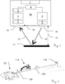
- Fig. 1 shows an embodiment of an optoelectronic distance meter 99 according to the invention as a block diagram. It may be, for example, a built-in observation device, battery-powered rangefinder, which can be used for targeting and determining target coordinates of a target object 11. However, the principle according to the invention can also be applied to other distance meters, for example in surveying equipment.
- the transmitting unit is shown and in the left half of the receiving unit.
- the separation of the two units described here is primarily functional and can (but does not have to) be constructed in the form of two physically separate units.
- Embodiments can be implemented in which both units are accommodated on a common printed circuit board, as are embodiments in which the components of the distance measurement are divided into a plurality of printed circuit boards, which are arranged spatially separated.
- a portion of the emitted radiation can also be guided as a reference beam 14 via a reference path of known length to the receiving unit. It can be provided for each of the reference beam 14 and the measuring beam 10 each own or a common receiving unit. When using a separate reference receiver, the receiving unit or parts thereof must be duplicated. It is also possible to switch over the beam guidance between reference 14 and measuring beam 10, for example by means of a reference deflection device which can be attached internally or externally. However, the inventive principle can also be applied to a rangefinder without an optical reference path.
- the transmit and receive beam 10 12 are shown at an unusually steep angle to each other.
- the transmit and receive beam paths are aligned such that they can be considered as approximately parallel to each other or intersect at a predetermined distance.
- Embodiments with special, angle-dependent distorting optics are also known at the receiver in order to be able to cover a wide distance range, especially at short distances.
- Embodiments with coaxial optical axes of the transmit and receive beam paths are also known, which can be achieved, for example, by mirroring the transmit beam 10 into the region of the center of the receive optical system 15.
- the rangefinder 99 is a block diagram of an exemplary internal structure of an embodiment of the transmitting and receiving unit is shown, which will now be discussed in detail.
- the illustration serves merely to explain an exemplary internal device structure, which can also be varied within the scope of practical embodiments of the principle according to the invention.
- the exemplary embodiment of the transmitting unit has a control processor 4 and a driver stage 5 for the light-emitting component 6, which converts the electrical signals of the driver stage 5 into electromagnetic radiation 10, 14.
- semiconductor light sources eg semiconductor lasers, semiconductor-pumped lasers or light-emitting diodes (LED) or other light sources can be used as the light emitter 6.
- the emitted light is collimated by an optic 16 into a directional beam 10 with low divergence.
- the driver stage 5 is adapted to the emission characteristics of the light source 6 in order to generate the intensity-modulated optical transmission radiation 10.
- the intensity of the emitted light signals 10 can be predetermined by the control unit 4, for example in a plurality of discrete stages or also continuously.
- Such a variation of the optical output power can be used, for example, to obtain a receive signal in an intensity range that can be evaluated by the receiver unit in accordance with the light component 12 returning from the target object 11 to the receiver 1.
- the advantageously evaluable intensity range can be defined, for example, as that range which exceeds a lower detectable limit of the receiving unit. but is below an upper saturation of the receiving unit.
- the intensity of the transmitted signal (e.g., stepwise or continuous) can be increased until a determination of the distance is possible.
- the emission power can be reduced until saturation of the input circuit no longer occurs. Since changing the emission power may also be accompanied by other, parasitic effects, the output power is often varied between discrete steps, for each of which at least partial compensation of the parasitic effects can be performed using calibration parameters.
- the driver stage 5 may include a control circuit for maintaining the desired optical transmission power, which is monitored, for example, with a monitor photodiode. Also, the laser driver stage 5 or its control for compliance with safety requirements, such as the eye safety guidelines, be formed.
- control processor 4 can be assigned to both the transmitting and the receiving unit and controls the processes for determining the distance. In other embodiments, a plurality of control processors 4 may be used, each of which may be special Take on subtasks.
- the control processor 4 may be, for example, a suitably programmed digital computer, such as a microprocessor or DSP. Alternatively, the control processor 4 or parts thereof may be implemented as FPGA, ASIC or with at least partially hard-wired logic.
- Block 7 represents the power supply of the rangefinder, which optionally contain not only supply filters but also voltage stabilization or regulation or a step-up or step-down converter.
- Power can be supplied by batteries, rechargeable batteries or other internal or external electrical energy sources.
- the receiving unit converts received electromagnetic radiation 12 with the receiving element 1 into an electrical signal.
- This can still be suitably conditioned in block 2 for further processing, for example by impedance conversion, filtering, amplifying, band limiting, heterodyne or homodyne mixing, etc.
- an input filter, a (transimpedance) amplifier, a mixer, a Sample & Hold module can be used. Member, etc. or even a combination of these may be present.
- the receiver 1 of the optical radiation 12 can use a photodiode as the receiving element, for example a PIN or an avalanche photodiode (APD) with a corresponding bias voltage.
- APD avalanche photodiode
- the conditioned received signal is digitized by an analog-to-digital converter 3, ie time and value quantified, and fed to a digital arithmetic unit 4 (a microprocessor, DSP, FPGA, ASIC, etc.) for further processing and determination of the distance.
- a digital arithmetic unit 4 a microprocessor, DSP, FPGA, ASIC, etc.
- the EDM system can be equipped with an additional external processor, microcontroller or DSP, which can perform special evaluation or interface tasks, for example the provision of a user interface or a communication interface.
- the signal-to-noise ratio of the received signal can also be improved.
- an increase is subject to physical limits, for example in the form of a maximum possible peak power of the drive circuit or of the light emitter.
- the components used are usually already operated in the upper range of their permissible characteristic values, so that a further increase in the output power is in many cases impractical or would involve higher costs.
- Higher drive pulses can also lead to increased electromagnetic emissions and / or thermal problems.
- An inventive extension of the pulse duration can also be used to improve the SNR, without having to interpret the transmission stage to higher peak powers.
- the longer pulse does not directly increase the value of the received signal, but a longer pulse with a lower Bandwidth are evaluated. However, this lower bandwidth provides better noise suppression (the noise term is approximately proportional to the square root of the bandwidth), which can improve the SNR from the other side, so to speak.
- the recorded noise bandwidth is also higher.
- the component costs, the evaluation effort, the power consumption, etc. increase with higher bandwidths and correspondingly higher measurement frequencies of the evaluation circuits, which is unacceptable for many applications, in particular mobile applications.
- An increase in the pulse amplitude can thus be the means of choice up to certain distances (or target reflectivities), but practically can not be arbitrarily scaled to very large ranges. Also can be associated with other disadvantages such as a higher power consumption or a longer measurement time, since only by superimposing a plurality of received signals for a measurement sufficiently large SNR can be achieved. In some applications, a fast, energy-saving measurement, or a larger measurement range can be preferred, even if it reduces the accuracy of measurement.
- the concept according to the invention also makes it possible to switch over between two or more operating modes with which the maximum range (or inversely the achievable measurement accuracy) can be selected on the finished device (even during the measurement).
- the EDM is improved by detecting a high range and making it accessible to a measurement.
- the measurable range of the EDM is thus improved, or the distance determination is made possible for a wide distance range of target objects.
- This is inventively achieved by the duration of the emitted light pulses is extended at larger measurement distances, which can be realized, for example, with an extension of the drive pulses of the light source.
- light or drive pulses of shorter duration are generated according to the invention, whereby a higher accuracy of the distance value determined by the EDM can be achieved than with the pulses with long pulse durations.
- a greater range of coverage can be covered, without thereby a lower measurement accuracy must be taken into account even in a measurement in the vicinity.
- a change of the operating mode in the transmitting unit can be performed, depending on the embodiment manually by the user or automatically by a control unit of the EDM, for example, due to characteristics of the received signals.
- Fig. 2 shows an exemplary use of a rangefinder 99 according to the invention in an observation device 19, which can be used for targeting a target object 11 and determining its distance 13 to the observer.
- the observation device has an observation direction which at least approximately coincides with the measurement direction of the distance measurement, so that a distance to an observed target point 11 can be determined with the rangefinder 99.
- a so-called goniometer so for example by inclination sensors in the observation device (or in a stand carrying the observation device) an inclination of the measuring direction relative to the horizontal can be determined, whereby, for example, a horizontal projection of the distance determined by the EDM 13 can be determined.
- an azimuthal measuring direction can be determined.
- the device can thus be used, for example, to determine geographical coordinates of the target object 11.
- observation device 19 is a short distance 13A to the vehicle 11A as a first target object with the emission of short light pulses with high measurement accuracy determined (symbolized by the short pulse shown in the measurement distance).
- the distance to the distant building 11B as a second target object can not be determined with the short pulse since the SNR of the measurement signal is too low. Therefore, the long distance 13B is detected with a pulse of long time duration (symbolized by the long pulse represented at the measurement distance). Even if in this case the achievable measurement accuracy is lower in comparison to the measurement with the short pulses, a measurement of this remote target 11B is thus at least possible. In some applications, less accurate measurement of distant targets is preferable to any measurement.
- the relative measurement accuracy based on the measured distance, can be improved over a measurement with a fixed pulse duration over the entire measuring range.
- the user of the observation device 19 can choose between two corresponding measuring modes for near or distant targets (or for high or low measuring accuracy) during the measuring operation.
- the measurement of short distances is performed with short pulse durations and the measurement of long distances is done with long pulse durations. If one considers the principle according to the invention from the side of the achievable measurement accuracy, then it is necessary to work through long pulses between an accurate measurement-with limited distance range-by short pulses and an inaccurate measurement-with extended distance range.
- the emission of pulses of longer durations is better suited to bridge large measuring distances.
- the peak signal intensity of the long pulse is not higher in comparison to a short pulse, more noise can be filtered out at a lower bandwidth, whereby the signal to be evaluated is above the detection limit of the receiver circuit or the signal evaluation during the long pulse.
- the signal energy of short pulses at long distances will not be enough to get the pulse out of the now broadband and correspondingly stronger one To evaluate noise so that it is no longer sufficiently detectable and thus no reliable distance determination is possible.
- a first mode of operation may be provided for near to medium ranges in which short pulses are emitted.
- This first mode is characterized by a limited range but high distance measurement accuracy.
- a second operating mode for distant targets in which pulses are emitted over a wider time period, although the measurement accuracy is lower than in the first mode, it is possible to achieve ranges there which may no longer be measurable in the first mode or due to the poor SNR are less accurate than in the second mode.
- This second mode is characterized by a maximum range but less distance measurement accuracy.
- the driver stage of the light source is designed in such a way that it can be generated by these drive pulses with a variable amplitude value and with a variable time duration, these two parameters being variable during the operation of the driver stage.
- the inventive principle can also be extended to more than two different pulse durations, for example, to a number of 3, 4, 5, 6, ... different pulse durations up to a quasi-continuous or continuous selection of the pulse durations.
- a number of 3, 4, 5, 6, ... different pulse durations up to a quasi-continuous or continuous selection of the pulse durations.
- the number of modes can thus be expanded as desired, from a selection of at least two modes each with discrete pulse widths to a continuous or quasi-continuous variation of the pulse width.
- the selection of the modes can be performed manually by the user, by the control electronics of the rangefinder or automatically based on the determined distance. For example, the user may select a mode based on his subjective estimate of the distance. According to the result of a first distance measurement experiment, the EDM may indicate to the user that as a result of characteristics of the received signal, a change of the mode would presumably lead to a better measurement result or automatically perform such a mode change and a new measurement attempt.
- Distance measurement functionality the distance measurement accuracy range considered useful.
- a distance measurement to millimeter accuracy makes little sense with a hand-held observation device, especially at measurement distances in the range of a hundred meters or a few kilometers. Greater observing and surveying of distant targets is a common task to be performed by such hand-held devices.
- a large measurement range which allows observation and measurement from a greater distance from a danger zone, is preferable. Examples include hunting operations, military or police operations, landmark navigation of pedestrians, land, air or water vehicles, etc. be.
- a possibility to change the pulse duration of the emission during the measuring operation allows the construction of a new generation of EDM devices in which the user has the possibility to choose whether an accurate distance measurement up to moderate measuring ranges or a less accurate distance measurement, but with maximum range - to be performed.
- Fig. 3a shows an exemplary illustration of pulse shapes, which are adjustable according to the invention in their pulse duration.
- Two stages of the pulse duration - short pulses 81 of duration T1 and long pulses 82 of duration T2 are shown by way of example.
- the pulse shape is shown here purely as an example in a sinusoidal manner and can also deviate from the illustrated form (eg Gaussian pulses, asymmetrically Gaussian pulses, rectangular pulses, trapezoidal pulses, Sinc pulses, etc.).
- the illustrated shape is the temporal intensity profile of the optical intensity of the emitted electromagnetic radiation, which results from the associated profile of the electrical drive signals of the light source 6 and the emission characteristic of the light source 6.
- the pulse duration can be defined for example by the time interval between the exceeding and falling below a predetermined relative amplitude threshold, for example 50%, 10%, 90%. Alternatively, the inclusion of a defined portion of the signal energy or the area under the curve can be used to define the pulse duration.
- the short and long pulses are shown directly one after the other, but in one embodiment according to the invention, either the short pulse duration 81 or the long pulse duration 82 may be selected depending on the active operating mode and only use this pulse duration, as described for example in US Pat Fig. 8 to Fig. 10 is shown.
- FIG. 8 Another embodiment is shown in which the pulse energy is reduced.
- the illustration shows short and long pulses with two different pulse amplitudes, each with the amplitude values 84A and 84C.
- Fig. 3b exemplifies another pulse shape, which can be achieved for example by a differently constructed driver circuit 5, as will be explained below. Again shown are short pulses 81 with a set pulse duration of T1 and long pulses 82 with a set pulse duration of T2, in this embodiment also the pulse amplitude in 3 stages 84A, 84B or 84C is adjustable.
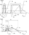
- Fig. 4 represents a transmission of short and long pulses, for example with a short pulse duration T1 of about 100ns and a long pulse duration T2 of about 400ns.
- the pulse durations mentioned here can also be chosen differently, in particular shorter. Also, the ratio of short to long pulse may be different.
- the signal amplitude of the two signals 81 and 82 is equal to the value 84 in each case.
- a band-limited representation of both signals is shown here.
- the noise level resulting from the filtering is shown at 74 for broadband filtering and at 75 for narrowband filtering.
- the amplitude value of the filtered signal 81H is sufficiently above the equivalent noise level 74 of the wideband filtering, whereby a distance determination is possible.
- Broadband filtering can be determined, for example, by the specified bandwidth of the receive circuitry hardware, especially the bandwidth of an analog front end.
- the resulting signal 81L would be below the associated noise level of the low-frequency filtering 75, whereby no distance determination would be possible.
- a broadband filtering of the long pulse 82 leads to the signal 82H, which compared to the signal 81H brings no significant advantages in terms of distance evaluation, but with respect to the achievable distance accuracy tends to be disadvantageous.
- the resulting SNR is not much better due to the approximately equal peak value.
- the signal strength is not better than that of the signal 81H, however, more noise is filtered out, resulting in an equivalent noise level 75.
- the signal-to-noise ratio has been improved in this case with long pulse duration T2 and narrow-band filtering 82L.
- Fig. 5 now shows the above principle of range improvement according to the invention by means of long pulse durations on an example in which a measurement with short pulses would not be possible.
- the short pulse 81 in the case of broadband filtering 81H, comes to lie below the noise level 74 resulting from the filtering, as a result of which no distance determination is possible.
- a narrow band filtered short pulse 81L would give even a lower signal.
- the recorded noise level 75 also decreases compared to that of the broadband evaluation 74.
- an SNR of greater than 1 can be achieved, which is characterized by the gray area. It is understandable to the person skilled in the art that the condition of an SNR> 1 given by way of example in the explanations should merely symbolize an evaluability of the signal. In practical embodiments, a higher or lower SNR value may well be used as the limit for the determinability of the distance, for example when additional additional methods (e.g., statistical averaging, signal accumulation, correlation reception, etc.) are used to improve the SNR.
- the pulse amplitude would have to be raised to about twice, as shown by the curves 85 and 85H. That in this case by the broadband evaluation, if appropriate, a high distance measurement accuracy could be achieved, is out of the question, however, any increase in the emission performance for various reasons (of which some are mentioned) is practically not always feasible. According to the above analysis, the distance range can be improved according to the invention with only weak return signals for low SNR.
- a further embodiment of a modification of the light pulses according to the invention is shown, in which transmission pulses superimposed with three different pulse lengths - are drawn - with a common emission time.
- the short pulses 81 (T1) are used for near target objects
- the medium pulse durations 82 (T2) for medium ranges
- the long pulse durations 83 (T3) for far-off target objects, with a longer maximum measurement distance being detectable for longer pulses.
- the three-fold graduation of the pulse duration T1, T2 and T3 is shown purely by way of example and can be formed in concrete embodiments of a two-stage to a (quasi) continuous adjustability of the pulse duration.
- FIG. 10 illustrates an embodiment in which a possible adjustment of a driver stage over the distance measurement range is illustrated.
- long pulses 83 are used for long distances, although with the low bandwidth in the evaluation of all modes, the lowest distance accuracy has the highest SNR.
- the pulse duration T2 is set and the bandwidth is increased during the evaluation - which improves the achievable measurement accuracy.
- a resulting reduction of the SNR - which at most brings with it a reduction of the maximum measurable range - can be accepted due to the sufficient received signals.
- the pulse 81C with a pulse duration of T1 can be used analogously.
- the full bandwidth of the receiver electronics used are used to determine the most accurate distance information.
- the received signal is sufficiently strong to obtain a sufficient SNR even with the resulting increased noise bandwidth.
- the received signal is too strong, for example due to highly reflective and / or very close target objects, it may to avoid saturation of the receiving circuitry - which would also complicate or impede accurate measurement - the amplitude of the transmit pulse may be reduced to that of 81B or 81A. Under special measurement circumstances, such a reduction of the amplitude can also be used for long pulses. As an example, this is the case of a multi-target measurement, such as a distance determination of a distant target through vegetation or a glass pane.
- the double arrow 80 symbolizes the change in the setting of the driver stage over the measuring distance used in this specific embodiment.
- the adjustment along this arrow can be done fully automatically based on the recorded measured values.
- the strategy used here eg arrow direction of the process at unknown distance
- this can also be done semi-automatically, for example by the user selecting between short or long range (ie the pulse duration) and the evaluation unit automatically adjusts the amplitude of the transmitted signal within this specification.
- the user may be requested to change the mode, if this appears advantageous to the evaluation unit on the basis of the received signals.
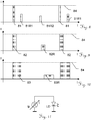
- Fig. 8 illustrates a continuous emission of single pulses 81 of short duration in a first operating mode with a relatively short maximum range but good distance measurement accuracy.
- the signal component 81R1 reflected by the target object follows shortly after the transmit pulse and has a relatively high intensity or signal strength. Due to the high signal strength, the received signal 81R1 can be evaluated with a high bandwidth and thus with correspondingly high temporal accuracy, which enables accurate distance determination.
- the in the evaluated signal also contained large noise bandwidth is not detrimental because, as I said, the useful signal is sufficiently large and thus the SNR meets the requirements for distance determination.
- Fig. 9 now illustrates an inventively increased pulse duration, wherein the amplitude value 84 is the same as in Fig. 5 is. Since the measuring distance is now greater, the time interval between the transmitting pulse 82 and the receiving pulse 82R is correspondingly greater and also the amplitude of the received pulse 82R is lower, while the transmitting pulse amplitude remains the same. As explained, by broadening the pulses and correspondingly adapting the bandwidth in the signal evaluation, it is still possible to achieve a sufficient SNR-or in other words, a larger maximum measurement distance. The pulses of Fig. 9 are therefore advantageous to use for large measuring distances, which with the pulses from Fig. 8 bad or impossible to measure. Although the achievable measurement accuracy with the long pulses is off Fig.
- the short pulses are advantageous for increased accuracy of the measured distance, but with one opposite to the pulses Fig. 6 more limited range of coverage.
- Fig. 10 represents a further embodiment of even longer pulses 83.
- the pulse amplitude 84 so the intensity of the emitted signal is the same as in FIGS. 8 and 9 ,
- the amplitude value of the pulses can also be adjustable.
- the pulse duration set even longer in this embodiment makes it possible to achieve even greater maximum distances than in Fig. 9 .
- at least two pulse durations, one goal close to a precise measurement, and one goal more inaccurate, are implemented.
- there are also three or more stages (for near, middle and far-end targets) as well as a continuous or quasi-continuous ( high-resolution discrete steps) setting options of the pulse durations according to embodiments of the invention.
- EDM electronic realization of an EDM, which operates according to the invention with different pulse durations, can be realized by the driver stage 5 by various circuit engineering approaches. Some exemplary examples will be explained with reference to the following figures.
- the embodiments shown here are not to be considered as exhaustive. Only basic circuits for providing the functionality according to the invention are shown. Practical circuitry implementations of the embodiments shown may, if appropriate, be extended in accordance with the general basic knowledge in electronic circuit design. The expert familiar with the field of electrical engineering can derive the corresponding mathematical representations of the circuit characteristics or determine them by numerical simulations in order to dimension component values in such a way that a sensor according to the invention can be dimensioned Result in the practical implementation is achieved. For example, in the circuits listed here, temperature compensation circuits or other circuits for reducing fault influences, backup capacitors, settings of operating points of components, etc. are not shown for the sake of clarity.
- a non-silicon laser such as a 1550 nm laser of equivalent power, accounts for many times the cost of an extended driver circuit in accordance with the present invention. Using a more powerful laser to extend the measurement range would require more effort compared to the present invention.
- Fig. 11 shows an exemplary general equivalent circuit diagram for a driver stage according to the invention for the emission of pulses with adjustable pulse duration according to the invention in the form of a current pulse output stage Ip with variable pulse duration t.
- Fig. 12 shows an exemplary circuit diagram of an embodiment of a driver stage according to the invention 5A for generating drive pulses with, in particular during their operation, adjustable pulse amplitude and adjustable pulse duration, with which a light source LD can be controlled in an EDM.
- a light source LD while a laser diode is shown, with other light sources such as light emitting diodes, etc. can be used. It may be at the light source also be a pumping light source of a laser.
- the driver stage 5A derives its energy in this illustration from the voltage source U, which may be embodied directly as a voltage source in the form of a battery or a rechargeable battery, but may also have other electronic circuit components, such as suppression capacitors, step-up or step-down converters, voltage stabilizers, etc.
- the capacitor C1 can be charged by the voltage source by means of the switch S1, and the capacitor C1 can be discharged via the light source LD by emitting a light pulse by means of the switch S3. If the switch S2 is closed, the capacitor C2 is connected in parallel with C1, and due to the thus higher total capacitance when closing the switch S3 emitted a light pulse longer period of time.
- Fig. 13 shows an exemplary circuit diagram of an embodiment of a driver stage according to the invention 5B an EDM transmitting unit.
- an alternative circuit technology solution for a connection of an additional capacity for pulse duration extension by the switch S2 is shown.
- a transmission unit according to the invention with a pulse output stage according to the invention which permits control of the amplitude values and the pulse duration of the pulses, permits the described exchange of measurement accuracy with respect to the measurement range by the user during or before the measurement in the field.
- an emission of short pulse widths with a higher distance measurement accuracy allows or provided an emission with long pulse durations with a higher range of distance measurement, between which can also be changed during the measurement operation.
- a pulse output stage according to the invention in which, for example, at least two pulse durations in the field can be set during or before a respective measurement allows a choice between "high accuracy of the measurements up to medium ranges ", or” medium accuracies at the highest possible measuring distance ". It can thus combine two worlds in one device design and there must be no compromises in the design phase of the device in this regard.
- the EDM may also automatically perform an automatic variation of the emission pulse duration based on the reflected signals (e.g., their intensity or a first coarse distance estimate or estimate).
- Fig. 14 shows an exemplary circuit diagram of an embodiment of a driver stage 5C according to the invention.
- the circuit part at the voltage source forms a kind of boost converter.
- the variation of the pulse duration is in turn realized by connecting a further capacitor C2 via the switch S1.
- Fig. 15 shows an exemplary circuit diagram of another embodiment of a driver stage according to the invention 5D, in which by different combinations the three switches S1, S2 S3 different transmission pulses are selectable.
- Fig. 16 shows an exemplary circuit diagram of another embodiment of a driver stage 5E according to the invention, in which by a non-complete discharge of a capacitor C » which has a higher capacitance value compared to the previous embodiments.
- the pulse duration is determined, wherein the capacitor C is not completely discharged, but keeps its voltage essentially constant during the pulse emission.
- the resulting pulse shape corresponds approximately to that Fig. 3b .
- the amplitude may be adjustable by varying the voltage U (indicated by the dashed arrow).
- two or more different pulse lengths may be set.
- the pulse amplitude may also be adjusted as needed, e.g. be designed adjustable by appropriate switch control or variation of the supply voltage. For example, with an adjustable drive voltage, the pulse amplitude and independently of this over a switch-on duration of the switch, the pulse width can be adjusted.
- power transistors for switching the often considerable drive currents in the driver circuits can be used in addition to the classical silicon power drivers such as bipolar or field effect transistors, for example, gallium arsenide or gallium nitride transistors.
Landscapes
- Engineering & Computer Science (AREA)
- Physics & Mathematics (AREA)
- General Physics & Mathematics (AREA)
- Radar, Positioning & Navigation (AREA)
- Remote Sensing (AREA)
- Computer Networks & Wireless Communication (AREA)
- Electromagnetism (AREA)
- Optical Radar Systems And Details Thereof (AREA)
Priority Applications (6)
| Application Number | Priority Date | Filing Date | Title |
|---|---|---|---|
| EP16167907.1A EP3171201B1 (fr) | 2012-03-07 | 2012-03-07 | Telemetre |
| EP12158382.7A EP2637038B1 (fr) | 2012-03-07 | 2012-03-07 | Appareil de mesure de distance |
| CA2808054A CA2808054C (fr) | 2012-03-07 | 2013-03-05 | Dispositif de mesure de distance |
| US13/788,986 US9103669B2 (en) | 2012-03-07 | 2013-03-07 | Distance measuring device |
| IL225082A IL225082A (en) | 2012-03-07 | 2013-03-07 | Distance measuring device |
| US14/818,124 US9683842B2 (en) | 2012-03-07 | 2015-08-04 | Distance measuring device |
Applications Claiming Priority (1)
| Application Number | Priority Date | Filing Date | Title |
|---|---|---|---|
| EP12158382.7A EP2637038B1 (fr) | 2012-03-07 | 2012-03-07 | Appareil de mesure de distance |
Related Child Applications (2)
| Application Number | Title | Priority Date | Filing Date |
|---|---|---|---|
| EP16167907.1A Division EP3171201B1 (fr) | 2012-03-07 | 2012-03-07 | Telemetre |
| EP16167907.1A Division-Into EP3171201B1 (fr) | 2012-03-07 | 2012-03-07 | Telemetre |
Publications (2)
| Publication Number | Publication Date |
|---|---|
| EP2637038A1 true EP2637038A1 (fr) | 2013-09-11 |
| EP2637038B1 EP2637038B1 (fr) | 2017-01-18 |
Family
ID=48916400
Family Applications (2)
| Application Number | Title | Priority Date | Filing Date |
|---|---|---|---|
| EP16167907.1A Active EP3171201B1 (fr) | 2012-03-07 | 2012-03-07 | Telemetre |
| EP12158382.7A Active EP2637038B1 (fr) | 2012-03-07 | 2012-03-07 | Appareil de mesure de distance |
Family Applications Before (1)
| Application Number | Title | Priority Date | Filing Date |
|---|---|---|---|
| EP16167907.1A Active EP3171201B1 (fr) | 2012-03-07 | 2012-03-07 | Telemetre |
Country Status (4)
| Country | Link |
|---|---|
| US (2) | US9103669B2 (fr) |
| EP (2) | EP3171201B1 (fr) |
| CA (1) | CA2808054C (fr) |
| IL (1) | IL225082A (fr) |
Cited By (11)
| Publication number | Priority date | Publication date | Assignee | Title |
|---|---|---|---|---|
| EP3070494A1 (fr) * | 2015-03-18 | 2016-09-21 | Leica Geosystems AG | Procédé de télémétrie électro-optique et télémètre associé |
| WO2017178711A1 (fr) * | 2016-04-13 | 2017-10-19 | Oulun Yliopisto | Dispositif de mesure de distance et émetteur, récepteur et procédé associés |
| EP3264544A1 (fr) * | 2016-06-28 | 2018-01-03 | ams AG | Circuit de commande pour générer une impulsion de signal de fonctionnement d'une diode électroluminescente |
| DE102016224509A1 (de) * | 2016-12-08 | 2018-06-14 | Zf Friedrichshafen Ag | Empfängeranordnung und Verfahren zum Empfang wenigstens eines Lichtimpulses und zur Ausgabe eines Empfangssignals |
| DE102016225411A1 (de) * | 2016-12-19 | 2018-06-21 | Robert Bosch Gmbh | Laserentfernungsmesser |
| CN108931778A (zh) * | 2017-05-27 | 2018-12-04 | 艾普瑞(上海)精密光电有限公司 | 一种共轴测距望远镜及其测距方法 |
| US20200256954A1 (en) * | 2019-02-07 | 2020-08-13 | Analog Devices, Inc. | Optical pulse coding in a lidar system |
| WO2021074081A1 (fr) * | 2019-10-15 | 2021-04-22 | Robert Bosch Gmbh | Procédé de génération d'impulsions lumineuses d'un système lidar |
| US11047966B2 (en) | 2016-08-17 | 2021-06-29 | Advanced New Technologies Co., Ltd. | Method for determining change in distance, location prompting method and apparatus and system thereof |
| WO2022096167A1 (fr) * | 2020-11-03 | 2022-05-12 | Mercedes-Benz Group AG | Procédé de détermination d'un changement de portée d'un capteur lidar |
| DE102022115374A1 (de) | 2022-06-21 | 2023-12-21 | Blickfeld GmbH | System und Verfahren zum Erzeugen von Laufzeitmessungspulsen |
Families Citing this family (90)
| Publication number | Priority date | Publication date | Assignee | Title |
|---|---|---|---|---|
| WO2015176953A1 (fr) | 2014-05-23 | 2015-11-26 | Koninklijke Philips N.V. | Système et procédé de détection d'objets |
| US9575184B2 (en) * | 2014-07-03 | 2017-02-21 | Continental Advanced Lidar Solutions Us, Inc. | LADAR sensor for a dense environment |
| JP6438321B2 (ja) * | 2015-02-23 | 2018-12-12 | 古野電気株式会社 | レーダ装置 |
| US10419655B2 (en) | 2015-04-27 | 2019-09-17 | Snap-Aid Patents Ltd. | Estimating and using relative head pose and camera field-of-view |
| JP2017009339A (ja) * | 2015-06-18 | 2017-01-12 | 株式会社リコー | センサ、センシング装置及び距離計測方法 |
| US9880267B2 (en) * | 2015-09-04 | 2018-01-30 | Microvision, Inc. | Hybrid data acquisition in scanned beam display |
| US10557939B2 (en) | 2015-10-19 | 2020-02-11 | Luminar Technologies, Inc. | Lidar system with improved signal-to-noise ratio in the presence of solar background noise |
| EP3371625A4 (fr) | 2015-11-05 | 2019-05-15 | Luminar Technologies, Inc. | Système lidar avec vitesse de balayage améliorée pour cartographie de profondeur haute résolution |
| US10557940B2 (en) | 2015-11-30 | 2020-02-11 | Luminar Technologies, Inc. | Lidar system |
| US10627490B2 (en) | 2016-01-31 | 2020-04-21 | Velodyne Lidar, Inc. | Multiple pulse, LIDAR based 3-D imaging |
| US11255663B2 (en) | 2016-03-04 | 2022-02-22 | May Patents Ltd. | Method and apparatus for cooperative usage of multiple distance meters |
| US10048374B2 (en) * | 2016-03-21 | 2018-08-14 | Velodyne Lidar, Inc. | LIDAR based 3-D imaging with varying pulse repetition |
| CN105759279B (zh) * | 2016-04-20 | 2018-06-01 | 深圳市速腾聚创科技有限公司 | 一种基于波形时域匹配的激光测距系统及方法 |
| WO2017210418A1 (fr) | 2016-06-01 | 2017-12-07 | Velodyne Lidar, Inc. | Lidar à balayage à pixels multiples |
| JP6980369B2 (ja) * | 2016-07-29 | 2021-12-15 | パイオニア株式会社 | 光源駆動装置および距離測定装置 |
| JP2022016541A (ja) * | 2016-07-29 | 2022-01-21 | パイオニア株式会社 | 光源駆動装置 |
| JP2018059839A (ja) * | 2016-10-06 | 2018-04-12 | 株式会社デンソー | 距離測定装置 |
| US10942257B2 (en) | 2016-12-31 | 2021-03-09 | Innovusion Ireland Limited | 2D scanning high precision LiDAR using combination of rotating concave mirror and beam steering devices |
| US9905992B1 (en) | 2017-03-16 | 2018-02-27 | Luminar Technologies, Inc. | Self-Raman laser for lidar system |
| US9810775B1 (en) | 2017-03-16 | 2017-11-07 | Luminar Technologies, Inc. | Q-switched laser for LIDAR system |
| US9810786B1 (en) | 2017-03-16 | 2017-11-07 | Luminar Technologies, Inc. | Optical parametric oscillator for lidar system |
| US9869754B1 (en) | 2017-03-22 | 2018-01-16 | Luminar Technologies, Inc. | Scan patterns for lidar systems |
| US10114111B2 (en) | 2017-03-28 | 2018-10-30 | Luminar Technologies, Inc. | Method for dynamically controlling laser power |
| US10209359B2 (en) | 2017-03-28 | 2019-02-19 | Luminar Technologies, Inc. | Adaptive pulse rate in a lidar system |
| US10139478B2 (en) | 2017-03-28 | 2018-11-27 | Luminar Technologies, Inc. | Time varying gain in an optical detector operating in a lidar system |
| US10545240B2 (en) | 2017-03-28 | 2020-01-28 | Luminar Technologies, Inc. | LIDAR transmitter and detector system using pulse encoding to reduce range ambiguity |
| US10732281B2 (en) | 2017-03-28 | 2020-08-04 | Luminar Technologies, Inc. | Lidar detector system having range walk compensation |
| US10254388B2 (en) | 2017-03-28 | 2019-04-09 | Luminar Technologies, Inc. | Dynamically varying laser output in a vehicle in view of weather conditions |
| US10007001B1 (en) | 2017-03-28 | 2018-06-26 | Luminar Technologies, Inc. | Active short-wave infrared four-dimensional camera |
| US10061019B1 (en) | 2017-03-28 | 2018-08-28 | Luminar Technologies, Inc. | Diffractive optical element in a lidar system to correct for backscan |
| US10267899B2 (en) | 2017-03-28 | 2019-04-23 | Luminar Technologies, Inc. | Pulse timing based on angle of view |
| US10121813B2 (en) | 2017-03-28 | 2018-11-06 | Luminar Technologies, Inc. | Optical detector having a bandpass filter in a lidar system |
| US11119198B2 (en) | 2017-03-28 | 2021-09-14 | Luminar, Llc | Increasing operational safety of a lidar system |
| US10976417B2 (en) | 2017-03-29 | 2021-04-13 | Luminar Holdco, Llc | Using detectors with different gains in a lidar system |
| US10254762B2 (en) | 2017-03-29 | 2019-04-09 | Luminar Technologies, Inc. | Compensating for the vibration of the vehicle |
| US10641874B2 (en) | 2017-03-29 | 2020-05-05 | Luminar Technologies, Inc. | Sizing the field of view of a detector to improve operation of a lidar system |
| US10663595B2 (en) | 2017-03-29 | 2020-05-26 | Luminar Technologies, Inc. | Synchronized multiple sensor head system for a vehicle |
| US10983213B2 (en) | 2017-03-29 | 2021-04-20 | Luminar Holdco, Llc | Non-uniform separation of detector array elements in a lidar system |
| US11002853B2 (en) | 2017-03-29 | 2021-05-11 | Luminar, Llc | Ultrasonic vibrations on a window in a lidar system |
| US10088559B1 (en) | 2017-03-29 | 2018-10-02 | Luminar Technologies, Inc. | Controlling pulse timing to compensate for motor dynamics |
| US10969488B2 (en) | 2017-03-29 | 2021-04-06 | Luminar Holdco, Llc | Dynamically scanning a field of regard using a limited number of output beams |
| US11181622B2 (en) | 2017-03-29 | 2021-11-23 | Luminar, Llc | Method for controlling peak and average power through laser receiver |
| US10191155B2 (en) | 2017-03-29 | 2019-01-29 | Luminar Technologies, Inc. | Optical resolution in front of a vehicle |
| US10401481B2 (en) | 2017-03-30 | 2019-09-03 | Luminar Technologies, Inc. | Non-uniform beam power distribution for a laser operating in a vehicle |
| US10241198B2 (en) | 2017-03-30 | 2019-03-26 | Luminar Technologies, Inc. | Lidar receiver calibration |
| US9989629B1 (en) | 2017-03-30 | 2018-06-05 | Luminar Technologies, Inc. | Cross-talk mitigation using wavelength switching |
| US10684360B2 (en) | 2017-03-30 | 2020-06-16 | Luminar Technologies, Inc. | Protecting detector in a lidar system using off-axis illumination |
| US10295668B2 (en) | 2017-03-30 | 2019-05-21 | Luminar Technologies, Inc. | Reducing the number of false detections in a lidar system |
| CA3057988A1 (fr) | 2017-03-31 | 2018-10-04 | Velodyne Lidar, Inc. | Commande de puissance d'eclairage a lidar integre |
| US20180284246A1 (en) | 2017-03-31 | 2018-10-04 | Luminar Technologies, Inc. | Using Acoustic Signals to Modify Operation of a Lidar System |
| US11022688B2 (en) | 2017-03-31 | 2021-06-01 | Luminar, Llc | Multi-eye lidar system |
| US10677897B2 (en) | 2017-04-14 | 2020-06-09 | Luminar Technologies, Inc. | Combining lidar and camera data |
| US20180306927A1 (en) * | 2017-04-21 | 2018-10-25 | GM Global Technology Operations LLC | Method and apparatus for pulse repetition sequence with high processing gain |
| JP2020519881A (ja) | 2017-05-08 | 2020-07-02 | ベロダイン ライダー, インク. | Lidarデータ収集及び制御 |
| WO2018211831A1 (fr) * | 2017-05-18 | 2018-11-22 | シャープ株式会社 | Détecteur optique et équipement électronique portable |
| DE102017216198A1 (de) * | 2017-09-13 | 2019-03-14 | Osram Gmbh | Datenübermittlung mit einem kraftfahrzeug |
| US10003168B1 (en) | 2017-10-18 | 2018-06-19 | Luminar Technologies, Inc. | Fiber laser with free-space components |
| US10324185B2 (en) | 2017-11-22 | 2019-06-18 | Luminar Technologies, Inc. | Reducing audio noise in a lidar scanner with a polygon mirror |
| US10451716B2 (en) | 2017-11-22 | 2019-10-22 | Luminar Technologies, Inc. | Monitoring rotation of a mirror in a lidar system |
| JP6973506B2 (ja) * | 2017-12-15 | 2021-12-01 | 日本電気株式会社 | 測距装置及び制御方法 |
| JP7294139B2 (ja) * | 2017-12-15 | 2023-06-20 | コニカミノルタ株式会社 | 距離測定装置、距離測定装置の制御方法、および距離測定装置の制御プログラム |
| US11493601B2 (en) | 2017-12-22 | 2022-11-08 | Innovusion, Inc. | High density LIDAR scanning |
| US11340339B2 (en) | 2017-12-22 | 2022-05-24 | Waymo Llc | Systems and methods for adaptive range coverage using LIDAR |
| WO2020013890A2 (fr) | 2018-02-23 | 2020-01-16 | Innovusion Ireland Limited | Orientation d'impulsions à longueurs d'onde multiples dans des systèmes lidar |
| WO2019165294A1 (fr) | 2018-02-23 | 2019-08-29 | Innovusion Ireland Limited | Système de direction bidimensionnelle de systèmes lidar |
| US10324170B1 (en) | 2018-04-05 | 2019-06-18 | Luminar Technologies, Inc. | Multi-beam lidar system with polygon mirror |
| US11029406B2 (en) | 2018-04-06 | 2021-06-08 | Luminar, Llc | Lidar system with AlInAsSb avalanche photodiode |
| DE102018111218A1 (de) * | 2018-05-09 | 2019-11-14 | Pepperl+Fuchs Gmbh | Verfahren und optoelektronischer Sensor zum Messen einer Entfernung von Objekten |
| US10348051B1 (en) | 2018-05-18 | 2019-07-09 | Luminar Technologies, Inc. | Fiber-optic amplifier |
| US10591601B2 (en) | 2018-07-10 | 2020-03-17 | Luminar Technologies, Inc. | Camera-gated lidar system |
| US10627516B2 (en) * | 2018-07-19 | 2020-04-21 | Luminar Technologies, Inc. | Adjustable pulse characteristics for ground detection in lidar systems |
| US10551501B1 (en) | 2018-08-09 | 2020-02-04 | Luminar Technologies, Inc. | Dual-mode lidar system |
| US10340651B1 (en) | 2018-08-21 | 2019-07-02 | Luminar Technologies, Inc. | Lidar system with optical trigger |
| JP7499558B2 (ja) * | 2018-08-29 | 2024-06-14 | 京セラ株式会社 | 電子機器、電子機器の制御方法、及び電子機器の制御プログラム |
| US10708514B2 (en) | 2018-08-30 | 2020-07-07 | Analog Devices, Inc. | Blending depth images obtained with multiple exposures |
| US10712434B2 (en) | 2018-09-18 | 2020-07-14 | Velodyne Lidar, Inc. | Multi-channel LIDAR illumination driver |
| DE102018221083A1 (de) | 2018-12-06 | 2020-06-10 | Robert Bosch Gmbh | LiDAR-System sowie Kraftfahrzeug |
| WO2020139381A1 (fr) * | 2018-12-26 | 2020-07-02 | Didi Research America, Llc | Système et procédés destinés à des opérations de télémétrie à l'aide de multiples signaux |
| US11885958B2 (en) | 2019-01-07 | 2024-01-30 | Velodyne Lidar Usa, Inc. | Systems and methods for a dual axis resonant scanning mirror |
| US11774561B2 (en) | 2019-02-08 | 2023-10-03 | Luminar Technologies, Inc. | Amplifier input protection circuits |
| EP3783308B1 (fr) * | 2019-08-19 | 2024-01-10 | Leica Geosystems AG | Système géodésique |
| DE102019215835A1 (de) * | 2019-10-15 | 2021-04-15 | Robert Bosch Gmbh | Erweiterung eines Dynamikbereichs von SPAD-basierten Detektoren |
| US12025702B2 (en) | 2019-11-29 | 2024-07-02 | Waymo Llc | Retroreflector detection and avoidance in a LIDAR device |
| JP7068364B2 (ja) * | 2020-03-02 | 2022-05-16 | 三菱電機株式会社 | 物体検知装置 |
| US20220003859A1 (en) * | 2020-07-01 | 2022-01-06 | Qualcomm Incorporated | Monostatic radar with progressive length transmission |
| US12105200B2 (en) * | 2020-10-30 | 2024-10-01 | Waymo Llc | Detecting retroreflectors in NIR images to control LIDAR scan |
| US12061291B2 (en) * | 2021-01-11 | 2024-08-13 | Beijing Voyager Technology Co., Ltd. | Systems and methods for controlling laser power in light detection and ranging (LiDAR) systems |
| FR3119683B1 (fr) | 2021-02-10 | 2024-03-08 | Bertin Technologies Sa | Système et procédé d’observation et procédé de fabrication d’un tel système |
| DE102021202234A1 (de) | 2021-03-09 | 2022-09-15 | Robert Bosch Gesellschaft mit beschränkter Haftung | LiDAR-System zur Entfernungsbestimmung von Objekten |
| CN118274730B (zh) * | 2024-03-28 | 2024-09-20 | 淮阴师范学院 | 用于测定距离的光学测量系统 |
Citations (12)
| Publication number | Priority date | Publication date | Assignee | Title |
|---|---|---|---|---|
| US3628048A (en) | 1967-04-03 | 1971-12-14 | Santa Barbara Res Center | High current pulsing arrangement to energize coherent radiation source |
| DE2331084A1 (de) | 1972-07-03 | 1974-01-24 | Bofors Ab | Verfahren und vorrichtung zum pumpen von diodenlasern |
| WO1997022179A1 (fr) | 1995-12-13 | 1997-06-19 | Leica Ag | Circuit pour l'alimentation d'un etage de sortie d'impulsions |
| DE19943127C1 (de) | 1999-09-09 | 2001-03-22 | Heller Elektronik Kg Dr | Vorrichtung und Verfahren zum Erzeugen eines kurzen Strompulses |
| US6310682B1 (en) * | 1999-07-06 | 2001-10-30 | Quarton, Inc. | System and method for laser range finder |
| US20020131034A1 (en) * | 2001-03-15 | 2002-09-19 | Asia Optical Co., Inc. | High precision laser range finder with an automatic peak control loop |
| WO2006063740A1 (fr) | 2004-12-18 | 2006-06-22 | Leica Geosystems Ag | Procede de mesure de distance heterodyne a un seul canal |
| US20070024841A1 (en) * | 2005-07-13 | 2007-02-01 | Mariusz Kloza | Device for precise distance measurement |
| WO2007022927A1 (fr) | 2005-08-24 | 2007-03-01 | Leica Geosystems Ag | Procede de mesure de la distance a plusieurs cibles fonctionnant selon le principe de la mesure de phase |
| US20090059201A1 (en) * | 2007-08-28 | 2009-03-05 | Science Applications International Corporation | Full-Field Light Detection and Ranging Imaging System |
| US20090273770A1 (en) * | 2008-04-30 | 2009-11-05 | Honeywell International Inc. | Systems and methods for safe laser imaging, detection and ranging (lidar) operation |
| WO2009156580A1 (fr) * | 2008-06-27 | 2009-12-30 | Oulun Yliopisto | Procédé et dispositif pour mesurer une distance |
Family Cites Families (9)
| Publication number | Priority date | Publication date | Assignee | Title |
|---|---|---|---|---|
| JPS5454029A (en) * | 1977-10-06 | 1979-04-27 | Canon Inc | Light varying strobo camera of program type |
| US6133989A (en) * | 1993-02-09 | 2000-10-17 | Advanced Scientific Concepts, Inc. | 3D imaging laser radar |
| US5303248A (en) * | 1993-03-01 | 1994-04-12 | Litton Systems, Inc. | Laser apparatus and method employing digital filter controlled pulse width modulation |
| US5638163A (en) * | 1995-06-07 | 1997-06-10 | Hughes Electronics | Low cost laser range finder system architecture |
| DE10143107A1 (de) * | 2001-09-03 | 2003-03-20 | Sick Ag | Optoelektronische Entfernungsmeßeinrichtung |
| EP1860462A1 (fr) * | 2006-05-23 | 2007-11-28 | Leica Geosystems AG | Procédé de mesure de distances et appareil de mesure de distances destinés à l'enregistrement des dimensions spatiales d'une cible |
| TWI333542B (en) * | 2007-06-25 | 2010-11-21 | Asia Optical Co Inc | Laser rangefinder and method for digital signal processing thereof |
| US7945408B2 (en) * | 2007-09-20 | 2011-05-17 | Voxis, Inc. | Time delay estimation |
| CA2781237C (fr) * | 2009-12-22 | 2016-02-23 | Leica Geosystems Ag | Dispositif de mesure tres precise d'une distance |
-
2012
- 2012-03-07 EP EP16167907.1A patent/EP3171201B1/fr active Active
- 2012-03-07 EP EP12158382.7A patent/EP2637038B1/fr active Active
-
2013
- 2013-03-05 CA CA2808054A patent/CA2808054C/fr active Active
- 2013-03-07 US US13/788,986 patent/US9103669B2/en active Active
- 2013-03-07 IL IL225082A patent/IL225082A/en active IP Right Grant
-
2015
- 2015-08-04 US US14/818,124 patent/US9683842B2/en active Active
Patent Citations (12)
| Publication number | Priority date | Publication date | Assignee | Title |
|---|---|---|---|---|
| US3628048A (en) | 1967-04-03 | 1971-12-14 | Santa Barbara Res Center | High current pulsing arrangement to energize coherent radiation source |
| DE2331084A1 (de) | 1972-07-03 | 1974-01-24 | Bofors Ab | Verfahren und vorrichtung zum pumpen von diodenlasern |
| WO1997022179A1 (fr) | 1995-12-13 | 1997-06-19 | Leica Ag | Circuit pour l'alimentation d'un etage de sortie d'impulsions |
| US6310682B1 (en) * | 1999-07-06 | 2001-10-30 | Quarton, Inc. | System and method for laser range finder |
| DE19943127C1 (de) | 1999-09-09 | 2001-03-22 | Heller Elektronik Kg Dr | Vorrichtung und Verfahren zum Erzeugen eines kurzen Strompulses |
| US20020131034A1 (en) * | 2001-03-15 | 2002-09-19 | Asia Optical Co., Inc. | High precision laser range finder with an automatic peak control loop |
| WO2006063740A1 (fr) | 2004-12-18 | 2006-06-22 | Leica Geosystems Ag | Procede de mesure de distance heterodyne a un seul canal |
| US20070024841A1 (en) * | 2005-07-13 | 2007-02-01 | Mariusz Kloza | Device for precise distance measurement |
| WO2007022927A1 (fr) | 2005-08-24 | 2007-03-01 | Leica Geosystems Ag | Procede de mesure de la distance a plusieurs cibles fonctionnant selon le principe de la mesure de phase |
| US20090059201A1 (en) * | 2007-08-28 | 2009-03-05 | Science Applications International Corporation | Full-Field Light Detection and Ranging Imaging System |
| US20090273770A1 (en) * | 2008-04-30 | 2009-11-05 | Honeywell International Inc. | Systems and methods for safe laser imaging, detection and ranging (lidar) operation |
| WO2009156580A1 (fr) * | 2008-06-27 | 2009-12-30 | Oulun Yliopisto | Procédé et dispositif pour mesurer une distance |
Cited By (21)
| Publication number | Priority date | Publication date | Assignee | Title |
|---|---|---|---|---|
| US10451736B2 (en) | 2015-03-18 | 2019-10-22 | Leica Geosystems Ag | Electro-optical distance measurement method and equivalent distance meter |
| EP3070494A1 (fr) * | 2015-03-18 | 2016-09-21 | Leica Geosystems AG | Procédé de télémétrie électro-optique et télémètre associé |
| WO2017178711A1 (fr) * | 2016-04-13 | 2017-10-19 | Oulun Yliopisto | Dispositif de mesure de distance et émetteur, récepteur et procédé associés |
| US11300666B2 (en) | 2016-04-13 | 2022-04-12 | Oulun Yliopisto | Distance measuring device and transmitter, receiver and method thereof |
| WO2018001701A1 (fr) * | 2016-06-28 | 2018-01-04 | Ams Ag | Circuit d'attaque permettant de générer une impulsion de signal pour faire fonctionner une diode électroluminescente |
| CN109417273A (zh) * | 2016-06-28 | 2019-03-01 | ams有限公司 | 生成信号脉冲以用于操作发光二极管的驱动电路 |
| US11294055B2 (en) | 2016-06-28 | 2022-04-05 | Ams Ag | Driving circuit to generate a signal pulse for operating a light-emitting diode |
| EP3264544A1 (fr) * | 2016-06-28 | 2018-01-03 | ams AG | Circuit de commande pour générer une impulsion de signal de fonctionnement d'une diode électroluminescente |
| US11366209B2 (en) | 2016-08-17 | 2022-06-21 | Advanced New Technologies Co., Ltd. | Method for determining change in distance, location prompting method and apparatus and system thereof |
| US11047966B2 (en) | 2016-08-17 | 2021-06-29 | Advanced New Technologies Co., Ltd. | Method for determining change in distance, location prompting method and apparatus and system thereof |
| DE102016224509A1 (de) * | 2016-12-08 | 2018-06-14 | Zf Friedrichshafen Ag | Empfängeranordnung und Verfahren zum Empfang wenigstens eines Lichtimpulses und zur Ausgabe eines Empfangssignals |
| DE102016225411A1 (de) * | 2016-12-19 | 2018-06-21 | Robert Bosch Gmbh | Laserentfernungsmesser |
| CN108205126A (zh) * | 2016-12-19 | 2018-06-26 | 罗伯特·博世有限公司 | 激光测距器 |
| CN108205126B (zh) * | 2016-12-19 | 2024-06-25 | 罗伯特·博世有限公司 | 激光测距器 |
| CN108931778A (zh) * | 2017-05-27 | 2018-12-04 | 艾普瑞(上海)精密光电有限公司 | 一种共轴测距望远镜及其测距方法 |
| US20200256954A1 (en) * | 2019-02-07 | 2020-08-13 | Analog Devices, Inc. | Optical pulse coding in a lidar system |
| WO2021074081A1 (fr) * | 2019-10-15 | 2021-04-22 | Robert Bosch Gmbh | Procédé de génération d'impulsions lumineuses d'un système lidar |
| WO2022096167A1 (fr) * | 2020-11-03 | 2022-05-12 | Mercedes-Benz Group AG | Procédé de détermination d'un changement de portée d'un capteur lidar |
| KR20230051607A (ko) * | 2020-11-03 | 2023-04-18 | 메르세데스-벤츠 그룹 아게 | 라이다 센서의 검출 범위 변화를 산출하는 방법 |
| US12019191B2 (en) | 2020-11-03 | 2024-06-25 | Mercedes-Benz Group AG | Method for identifying a change of a range of a lidar sensor |
| DE102022115374A1 (de) | 2022-06-21 | 2023-12-21 | Blickfeld GmbH | System und Verfahren zum Erzeugen von Laufzeitmessungspulsen |
Also Published As
| Publication number | Publication date |
|---|---|
| CA2808054A1 (fr) | 2013-09-07 |
| IL225082A0 (en) | 2013-06-27 |
| IL225082A (en) | 2017-02-28 |
| EP3171201B1 (fr) | 2018-05-09 |
| EP3171201A1 (fr) | 2017-05-24 |
| US20130235366A1 (en) | 2013-09-12 |
| US9103669B2 (en) | 2015-08-11 |
| EP2637038B1 (fr) | 2017-01-18 |
| US9683842B2 (en) | 2017-06-20 |
| US20150346325A1 (en) | 2015-12-03 |
| CA2808054C (fr) | 2016-10-18 |
Similar Documents
| Publication | Publication Date | Title |
|---|---|---|
| EP2637038B1 (fr) | Appareil de mesure de distance | |
| EP2597483B1 (fr) | Appareil de mesure de distance | |
| EP2475957B2 (fr) | Télémètre optique | |
| EP1311873B1 (fr) | Procede et dispositif de mesure des distances | |
| EP2240797B1 (fr) | Dispositif de mesure de distance optoélectronique | |
| EP2843440B1 (fr) | Mesure de distance stabilisée dans un appareil d'observation | |
| DE69620674T2 (de) | Architektur für kostengünstiges Laserentfernungsmessersystem | |
| EP1595110B1 (fr) | Procede et dispositif d'extraction d'informations geodesiques de distance | |
| WO2003016944A2 (fr) | Procede et dispositif pour acquerir une image telemetrique tridimensionnelle | |
| EP1529194B1 (fr) | Procede et dispositif de mesure optique de distance | |
| DE102012021831A1 (de) | Abtastende optoelektronische Detektionseinrichtung mit einer Detektionsschwelle, Kraftfahrzeg und entsprechendes Verfahren | |
| DE102007046562A1 (de) | Verfahren und Vorrichtung zum Bestimmen eines Abstands mittels eines optoelektronischen Bildsensors | |
| EP1927821B1 (fr) | Dispositif et procede de telemetrie | |
| DE19643287A1 (de) | Verfahren und Vorrichtung zur Kalibrierung von Entfernungsmeßgeräten | |
| EP1825294A1 (fr) | Procede de mesure de distance heterodyne a un seul canal | |
| DE102011005740A1 (de) | Messvorrichtung zur Messung einer Entfernung zwischen der Messvorrichtung und einem Zielobjekt mit Hilfe optischer Messstrahlung | |
| DE102009029372A1 (de) | Messvorrichtung zur Messung einer Entfernung zwischen der Messvorrichtung und einem Zielobjekt mit Hilfe optischer Messstrahlung | |
| DE102006013292A1 (de) | Vorrichtung zur optischen Distanzmessung | |
| EP1789754A1 (fr) | Dispositif et procede de mesure de distance optique | |
| DE212017000247U1 (de) | LiDAR-Vorrichtung | |
| DE102016124197A1 (de) | Verfahren zur Abstandsmessung, Empfangseinrichtung einer Abstandsmessvorrichtung, Abstandsmessvorrichtung und Fahrerassistenzsystem | |
| EP2182379B1 (fr) | Scanner laser mesurant l'éloignement | |
| DE2257445B2 (de) | Visuell ausrichtbarer elektrooptischer laufzeit-entfernungsmesser mit intensitaetssteuerung | |
| EP3543648A1 (fr) | Appareil de mesure optoélectronique à fonctionnalité de balayage | |
| DE10153742A1 (de) | Verfahren und Vorrichtung zur Aufnahme eines dreidimensionalen Abstandsbildes |
Legal Events
| Date | Code | Title | Description |
|---|---|---|---|
| PUAI | Public reference made under article 153(3) epc to a published international application that has entered the european phase |
Free format text: ORIGINAL CODE: 0009012 |
|
| AK | Designated contracting states |
Kind code of ref document: A1 Designated state(s): AL AT BE BG CH CY CZ DE DK EE ES FI FR GB GR HR HU IE IS IT LI LT LU LV MC MK MT NL NO PL PT RO RS SE SI SK SM TR |
|
| AX | Request for extension of the european patent |
Extension state: BA ME |
|
| 17P | Request for examination filed |
Effective date: 20130828 |
|
| RBV | Designated contracting states (corrected) |
Designated state(s): AL AT BE BG CH CY CZ DE DK EE ES FI FR GB GR HR HU IE IS IT LI LT LU LV MC MK MT NL NO PL PT RO RS SE SI SK SM TR |
|
| RIC1 | Information provided on ipc code assigned before grant |
Ipc: G01S 7/486 20060101ALI20160111BHEP Ipc: G01S 17/10 20060101AFI20160111BHEP Ipc: G01S 7/484 20060101ALI20160111BHEP Ipc: G01C 3/08 20060101ALI20160111BHEP |
|
| 17Q | First examination report despatched |
Effective date: 20160128 |
|
| GRAP | Despatch of communication of intention to grant a patent |
Free format text: ORIGINAL CODE: EPIDOSNIGR1 |
|
| INTG | Intention to grant announced |
Effective date: 20161011 |
|
| GRAS | Grant fee paid |
Free format text: ORIGINAL CODE: EPIDOSNIGR3 |
|
| GRAA | (expected) grant |
Free format text: ORIGINAL CODE: 0009210 |
|
| AK | Designated contracting states |
Kind code of ref document: B1 Designated state(s): AL AT BE BG CH CY CZ DE DK EE ES FI FR GB GR HR HU IE IS IT LI LT LU LV MC MK MT NL NO PL PT RO RS SE SI SK SM TR |
|
| REG | Reference to a national code |
Ref country code: GB Ref legal event code: FG4D Free format text: NOT ENGLISH |
|
| REG | Reference to a national code |
Ref country code: CH Ref legal event code: EP |
|
| REG | Reference to a national code |
Ref country code: AT Ref legal event code: REF Ref document number: 863217 Country of ref document: AT Kind code of ref document: T Effective date: 20170215 |
|
| REG | Reference to a national code |
Ref country code: IE Ref legal event code: FG4D Free format text: LANGUAGE OF EP DOCUMENT: GERMAN |
|
| REG | Reference to a national code |
Ref country code: DE Ref legal event code: R096 Ref document number: 502012009346 Country of ref document: DE |
|
| REG | Reference to a national code |
Ref country code: FR Ref legal event code: PLFP Year of fee payment: 6 |
|
| REG | Reference to a national code |
Ref country code: NL Ref legal event code: MP Effective date: 20170118 |
|
| REG | Reference to a national code |
Ref country code: LT Ref legal event code: MG4D |
|
| PG25 | Lapsed in a contracting state [announced via postgrant information from national office to epo] |
Ref country code: NL Free format text: LAPSE BECAUSE OF FAILURE TO SUBMIT A TRANSLATION OF THE DESCRIPTION OR TO PAY THE FEE WITHIN THE PRESCRIBED TIME-LIMIT Effective date: 20170118 |
|
| PG25 | Lapsed in a contracting state [announced via postgrant information from national office to epo] |
Ref country code: GR Free format text: LAPSE BECAUSE OF FAILURE TO SUBMIT A TRANSLATION OF THE DESCRIPTION OR TO PAY THE FEE WITHIN THE PRESCRIBED TIME-LIMIT Effective date: 20170419 Ref country code: LT Free format text: LAPSE BECAUSE OF FAILURE TO SUBMIT A TRANSLATION OF THE DESCRIPTION OR TO PAY THE FEE WITHIN THE PRESCRIBED TIME-LIMIT Effective date: 20170118 Ref country code: FI Free format text: LAPSE BECAUSE OF FAILURE TO SUBMIT A TRANSLATION OF THE DESCRIPTION OR TO PAY THE FEE WITHIN THE PRESCRIBED TIME-LIMIT Effective date: 20170118 Ref country code: NO Free format text: LAPSE BECAUSE OF FAILURE TO SUBMIT A TRANSLATION OF THE DESCRIPTION OR TO PAY THE FEE WITHIN THE PRESCRIBED TIME-LIMIT Effective date: 20170418 Ref country code: IS Free format text: LAPSE BECAUSE OF FAILURE TO SUBMIT A TRANSLATION OF THE DESCRIPTION OR TO PAY THE FEE WITHIN THE PRESCRIBED TIME-LIMIT Effective date: 20170518 Ref country code: HR Free format text: LAPSE BECAUSE OF FAILURE TO SUBMIT A TRANSLATION OF THE DESCRIPTION OR TO PAY THE FEE WITHIN THE PRESCRIBED TIME-LIMIT Effective date: 20170118 |
|
| PG25 | Lapsed in a contracting state [announced via postgrant information from national office to epo] |
Ref country code: PT Free format text: LAPSE BECAUSE OF FAILURE TO SUBMIT A TRANSLATION OF THE DESCRIPTION OR TO PAY THE FEE WITHIN THE PRESCRIBED TIME-LIMIT Effective date: 20170518 Ref country code: LV Free format text: LAPSE BECAUSE OF FAILURE TO SUBMIT A TRANSLATION OF THE DESCRIPTION OR TO PAY THE FEE WITHIN THE PRESCRIBED TIME-LIMIT Effective date: 20170118 Ref country code: ES Free format text: LAPSE BECAUSE OF FAILURE TO SUBMIT A TRANSLATION OF THE DESCRIPTION OR TO PAY THE FEE WITHIN THE PRESCRIBED TIME-LIMIT Effective date: 20170118 Ref country code: SE Free format text: LAPSE BECAUSE OF FAILURE TO SUBMIT A TRANSLATION OF THE DESCRIPTION OR TO PAY THE FEE WITHIN THE PRESCRIBED TIME-LIMIT Effective date: 20170118 Ref country code: PL Free format text: LAPSE BECAUSE OF FAILURE TO SUBMIT A TRANSLATION OF THE DESCRIPTION OR TO PAY THE FEE WITHIN THE PRESCRIBED TIME-LIMIT Effective date: 20170118 Ref country code: RS Free format text: LAPSE BECAUSE OF FAILURE TO SUBMIT A TRANSLATION OF THE DESCRIPTION OR TO PAY THE FEE WITHIN THE PRESCRIBED TIME-LIMIT Effective date: 20170118 Ref country code: BG Free format text: LAPSE BECAUSE OF FAILURE TO SUBMIT A TRANSLATION OF THE DESCRIPTION OR TO PAY THE FEE WITHIN THE PRESCRIBED TIME-LIMIT Effective date: 20170418 |
|
| REG | Reference to a national code |
Ref country code: DE Ref legal event code: R097 Ref document number: 502012009346 Country of ref document: DE |
|
| PG25 | Lapsed in a contracting state [announced via postgrant information from national office to epo] |
Ref country code: SK Free format text: LAPSE BECAUSE OF FAILURE TO SUBMIT A TRANSLATION OF THE DESCRIPTION OR TO PAY THE FEE WITHIN THE PRESCRIBED TIME-LIMIT Effective date: 20170118 Ref country code: IT Free format text: LAPSE BECAUSE OF FAILURE TO SUBMIT A TRANSLATION OF THE DESCRIPTION OR TO PAY THE FEE WITHIN THE PRESCRIBED TIME-LIMIT Effective date: 20170118 Ref country code: EE Free format text: LAPSE BECAUSE OF FAILURE TO SUBMIT A TRANSLATION OF THE DESCRIPTION OR TO PAY THE FEE WITHIN THE PRESCRIBED TIME-LIMIT Effective date: 20170118 Ref country code: CZ Free format text: LAPSE BECAUSE OF FAILURE TO SUBMIT A TRANSLATION OF THE DESCRIPTION OR TO PAY THE FEE WITHIN THE PRESCRIBED TIME-LIMIT Effective date: 20170118 Ref country code: RO Free format text: LAPSE BECAUSE OF FAILURE TO SUBMIT A TRANSLATION OF THE DESCRIPTION OR TO PAY THE FEE WITHIN THE PRESCRIBED TIME-LIMIT Effective date: 20170118 |
|
| PLBE | No opposition filed within time limit |
Free format text: ORIGINAL CODE: 0009261 |
|
| STAA | Information on the status of an ep patent application or granted ep patent |
Free format text: STATUS: NO OPPOSITION FILED WITHIN TIME LIMIT |
|
| PG25 | Lapsed in a contracting state [announced via postgrant information from national office to epo] |
Ref country code: DK Free format text: LAPSE BECAUSE OF FAILURE TO SUBMIT A TRANSLATION OF THE DESCRIPTION OR TO PAY THE FEE WITHIN THE PRESCRIBED TIME-LIMIT Effective date: 20170118 Ref country code: MC Free format text: LAPSE BECAUSE OF FAILURE TO SUBMIT A TRANSLATION OF THE DESCRIPTION OR TO PAY THE FEE WITHIN THE PRESCRIBED TIME-LIMIT Effective date: 20170118 Ref country code: SM Free format text: LAPSE BECAUSE OF FAILURE TO SUBMIT A TRANSLATION OF THE DESCRIPTION OR TO PAY THE FEE WITHIN THE PRESCRIBED TIME-LIMIT Effective date: 20170118 |
|
| 26N | No opposition filed |
Effective date: 20171019 |
|
| REG | Reference to a national code |
Ref country code: IE Ref legal event code: MM4A |
|
| PG25 | Lapsed in a contracting state [announced via postgrant information from national office to epo] |
Ref country code: LU Free format text: LAPSE BECAUSE OF NON-PAYMENT OF DUE FEES Effective date: 20170307 |
|
| PG25 | Lapsed in a contracting state [announced via postgrant information from national office to epo] |
Ref country code: IE Free format text: LAPSE BECAUSE OF NON-PAYMENT OF DUE FEES Effective date: 20170307 Ref country code: SI Free format text: LAPSE BECAUSE OF FAILURE TO SUBMIT A TRANSLATION OF THE DESCRIPTION OR TO PAY THE FEE WITHIN THE PRESCRIBED TIME-LIMIT Effective date: 20170118 |
|
| REG | Reference to a national code |
Ref country code: BE Ref legal event code: MM Effective date: 20170331 |
|
| REG | Reference to a national code |
Ref country code: FR Ref legal event code: PLFP Year of fee payment: 7 |
|
| PGFP | Annual fee paid to national office [announced via postgrant information from national office to epo] |
Ref country code: CH Payment date: 20180226 Year of fee payment: 7 |
|
| REG | Reference to a national code |
Ref country code: AT Ref legal event code: MM01 Ref document number: 863217 Country of ref document: AT Kind code of ref document: T Effective date: 20170307 |
|
| PG25 | Lapsed in a contracting state [announced via postgrant information from national office to epo] |
Ref country code: BE Free format text: LAPSE BECAUSE OF NON-PAYMENT OF DUE FEES Effective date: 20170331 |
|
| PG25 | Lapsed in a contracting state [announced via postgrant information from national office to epo] |
Ref country code: AT Free format text: LAPSE BECAUSE OF NON-PAYMENT OF DUE FEES Effective date: 20170307 |
|
| PG25 | Lapsed in a contracting state [announced via postgrant information from national office to epo] |
Ref country code: MT Free format text: LAPSE BECAUSE OF FAILURE TO SUBMIT A TRANSLATION OF THE DESCRIPTION OR TO PAY THE FEE WITHIN THE PRESCRIBED TIME-LIMIT Effective date: 20170118 |
|
| PG25 | Lapsed in a contracting state [announced via postgrant information from national office to epo] |
Ref country code: HU Free format text: LAPSE BECAUSE OF FAILURE TO SUBMIT A TRANSLATION OF THE DESCRIPTION OR TO PAY THE FEE WITHIN THE PRESCRIBED TIME-LIMIT; INVALID AB INITIO Effective date: 20120307 |
|
| PG25 | Lapsed in a contracting state [announced via postgrant information from national office to epo] |
Ref country code: CY Free format text: LAPSE BECAUSE OF NON-PAYMENT OF DUE FEES Effective date: 20170118 |
|
| REG | Reference to a national code |
Ref country code: CH Ref legal event code: PL |
|
| PG25 | Lapsed in a contracting state [announced via postgrant information from national office to epo] |
Ref country code: MK Free format text: LAPSE BECAUSE OF FAILURE TO SUBMIT A TRANSLATION OF THE DESCRIPTION OR TO PAY THE FEE WITHIN THE PRESCRIBED TIME-LIMIT Effective date: 20170118 |
|
| PG25 | Lapsed in a contracting state [announced via postgrant information from national office to epo] |
Ref country code: LI Free format text: LAPSE BECAUSE OF NON-PAYMENT OF DUE FEES Effective date: 20190331 Ref country code: CH Free format text: LAPSE BECAUSE OF NON-PAYMENT OF DUE FEES Effective date: 20190331 |
|
| PG25 | Lapsed in a contracting state [announced via postgrant information from national office to epo] |
Ref country code: TR Free format text: LAPSE BECAUSE OF FAILURE TO SUBMIT A TRANSLATION OF THE DESCRIPTION OR TO PAY THE FEE WITHIN THE PRESCRIBED TIME-LIMIT Effective date: 20170118 |
|
| PG25 | Lapsed in a contracting state [announced via postgrant information from national office to epo] |
Ref country code: AL Free format text: LAPSE BECAUSE OF FAILURE TO SUBMIT A TRANSLATION OF THE DESCRIPTION OR TO PAY THE FEE WITHIN THE PRESCRIBED TIME-LIMIT Effective date: 20170118 |
|
| PGFP | Annual fee paid to national office [announced via postgrant information from national office to epo] |
Ref country code: DE Payment date: 20240220 Year of fee payment: 13 Ref country code: GB Payment date: 20240220 Year of fee payment: 13 |
|
| PGFP | Annual fee paid to national office [announced via postgrant information from national office to epo] |
Ref country code: FR Payment date: 20240220 Year of fee payment: 13 |