EP2636498B1 - Schlicker-Druckgießform, Schlicker-Druckgießanlage und Druckgießverfahren - Google Patents
Schlicker-Druckgießform, Schlicker-Druckgießanlage und Druckgießverfahren Download PDFInfo
- Publication number
- EP2636498B1 EP2636498B1 EP13158122.5A EP13158122A EP2636498B1 EP 2636498 B1 EP2636498 B1 EP 2636498B1 EP 13158122 A EP13158122 A EP 13158122A EP 2636498 B1 EP2636498 B1 EP 2636498B1
- Authority
- EP
- European Patent Office
- Prior art keywords
- mould
- additional
- slip casting
- mould part
- holding
- Prior art date
- Legal status (The legal status is an assumption and is not a legal conclusion. Google has not performed a legal analysis and makes no representation as to the accuracy of the status listed.)
- Active
Links
- 238000005266 casting Methods 0.000 title claims description 42
- 238000000034 method Methods 0.000 title claims description 18
- 239000002002 slurry Substances 0.000 title description 5
- 238000007569 slipcasting Methods 0.000 claims description 18
- 238000004512 die casting Methods 0.000 description 42
- 238000000465 moulding Methods 0.000 description 34
- 239000007788 liquid Substances 0.000 description 6
- 238000003825 pressing Methods 0.000 description 4
- 239000006063 cullet Substances 0.000 description 3
- 239000000463 material Substances 0.000 description 3
- 239000007787 solid Substances 0.000 description 3
- 239000002184 metal Substances 0.000 description 2
- 230000002441 reversible effect Effects 0.000 description 2
- 238000005452 bending Methods 0.000 description 1
- 239000000919 ceramic Substances 0.000 description 1
- 229910010293 ceramic material Inorganic materials 0.000 description 1
- 230000008878 coupling Effects 0.000 description 1
- 238000010168 coupling process Methods 0.000 description 1
- 238000005859 coupling reaction Methods 0.000 description 1
- 230000001419 dependent effect Effects 0.000 description 1
- 230000000694 effects Effects 0.000 description 1
- 239000003292 glue Substances 0.000 description 1
- 238000004519 manufacturing process Methods 0.000 description 1
- 239000002245 particle Substances 0.000 description 1
- 230000036316 preload Effects 0.000 description 1
- 238000010008 shearing Methods 0.000 description 1
Images


Classifications
-
- B—PERFORMING OPERATIONS; TRANSPORTING
- B28—WORKING CEMENT, CLAY, OR STONE
- B28B—SHAPING CLAY OR OTHER CERAMIC COMPOSITIONS; SHAPING SLAG; SHAPING MIXTURES CONTAINING CEMENTITIOUS MATERIAL, e.g. PLASTER
- B28B7/00—Moulds; Cores; Mandrels
- B28B7/20—Moulds for making shaped articles with undercut recesses, e.g. dovetails
-
- B—PERFORMING OPERATIONS; TRANSPORTING
- B28—WORKING CEMENT, CLAY, OR STONE
- B28B—SHAPING CLAY OR OTHER CERAMIC COMPOSITIONS; SHAPING SLAG; SHAPING MIXTURES CONTAINING CEMENTITIOUS MATERIAL, e.g. PLASTER
- B28B1/00—Producing shaped prefabricated articles from the material
- B28B1/26—Producing shaped prefabricated articles from the material by slip-casting, i.e. by casting a suspension or dispersion of the material in a liquid-absorbent or porous mould, the liquid being allowed to soak into or pass through the walls of the mould; Moulds therefor ; specially for manufacturing articles starting from a ceramic slip; Moulds therefor
- B28B1/261—Moulds therefor
Definitions
- the invention relates to a slip die casting mold with the generic features according to claim 1 and to a slip die casting system and a die casting method using such a slip die casting mold.
- a slip die-casting mold for the production of, in particular, sanitary articles, for example wash basins or toilet bowls, are generally known.
- a slip die-casting mold is composed of several molded parts. The molded parts are placed under high pressure from the outside and firmly clamped against each other. Subsequently, slip is poured into a molding space, which is formed in an area between the molded parts. The pressure of the slip is several bars. Liquid penetrates from the slip into the walls of the molded parts and through them out of the die. The solids of the slip deposit on the inside of the walls of the molded parts and form a body. After die casting, the molded parts are moved apart again in order to expose the cullet as the cast part.
- a slip die-casting system has press rams which are clamped against the molded parts from the outside.
- press punches are adjustable alone or together with molded parts mounted thereon along so-called press axes in only a linear direction.
- press axes in only a linear direction.
- Die casting molds which are intended for the die casting of cast parts are not usable if the cast parts are to have free spaces which are undercut from the perspective of mutually adjacent and right-angled linear press axes.
- two cast parts are usually cast separately from one another, in order then to glue the two pieces together before the pieces that are glued together are sintered.
- JP H03 83609 A relates to an arrangement for a slip casting process.
- molded parts are fixed to each other with a magnet. Another molded part is inserted into a cavity that is created. However, the other molded part is not freely in the mold.
- the other molded part is temporarily fixed to an assembly device with negative pressure. After opening the mold by removing a first molded part on the underside, the further molded part hangs from the cast piece and is only then coupled to the assembly device.
- DE 10 2006 019 915 A1 relates to a slip mold with two mold parts, which together form a casting space for casting a ceramic casting, an insert molding for forming an undercut wall of the casting in a demolding direction of the first molding and an adjustment device with a pivoting mechanism for pivoting the insert part within the casting space between an undercut casting position and a non-undercut demolding position.
- An articulated connecting element of the pivoting mechanism leads through a passage opening which is formed in one of the molded parts.
- DE 199 55 629 A1 relates to a method and a device for casting sanitary articles with a central molded part rotatable about a central axis perpendicular to the clamping direction of the casting mold, which has two first molded parts which can be pulled off the central molded part on two opposite sides and which are parallel to the central axis, wherein in these opposite sides of the central molded part each have a mold for a pre-cast part of the sanitary article and an inner core anchored in the central molded part, the inner cores protruding perpendicularly to the central axis from the central molded part into the first or second lateral molded part and being displaceable parallel to the central axis.
- EP 1 088 634 A2 relates to a casting mold for molding sanitary articles, comprising two profiled parts which are connected to one another to form a mold space to be filled with slip and which are detached from one another for demolding.
- An insert for forming an undercut area is attached to one of the parts of the mold in the mold space with a carrier unit. The insert can be adjusted with the carrier unit between a first casting position for molding the undercut area and a demolding position in which the insert is removed from the undercut area in the lateral direction.
- the object of the invention is to further develop a slip die casting mold, a slip die casting system or a die casting method using such a slip die casting mold in such a way that undercut cast parts can also be produced in one casting process.
- slip die casting mold with the features according to claim 1, by the slip die casting system with the features of claim 9 or by the die casting method with the features according to claim 14.
- Advantageous refinements are the subject of dependent claims. Accordingly, a slip die casting mold with a mold space for die casting a cast part and with mold parts enclosing the mold space in a die casting position is preferred, a first of the mold parts being adjustable in a first direction.
- an additional molded part is arranged in the die-casting position between a section of the first molded part facing the mold space and the molded space, the additional molded part being at least during a first demolding step in a demolding direction with both a directional component in Directional component is adjustable in a second direction perpendicular to the first direction.
- the proportions of the at least two directional components of the demolding direction are understood in the sense that none of the proportions is equal to zero, so that the demolding direction runs obliquely to the first direction, in particular both portions between 5 ° and 85 °, in particular between 10 ° and 80 ° run diagonally to the first direction.
- a slip die casting mold is understood in particular to mean a die casting mold in which slip is pressed into the mold space under a pressure of several bars, in particular under a pressure of more than 5 bar, preferably under a pressure of 10 to 20 bar.
- the molded parts are made of a permeable material so that liquid penetrates into the molded parts from the slip. Solid components of the slip form a body on a wall of the molding space.
- the slip material is preferably ceramic material in order to cast, in particular, sanitary articles such as wash basins, bidets or toilet bowls as castings.
- at least one of the molded parts also has an outlet opening in order to be able to discharge the liquid of the slip from the die casting mold in a targeted manner to the outside.
- two or more molded parts are provided in such a die, which are moved towards each other in a linear direction to enclose the mold space, or are moved away from each other in a linear direction to open the mold space to remove a body formed therein.
- at least one additional molded part which is permeable to the liquid components of the slip is provided, which is a further molded part between the other molded parts is used.
- the additional molded part has at least one wall, which also forms the molding space.
- the additional molded part has in particular no wall, which forms a particularly liquid-tight outer wall of the die, as is the case with the other molded parts.
- the additional molded part is arranged within the die or between the other molded parts in such a way that it is adjustable in an oblique direction from the point of view of the linear directions of movement of the other molded parts, in particular the molded parts adjacent to the additional molded part. This enables the molded part with its permeable body to be inserted between the other molded parts. In this way, undercut walls of a cast part can also be cast.
- the first molded part can only be adjusted along the first direction and the additional molded part can only be adjusted in the demolding direction at least during the first demolding step.
- the advantageous movement in the demolding direction which can be carried out at least initially by the additional molded part, is emphasized again.
- the additional molded part can optionally also be adjusted in other directions.
- This demolding direction is oblique to the adjustment direction of the first molded part, which is arranged adjacent to the additional molded part in the assembled state.
- a part of the molding space is formed, in particular at least in sections, between the first molding and the additional molding.
- this part of the molding space can be inclined to the demolding direction of the first molding run so that an undercut portion of the casting is formed during casting.
- the additional molded part and the first molded part are designed to enclose a part of the molding space at a distance from one another in the casting position in such a way that the part of the molding space for forming a part which runs both obliquely to the first direction and obliquely to the second direction Molding section runs.
- the advantageous embodiment is emphasized with two adjustment directions, in particular perpendicular to one another, for two of the molded parts, between which the additional molded part is inserted in the casting position or between which the demolding direction thereof extends.
- the demolding direction of the additional molded part extends obliquely to both demolding or adjustment directions of the adjacent molded parts in an angular range between these two directions.
- the additional molded part has a molded part holding device which extends laterally transversely to the first direction up to an outer circumference of the first molded part or further than an outer circumference of the first molded part or a molded part covering of the first molded part.
- a molded part holding device can be, for example, a metal carrier which is fastened to the additional molded part or leads into it. Starting from the additional molded part, the metal carrier or the molded part holding device leads away from it and, in the assembled state, leads between two adjacent walls of adjacent molded parts to at least one outer wall of these adjacent molded parts.
- a recess can be formed in one or both of the molded parts in a wall facing the other molded part, which is adapted to the contour of the holding device, so that the two molded parts abutting against one another in the assembled state firmly hold the holding device between them.
- this is not absolutely necessary, since a loose guide with play for the holding device between the assembled molded parts may be advantageous if, for example, undesired tensions between them would otherwise occur during the pressing of the molded parts.
- an embodiment is also advantageous in which the additional molded part has a contour that widens in the demolding direction.
- a wedge-shaped configuration of the additional molded part can thus be provided in order to form wedge-shaped walls of the cast part which, in particular, form undercut walls of the cast part in two adjustment or removal directions of the molded parts adjacent to the additional molded part.
- any other shaped parts can be used, which in particular also have structured, shaped walls.
- the criterion is in particular that, in the completely closed form of the die, those walls of the additional molded part have no walls which project with respect to the direction of their demoulding, which would enable corresponding recessed walls of the cast part.
- the use of a plurality of additional molded parts, which may also be nested in one another, could possibly be implemented.
- a slip die-casting system with such a die and with a receptacle for at least this die and with a holding and adjusting device for temporarily holding the additional molded part and for adjusting the additional molded part in a demolding step in a demolding direction is also independently solving the problem both a directional component in a first direction and additionally a directional component in a second direction perpendicular to the first direction.
- Such a receptacle for such a die is essentially known per se and is used for clamping or fastening the individual molded parts of such a die, so that the molded parts can be moved towards and away from one another.
- the receptacle is used to put the individual molded parts under an external tension during the die casting by means of the receptacle components themselves or by means of a press ram attached to it, which counteracts the pressure of the cast slip and holds the molded parts firmly together.
- a special feature is the holding and adjusting device, which can hold the additional molded part in a defined position during assembly, disassembly and the die casting process.
- the holding and adjusting device is designed to adjust the additional molded part in a respectively required position and, if necessary, spatial position. This makes it possible to place the additional molded part in a predefined position within the receptacle by means of the holding and adjusting device before the further molded parts are moved towards the additional molded part in order to finally enclose it firmly and to accommodate it between them.
- the holding and adjusting device in the closed position can also serve the additional molded part preload against one or two adjacent molded parts, so as to form the mold space and prevent the additional molded part from moving into a section in which a wall of the cast part is to be formed.
- the holding and adjusting device can also decouple or free the additional molded part according to an alternative embodiment and act as an inactive holding arm in order not to undesirably counteract the pressing forces which are exerted on the adjacent molded parts from the outside by pressing cylinders act.
- the holding and adjusting device e.g. a coupling mechanism, which allows an adjustment of the additional molded part due to forces acting through adjacent molded parts without being undesirably prevented by the holding and adjusting device.
- the holding and adjusting device serves in particular to hold the additional molded part on the cast cast part, while at least one of the molded parts adjacent to the additional molded part is moved away.
- the additional molded part can subsequently be guided away from the cast part by means of the holding and adjusting device in its demolding direction.
- the additional molded part can be removed or removed from the cast part at an earlier point in time while the adjacent molded parts have not yet been completely moved away. It is also possible to guide a holding device for the cast part under the cast part before removing the additional molded part from the cast casting or cullet, so that the additional molded part is only removed when the cast part is in one adjacent section is held and supported by the holding device. This prevents bending or shearing of adjacent walls of the casting.
- an embodiment is advantageous in which the holding and adjusting device has a drive for the automated adjustment of the additional molded part.
- a drive can in particular be an electric motor drive which has an adjusting element which grips or is attached to the molded part holding device and which can hold and / or adjust the molded part holding device with the additional molded part arranged thereon.
- any other drive types can also be used, in particular hydraulic and pneumatic drives.
- the holding and adjusting device has a mechanism for manually adjusting the additional molded part.
- grip elements can be provided, which can be gripped by a technician in order to manually bring the auxiliary molded part into a different position or to adjust it.
- a design is also feasible in which the receptacle holds or guides the first molded part for demolding with the first direction in a downward direction, in particular vertically downward from the molding space.
- Such a procedure can be used particularly advantageously when casting toilet bowls, in which the first molded part is inserted into the actual bowl opening and is preferably removed downwards, the additional molded part then being able to be arranged around a rear wall of the toilet bowl, which is not runs vertically downwards or vertically upwards when in use, but leads diagonally to the rear wall behind the toilet.
- the task is solved independently by a die casting method with such a die or in such a die casting system with, after casting a casting, the steps of removing the first molded part in a first direction away from a mold space, at least initially holding an additional molded part in the mold space and thereafter Removing the additional molded part in a demolding direction with both a directional component in the first direction and additionally a directional component in a second direction perpendicular to the first direction.
- an exemplary slip die casting mold 100 consists of several individual molded parts 101, 103, 105, 107, which form a mold space 109 between them in the assembled state.
- a positioning of the slip die 100 in a preferred casting position is sketched in the exemplary illustration, in which the toilet bowl is poured upside down.
- the casting and / or demolding can also be carried out with other orientations of the slip die 100.
- the molded parts consist in particular in a section facing the molding space 109 made of a permeable material which allows liquid contained in the slip to pass through, but allows solid particles of the slip to be separated on the upper side.
- the molded parts 101, 103, 105, 107 are each arranged, in particular fastened, on a molded part envelope 102, 104, 106 and 108, respectively.
- the molded part envelopes 102, 104, 106, 108 are designed to apply stamps, in particular press stamps 115-118 on the outside, in order to firmly clamp the molded parts 101, 103, 105, 107 against one another during the slip casting.
- the molded part envelopes 102, 104, 106, 108 can be part of a receptacle for a die casting mold 101 in a slip die casting system.
- a receptacle can also be formed independently of other components of a slip die-casting system, which are designed to hold and adjust the molded parts 101, 103, 105, 107 together with the molded part envelopes 102, 104, 106 and 108.
- a slip feed pipe 114 leads through one, for example a second one of the molded parts 103, coming from the outside to the mold space 109.
- slip is pressed into the mold space 109 during die casting in order to form a cullet or the cast part therein .
- Liquid is discharged from the slip to the outside via the molded parts 101, 103, 105, 107 and an outlet 123.
- the molding space 109 is designed to form a toilet bowl as an exemplary casting 110.
- a part of the molding space 109 is used to form a bowl section 111 which, in the reverse position of use, forms the actual toilet bowl.
- the molding space 109 serves to form an outlet pipe section 112, which leads away from the bowl section 111 at the rear and in the use position at the bottom.
- the outlet pipe section 112 leads from the bottom to the top in the use position and, roughly speaking, has a snake-like shape with a bend first formed upwards and then backwards.
- a further section of the molding space 109 can be designed as a front footrest, which in the use position is formed obliquely towards the front and downwards.
- a special feature of the exemplary toilet bowl is that a rear wall 113 of the bowl, which in the position of use is directed upward, is designed as a bowl wall 113 which runs obliquely to the rear above the outlet pipe section 112.
- the resulting space between the oblique bowl wall 113 and the outlet pipe section 112 cannot be occupied by a molded section which after casting by simple linear movement of the first or fourth molded parts 101, 107 in a mutually perpendicular adjustment direction as the first or second direction x, y can be removed.
- An additional molded part 119 is therefore inserted in this space and in particular somewhat overlapping the space outside the undercut area.
- the exemplary additional molded part 119 has one of its walls, which bears against a wall of the first molded part 101.
- the remaining wall sections of the additional molded part 119 face the molding space 109, in particular its sections for forming the outlet pipe section 112 and the oblique bowl wall 113.
- the additional molded part 119 has a molded part holding device 120, which leads away from the additional molded part 119 in the lateral direction and to an outside of the or which leads to the molded part holding device 120 adjacent molded parts 101, 103.
- a holding element 121 for the shaped part holding device acts on the shaped part holding device 120 as an example.
- the connection between the molded part holding device 120 and the holding element 121 can be designed to be articulated and / or detachable from one another.
- any other connection arrangement can also be provided, in particular linkage and / or gripping arrangement, which can always hold the molded part holding device 120 and above that the additional molded part 119 in a defined position or can be adjusted between different positions.
- the holding element 121 leads to a drive 122, which is, for example, of an electric motor design and enables a controlled adjustment of the additional molded part 119 via the interposed components.
- the first of the molded parts 101 can be adjusted together with the first molded part envelope 102 in a first direction x, for example vertically downwards.
- the opposite second molded part 103 can be arranged in a stationary manner in a frame of a press arrangement or slip die casting system, but can alternatively also be arranged so as to be adjustable in particular along the first direction x.
- the two further third and fourth molded parts 105, 107 and their molded coverings 106 and 108, respectively, which can be illustrated by way of example, are adjustable in one or along a second direction y, the second direction y preferably running perpendicular to the first direction x. In the closed position acts on the a pressing force Fp on the molded parts 101, 103, 105, 107 in the direction of the molding space 109 and thus against the slip pressure which prevails in the molding space 109 during die casting.
- Fig. 2 shows a situation of a method step, which serves to demold the casting 110 after the completion of the slip die casting.
- the first molded part 101 is moved away from the other molded parts 103, 105, 107 along the first direction x.
- Holding forces Fh also act on the other molded parts 103, 105, 107 for support.
- the additional molded part 119 is still held in the casting position by the holding arrangement comprising the holding element 121 and the drive 122 via the molded part holding device 120.
- the holding arrangement comprising the holding element 121 and the drive 122 via the molded part holding device 120.
- An adjustment direction or demolding direction r for the additional molded part 119 leads obliquely to both the first and the second direction x, y at an angle to them.
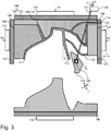
- Fig. 3 shows a subsequent method step in which the additional molded part 119 is moved away from the cast part 110 in its demolding direction r. This is done, in particular, automatically with the aid of the drive 122.
- the other molded parts 103, 105, 107 are also moved away from the cast part 110, a holding device or support for the cast part 110 being placed under the cast part between the aforementioned method steps.
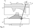
- Fig. 4 shows a later or earlier method step in which the components of the slip die 100 be put together.
- the additional molded part 119 has already been brought into a defined position relative to the first molded part 101 by means of the adjustment arrangement or the holding element 121 and the drive 122.
- the opposite second molded part 103 is placed on this arrangement by means of an adjusting force Fm.
- the third and fourth molded parts 105, 107 are then attached to the arrangement from the sides in order to completely close the slip die 100.
- a rectilinear adjustment movement along the demolding direction r can also be provided.
- any other adjustment directions r1 can be provided for the adjustment of the holding element 121 and above that of the additional molded part 119, so that it can assume any position in space if this should be desired and necessary.
- the movement sequences mentioned for assembling can also be modified, in particular also reversible.
- Fig. 4 shows a front outer wall of the first molded part sheath 102, which extends upwards in the drawing up to a mounting height of the additional molded part 119 or from its protruding molded part holding device 120.
- the first molded part sheath 102 has in its top side Wall on a recess, which serves to receive the molded part holding device 120.
Landscapes
- Engineering & Computer Science (AREA)
- Chemical & Material Sciences (AREA)
- Ceramic Engineering (AREA)
- Manufacturing & Machinery (AREA)
- Mechanical Engineering (AREA)
- Dispersion Chemistry (AREA)
- Producing Shaped Articles From Materials (AREA)
- Molds, Cores, And Manufacturing Methods Thereof (AREA)
- Casting Devices For Molds (AREA)
Priority Applications (1)
| Application Number | Priority Date | Filing Date | Title |
|---|---|---|---|
| PL13158122T PL2636498T3 (pl) | 2012-03-09 | 2013-03-07 | Forma do odlewania ciśnieniowego gęstwy lejnej, instalacja do odlewania ciśnieniowego gęstwy lejnej i sposób odlewania ciśnieniowego |
Applications Claiming Priority (1)
| Application Number | Priority Date | Filing Date | Title |
|---|---|---|---|
| DE102012004896A DE102012004896A1 (de) | 2012-03-09 | 2012-03-09 | Schlicker-Druckgießform, Schlicker-Druckgießanlage und Druckgießverfahren |
Publications (3)
| Publication Number | Publication Date |
|---|---|
| EP2636498A2 EP2636498A2 (de) | 2013-09-11 |
| EP2636498A3 EP2636498A3 (de) | 2014-06-18 |
| EP2636498B1 true EP2636498B1 (de) | 2020-07-15 |
Family
ID=47912954
Family Applications (1)
| Application Number | Title | Priority Date | Filing Date |
|---|---|---|---|
| EP13158122.5A Active EP2636498B1 (de) | 2012-03-09 | 2013-03-07 | Schlicker-Druckgießform, Schlicker-Druckgießanlage und Druckgießverfahren |
Country Status (4)
| Country | Link |
|---|---|
| EP (1) | EP2636498B1 (pl) |
| DE (1) | DE102012004896A1 (pl) |
| ES (1) | ES2819196T3 (pl) |
| PL (1) | PL2636498T3 (pl) |
Families Citing this family (4)
| Publication number | Priority date | Publication date | Assignee | Title |
|---|---|---|---|---|
| DE102015117657A1 (de) * | 2015-10-16 | 2017-04-20 | Dorst Technologies Gmbh & Co. Kg | Schlickerguss-Giessform mit einer Einspannvorrichtung, Presse und Verfahren damit |
| DE202018102563U1 (de) | 2018-05-08 | 2018-05-22 | Dorst Technologies Gmbh & Co. Kg | Schlicker-Durckgießform und Schlicker-Druckgießanlage |
| DE102020114348A1 (de) * | 2020-05-28 | 2021-12-02 | Lippert Gmbh & Co. Kg | Batteriedruckguss keramischer Hohlkörper |
| IT202400001179A1 (it) * | 2024-01-23 | 2025-07-23 | Sacmi | Sistema e metodo di colaggio per la realizzazione di articoli ceramici |
Family Cites Families (7)
| Publication number | Priority date | Publication date | Assignee | Title |
|---|---|---|---|---|
| US1776701A (en) * | 1928-05-21 | 1930-09-23 | Chicago Pottery Company | Mold for making vitreous china articles |
| FR2093348A5 (pl) * | 1970-06-11 | 1972-01-28 | Ideal Standard | |
| CH537789A (de) * | 1971-05-05 | 1973-06-15 | Laufen Keramische Ind | Giessform für keramische Gegenstände |
| JPH0383609A (ja) * | 1989-08-28 | 1991-04-09 | Toto Ltd | 泥漿鋳込み成形用分割鋳型の移動装置 |
| IT1310973B1 (it) * | 1999-09-28 | 2002-02-27 | Sacmi | Stampo di colatura perfezionato per la formatura di apparecchiigienico sanitari. |
| DE19955629A1 (de) * | 1999-11-19 | 2001-05-23 | Sama Maschb Gmbh | Vorrichtung und Verfahren zum Gießen von Sanitärartikel |
| DE102006019915A1 (de) * | 2006-04-30 | 2007-10-31 | Dorst Technologies Gmbh & Co. Kg | Gussform bzw. Gießverfahren zum Gießen eines keramischen Gussteils |
-
2012
- 2012-03-09 DE DE102012004896A patent/DE102012004896A1/de not_active Withdrawn
-
2013
- 2013-03-07 ES ES13158122T patent/ES2819196T3/es active Active
- 2013-03-07 PL PL13158122T patent/PL2636498T3/pl unknown
- 2013-03-07 EP EP13158122.5A patent/EP2636498B1/de active Active
Non-Patent Citations (1)
| Title |
|---|
| None * |
Also Published As
| Publication number | Publication date |
|---|---|
| EP2636498A2 (de) | 2013-09-11 |
| ES2819196T3 (es) | 2021-04-15 |
| EP2636498A3 (de) | 2014-06-18 |
| DE102012004896A1 (de) | 2013-09-12 |
| PL2636498T3 (pl) | 2020-12-14 |
Similar Documents
| Publication | Publication Date | Title |
|---|---|---|
| EP2899003B1 (de) | Druckgussform zur Herstellung eines Gießlings und Verfahren zur Herstellung einer einteiligen Toilette | |
| EP1345716B2 (de) | Speiser mit einem rohrähnlichen körper | |
| EP2792465B1 (de) | Säulenauszugsvorrichtung | |
| EP3003601B2 (de) | Speisereinsatz, formelement für den speisereinsatz und verfahren zum giessen von metall unter verwendung derselben | |
| EP2636498B1 (de) | Schlicker-Druckgießform, Schlicker-Druckgießanlage und Druckgießverfahren | |
| DE102016104019B3 (de) | Vorrichtung zur Herstellung von Gussteilen, wie Aluminiumguss, im Druckgießverfahren oder Niederdruckgießverfahren | |
| EP2774736B1 (de) | Pressenanordnung und Verfahren zum Pressen eines Pressteils | |
| DE10148307A1 (de) | Verfahren sowie Einrichtung zum Hohlgießen von keramischen Rohlingen, insbesondere zur Endverwertung im Sanitärbereich | |
| EP2288480B1 (de) | Form zur herstellung von betonformsteinen | |
| DE10132790B4 (de) | Druckgussanlage zum Herstellen von WC's und Herstellungsverfahren dafür | |
| DE19912829B4 (de) | Anlage zum Herstellen von napfförmigen Betonformkörpern | |
| WO2005102655A1 (de) | Vorrichtung zum herstellen von formteilen und baueinheit für eine solche vorrichtung | |
| WO2019214936A1 (de) | SCHLICKER-DRUCKGIEßFORM UND SCHLICKER-DRUCKGIEßANLAGE | |
| EP3169496A1 (de) | Pressenanordnung und verfahren zum pressen eines pressteils | |
| EP1967341A2 (de) | Form zur Herstellung von Betonformsteinen und Verfahren zur Herstellung einer Formkernanordnung einer solchen Form | |
| DE102017131280A1 (de) | Verfahren zum Herstellen eines Formteils sowie Speisereinsatz zur Verwendung in einem solchen Verfahren | |
| WO2020169462A1 (de) | EINTEILIGER SPEISERKÖRPER ZUR VERWENDUNG BEIM GIEßEN VON METALLEN | |
| DE2536142C3 (de) | Einrichtung zur Handhabung von Rotoren von Elektromotoren und zum Spritzgießen von Aluminiumkäfigwicklungen | |
| DE10242905B4 (de) | Formgusssysteme und -maschinen sowie Kernentnahmeverfahren bei Formgusssystemen und -maschinen | |
| DE102005007873B4 (de) | Vorrichtung und Verfahren zur Herstellung von mindestens ein Einlegeteil aufweisenden Druck- oder Spritzgußteilen | |
| DE10059481B4 (de) | Speiser mit einem rohrähnlichen Körper | |
| EP2694261B1 (de) | Vorrichtung zum verbinden zweier teile einer negativform zur herstellung von schachtbodenteilen aus beton | |
| DE2727257C3 (de) | Niederdruckgießmaschine | |
| DE2808644C3 (de) | Vorrichtung zum Gießen von Betonbauelementen | |
| DE3527594A1 (de) | Presse, insbesondere fuer die herstellung von keramikfliesen |
Legal Events
| Date | Code | Title | Description |
|---|---|---|---|
| PUAI | Public reference made under article 153(3) epc to a published international application that has entered the european phase |
Free format text: ORIGINAL CODE: 0009012 |
|
| AK | Designated contracting states |
Kind code of ref document: A2 Designated state(s): AL AT BE BG CH CY CZ DE DK EE ES FI FR GB GR HR HU IE IS IT LI LT LU LV MC MK MT NL NO PL PT RO RS SE SI SK SM TR |
|
| AX | Request for extension of the european patent |
Extension state: BA ME |
|
| PUAL | Search report despatched |
Free format text: ORIGINAL CODE: 0009013 |
|
| AK | Designated contracting states |
Kind code of ref document: A3 Designated state(s): AL AT BE BG CH CY CZ DE DK EE ES FI FR GB GR HR HU IE IS IT LI LT LU LV MC MK MT NL NO PL PT RO RS SE SI SK SM TR |
|
| AX | Request for extension of the european patent |
Extension state: BA ME |
|
| RIC1 | Information provided on ipc code assigned before grant |
Ipc: B28B 7/20 20060101ALI20140512BHEP Ipc: B28B 1/26 20060101AFI20140512BHEP |
|
| 17P | Request for examination filed |
Effective date: 20141211 |
|
| RBV | Designated contracting states (corrected) |
Designated state(s): AL AT BE BG CH CY CZ DE DK EE ES FI FR GB GR HR HU IE IS IT LI LT LU LV MC MK MT NL NO PL PT RO RS SE SI SK SM TR |
|
| 19U | Interruption of proceedings before grant |
Effective date: 20160204 |
|
| 19W | Proceedings resumed before grant after interruption of proceedings |
Effective date: 20160606 |
|
| STAA | Information on the status of an ep patent application or granted ep patent |
Free format text: STATUS: EXAMINATION IS IN PROGRESS |
|
| 17Q | First examination report despatched |
Effective date: 20170105 |
|
| RIN1 | Information on inventor provided before grant (corrected) |
Inventor name: HEINOLD, UWE Inventor name: TANASIJCZUK, ROMAN |
|
| TPAC | Observations filed by third parties |
Free format text: ORIGINAL CODE: EPIDOSNTIPA |
|
| GRAP | Despatch of communication of intention to grant a patent |
Free format text: ORIGINAL CODE: EPIDOSNIGR1 |
|
| STAA | Information on the status of an ep patent application or granted ep patent |
Free format text: STATUS: GRANT OF PATENT IS INTENDED |
|
| INTG | Intention to grant announced |
Effective date: 20200130 |
|
| GRAS | Grant fee paid |
Free format text: ORIGINAL CODE: EPIDOSNIGR3 |
|
| GRAA | (expected) grant |
Free format text: ORIGINAL CODE: 0009210 |
|
| STAA | Information on the status of an ep patent application or granted ep patent |
Free format text: STATUS: THE PATENT HAS BEEN GRANTED |
|
| AK | Designated contracting states |
Kind code of ref document: B1 Designated state(s): AL AT BE BG CH CY CZ DE DK EE ES FI FR GB GR HR HU IE IS IT LI LT LU LV MC MK MT NL NO PL PT RO RS SE SI SK SM TR |
|
| REG | Reference to a national code |
Ref country code: CH Ref legal event code: EP Ref country code: GB Ref legal event code: FG4D Free format text: NOT ENGLISH |
|
| REG | Reference to a national code |
Ref country code: IE Ref legal event code: FG4D Free format text: LANGUAGE OF EP DOCUMENT: GERMAN |
|
| REG | Reference to a national code |
Ref country code: DE Ref legal event code: R096 Ref document number: 502013014912 Country of ref document: DE |
|
| REG | Reference to a national code |
Ref country code: AT Ref legal event code: REF Ref document number: 1290496 Country of ref document: AT Kind code of ref document: T Effective date: 20200815 |
|
| REG | Reference to a national code |
Ref country code: LT Ref legal event code: MG4D |
|
| REG | Reference to a national code |
Ref country code: NL Ref legal event code: MP Effective date: 20200715 |
|
| PG25 | Lapsed in a contracting state [announced via postgrant information from national office to epo] |
Ref country code: PT Free format text: LAPSE BECAUSE OF FAILURE TO SUBMIT A TRANSLATION OF THE DESCRIPTION OR TO PAY THE FEE WITHIN THE PRESCRIBED TIME-LIMIT Effective date: 20201116 Ref country code: HR Free format text: LAPSE BECAUSE OF FAILURE TO SUBMIT A TRANSLATION OF THE DESCRIPTION OR TO PAY THE FEE WITHIN THE PRESCRIBED TIME-LIMIT Effective date: 20200715 Ref country code: BG Free format text: LAPSE BECAUSE OF FAILURE TO SUBMIT A TRANSLATION OF THE DESCRIPTION OR TO PAY THE FEE WITHIN THE PRESCRIBED TIME-LIMIT Effective date: 20201015 Ref country code: SE Free format text: LAPSE BECAUSE OF FAILURE TO SUBMIT A TRANSLATION OF THE DESCRIPTION OR TO PAY THE FEE WITHIN THE PRESCRIBED TIME-LIMIT Effective date: 20200715 Ref country code: LT Free format text: LAPSE BECAUSE OF FAILURE TO SUBMIT A TRANSLATION OF THE DESCRIPTION OR TO PAY THE FEE WITHIN THE PRESCRIBED TIME-LIMIT Effective date: 20200715 Ref country code: FI Free format text: LAPSE BECAUSE OF FAILURE TO SUBMIT A TRANSLATION OF THE DESCRIPTION OR TO PAY THE FEE WITHIN THE PRESCRIBED TIME-LIMIT Effective date: 20200715 Ref country code: GR Free format text: LAPSE BECAUSE OF FAILURE TO SUBMIT A TRANSLATION OF THE DESCRIPTION OR TO PAY THE FEE WITHIN THE PRESCRIBED TIME-LIMIT Effective date: 20201016 Ref country code: NO Free format text: LAPSE BECAUSE OF FAILURE TO SUBMIT A TRANSLATION OF THE DESCRIPTION OR TO PAY THE FEE WITHIN THE PRESCRIBED TIME-LIMIT Effective date: 20201015 |
|
| PG25 | Lapsed in a contracting state [announced via postgrant information from national office to epo] |
Ref country code: LV Free format text: LAPSE BECAUSE OF FAILURE TO SUBMIT A TRANSLATION OF THE DESCRIPTION OR TO PAY THE FEE WITHIN THE PRESCRIBED TIME-LIMIT Effective date: 20200715 Ref country code: RS Free format text: LAPSE BECAUSE OF FAILURE TO SUBMIT A TRANSLATION OF THE DESCRIPTION OR TO PAY THE FEE WITHIN THE PRESCRIBED TIME-LIMIT Effective date: 20200715 Ref country code: IS Free format text: LAPSE BECAUSE OF FAILURE TO SUBMIT A TRANSLATION OF THE DESCRIPTION OR TO PAY THE FEE WITHIN THE PRESCRIBED TIME-LIMIT Effective date: 20201115 |
|
| PG25 | Lapsed in a contracting state [announced via postgrant information from national office to epo] |
Ref country code: NL Free format text: LAPSE BECAUSE OF FAILURE TO SUBMIT A TRANSLATION OF THE DESCRIPTION OR TO PAY THE FEE WITHIN THE PRESCRIBED TIME-LIMIT Effective date: 20200715 |
|
| REG | Reference to a national code |
Ref country code: ES Ref legal event code: FG2A Ref document number: 2819196 Country of ref document: ES Kind code of ref document: T3 Effective date: 20210415 |
|
| REG | Reference to a national code |
Ref country code: DE Ref legal event code: R097 Ref document number: 502013014912 Country of ref document: DE |
|
| PG25 | Lapsed in a contracting state [announced via postgrant information from national office to epo] |
Ref country code: EE Free format text: LAPSE BECAUSE OF FAILURE TO SUBMIT A TRANSLATION OF THE DESCRIPTION OR TO PAY THE FEE WITHIN THE PRESCRIBED TIME-LIMIT Effective date: 20200715 Ref country code: CZ Free format text: LAPSE BECAUSE OF FAILURE TO SUBMIT A TRANSLATION OF THE DESCRIPTION OR TO PAY THE FEE WITHIN THE PRESCRIBED TIME-LIMIT Effective date: 20200715 Ref country code: DK Free format text: LAPSE BECAUSE OF FAILURE TO SUBMIT A TRANSLATION OF THE DESCRIPTION OR TO PAY THE FEE WITHIN THE PRESCRIBED TIME-LIMIT Effective date: 20200715 Ref country code: RO Free format text: LAPSE BECAUSE OF FAILURE TO SUBMIT A TRANSLATION OF THE DESCRIPTION OR TO PAY THE FEE WITHIN THE PRESCRIBED TIME-LIMIT Effective date: 20200715 Ref country code: SM Free format text: LAPSE BECAUSE OF FAILURE TO SUBMIT A TRANSLATION OF THE DESCRIPTION OR TO PAY THE FEE WITHIN THE PRESCRIBED TIME-LIMIT Effective date: 20200715 |
|
| PLBE | No opposition filed within time limit |
Free format text: ORIGINAL CODE: 0009261 |
|
| STAA | Information on the status of an ep patent application or granted ep patent |
Free format text: STATUS: NO OPPOSITION FILED WITHIN TIME LIMIT |
|
| PG25 | Lapsed in a contracting state [announced via postgrant information from national office to epo] |
Ref country code: AL Free format text: LAPSE BECAUSE OF FAILURE TO SUBMIT A TRANSLATION OF THE DESCRIPTION OR TO PAY THE FEE WITHIN THE PRESCRIBED TIME-LIMIT Effective date: 20200715 |
|
| 26N | No opposition filed |
Effective date: 20210416 |
|
| PG25 | Lapsed in a contracting state [announced via postgrant information from national office to epo] |
Ref country code: SK Free format text: LAPSE BECAUSE OF FAILURE TO SUBMIT A TRANSLATION OF THE DESCRIPTION OR TO PAY THE FEE WITHIN THE PRESCRIBED TIME-LIMIT Effective date: 20200715 |
|
| PG25 | Lapsed in a contracting state [announced via postgrant information from national office to epo] |
Ref country code: SI Free format text: LAPSE BECAUSE OF FAILURE TO SUBMIT A TRANSLATION OF THE DESCRIPTION OR TO PAY THE FEE WITHIN THE PRESCRIBED TIME-LIMIT Effective date: 20200715 |
|
| PG25 | Lapsed in a contracting state [announced via postgrant information from national office to epo] |
Ref country code: MC Free format text: LAPSE BECAUSE OF FAILURE TO SUBMIT A TRANSLATION OF THE DESCRIPTION OR TO PAY THE FEE WITHIN THE PRESCRIBED TIME-LIMIT Effective date: 20200715 |
|
| REG | Reference to a national code |
Ref country code: BE Ref legal event code: MM Effective date: 20210331 |
|
| PG25 | Lapsed in a contracting state [announced via postgrant information from national office to epo] |
Ref country code: LU Free format text: LAPSE BECAUSE OF NON-PAYMENT OF DUE FEES Effective date: 20210307 Ref country code: IE Free format text: LAPSE BECAUSE OF NON-PAYMENT OF DUE FEES Effective date: 20210307 |
|
| PGFP | Annual fee paid to national office [announced via postgrant information from national office to epo] |
Ref country code: GB Payment date: 20220322 Year of fee payment: 10 Ref country code: DE Payment date: 20220331 Year of fee payment: 10 Ref country code: CH Payment date: 20220324 Year of fee payment: 10 Ref country code: AT Payment date: 20220318 Year of fee payment: 10 |
|
| PGFP | Annual fee paid to national office [announced via postgrant information from national office to epo] |
Ref country code: TR Payment date: 20220228 Year of fee payment: 10 Ref country code: PL Payment date: 20220302 Year of fee payment: 10 Ref country code: IT Payment date: 20220323 Year of fee payment: 10 Ref country code: FR Payment date: 20220325 Year of fee payment: 10 |
|
| PG25 | Lapsed in a contracting state [announced via postgrant information from national office to epo] |
Ref country code: BE Free format text: LAPSE BECAUSE OF NON-PAYMENT OF DUE FEES Effective date: 20210331 |
|
| PGFP | Annual fee paid to national office [announced via postgrant information from national office to epo] |
Ref country code: ES Payment date: 20220414 Year of fee payment: 10 |
|
| PG25 | Lapsed in a contracting state [announced via postgrant information from national office to epo] |
Ref country code: HU Free format text: LAPSE BECAUSE OF FAILURE TO SUBMIT A TRANSLATION OF THE DESCRIPTION OR TO PAY THE FEE WITHIN THE PRESCRIBED TIME-LIMIT; INVALID AB INITIO Effective date: 20130307 |
|
| PG25 | Lapsed in a contracting state [announced via postgrant information from national office to epo] |
Ref country code: CY Free format text: LAPSE BECAUSE OF FAILURE TO SUBMIT A TRANSLATION OF THE DESCRIPTION OR TO PAY THE FEE WITHIN THE PRESCRIBED TIME-LIMIT Effective date: 20200715 |
|
| REG | Reference to a national code |
Ref country code: DE Ref legal event code: R119 Ref document number: 502013014912 Country of ref document: DE |
|
| REG | Reference to a national code |
Ref country code: CH Ref legal event code: PL |
|
| REG | Reference to a national code |
Ref country code: AT Ref legal event code: MM01 Ref document number: 1290496 Country of ref document: AT Kind code of ref document: T Effective date: 20230307 |
|
| GBPC | Gb: european patent ceased through non-payment of renewal fee |
Effective date: 20230307 |
|
| PG25 | Lapsed in a contracting state [announced via postgrant information from national office to epo] |
Ref country code: GB Free format text: LAPSE BECAUSE OF NON-PAYMENT OF DUE FEES Effective date: 20230307 |
|
| PG25 | Lapsed in a contracting state [announced via postgrant information from national office to epo] |
Ref country code: LI Free format text: LAPSE BECAUSE OF NON-PAYMENT OF DUE FEES Effective date: 20230331 Ref country code: GB Free format text: LAPSE BECAUSE OF NON-PAYMENT OF DUE FEES Effective date: 20230307 Ref country code: FR Free format text: LAPSE BECAUSE OF NON-PAYMENT OF DUE FEES Effective date: 20230331 Ref country code: DE Free format text: LAPSE BECAUSE OF NON-PAYMENT OF DUE FEES Effective date: 20231003 Ref country code: CH Free format text: LAPSE BECAUSE OF NON-PAYMENT OF DUE FEES Effective date: 20230331 Ref country code: AT Free format text: LAPSE BECAUSE OF NON-PAYMENT OF DUE FEES Effective date: 20230307 |
|
| PG25 | Lapsed in a contracting state [announced via postgrant information from national office to epo] |
Ref country code: MK Free format text: LAPSE BECAUSE OF FAILURE TO SUBMIT A TRANSLATION OF THE DESCRIPTION OR TO PAY THE FEE WITHIN THE PRESCRIBED TIME-LIMIT Effective date: 20200715 Ref country code: IT Free format text: LAPSE BECAUSE OF NON-PAYMENT OF DUE FEES Effective date: 20230307 |
|
| REG | Reference to a national code |
Ref country code: ES Ref legal event code: FD2A Effective date: 20240503 |
|
| PG25 | Lapsed in a contracting state [announced via postgrant information from national office to epo] |
Ref country code: ES Free format text: LAPSE BECAUSE OF NON-PAYMENT OF DUE FEES Effective date: 20230308 |
|
| PG25 | Lapsed in a contracting state [announced via postgrant information from national office to epo] |
Ref country code: ES Free format text: LAPSE BECAUSE OF NON-PAYMENT OF DUE FEES Effective date: 20230308 |
|
| PG25 | Lapsed in a contracting state [announced via postgrant information from national office to epo] |
Ref country code: PL Free format text: LAPSE BECAUSE OF NON-PAYMENT OF DUE FEES Effective date: 20230307 |
|
| PG25 | Lapsed in a contracting state [announced via postgrant information from national office to epo] |
Ref country code: PL Free format text: LAPSE BECAUSE OF NON-PAYMENT OF DUE FEES Effective date: 20230307 |
|
| PG25 | Lapsed in a contracting state [announced via postgrant information from national office to epo] |
Ref country code: MT Free format text: LAPSE BECAUSE OF FAILURE TO SUBMIT A TRANSLATION OF THE DESCRIPTION OR TO PAY THE FEE WITHIN THE PRESCRIBED TIME-LIMIT Effective date: 20200715 |