EP2634331B1 - Automatikschloss - Google Patents
Automatikschloss Download PDFInfo
- Publication number
- EP2634331B1 EP2634331B1 EP13155216.8A EP13155216A EP2634331B1 EP 2634331 B1 EP2634331 B1 EP 2634331B1 EP 13155216 A EP13155216 A EP 13155216A EP 2634331 B1 EP2634331 B1 EP 2634331B1
- Authority
- EP
- European Patent Office
- Prior art keywords
- control cam
- probe
- movement
- automatic lock
- button
- Prior art date
- Legal status (The legal status is an assumption and is not a legal conclusion. Google has not performed a legal analysis and makes no representation as to the accuracy of the status listed.)
- Active
Links
Images

Classifications
-
- E—FIXED CONSTRUCTIONS
- E05—LOCKS; KEYS; WINDOW OR DOOR FITTINGS; SAFES
- E05B—LOCKS; ACCESSORIES THEREFOR; HANDCUFFS
- E05B63/00—Locks or fastenings with special structural characteristics
- E05B63/18—Locks or fastenings with special structural characteristics with arrangements independent of the locking mechanism for retaining the bolt or latch in the retracted position
- E05B63/20—Locks or fastenings with special structural characteristics with arrangements independent of the locking mechanism for retaining the bolt or latch in the retracted position released automatically when the wing is closed
-
- E—FIXED CONSTRUCTIONS
- E05—LOCKS; KEYS; WINDOW OR DOOR FITTINGS; SAFES
- E05B—LOCKS; ACCESSORIES THEREFOR; HANDCUFFS
- E05B17/00—Accessories in connection with locks
- E05B17/22—Means for operating or controlling lock or fastening device accessories, i.e. other than the fastening members, e.g. switches, indicators
-
- E—FIXED CONSTRUCTIONS
- E05—LOCKS; KEYS; WINDOW OR DOOR FITTINGS; SAFES
- E05B—LOCKS; ACCESSORIES THEREFOR; HANDCUFFS
- E05B47/00—Operating or controlling locks or other fastening devices by electric or magnetic means
- E05B47/0038—Operating or controlling locks or other fastening devices by electric or magnetic means using permanent magnets
-
- E—FIXED CONSTRUCTIONS
- E05—LOCKS; KEYS; WINDOW OR DOOR FITTINGS; SAFES
- E05B—LOCKS; ACCESSORIES THEREFOR; HANDCUFFS
- E05B63/00—Locks or fastenings with special structural characteristics
- E05B63/0065—Operating modes; Transformable to different operating modes
-
- E—FIXED CONSTRUCTIONS
- E05—LOCKS; KEYS; WINDOW OR DOOR FITTINGS; SAFES
- E05C—BOLTS OR FASTENING DEVICES FOR WINGS, SPECIALLY FOR DOORS OR WINDOWS
- E05C9/00—Arrangements of simultaneously actuated bolts or other securing devices at well-separated positions on the same wing
- E05C9/18—Details of fastening means or of fixed retaining means for the ends of bars
- E05C9/1825—Fastening means
- E05C9/1875—Fastening means performing pivoting movements
-
- E—FIXED CONSTRUCTIONS
- E05—LOCKS; KEYS; WINDOW OR DOOR FITTINGS; SAFES
- E05C—BOLTS OR FASTENING DEVICES FOR WINGS, SPECIALLY FOR DOORS OR WINDOWS
- E05C9/00—Arrangements of simultaneously actuated bolts or other securing devices at well-separated positions on the same wing
- E05C9/18—Details of fastening means or of fixed retaining means for the ends of bars
- E05C9/1808—Keepers
Definitions
- the invention relates to an automatic lock with a lock case and a locking plate to be arranged opposite lock plate, with an open position located in a lock case in a protruding from the lock case locking position movable latch and with a button for detecting the position of a locking plate connected to the control cam, said Button in the position in which the lock case is opposite the strike plate, spaced from the strike plate, and with a trigger actuated by the button to release the movement of the bolt from the open position to the closed position, wherein the control cam between one in the range of movement of the button located release position and a withdrawn, located outside the range of movement of the probe basic position is movable and can be fixed in the basic position.
- Such automatic locks allow a self-locking when a door equipped with it is closed.
- the automatic locks are fixed, for example, with the lock case, the bolt and the button in a wing of a door and the strike plate in a frame.
- the button When mounted, the button is depressed when the sash is closed and releases the movement of the bolt.
- the button When known from practice locks the button slides over when closing the door the striking plate and thus creates annoying sanding marks.
- the EP 1 158 126 B1 discloses a lock in which the control cam is adjustable and disposed opposite the button in the strike plate. By actuating the button via the control cam, it is possible to prevent the button from dragging over the striking plate and generating grinding marks. However, the position of the control cam must be adjusted consuming. If the control cam is too far away from the strike plate, this can in the worst case lead to the control cam abutting the lock case.
- Another disadvantage of the known automatic lock is that the button gets against the control cam each time it closes. Thus, the automatic lock is activated at any time.
- the invention is based on the problem of further developing an automatic lock of the type mentioned above so that an automatic function can be easily activated or deactivated.
- control cam is rotatably mounted in a sleeve and is fixed axially displaceable in a rotational position and in the other rotational position in the basic position.
- the automatic function can be activated or deactivated.
- the control cam In the basic position, the control cam is permanently outside the range of movement of the button. Thus, the actuation of the button is prevented in this basic position, so that the bolt is not extended in this case. By loosening the fixation the control cam can be easily moved to the release position and activate the automatic function of the automatic lock according to the invention.
- the fixation of the control cam in the basic position is particularly convenient if a displaceable transversely to the direction of the control cam control bar in a first position creates a positive connection with the cam located in the basic position and releases the movement of the control cam in a second position.
- the control bar for the positive connection with the control cam has an edge which penetrates into the basic position in a groove of the control cam.
- an eccentric can be designed to control a plurality of control cam.
- the structural complexity for guiding the control cam can be kept particularly low according to another advantageous embodiment of the invention, when the control cam is axially displaceably guided in a sleeve.
- control cam is only moved into the release position when the lock case is above the strike plate.
- the control cam and push button come together so that the button can perform the intended function in the automatic lock. Since the control cam is only moved in the position in which it controls the button, the control cam does not need to be adjusted. A touch of the button on the strike plate is reliably avoided thanks to the invention. Therefore, no grinding marks are created by the movement of the probe. Furthermore, disturbing, protruding from the strike plate components are avoided with the wing open.
- the control cam is guided in a one-piece manufactured with a closing edge for the bolt component, because in this way the triggering position of the probe is set very precisely.
- control of the movement of the control cam is particularly simple according to an advantageous embodiment of the invention, when the magnet is arranged in at least one of the components button or control cam.
- the magnet can be easily retrofitted to existing locks according to another advantageous embodiment of the invention, when the magnet is arranged on the lock case.
- a cover rail covering the faceplate can be designed magnetically.
- the movement of the magnet can be reliably ensured according to another advantageous embodiment of the invention, when the control cam is held by a spring element in the retracted position.
- the triggering of the pushbutton is particularly easy, according to another advantageous development of the invention, if at least one of the control cam or pushbutton components has a run-up ramp projecting into the movement region of the other component.
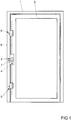
- the espagnolette lock 3 has a main lock 4 and a plurality of secondary locks formed as automatic locks 5.
- the main lock 4 is connected via a drive rod 6 with the automatic locks 5 and has a
- the drive device 7 may be a generally known handle, a lock cylinder and / or a motor drive.
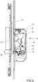
- FIG. 2 shows one of the automatic locks 5 in an unlocked position with a lock case shown open 8.
- a latch 9 is pivoted back completely in this unlocked position in the lock case 8 and is supported via an arm 10 on a biased by a torsion spring 11 button 12 from.
- a fixed in the lock case 8 spring element 13 biases the bolt 9 with the arm 10 against the button 12 in front. If the button 12 is depressed, this comes out of the range of movement of the arm 10 of the bolt 9 and releases the movement of the bolt 9 out of the lock case 8.
- the drive rod 6 is coupled to a slide 14 guided in the lock case 8.
- the lock case 8 is arranged in the wing 2 and is opposite to a fixed in the frame 1 strike plate 15.
- a arranged in the strike plate 15 control cam 16 is in a lowered basic position. In this basic position, the control cam 16 is not able to actuate the button 12.
- An automatic function, in which the bolt 9 is extended by the force of the spring element 13, is in the in FIG. 2 shown disabled position by the position of the control cam 16 in the normal position.
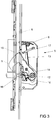
- the control cam 16 can be moved into a protruding release position in which he presses the button 12. This position is in FIG. 3 shown.
- the button 12 By pressing the button 12 via the control cam 16, the movement of the arm 10 of the bolt 9 and thus the bolt 9 is released itself.
- the bolt 9 snaps by the force of the spring element 13 from the lock case 8 out into the strike plate 15.
- the automatic lock 5 is thus in the locked position.
- the latch 9 is also engaged behind by a pivotable pawl 17.
- the slider 14 is used to drive the bolt 9 of the in FIG. 3 illustrated locked position in an unlocked position.
- the pawl 17 is pivoted and at the same time the latch 9 is pushed back into the lock case 8.
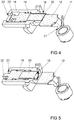
- FIG. 4 shows the button 12 and the control cam 16 in an enlarged perspective view.
- the control cam 16 is slidably disposed in a sleeve 18 connected to the closing plate 15 and biased by a spring element 19 in a position located in the range of movement of the probe 12 position and has on its side facing the button 12 a magnet 20.
- the magnet 20 acts with the made of steel lock case 8 together, so that when closing the in FIG. 1 shown door of the magnet 20 against the force of the spring element 19 from the retracted position in the in FIG. 3 shown triggering position is pulled.
- the button 12 has an angle 21 for supporting the arm 10 of the bolt 9. The angle 21 and the arm 10 thus form a trigger for selectively blocking or releasing the movement of the bolt. 9
- FIG. 5 shows the button 12 and the control cam 16 FIG. 4 when in basic position fixed control cam 16.
- the control cam 16 is rotatably disposed in the sleeve 18 and has at its end facing away from the button 12 a cross bar 22 which engages behind an elongated recess 23 in the bottom of the sleeve 18.
- the sleeve 18 is shown in section. Starting from the position FIG. 4 can the control cam 16 push with a suitable tool in the sleeve 18 and from the in FIG. 4 shown rotational position in the in FIG. 5 move shown rotational position.
- the control cam 16 is fixed in the sleeve 18 and an actuation of the button 12 when closing the door is omitted. This deactivates the automatic function of the automatic lock.
- FIG. 6 shows a further embodiment of a control cam 24 and a button 25. These differ from those FIGS. 4 and 5 especially in that the control cam 24 has a ramp 26, with which he presses the button 25 when closing the door.
- the control cam 24 is itself designed magnetically and can be moved from a arranged on the lock case 8 and schematically shown here magnets 27 from a located in a sleeve 28 basic position in the illustrated release position.
- FIG. 6 is the control cam 24 with a cross bar 29 in a guide 30 of the sleeve 28. Pressed starting from the position FIG. 6 the control cam 24 into the sleeve 28, the crossbar 29 passes out of the guide 30 of the sleeve 28 out. Subsequently, the control cam 24 of the in FIG. 6 shown rotational position in the in FIG. 7 pivot position shown pivot, so that the cross bar 29 is fixed outside of the guide 30. This deactivates the automatic function of the automatic lock.
- control cam 16, 24 may also be arranged on the strike plate 15, a slider which is disposed in a position outside the range of movement of the control cam 16, 24 and can be pushed into a second position on the sleeve 18, 28.
- the control cam 16, 24 would also be fixed in a located in the sleeve 18, 28 basic position.
Landscapes
- Engineering & Computer Science (AREA)
- Structural Engineering (AREA)
- Mechanical Engineering (AREA)
- Lock And Its Accessories (AREA)
- Casings For Electric Apparatus (AREA)
- Closures For Containers (AREA)
Priority Applications (1)
| Application Number | Priority Date | Filing Date | Title |
|---|---|---|---|
| PL13155216T PL2634331T3 (pl) | 2012-02-28 | 2013-02-14 | Zamek automatyczny |
Applications Claiming Priority (1)
| Application Number | Priority Date | Filing Date | Title |
|---|---|---|---|
| DE102012203054A DE102012203054A1 (de) | 2012-02-28 | 2012-02-28 | Automatikschloss |
Publications (3)
| Publication Number | Publication Date |
|---|---|
| EP2634331A2 EP2634331A2 (de) | 2013-09-04 |
| EP2634331A3 EP2634331A3 (de) | 2017-06-21 |
| EP2634331B1 true EP2634331B1 (de) | 2019-05-29 |
Family
ID=47683648
Family Applications (1)
| Application Number | Title | Priority Date | Filing Date |
|---|---|---|---|
| EP13155216.8A Active EP2634331B1 (de) | 2012-02-28 | 2013-02-14 | Automatikschloss |
Country Status (3)
| Country | Link |
|---|---|
| EP (1) | EP2634331B1 (pl) |
| DE (1) | DE102012203054A1 (pl) |
| PL (1) | PL2634331T3 (pl) |
Families Citing this family (1)
| Publication number | Priority date | Publication date | Assignee | Title |
|---|---|---|---|---|
| DE102017105125A1 (de) * | 2017-03-10 | 2018-09-13 | Carl Fuhr Gmbh & Co. Kg | Verriegelungseinheit für eine Schließanlage einer Tür |
Family Cites Families (3)
| Publication number | Priority date | Publication date | Assignee | Title |
|---|---|---|---|---|
| GB2286627B (en) * | 1993-12-28 | 1997-04-16 | Total Prod Sales Ltd | Door latch lock |
| DE29916887U1 (de) | 1999-09-25 | 2001-02-08 | Karl Fliether Gmbh & Co, 42551 Velbert | Schloß |
| DE202009014455U1 (de) * | 2009-10-26 | 2010-02-11 | Kfv Karl Fliether Gmbh & Co. Kg | Treibstangensperre |
-
2012
- 2012-02-28 DE DE102012203054A patent/DE102012203054A1/de not_active Withdrawn
-
2013
- 2013-02-14 PL PL13155216T patent/PL2634331T3/pl unknown
- 2013-02-14 EP EP13155216.8A patent/EP2634331B1/de active Active
Non-Patent Citations (1)
| Title |
|---|
| None * |
Also Published As
| Publication number | Publication date |
|---|---|
| DE102012203054A1 (de) | 2013-08-29 |
| EP2634331A2 (de) | 2013-09-04 |
| PL2634331T3 (pl) | 2019-12-31 |
| EP2634331A3 (de) | 2017-06-21 |
Similar Documents
| Publication | Publication Date | Title |
|---|---|---|
| EP2179116B1 (de) | Türschloss | |
| DE202008004173U1 (de) | Verriegelungsvorrichtung | |
| EP2673434B1 (de) | Schloss mit einer falle und einer zusatzfalle zur ablaufsicherung einer riegelbewegung | |
| EP2634330B1 (de) | Automatikschloss | |
| EP2666938B1 (de) | Schloss für eine tür | |
| EP3034728B1 (de) | Öffnungsbegrenzereinrichtung | |
| EP2634331B1 (de) | Automatikschloss | |
| EP3426867B1 (de) | Schloss | |
| DE102015000606A1 (de) | Verriegelungsvorrichtung für einen schwenkbar gelagerten Flügel | |
| EP3091151A1 (de) | Treibstangensperre für einen treibstangenbeschlag | |
| EP1739257B1 (de) | Schloss | |
| DE102013103898A1 (de) | Zuhaltevorrichtung für Schiebetüren und Verschlussvorrichtung für Schiebetüren | |
| EP2634333A2 (de) | Schloss | |
| EP3498942B1 (de) | Schloss | |
| EP3208407A1 (de) | Schloss mit einer sicherheitsvorrichtung | |
| DE202014009557U1 (de) | Schloss,insbesondere Glastürschloss | |
| EP3029233B1 (de) | Treibstangenschloss | |
| EP2615229A2 (de) | Schließanlage | |
| EP3498943B1 (de) | Schloss | |
| EP2690237B1 (de) | Automatikschloss | |
| EP2696014B1 (de) | Automatikschloss | |
| EP2808468A2 (de) | Verriegelungseinheit für eine Schließanlage | |
| EP2738324A2 (de) | Schloss mit einer freigebbaren Dreheinheit | |
| EP2696013B1 (de) | Automatikschloss | |
| EP1514986A2 (de) | Treibstangenschloss |
Legal Events
| Date | Code | Title | Description |
|---|---|---|---|
| PUAI | Public reference made under article 153(3) epc to a published international application that has entered the european phase |
Free format text: ORIGINAL CODE: 0009012 |
|
| AK | Designated contracting states |
Kind code of ref document: A2 Designated state(s): AL AT BE BG CH CY CZ DE DK EE ES FI FR GB GR HR HU IE IS IT LI LT LU LV MC MK MT NL NO PL PT RO RS SE SI SK SM TR |
|
| AX | Request for extension of the european patent |
Extension state: BA ME |
|
| PUAL | Search report despatched |
Free format text: ORIGINAL CODE: 0009013 |
|
| AK | Designated contracting states |
Kind code of ref document: A3 Designated state(s): AL AT BE BG CH CY CZ DE DK EE ES FI FR GB GR HR HU IE IS IT LI LT LU LV MC MK MT NL NO PL PT RO RS SE SI SK SM TR |
|
| AX | Request for extension of the european patent |
Extension state: BA ME |
|
| RIC1 | Information provided on ipc code assigned before grant |
Ipc: E05B 63/20 20060101AFI20170517BHEP Ipc: E05C 9/18 20060101ALN20170517BHEP Ipc: E05B 47/00 20060101ALI20170517BHEP |
|
| STAA | Information on the status of an ep patent application or granted ep patent |
Free format text: STATUS: REQUEST FOR EXAMINATION WAS MADE |
|
| 17P | Request for examination filed |
Effective date: 20171121 |
|
| RBV | Designated contracting states (corrected) |
Designated state(s): AL AT BE BG CH CY CZ DE DK EE ES FI FR GB GR HR HU IE IS IT LI LT LU LV MC MK MT NL NO PL PT RO RS SE SI SK SM TR |
|
| STAA | Information on the status of an ep patent application or granted ep patent |
Free format text: STATUS: EXAMINATION IS IN PROGRESS |
|
| 17Q | First examination report despatched |
Effective date: 20180517 |
|
| GRAP | Despatch of communication of intention to grant a patent |
Free format text: ORIGINAL CODE: EPIDOSNIGR1 |
|
| STAA | Information on the status of an ep patent application or granted ep patent |
Free format text: STATUS: GRANT OF PATENT IS INTENDED |
|
| RIC1 | Information provided on ipc code assigned before grant |
Ipc: E05C 9/18 20060101ALN20181212BHEP Ipc: E05B 47/00 20060101ALI20181212BHEP Ipc: E05B 17/22 20060101ALI20181212BHEP Ipc: E05B 63/20 20060101AFI20181212BHEP |
|
| INTG | Intention to grant announced |
Effective date: 20190111 |
|
| GRAS | Grant fee paid |
Free format text: ORIGINAL CODE: EPIDOSNIGR3 |
|
| GRAA | (expected) grant |
Free format text: ORIGINAL CODE: 0009210 |
|
| STAA | Information on the status of an ep patent application or granted ep patent |
Free format text: STATUS: THE PATENT HAS BEEN GRANTED |
|
| AK | Designated contracting states |
Kind code of ref document: B1 Designated state(s): AL AT BE BG CH CY CZ DE DK EE ES FI FR GB GR HR HU IE IS IT LI LT LU LV MC MK MT NL NO PL PT RO RS SE SI SK SM TR |
|
| REG | Reference to a national code |
Ref country code: GB Ref legal event code: FG4D Free format text: NOT ENGLISH |
|
| REG | Reference to a national code |
Ref country code: CH Ref legal event code: EP |
|
| REG | Reference to a national code |
Ref country code: AT Ref legal event code: REF Ref document number: 1138353 Country of ref document: AT Kind code of ref document: T Effective date: 20190615 |
|
| REG | Reference to a national code |
Ref country code: DE Ref legal event code: R096 Ref document number: 502013012903 Country of ref document: DE |
|
| REG | Reference to a national code |
Ref country code: IE Ref legal event code: FG4D Free format text: LANGUAGE OF EP DOCUMENT: GERMAN |
|
| REG | Reference to a national code |
Ref country code: NL Ref legal event code: FP |
|
| REG | Reference to a national code |
Ref country code: LT Ref legal event code: MG4D |
|
| PG25 | Lapsed in a contracting state [announced via postgrant information from national office to epo] |
Ref country code: FI Free format text: LAPSE BECAUSE OF FAILURE TO SUBMIT A TRANSLATION OF THE DESCRIPTION OR TO PAY THE FEE WITHIN THE PRESCRIBED TIME-LIMIT Effective date: 20190529 Ref country code: LT Free format text: LAPSE BECAUSE OF FAILURE TO SUBMIT A TRANSLATION OF THE DESCRIPTION OR TO PAY THE FEE WITHIN THE PRESCRIBED TIME-LIMIT Effective date: 20190529 Ref country code: AL Free format text: LAPSE BECAUSE OF FAILURE TO SUBMIT A TRANSLATION OF THE DESCRIPTION OR TO PAY THE FEE WITHIN THE PRESCRIBED TIME-LIMIT Effective date: 20190529 Ref country code: ES Free format text: LAPSE BECAUSE OF FAILURE TO SUBMIT A TRANSLATION OF THE DESCRIPTION OR TO PAY THE FEE WITHIN THE PRESCRIBED TIME-LIMIT Effective date: 20190529 Ref country code: PT Free format text: LAPSE BECAUSE OF FAILURE TO SUBMIT A TRANSLATION OF THE DESCRIPTION OR TO PAY THE FEE WITHIN THE PRESCRIBED TIME-LIMIT Effective date: 20190930 Ref country code: SE Free format text: LAPSE BECAUSE OF FAILURE TO SUBMIT A TRANSLATION OF THE DESCRIPTION OR TO PAY THE FEE WITHIN THE PRESCRIBED TIME-LIMIT Effective date: 20190529 Ref country code: HR Free format text: LAPSE BECAUSE OF FAILURE TO SUBMIT A TRANSLATION OF THE DESCRIPTION OR TO PAY THE FEE WITHIN THE PRESCRIBED TIME-LIMIT Effective date: 20190529 Ref country code: NO Free format text: LAPSE BECAUSE OF FAILURE TO SUBMIT A TRANSLATION OF THE DESCRIPTION OR TO PAY THE FEE WITHIN THE PRESCRIBED TIME-LIMIT Effective date: 20190829 |
|
| PG25 | Lapsed in a contracting state [announced via postgrant information from national office to epo] |
Ref country code: LV Free format text: LAPSE BECAUSE OF FAILURE TO SUBMIT A TRANSLATION OF THE DESCRIPTION OR TO PAY THE FEE WITHIN THE PRESCRIBED TIME-LIMIT Effective date: 20190529 Ref country code: GR Free format text: LAPSE BECAUSE OF FAILURE TO SUBMIT A TRANSLATION OF THE DESCRIPTION OR TO PAY THE FEE WITHIN THE PRESCRIBED TIME-LIMIT Effective date: 20190830 Ref country code: BG Free format text: LAPSE BECAUSE OF FAILURE TO SUBMIT A TRANSLATION OF THE DESCRIPTION OR TO PAY THE FEE WITHIN THE PRESCRIBED TIME-LIMIT Effective date: 20190829 Ref country code: RS Free format text: LAPSE BECAUSE OF FAILURE TO SUBMIT A TRANSLATION OF THE DESCRIPTION OR TO PAY THE FEE WITHIN THE PRESCRIBED TIME-LIMIT Effective date: 20190529 |
|
| PG25 | Lapsed in a contracting state [announced via postgrant information from national office to epo] |
Ref country code: EE Free format text: LAPSE BECAUSE OF FAILURE TO SUBMIT A TRANSLATION OF THE DESCRIPTION OR TO PAY THE FEE WITHIN THE PRESCRIBED TIME-LIMIT Effective date: 20190529 Ref country code: RO Free format text: LAPSE BECAUSE OF FAILURE TO SUBMIT A TRANSLATION OF THE DESCRIPTION OR TO PAY THE FEE WITHIN THE PRESCRIBED TIME-LIMIT Effective date: 20190529 Ref country code: CZ Free format text: LAPSE BECAUSE OF FAILURE TO SUBMIT A TRANSLATION OF THE DESCRIPTION OR TO PAY THE FEE WITHIN THE PRESCRIBED TIME-LIMIT Effective date: 20190529 Ref country code: DK Free format text: LAPSE BECAUSE OF FAILURE TO SUBMIT A TRANSLATION OF THE DESCRIPTION OR TO PAY THE FEE WITHIN THE PRESCRIBED TIME-LIMIT Effective date: 20190529 Ref country code: SK Free format text: LAPSE BECAUSE OF FAILURE TO SUBMIT A TRANSLATION OF THE DESCRIPTION OR TO PAY THE FEE WITHIN THE PRESCRIBED TIME-LIMIT Effective date: 20190529 |
|
| PG25 | Lapsed in a contracting state [announced via postgrant information from national office to epo] |
Ref country code: SM Free format text: LAPSE BECAUSE OF FAILURE TO SUBMIT A TRANSLATION OF THE DESCRIPTION OR TO PAY THE FEE WITHIN THE PRESCRIBED TIME-LIMIT Effective date: 20190529 Ref country code: IT Free format text: LAPSE BECAUSE OF FAILURE TO SUBMIT A TRANSLATION OF THE DESCRIPTION OR TO PAY THE FEE WITHIN THE PRESCRIBED TIME-LIMIT Effective date: 20190529 |
|
| REG | Reference to a national code |
Ref country code: DE Ref legal event code: R097 Ref document number: 502013012903 Country of ref document: DE |
|
| PG25 | Lapsed in a contracting state [announced via postgrant information from national office to epo] |
Ref country code: TR Free format text: LAPSE BECAUSE OF FAILURE TO SUBMIT A TRANSLATION OF THE DESCRIPTION OR TO PAY THE FEE WITHIN THE PRESCRIBED TIME-LIMIT Effective date: 20190529 |
|
| PLBE | No opposition filed within time limit |
Free format text: ORIGINAL CODE: 0009261 |
|
| STAA | Information on the status of an ep patent application or granted ep patent |
Free format text: STATUS: NO OPPOSITION FILED WITHIN TIME LIMIT |
|
| 26N | No opposition filed |
Effective date: 20200303 |
|
| PG25 | Lapsed in a contracting state [announced via postgrant information from national office to epo] |
Ref country code: SI Free format text: LAPSE BECAUSE OF FAILURE TO SUBMIT A TRANSLATION OF THE DESCRIPTION OR TO PAY THE FEE WITHIN THE PRESCRIBED TIME-LIMIT Effective date: 20190529 |
|
| REG | Reference to a national code |
Ref country code: CH Ref legal event code: PL |
|
| REG | Reference to a national code |
Ref country code: BE Ref legal event code: MM Effective date: 20200229 |
|
| PG25 | Lapsed in a contracting state [announced via postgrant information from national office to epo] |
Ref country code: LU Free format text: LAPSE BECAUSE OF NON-PAYMENT OF DUE FEES Effective date: 20200214 Ref country code: MC Free format text: LAPSE BECAUSE OF FAILURE TO SUBMIT A TRANSLATION OF THE DESCRIPTION OR TO PAY THE FEE WITHIN THE PRESCRIBED TIME-LIMIT Effective date: 20190529 |
|
| PG25 | Lapsed in a contracting state [announced via postgrant information from national office to epo] |
Ref country code: LI Free format text: LAPSE BECAUSE OF NON-PAYMENT OF DUE FEES Effective date: 20200229 Ref country code: CH Free format text: LAPSE BECAUSE OF NON-PAYMENT OF DUE FEES Effective date: 20200229 |
|
| PG25 | Lapsed in a contracting state [announced via postgrant information from national office to epo] |
Ref country code: IE Free format text: LAPSE BECAUSE OF NON-PAYMENT OF DUE FEES Effective date: 20200214 |
|
| PG25 | Lapsed in a contracting state [announced via postgrant information from national office to epo] |
Ref country code: BE Free format text: LAPSE BECAUSE OF NON-PAYMENT OF DUE FEES Effective date: 20200229 |
|
| PG25 | Lapsed in a contracting state [announced via postgrant information from national office to epo] |
Ref country code: MT Free format text: LAPSE BECAUSE OF FAILURE TO SUBMIT A TRANSLATION OF THE DESCRIPTION OR TO PAY THE FEE WITHIN THE PRESCRIBED TIME-LIMIT Effective date: 20190529 Ref country code: CY Free format text: LAPSE BECAUSE OF FAILURE TO SUBMIT A TRANSLATION OF THE DESCRIPTION OR TO PAY THE FEE WITHIN THE PRESCRIBED TIME-LIMIT Effective date: 20190529 |
|
| PGFP | Annual fee paid to national office [announced via postgrant information from national office to epo] |
Ref country code: PL Payment date: 20220202 Year of fee payment: 10 |
|
| PG25 | Lapsed in a contracting state [announced via postgrant information from national office to epo] |
Ref country code: MK Free format text: LAPSE BECAUSE OF FAILURE TO SUBMIT A TRANSLATION OF THE DESCRIPTION OR TO PAY THE FEE WITHIN THE PRESCRIBED TIME-LIMIT Effective date: 20190529 Ref country code: IS Free format text: LAPSE BECAUSE OF FAILURE TO SUBMIT A TRANSLATION OF THE DESCRIPTION OR TO PAY THE FEE WITHIN THE PRESCRIBED TIME-LIMIT Effective date: 20190929 |
|
| PGFP | Annual fee paid to national office [announced via postgrant information from national office to epo] |
Ref country code: NL Payment date: 20230220 Year of fee payment: 11 |
|
| P01 | Opt-out of the competence of the unified patent court (upc) registered |
Effective date: 20230512 |
|
| PG25 | Lapsed in a contracting state [announced via postgrant information from national office to epo] |
Ref country code: PL Free format text: LAPSE BECAUSE OF NON-PAYMENT OF DUE FEES Effective date: 20230214 |
|
| PG25 | Lapsed in a contracting state [announced via postgrant information from national office to epo] |
Ref country code: PL Free format text: LAPSE BECAUSE OF NON-PAYMENT OF DUE FEES Effective date: 20230214 |
|
| REG | Reference to a national code |
Ref country code: NL Ref legal event code: MM Effective date: 20240301 |
|
| REG | Reference to a national code |
Ref country code: DE Ref legal event code: R081 Ref document number: 502013012903 Country of ref document: DE Owner name: AUG. WINKHAUS SE & CO. KG, DE Free format text: FORMER OWNER: AUG. WINKHAUS GMBH & CO. KG, 48291 TELGTE, DE Ref country code: DE Ref legal event code: R081 Ref document number: 502013012903 Country of ref document: DE Owner name: AUG. WINKHAUS SE, DE Free format text: FORMER OWNER: AUG. WINKHAUS GMBH & CO. KG, 48291 TELGTE, DE |
|
| PG25 | Lapsed in a contracting state [announced via postgrant information from national office to epo] |
Ref country code: NL Free format text: LAPSE BECAUSE OF NON-PAYMENT OF DUE FEES Effective date: 20240301 |
|
| PG25 | Lapsed in a contracting state [announced via postgrant information from national office to epo] |
Ref country code: NL Free format text: LAPSE BECAUSE OF NON-PAYMENT OF DUE FEES Effective date: 20240301 |
|
| PGFP | Annual fee paid to national office [announced via postgrant information from national office to epo] |
Ref country code: DE Payment date: 20250218 Year of fee payment: 13 |
|
| PGFP | Annual fee paid to national office [announced via postgrant information from national office to epo] |
Ref country code: AT Payment date: 20250217 Year of fee payment: 13 |
|
| PGFP | Annual fee paid to national office [announced via postgrant information from national office to epo] |
Ref country code: FR Payment date: 20250219 Year of fee payment: 13 |
|
| PGFP | Annual fee paid to national office [announced via postgrant information from national office to epo] |
Ref country code: GB Payment date: 20250220 Year of fee payment: 13 |
|
| REG | Reference to a national code |
Ref country code: DE Ref legal event code: R081 Ref document number: 502013012903 Country of ref document: DE Owner name: AUG. WINKHAUS SE, DE Free format text: FORMER OWNER: AUG. WINKHAUS SE & CO. KG, 48291 TELGTE, DE |