EP2633372B1 - Procédé de fonctionnement d'une installation domotique - Google Patents
Procédé de fonctionnement d'une installation domotique Download PDFInfo
- Publication number
- EP2633372B1 EP2633372B1 EP11773292.5A EP11773292A EP2633372B1 EP 2633372 B1 EP2633372 B1 EP 2633372B1 EP 11773292 A EP11773292 A EP 11773292A EP 2633372 B1 EP2633372 B1 EP 2633372B1
- Authority
- EP
- European Patent Office
- Prior art keywords
- control unit
- mobile control
- equipment
- home
- operating method
- Prior art date
- Legal status (The legal status is an assumption and is not a legal conclusion. Google has not performed a legal analysis and makes no representation as to the accuracy of the status listed.)
- Active
Links
Images

Classifications
-
- G—PHYSICS
- G05—CONTROLLING; REGULATING
- G05B—CONTROL OR REGULATING SYSTEMS IN GENERAL; FUNCTIONAL ELEMENTS OF SUCH SYSTEMS; MONITORING OR TESTING ARRANGEMENTS FOR SUCH SYSTEMS OR ELEMENTS
- G05B15/00—Systems controlled by a computer
- G05B15/02—Systems controlled by a computer electric
-
- H—ELECTRICITY
- H04—ELECTRIC COMMUNICATION TECHNIQUE
- H04L—TRANSMISSION OF DIGITAL INFORMATION, e.g. TELEGRAPHIC COMMUNICATION
- H04L12/00—Data switching networks
- H04L12/28—Data switching networks characterised by path configuration, e.g. LAN [Local Area Networks] or WAN [Wide Area Networks]
- H04L12/2803—Home automation networks
- H04L12/2807—Exchanging configuration information on appliance services in a home automation network
- H04L12/2809—Exchanging configuration information on appliance services in a home automation network indicating that an appliance service is present in a home automation network
-
- G—PHYSICS
- G05—CONTROLLING; REGULATING
- G05B—CONTROL OR REGULATING SYSTEMS IN GENERAL; FUNCTIONAL ELEMENTS OF SUCH SYSTEMS; MONITORING OR TESTING ARRANGEMENTS FOR SUCH SYSTEMS OR ELEMENTS
- G05B2219/00—Program-control systems
- G05B2219/20—Pc systems
- G05B2219/26—Pc applications
- G05B2219/2642—Domotique, domestic, home control, automation, smart house
Definitions
- the invention relates to the field of controlling home automation equipment in a building or its surroundings, such as motorized closing or solar protection equipment, heating and air conditioning, lighting, and individual swimming pool management.
- These home automation devices communicate with each other using a home automation network of the radiofrequency or power line type, and can communicate with remote servers.
- the patent application WO 03/007266 describes the control of an object from a distance using a pointer equipped with a light source.
- the patent application WO 03/088486 describes a near-field evaluation method making it possible to ensure, during the transmission of a pairing command, that a transmitter of this command is located in the immediate vicinity of a receiver.
- patent application WO 03/081352 describes a process for changing the common key while the patent US 7,683,754 describes a method of selecting a group for the transmission of a common key, for example by using the supply voltage of only the elements of the group.
- the patent application WO 2010/049383 describes a portable unit capable of communicating without contact in the near field with electronic labels placed on home automation equipment and / or in particular places in a building, for example at the entrance to rooms in a dwelling.
- Patent applications EP 0 973 126 and EP 1 164 540 describe the use of the SIM code of a memory card of a mobile telephone, and possibly of a fingerprint reader of this mobile telephone, to secure the control of equipment. The same goes for the patent US 6,535,107 which concerns the field of the identification of a vehicle driver. In this case, a transponder is inserted into the mobile phone in order to allow data exchange with the vehicle's security system.
- the transmitter intended to establish communication with the element to be controlled is connected to the mobile phone through the headphone jack or pairing and uses DTMF modulation or the like to transmit the encoded signals from the mobile phone to the transmitter.
- the patent EP 0 913 979 also describes the addition to a mobile phone of an additional transmitter for the remote control of an object.
- a specific mode allows remote control without using mobile radio communication and the SIM subscriber code of the card is used as a means of authenticating the user.
- the cellular structure of the mobile communication network is used as an authentication control possibility.
- the patent application US 2002/0031228 describes a mobile telephone capable of communicating both with a public communication network of GSM type and, at a short distance, with Bluetooth devices, for example hotel room locks or rental vehicle locks.
- a connection between the mobile phone and a remote server is provided via the GSM network.
- the remote server transmits the Bluetooth authentication key to the mobile phone, in an encrypted form that can be decrypted by the mobile phone.
- the Bluetooth authentication key is then transmitted by the mobile phone to the Bluetooth device by means of the Bluetooth transmitter.
- the user's personal identification code PIN can be used to secure the transmission.
- the patent application DE 10 2005038 471 similarly describes a mobile terminal communicating both over the GSM network and over Bluetooth or the like, to allow access to rental vehicles.
- the user identifies himself with a password on the mobile terminal.
- WO 00/57375 describes an anti-theft security system for household electrical equipment. Whenever the equipment is powered on, it will only function upon receipt of a release code, transmitted by a home controller through the power supply or a local network. Any equipment moved from its authorized position, that is to say not receiving its release code from the house controller, ceases to function. It is expected that the house controller itself can be stolen together with the household electrical equipment.
- the house controller includes a location means, for example by means of a cellular network or by GPS, and it can transmit its position to a remote operational center, for example by using the Internet or GSM network.
- the house controller has no other function in an installation than to ensure the blocking or unblocking of equipment in the event of its disconnection and reconnection to the electrical network.
- the patent application WO 01/71685 describes a universal remote control and methods capable of displaying on the screen of the remote control icons relating to the equipment within radio range of the remote control, and / or the control interfaces of this equipment.
- the patent application FR 2 924 890 describes a method for automatically selecting a peripheral such as home automation equipment using a proximity criterion: a message is broadcast to all the peripherals and each of them responds. Depending on the signal level received, the nearest peripheral is automatically located to send it a command.
- the patent US 7,289,014 describes an access barrier control system such as a gate or garage door, in particular as a function of the position and / or direction of movement of a vehicle in the vicinity of the access barrier. It is provided ( figure 9 ) that particular positions of a transponder or "proximity device" can be learned using a GPS satellite tracking system, so that the control system causes a predetermined action when the "proximity device »Finds such a position, after learning. For example, if the proximity device is in a so-called action position, then an action on a button causes an opening command, which is not the case outside this action position.
- the patent US 6,563,430 describes a remote control device whose control user interface depends on the position of the control device. Numerous methods of determining the position are described. Position information is not used to locate particular equipment.
- the patent US 7,363,028 also describes this type of control device and in particular a method of radiofrequency identification of the equipment closest to the control device, by progressive decrease in the transmission power. There is no use of position information from the control device to identify a particular piece of equipment. On the contrary, the position of the control device can be deduced from that of a particular item of equipment, in order to be able to place itself in a functional configuration linked to this position.
- the patent US 7,110,761 describes the use of a pointing device to establish a wireless connection between the pointing device and another device, targeted by the pointing device, in order to acquire contextual information on the device to be controlled.
- the pointing device uses the direction of electric, magnetic or electromagnetic waves.
- the patent US 7,516,039 describes a device for mapping a room comprising several rooms, using an inertial sensor. This device is intended in particular for military applications in urban combat.
- the document US2006 / 0074494 describes a system and a method for locating home automation equipment in a building.
- the distance information between a transmitter and a receiver can be used to define a transmission power just sufficient to send a message.
- the aim of the invention is to provide a method of operating an installation which overcomes the drawbacks mentioned above and improves the methods known from the prior art.
- the invention proposes a secure operating method in which it is possible to locate, in a simple and user-friendly manner, using a mobile control unit, such as a mobile telephone, various equipment items of the installation both for controlling them and for geographically insert them into the installation.
- the position information can be expressed in a spatial mesh capable of differentiating the respective positions of two pieces of equipment of the home automation installation.
- the particular item of equipment may be the item of equipment closest to the mobile control unit during the step of locating the mobile control unit.
- the method can comprise a step of aiming at the particular equipment, using a sighting means of the mobile control unit, capable of providing sighting information and in that the position information comprises sighting information.
- the sighting information can include orientation information of the mobile control unit during the sighting step and / or information on the distance between the mobile control unit and the particular equipment item, in particular telemetry information issued. of the sighting means of the mobile control unit.
- the method may comprise, following the identification step, a step of transmitting to the mobile control unit an identifier of the particular equipment item and / or of transmission to the particular equipment item of a selection instruction.
- the position information can be transmitted over the home automation network to all the devices or at least to a specific device.
- the position information can be transmitted to a remote server using a means of communication of the GSM type and / or a shared network of the Internet type.
- the location step can use equipment location data, located in a cartographic memory.
- the method may include a step of displaying, on a display means of the mobile control unit, a control interface of the particular equipment item.
- the method may include a control step in which the mobile control unit sends a control message over the home automation network to the particular equipment item, this control message comprising the identifier of the particular home automation equipment or having been preceded by a selection message comprising the identifier of the particular home automation equipment and the method may include a step of executing the command by the particular equipment.
- the method comprises a configuration step in which the position of the particular equipment item, determined during the tracking step from the location of the mobile control unit, is recorded in a cartographic memory.
- the data from the cartographic memory can be transferred to a three-dimensional model of the building.
- a home automation installation comprising equipment and a mobile control unit
- the equipment and the mobile control unit comprise hardware and software means for implementing the operating method defined above.
- the mobile control unit comprises hardware and software means for implementing the operating method defined above.
- the invention also relates to a computer program comprising a computer program code means suitable for carrying out the steps of the method defined above, when the program is executed on a computer.
- the operating method applies both to a mode of use and to a configuration mode.
- position information relating to the mobile control unit is used to locate a particular item of equipment: either because the position of this item of equipment is already known and that it is, by locating the equipment, to select it so that it can execute a command, either because it is a newly installed equipment and it is a question, by locating this equipment, of determining its position in order to be able to record this during the configuration step.
- the same mobile control unit can be used to configure an installation or can be used to control equipment, the same training applies to the installer and the user, the same reflexes are acquired. This results in a significant gain both in economic terms and in training or information.
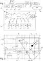
- the figure 1 represents in the form of a functional diagram a home automation installation 100 and a mobile control unit 40 according to the invention.
- the figure also represents the connections of the home automation installation and of the mobile control unit with the environment.
- the installation can include a much higher number of control units and / or sensors and can include other equipment in addition to or replacement of the equipment listed above, in particular equipment of the patio awning actuator type, of water treatment, ventilation, etc., including domestic type such as a washing machine, a TV etc.
- the invention however preferably applies to equipment occupying a fixed place in the building.
- All the devices communicate with each other on the same home automation network 20, of local type (LAN) and using a common protocol, for example io-homecontrol, EIB, Zigbee, etc. (registered trademarks).
- the home automation network is of the radiofrequency type, which is represented by bidirectional arrows and an antenna symbol on each device.
- several local networks of different protocol and / or media are used to form the home automation network 20.
- the devices therefore each comprise a means of network connection to the home automation network 20.
- the devices are all of the active type, that is to say say that they are able to send or receive a control command, or even a measurement datum coming from a sensor of the equipment.
- HK house key All the equipment shares a common key, known as the HK house key.
- This key is for example a 64 or 128 bit word, housed in a memory of each device and an authentication algorithm using the common key is used to allow a device to recognize that a command order or any message is from other equipment in the installation.
- this authentication is carried out by a dialogue between the sender of the message and its recipient, or is carried out by an encryption of the content of the message using the common key, or else requires both a dialogue and an encryption. the content of the message.
- the eighth device 18 can be connected to a shared network 30 of the Internet type by a gateway, not shown.
- a remote server 31 can also be connected to the shared network, thus making communication possible between the eighth device and the remote server.
- a mobile control unit 40 comprises network link means to the home automation network 20, this network link means also being represented by the symbol of an antenna and a double arrow. This connection means allows communication between the mobile control unit and any equipment in the home automation network.
- the mobile control unit comprises locating means 41 making it possible to determine the position of the mobile control unit. It can also be connected to the server 31 by a long-distance communication network 32, for example of the communication network type for GSM portable telephones.
- the location means 41 preferably uses an external resource 33, for example GPS or Galileo type geolocation satellites providing signals.
- the mobile control unit can also be provided with a sighting means 42.
- the sighting means comprises a telemetry means 44 capable of providing information on the distance between the mobile control unit and an object. target aimed by the sighting means.
- the sighting means comprises for example a photographic lens of variable focal length with autofocus device, as described in figure 9 .
- the sighting means may comprise a means 43 for measuring the orientation of the mobile control unit, in particular an inclination means, comprising for example an accelerometer, in particular a 3D accelerometer or any device of the compass or compass type.
- the locating means may also include an accelerometer for establishing part of a location information.
- an accelerometer for establishing part of a location information.
- the same 3D accelerometer is used in the localization means, for displacement measurements with respect to a reference point and in the orientation measurement means for orientation measurements of the mobile control unit.
- a portable telephone equipped with the hardware means described above and with software means capable of executing the methods described below can advantageously serve as a mobile control unit.
- the network connection means to the home automation network is for example housed in the SIM card of the telephone, or in the battery of the telephone, or it is linked to the telephone by a removable connection, such as a jack.
- the network connection means is detailed under the reference 45 on the figure 9 : it includes, in permanent memory 46, the PTL protocol of the home automation network and it includes, in erasable memory 47, the common key HK, if this has been transmitted by means of a network link.
- the network connection means functionally linked to the mobile control unit, is however materially distinct from the telephone and can only be supplied, for example, by a manufacturer of one of the equipment items of the home automation network.
- This distinctive character of the network connection means appears in the form of a bold line.
- the mobile control unit becomes an element of the installation 100 as soon as it communicates with one of the items of equipment, which membership is symbolized by a dotted arrow A0.
- this belonging of the mobile control unit to the installation can only be temporary, in particular in the case where the mobile control unit is used as a configuration tool by an installer.
- the figure 2 spatially represents a building comprising the home automation installation and the mobile control unit, according to a spatial grid in plan represented by two perpendicular networks of equidistant lines in dotted lines, the intersections of which are nodes of the grid, identified by two coordinates (X , Y).
- the spatial mesh advantageously comprises a third dimension (Z), and each node is identified by three coordinates (X, Y, Z).
- the spatial mesh is able to differentiate the respective positions of two items of equipment of the home automation installation, that is to say that these two items of equipment have different sets of coordinates.
- Each device is shown centered on the closest node. The distance between two consecutive lines of the grid (the pitch of the grid) is therefore less than or equal to the minimum distance separating two devices.
- the spatial grid must therefore be sufficiently precise, not only to be able to distinguish the current equipment from the installation but also to allow the future installation of new equipment.
- a much finer spatial mesh than that represented can be used, but then offering an excess of precision compared to the need.
- the spatial mesh can be for example twice as precise, or even 10 times more precise, than that shown, with a view to the possible installation of other equipment in intermediate positions.
- a mesh pitch of 10 cm corresponds to a preferred value.
- the figure 2 for which the mesh is substantially metric, is therefore not representative of a real mesh.
- the mesh has a self-adaptive pitch, the pitch of the grid being for example defined by progressively passing from a coarse grid to a finer grid depending on the existence or not of a plurality of responses to an interrogation message, this message being emitted with an increasingly low power as described in the patent US 7,363,028 .
- the installation is distributed in a main body of house 101 and in a garage 102 adjoining the main body. Partitions internal to the building are not shown. Bays relating to the garage door, the main door and the windows fitted with roller shutters are shown as a triple line.
- the mobile control unit 40 is placed in the installation, its position being identified by coordinates X1 and Y1 in the spatial mesh.
- An arrow A1 indicates a direction aimed by the sighting means of the mobile control unit.
- a particular position P0 is identified by coordinates X0 and Y0. Its role will be described below.
- the installation comprises hardware and / or software means making it possible to govern its operation in accordance with the method which is the subject of the invention.
- the software means can in particular comprise a computer program code means suitable for carrying out the steps of the method according to the invention, when the program is running on a computer.
- the installation comprises means for locating the mobile control unit, the locating means being included at least partially in the mobile control unit and delivering position information.
- the installation also comprises a locating means using at least the position information to locate specific equipment.
- the installation also comprises a means making it possible to identify the particular equipment in a mode of use of the home automation installation and making it possible to locate the particular equipment in a configuration mode of the home automation installation.
- the control unit comprises hardware and / or software means making it possible to govern its operation in accordance with the method which is the subject of the invention.
- the software means can in particular comprise a computer program code means suitable for carrying out the steps of the method according to the invention, when the program is running on a computer.
- the mobile control unit can be used in a secure manner to control the equipment of the installation, in particular with the aim of spatially locating an equipment item with respect to the mobile control unit or vice versa.
- position information from the mobile control unit is used.
- This position information can in particular be defined by a spatial mesh capable of differentiating the respective positions of two items of equipment of the home automation installation.
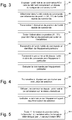
- a first step S1 the mobile control unit is placed in the building equipped with the home automation installation of the equipment located in the building and / or around the building.
- a second step S2 is activated, in which information on the position of the mobile unit control is determined in the mobile control unit, using its locating means. If the mobile control unit is in the position of the figure 2 , the position information is for example the pair of coordinates X1, Y1.
- the position information can be deduced from GPS geolocation data, corrected so as to obtain a sufficiently precise mesh but without excessive precision.
- a mesh pitch of 10 cm is for example preferred. If the GPS precision is too great, for example centimeter, then the last coordinate digit is not taken into account in the position information. If the GPS precision is too low, for example metric, then the displacements measured by the accelerometer of the mobile control unit are taken into account in order to obtain a more precise location, corresponding to the desired grid. GPS accuracy can also be improved by analyzing the radio power received from the equipment.
- the precision of the mesh can be adapted dynamically, depending on the gradual addition of new equipment in the installation.
- the displacements can be measured from a reference position, for example the particular position P0.
- any position information can be simply deduced from the movements of the mobile control unit from the reference position.
- a third step S3 the position information of the mobile control unit is broadcast by the latter to the equipment of the home automation network.
- This step assumes that the house key has already been supplied to the mobile control unit, during a step prior to the implementation of the operating method. For example, the house key was transmitted in encrypted form to the mobile control unit by the remote server and the GSM communication network.
- a fourth step S4 the position information is processed by at least one specific item of equipment of the installation, for example the eighth item of equipment in order to locate a particular item of equipment of the installation.
- a location criterion uses the position information of the mobile control unit: for example, the particular equipment item is the equipment closest to the mobile control unit at the time when the second step was activated. Other criteria can be used to identify particular equipment.
- the specific equipment comprises a first cartographic memory 51 in which have been stored (during a configuration step which will be described in relation to the figure 7 ) the position coordinates of each item of equipment in the installation.
- the mobile control unit transmits a command to the particular equipment item.
- the order includes the identifier of the particular equipment and an order to be executed.
- the latter results from an action by the user on a control interface of the mobile control unit.
- it may be a prerecorded order, for example a change of state order.
- it may be an order resulting from a particular movement of the control unit, for example a pivoting of the latter around an axis.
- a seventh step S7 the particular equipment item receives and executes the command.
- the position information relating to the mobile control unit is used to locate a particular item of equipment: either because the position of this item of equipment is already known and that is, by locating the equipment during the processing step, to select it so that it executes a command, either because it is a new item of equipment and that it is, by locating the equipment during the processing step , to determine its position in order to be able to record it during a configuration step.
- a first variant of the embodiment of the operating method according to the invention is described below with reference to figure 4 .
- This first variant differs from the embodiment described above in that the last three steps S5-S7 are respectively replaced by three substitution steps S5'-S7 '.
- a selection instruction is transmitted to the particular equipment item by the specific equipment item.
- the selection instruction advantageously comprises the identifier of the mobile control unit. It means that the particular equipment will have to execute any next command broadcast by the mobile control unit on the home automation network. Alternatively, the particular device will have to execute a command marked as specific and broadcast by the mobile control unit on the home automation network.
- a sixth substitution step S6 ′ the mobile control unit broadcasts a command over the home automation network. Unlike a point-to-point type transmission, the broadcast does not specify a particular recipient.
- a seventh substitution step S7 ′ the command is received by all the devices but is executed only by the particular device (or all the particular devices), having previously received the selection instruction.
- a second variant of the embodiment of the operating method according to the invention is described below with reference to figure 5 .
- This second variant differs from the embodiment described above as regards the place of processing of the fourth step.
- this processing step can be executed in the remote server, the latter also possibly containing a second cartographic memory 52 containing the coordinates of the equipment of the installation.
- the third step S3 can consist in sending the position information directly to the remote server, using the GSM communication network.
- the fifth step can consist in also using the GSM network to transmit the identifier of the particular equipment item to the mobile control unit.
- the information can always be transmitted to or received from the specific equipment, the latter communicating them to the remote server via the Internet network.
- a third variant of the embodiment of the operating method according to the invention is described below with reference to figure 6 .
- This third variant differs from the embodiment described above in that it comprises sub-steps in addition to the operating method.
- the particular manipulation comprises an action of aiming of the particular equipment item with the aiming means of the mobile control unit.
- a second sub-step S21 an orientation information item of the mobile control unit RCU is determined in the mobile control unit RCU using the orientation measuring means.
- a third sub-step S22 telemetry information on the distance between the mobile control unit RCU and the particular equipment item is also determined, using the telemetry means.
- the orientation information and the telemetry information are combined to constitute sighting information. Alternatively, the sighting information only includes the orientation information if there is no telemetry means.
- a fifth sub-step S31 completing the third step, the sighting information is transmitted in addition to the position information of the mobile control unit.
- a sixth sub-step S42 completing the fourth step, the position information and the sighting information are used simultaneously to identify the particular equipment item.
- the different steps of the method can be iterated for the same particular item of equipment, as long as the precision does not make it possible to identify a single particular item of equipment: for example because two items of equipment are currently located at the same distance from the mobile control unit.
- An audio or visual feedback signal for example in the form of an icon on the screen of the mobile control unit, may indicate that no particular item of equipment is identifiable, or conversely that a particular item of equipment is identified.
- the first three variants of the mode of execution of the method have been described in a mode of use of the installation.
- a fourth variant of the embodiment of the operating method according to the invention is described below with reference to figure 7 .
- This fourth variant is used in a configuration mode, when the mobile control unit is used, for example by an installer, to configure the installation by establishing in particular a map of its various items of equipment. In this case, the coordinates of the equipment are not yet recorded in a cartographic memory.
- identifier of the particular equipment item by a known means, for example by photographing a bar code of a label of the equipment, or even by reading an electronic label of the equipment, comprising its identifier, or by sending an order to the equipment by means of a local command, this order being picked up by the mobile control unit in order to deduce the identifier therefrom, and possibly other information relating to the equipment.
- a seventh sub-step S43 in which the positional coordinates of the equipment, deduced from the position information and possibly from the sighting information, makes it possible to record in the cartographic memory these coordinates, in relation to the 'identifier of the particular equipment.
- the equipment identifier is transmitted to a transponder on the unit mobile control by an electronic tag of the equipment and the position of the mobile control unit, therefore of the equipment, is determined, both being stored in a cartographic memory.
- a third cartographic memory 53 may be placed on the mobile control unit, to record these data and subsequently communicate them as a whole to the remote server or to the specific equipment item.
- the mobile control unit communicates directly with each new item of equipment as soon as it has been identified, to transmit the house key HK to it or simply to ensure its operation.
- the mobile control unit and / or the remote server and / or the specific equipment comprises software for three-dimensional modeling of a building, able to use the data from the cartographic memory to establish and / or complete a three-dimensional modeling. of the building, including the position of the equipment.
- the virtual reconstruction of a building including the equipment of the installation can thus be carried out, in particular by combining the invention with the teachings of the patent. US 7,516,039 .
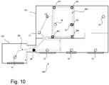
- the figure 10 describes two cases of implementation of the control method when it is used in a configuration mode within the installation home automation 100 previous.
- the internal partitions of the building are this time visible.
- the installer provided with the mobile control unit moves directly from one device to another, as shown diagrammatically by a first path W1, and he only takes action on the mobile control unit when locating each item of equipment, for example items 17 and 11. Only the position of the items of equipment is recorded and they are therefore all marked: either relatively, one by one relative to the others and / or relative to the initial position, or in an absolute manner if the localization means allow it.
- the installation plan is then completed in a schematic manner by the installer, using assisted drawing tools making it possible to establish a more or less faithful sketch but greatly helped by the references that are the equipment.
- the installer has to move along the walls and partitions, and takes action on the mobile control unit not only when locating an item of equipment but also when each change of route and / or particular break (passage of a door for example), as shown diagrammatically by a second route W2.
- the installer schematically records the changes of route R1, R2, R4 and the passage of door R5, in addition to the marking R3 of the equipment 15. And the same for all the parts, for all the levels and for all the equipment in each room.
- the second path is recorded by the mobile control unit (or by the remote server), which makes it possible to reconstitute all the walls and passages of the building in addition to the location of the equipment.
- the plan of the installation as generated automatically by the mobile control unit (or by the remote server) then shows the equipment, walls, partitions and openings of the building and can be refined by using drawing software. 2D or 3D assisted.
- the reference position can be a position known only to the owner or the only installer of the installation. This position therefore serves as an identification code and certain functions, for example the transfer of the house key, can only be carried out if the mobile control unit is placed in the reference position or in a reduced zone including the position. reference.
- Another variant (not shown) of the mode of execution of the operating method according to the invention differs from the mode of execution described above in that steps S3 and S5 are omitted.
- the step S4 of processing the position information and the identification of the particular equipment item is then carried out at the level of the mobile control unit.
- the invention makes it possible to use the same operating method and the same mobile control unit to identify a particular item of equipment in order to control it in a mode of use and in order to determine its position in a configuration mode.
- the identification is therefore of the selective type in the first case, leading to the identification of an identifier, and of the spatial type in the second case, leading to the identification of a position.
- Spatial type markings are established in relative positions, for example with respect to the reference position, or in absolute positions, for example in a GPS coordinate system.
- the embodiment and its various variants described above can be combined with each other, just as the variants can be combined with each other: for example, the sighting means described in the mode of use can advantageously be used in the mode. configuration.
Landscapes
- Engineering & Computer Science (AREA)
- Automation & Control Theory (AREA)
- Physics & Mathematics (AREA)
- General Physics & Mathematics (AREA)
- General Engineering & Computer Science (AREA)
- Computer Networks & Wireless Communication (AREA)
- Signal Processing (AREA)
- Selective Calling Equipment (AREA)
- Telephonic Communication Services (AREA)
- Mobile Radio Communication Systems (AREA)
Priority Applications (1)
| Application Number | Priority Date | Filing Date | Title |
|---|---|---|---|
| PL11773292T PL2633372T3 (pl) | 2010-10-26 | 2011-10-25 | Sposób działania instalacji automatyki domowej |
Applications Claiming Priority (2)
| Application Number | Priority Date | Filing Date | Title |
|---|---|---|---|
| FR1058764A FR2966625B1 (fr) | 2010-10-26 | 2010-10-26 | Procede de fonctionnement d'une installation domotique. |
| PCT/EP2011/068632 WO2012055856A1 (fr) | 2010-10-26 | 2011-10-25 | Procédé de fonctionnement d'une installation domotique |
Publications (2)
| Publication Number | Publication Date |
|---|---|
| EP2633372A1 EP2633372A1 (fr) | 2013-09-04 |
| EP2633372B1 true EP2633372B1 (fr) | 2021-12-22 |
Family
ID=44260375
Family Applications (1)
| Application Number | Title | Priority Date | Filing Date |
|---|---|---|---|
| EP11773292.5A Active EP2633372B1 (fr) | 2010-10-26 | 2011-10-25 | Procédé de fonctionnement d'une installation domotique |
Country Status (6)
| Country | Link |
|---|---|
| US (1) | US10416622B2 (pl) |
| EP (1) | EP2633372B1 (pl) |
| CN (1) | CN103261981B (pl) |
| FR (1) | FR2966625B1 (pl) |
| PL (1) | PL2633372T3 (pl) |
| WO (1) | WO2012055856A1 (pl) |
Families Citing this family (31)
| Publication number | Priority date | Publication date | Assignee | Title |
|---|---|---|---|---|
| US10678225B2 (en) | 2013-03-04 | 2020-06-09 | Fisher-Rosemount Systems, Inc. | Data analytic services for distributed industrial performance monitoring |
| US10909137B2 (en) | 2014-10-06 | 2021-02-02 | Fisher-Rosemount Systems, Inc. | Streaming data for analytics in process control systems |
| US9558220B2 (en) | 2013-03-04 | 2017-01-31 | Fisher-Rosemount Systems, Inc. | Big data in process control systems |
| US9804588B2 (en) | 2014-03-14 | 2017-10-31 | Fisher-Rosemount Systems, Inc. | Determining associations and alignments of process elements and measurements in a process |
| US10866952B2 (en) | 2013-03-04 | 2020-12-15 | Fisher-Rosemount Systems, Inc. | Source-independent queries in distributed industrial system |
| US9397836B2 (en) | 2014-08-11 | 2016-07-19 | Fisher-Rosemount Systems, Inc. | Securing devices to process control systems |
| US9665088B2 (en) | 2014-01-31 | 2017-05-30 | Fisher-Rosemount Systems, Inc. | Managing big data in process control systems |
| US10223327B2 (en) | 2013-03-14 | 2019-03-05 | Fisher-Rosemount Systems, Inc. | Collecting and delivering data to a big data machine in a process control system |
| US10649424B2 (en) | 2013-03-04 | 2020-05-12 | Fisher-Rosemount Systems, Inc. | Distributed industrial performance monitoring and analytics |
| US10282676B2 (en) | 2014-10-06 | 2019-05-07 | Fisher-Rosemount Systems, Inc. | Automatic signal processing-based learning in a process plant |
| US10386827B2 (en) | 2013-03-04 | 2019-08-20 | Fisher-Rosemount Systems, Inc. | Distributed industrial performance monitoring and analytics platform |
| US9823626B2 (en) | 2014-10-06 | 2017-11-21 | Fisher-Rosemount Systems, Inc. | Regional big data in process control systems |
| US10649449B2 (en) | 2013-03-04 | 2020-05-12 | Fisher-Rosemount Systems, Inc. | Distributed industrial performance monitoring and analytics |
| US10649413B2 (en) | 2013-03-15 | 2020-05-12 | Fisher-Rosemount Systems, Inc. | Method for initiating or resuming a mobile control session in a process plant |
| GB2513957B (en) * | 2013-03-15 | 2020-11-25 | Fisher Rosemount Systems Inc | Method and apparatus for determining the position of a mobile control device in a process plant |
| US10296668B2 (en) | 2013-03-15 | 2019-05-21 | Fisher-Rosemount Systems, Inc. | Data modeling studio |
| WO2015048811A2 (en) * | 2013-09-30 | 2015-04-02 | Schneider Electric Industries Sas | Cloud-authenticated site resource management devices, apparatuses, methods and systems |
| US20150160935A1 (en) * | 2013-12-06 | 2015-06-11 | Vivint, Inc. | Managing device configuration information |
| WO2015095170A1 (en) | 2013-12-19 | 2015-06-25 | Electrolux Home Products, Inc. | System, method, apparatus, and computer program product for configuring a network connected appliance to use online services |
| FR3024783B1 (fr) * | 2014-08-11 | 2017-07-21 | Somfy Sas | Configuration securisee d'une installation domotique |
| WO2016034236A1 (de) * | 2014-09-04 | 2016-03-10 | Aizo Group Ag | Verfahren zur datenerhebung für die konfiguration eines gebäudeautomationssystems und verfahren zum konfigurieren eines gebäudeautomationssystems |
| US10168691B2 (en) | 2014-10-06 | 2019-01-01 | Fisher-Rosemount Systems, Inc. | Data pipeline for process control system analytics |
| US9536421B2 (en) | 2015-06-02 | 2017-01-03 | Qualcomm Technologies International, Ltd. | Intuitive way to point, access and control appliances and other objects in building interiors |
| US10503483B2 (en) | 2016-02-12 | 2019-12-10 | Fisher-Rosemount Systems, Inc. | Rule builder in a process control network |
| CN105911872A (zh) * | 2016-05-17 | 2016-08-31 | 安徽泰然信息技术工程有限公司 | 一种家庭智能生活管理系统 |
| CN106874612A (zh) * | 2017-02-27 | 2017-06-20 | 山东建筑大学 | 一种面向用户定制的住区模型生成设计方法 |
| US10887125B2 (en) * | 2017-09-15 | 2021-01-05 | Kohler Co. | Bathroom speaker |
| EP3871428B1 (en) | 2018-10-26 | 2024-12-18 | Carrier Corporation | System for monitoring smart utilities |
| CN110691116B (zh) * | 2019-08-18 | 2023-04-14 | 朗德万斯公司 | 用于管理网络设备的方法、定位设备及系统 |
| CN112434981A (zh) * | 2020-12-17 | 2021-03-02 | 上海智大电子有限公司 | 一种综合管廊人物自动跟随的管控方法、系统以及存储介质 |
| FR3147674B1 (fr) * | 2023-04-04 | 2025-11-07 | Somfy Activites Sa | Procédé de configuration d’une installation domotique. |
Family Cites Families (43)
| Publication number | Priority date | Publication date | Assignee | Title |
|---|---|---|---|---|
| EP0869462A1 (en) * | 1997-02-17 | 1998-10-07 | BRITISH TELECOMMUNICATIONS public limited company | Security systems |
| EP0973126A1 (en) | 1997-10-27 | 2000-01-19 | LOUREIRO BENIMELI, Fermin, Jaime | System for the multiple communication of data from information carrying cards provided with a microprocessor and memory or the like |
| DE19748054A1 (de) | 1997-10-30 | 1999-05-12 | Bosch Gmbh Robert | Verfahren zum Betrieb eines Mobiltelefons und Mobiltelefon |
| US6563430B1 (en) * | 1998-12-11 | 2003-05-13 | Koninklijke Philips Electronics N.V. | Remote control device with location dependent interface |
| DE19852223A1 (de) | 1998-11-12 | 2000-05-18 | Bayerische Motoren Werke Ag | Identifizierungseinrichtung für den Benutzer eines Fahrzeugs |
| CA2367094A1 (en) | 1999-03-19 | 2000-09-28 | British Telecommunications Public Limited Company | Security systems |
| EP1164540A1 (en) | 1999-05-12 | 2001-12-19 | LOUREIRO BENIMELI, Fermin, Jaime | Multiple data intercommunication system with information carrying cards fitted with a microprocessor and memory or the like and security system thereof |
| US6791467B1 (en) | 2000-03-23 | 2004-09-14 | Flextronics Semiconductor, Inc. | Adaptive remote controller |
| GB2364202A (en) | 2000-06-27 | 2002-01-16 | Nokia Mobile Phones Ltd | Mobile phone for opening locks |
| US7301946B2 (en) | 2000-11-22 | 2007-11-27 | Cisco Technology, Inc. | System and method for grouping multiple VLANs into a single 802.11 IP multicast domain |
| US7116977B1 (en) * | 2000-12-19 | 2006-10-03 | Bellsouth Intellectual Property Corporation | System and method for using location information to execute an action |
| FI114949B (fi) | 2001-03-28 | 2005-01-31 | Valtion Teknillinen | Menetelmä elektronisen laitteen ohjaamiseksi ja elektroninen järjestelmä |
| FR2827415B1 (fr) | 2001-07-12 | 2003-12-12 | Somfy | Dispositif de commande a distance de dispositif electrique |
| FR2835997B1 (fr) | 2002-02-11 | 2004-11-26 | Somfy | Procede de definition d'un groupe parmi des objets bidirectionnels |
| US20030174049A1 (en) * | 2002-03-18 | 2003-09-18 | Precision Dynamics Corporation | Wearable identification appliance that communicates with a wireless communications network such as bluetooth |
| FR2837939B1 (fr) | 2002-03-26 | 2004-09-17 | Somfy | Procede de reprogrammation d'objets bidirectionnels |
| FR2838523B1 (fr) | 2002-04-16 | 2006-06-23 | Siminor Technologies Castres S | Procede d'interpretation d'un ordre radio-electronique en fonction de sa zone d'emission |
| JP2004201098A (ja) * | 2002-12-19 | 2004-07-15 | Matsushita Electric Ind Co Ltd | 電子機器およびワイヤレスリモコン装置 |
| JP3906801B2 (ja) * | 2002-12-27 | 2007-04-18 | 松下電工株式会社 | 集合住宅用ホームオートメーションシステム |
| CN1521998A (zh) * | 2003-02-09 | 2004-08-18 | 业盛科技股份有限公司 | 家庭网路保安系统 |
| EP1482718A1 (en) | 2003-05-27 | 2004-12-01 | Siu Ling Ko | Remote control system for electrical apparatus |
| CN1286001C (zh) * | 2003-09-29 | 2006-11-22 | 天津市中环系统工程有限责任公司 | 智能家居控制系统 |
| US7363028B2 (en) * | 2003-11-04 | 2008-04-22 | Universal Electronics, Inc. | System and method for controlling device location determination |
| US7136709B2 (en) * | 2003-11-04 | 2006-11-14 | Universal Electronics Inc. | Home appliance control system and methods in a networked environment |
| US7155305B2 (en) * | 2003-11-04 | 2006-12-26 | Universal Electronics Inc. | System and methods for home appliance identification and control in a networked environment |
| US7289014B2 (en) | 2003-12-23 | 2007-10-30 | Wayne-Dalton Corp. | System for automatically moving access barriers and methods for using the same |
| FR2869134B1 (fr) * | 2004-04-16 | 2008-10-03 | Somfy Soc Par Actions Simplifiee | Procede de transmission d'informations entre objets bidirectionnels |
| JP2006033795A (ja) * | 2004-06-15 | 2006-02-02 | Sanyo Electric Co Ltd | リモートコントロールシステム、コントローラ、コンピュータにコントローラの機能を付与するプログラム、当該プログラムを格納した記憶媒体、およびサーバ。 |
| US7382271B2 (en) * | 2004-09-29 | 2008-06-03 | Siemens Building Technologies, Inc. | Automated position detection for wireless building automation devices |
| DE102005038471A1 (de) | 2005-08-13 | 2007-02-15 | Daimlerchrysler Ag | Verfahren und Vorrichtung zur Sicherung von Fahrzeugen vor unbefugter Nutzung |
| JP4451378B2 (ja) * | 2005-11-08 | 2010-04-14 | 株式会社日立製作所 | 機器設定情報通知方法及び機器 |
| US7302359B2 (en) | 2006-02-08 | 2007-11-27 | Honeywell International Inc. | Mapping systems and methods |
| FR2898719A1 (fr) | 2006-07-07 | 2007-09-21 | France Telecom | Procede de parametrisation d'une interface de commande adaptable,et systeme d'adaptation associe. |
| US7864043B2 (en) * | 2007-03-28 | 2011-01-04 | Sony Ericsson Mobile Communications Ab | Home locating network |
| US7843333B2 (en) * | 2007-01-26 | 2010-11-30 | Sony Ericsson Mobile Communication Ab | System, methods, devices and computer program products for controlling electronic appliances within a local area |
| US8738907B2 (en) | 2007-08-02 | 2014-05-27 | Motorola Solutiions, Inc. | Wireless device authentication and security key management |
| US8175590B2 (en) | 2007-09-26 | 2012-05-08 | Stryker Corporation | System for preventing unintended activation of a medical device by a portable remote control console |
| DE102007059246A1 (de) | 2007-12-07 | 2009-07-23 | Novoferm Tormatic Gmbh | Betriebseinheit für den automatischen Betrieb eines Torantriebes oder dergleichen und Verfahren für eine solche Betriebseinheit |
| US8255090B2 (en) * | 2008-02-01 | 2012-08-28 | Energyhub | System and method for home energy monitor and control |
| FR2924890A1 (fr) | 2008-04-04 | 2009-06-12 | Emmanuel Rouyer | Procede de selection automatique de peripherique par critere de proximite |
| JP2010035055A (ja) * | 2008-07-30 | 2010-02-12 | Panasonic Corp | 遠隔操作装置、ネット家電、遠隔操作システム、および遠隔操作方法 |
| WO2010018538A1 (en) * | 2008-08-14 | 2010-02-18 | Koninklijke Philips Electronics N. V. | Method and apparatus for altering the behavior of a networked control system |
| FR2937774B1 (fr) | 2008-10-27 | 2015-09-04 | Bouygues Telecom Sa | Systeme domotique et procedes de configuration et d'utilisation associes |
-
2010
- 2010-10-26 FR FR1058764A patent/FR2966625B1/fr not_active Expired - Fee Related
-
2011
- 2011-10-25 CN CN201180060896.7A patent/CN103261981B/zh active Active
- 2011-10-25 WO PCT/EP2011/068632 patent/WO2012055856A1/fr not_active Ceased
- 2011-10-25 US US13/881,852 patent/US10416622B2/en active Active
- 2011-10-25 EP EP11773292.5A patent/EP2633372B1/fr active Active
- 2011-10-25 PL PL11773292T patent/PL2633372T3/pl unknown
Also Published As
| Publication number | Publication date |
|---|---|
| EP2633372A1 (fr) | 2013-09-04 |
| FR2966625B1 (fr) | 2012-12-21 |
| CN103261981A (zh) | 2013-08-21 |
| WO2012055856A1 (fr) | 2012-05-03 |
| FR2966625A1 (fr) | 2012-04-27 |
| US20130289751A1 (en) | 2013-10-31 |
| PL2633372T3 (pl) | 2022-05-02 |
| CN103261981B (zh) | 2016-01-06 |
| US10416622B2 (en) | 2019-09-17 |
Similar Documents
| Publication | Publication Date | Title |
|---|---|---|
| EP2633372B1 (fr) | Procédé de fonctionnement d'une installation domotique | |
| EP2633507B1 (fr) | Procédé de fonctionnement d'une unité mobile de commande d'une installation domotique | |
| EP2633506B1 (fr) | Procede de fonctionnement d'une unite mobile de commande d'une installation domotique | |
| EP3134778B1 (fr) | Dispositif et un système de commande et/ou de contrôle | |
| EP3172727A1 (fr) | Procedes de determination et de commande d'un equipement a commander, dispositif, utilisation et systeme mettant en oeuvre ces procedes | |
| US11024192B2 (en) | Vehicle trainable transceiver for allowing cloud-based transfer of data between vehicles | |
| EP3180658B1 (fr) | Configuration securisee d'une installation domotique | |
| EP3318019B1 (fr) | Installation domotique et procédé de constitution de topologie d'une installation domotique | |
| CN106383458A (zh) | 一种电器设备的通用无线控制方法及系统 | |
| FR2837939A1 (fr) | Procede de reprogrammation d'objets bidirectionnels | |
| EP2818965B1 (fr) | Procédé d'interaction entre un objet numérique, représentatif d'au moins un objet réel ou virtuel localisé dans un périmètre géographique distant, et un dispositif de pointage local | |
| EP2893495B1 (fr) | Passerelle de communication et systeme de communication incluant ladite passerelle de communication | |
| FR2841016A1 (fr) | Procede de configuration d'un reseau d'elements de commande d'equipements | |
| WO2014037499A1 (fr) | Unité nomade de commande des conditions de confort et/ou de sécurité dans un bâtiment | |
| EP3222073B1 (fr) | Procede de configuration d'une installation domotique | |
| EP2955597A1 (fr) | Système et procédé de commande d'équipements placés dans un bâtiment ou aux abords de ce bâtiment | |
| EP1837840A2 (fr) | Méthode d'enregistrement et de configuration d'un composant dans un système domotique et appareils utilisés par la méthode | |
| EP2793195A1 (fr) | Système de télécommunication de données pour vehicule automobile | |
| EP2925035A1 (fr) | Procédé d'activation et de désactivation d'une application dans un terminal de télécommunications comprenant un élément sécurisé et un lecteur biométrique et serveur correspondant |
Legal Events
| Date | Code | Title | Description |
|---|---|---|---|
| PUAI | Public reference made under article 153(3) epc to a published international application that has entered the european phase |
Free format text: ORIGINAL CODE: 0009012 |
|
| 17P | Request for examination filed |
Effective date: 20130514 |
|
| AK | Designated contracting states |
Kind code of ref document: A1 Designated state(s): AL AT BE BG CH CY CZ DE DK EE ES FI FR GB GR HR HU IE IS IT LI LT LU LV MC MK MT NL NO PL PT RO RS SE SI SK SM TR |
|
| DAX | Request for extension of the european patent (deleted) | ||
| STAA | Information on the status of an ep patent application or granted ep patent |
Free format text: STATUS: EXAMINATION IS IN PROGRESS |
|
| 17Q | First examination report despatched |
Effective date: 20181017 |
|
| RAP1 | Party data changed (applicant data changed or rights of an application transferred) |
Owner name: SOMFY ACTIVITES SA |
|
| GRAP | Despatch of communication of intention to grant a patent |
Free format text: ORIGINAL CODE: EPIDOSNIGR1 |
|
| STAA | Information on the status of an ep patent application or granted ep patent |
Free format text: STATUS: GRANT OF PATENT IS INTENDED |
|
| INTG | Intention to grant announced |
Effective date: 20210702 |
|
| RIN1 | Information on inventor provided before grant (corrected) |
Inventor name: MIGNOT, PIERRE Inventor name: DUCHENE, ISABELLE Inventor name: LAPIERRE, STEPHANE |
|
| GRAS | Grant fee paid |
Free format text: ORIGINAL CODE: EPIDOSNIGR3 |
|
| GRAA | (expected) grant |
Free format text: ORIGINAL CODE: 0009210 |
|
| STAA | Information on the status of an ep patent application or granted ep patent |
Free format text: STATUS: THE PATENT HAS BEEN GRANTED |
|
| AK | Designated contracting states |
Kind code of ref document: B1 Designated state(s): AL AT BE BG CH CY CZ DE DK EE ES FI FR GB GR HR HU IE IS IT LI LT LU LV MC MK MT NL NO PL PT RO RS SE SI SK SM TR |
|
| REG | Reference to a national code |
Ref country code: GB Ref legal event code: FG4D Free format text: NOT ENGLISH |
|
| REG | Reference to a national code |
Ref country code: CH Ref legal event code: EP |
|
| REG | Reference to a national code |
Ref country code: DE Ref legal event code: R096 Ref document number: 602011072296 Country of ref document: DE |
|
| REG | Reference to a national code |
Ref country code: AT Ref legal event code: REF Ref document number: 1457460 Country of ref document: AT Kind code of ref document: T Effective date: 20220115 |
|
| REG | Reference to a national code |
Ref country code: IE Ref legal event code: FG4D Free format text: LANGUAGE OF EP DOCUMENT: FRENCH |
|
| REG | Reference to a national code |
Ref country code: NL Ref legal event code: FP |
|
| REG | Reference to a national code |
Ref country code: LT Ref legal event code: MG9D |
|
| PG25 | Lapsed in a contracting state [announced via postgrant information from national office to epo] |
Ref country code: RS Free format text: LAPSE BECAUSE OF FAILURE TO SUBMIT A TRANSLATION OF THE DESCRIPTION OR TO PAY THE FEE WITHIN THE PRESCRIBED TIME-LIMIT Effective date: 20211222 Ref country code: LT Free format text: LAPSE BECAUSE OF FAILURE TO SUBMIT A TRANSLATION OF THE DESCRIPTION OR TO PAY THE FEE WITHIN THE PRESCRIBED TIME-LIMIT Effective date: 20211222 Ref country code: FI Free format text: LAPSE BECAUSE OF FAILURE TO SUBMIT A TRANSLATION OF THE DESCRIPTION OR TO PAY THE FEE WITHIN THE PRESCRIBED TIME-LIMIT Effective date: 20211222 Ref country code: BG Free format text: LAPSE BECAUSE OF FAILURE TO SUBMIT A TRANSLATION OF THE DESCRIPTION OR TO PAY THE FEE WITHIN THE PRESCRIBED TIME-LIMIT Effective date: 20220322 |
|
| REG | Reference to a national code |
Ref country code: AT Ref legal event code: MK05 Ref document number: 1457460 Country of ref document: AT Kind code of ref document: T Effective date: 20211222 |
|
| PG25 | Lapsed in a contracting state [announced via postgrant information from national office to epo] |
Ref country code: SE Free format text: LAPSE BECAUSE OF FAILURE TO SUBMIT A TRANSLATION OF THE DESCRIPTION OR TO PAY THE FEE WITHIN THE PRESCRIBED TIME-LIMIT Effective date: 20211222 Ref country code: NO Free format text: LAPSE BECAUSE OF FAILURE TO SUBMIT A TRANSLATION OF THE DESCRIPTION OR TO PAY THE FEE WITHIN THE PRESCRIBED TIME-LIMIT Effective date: 20220322 Ref country code: LV Free format text: LAPSE BECAUSE OF FAILURE TO SUBMIT A TRANSLATION OF THE DESCRIPTION OR TO PAY THE FEE WITHIN THE PRESCRIBED TIME-LIMIT Effective date: 20211222 Ref country code: HR Free format text: LAPSE BECAUSE OF FAILURE TO SUBMIT A TRANSLATION OF THE DESCRIPTION OR TO PAY THE FEE WITHIN THE PRESCRIBED TIME-LIMIT Effective date: 20211222 Ref country code: GR Free format text: LAPSE BECAUSE OF FAILURE TO SUBMIT A TRANSLATION OF THE DESCRIPTION OR TO PAY THE FEE WITHIN THE PRESCRIBED TIME-LIMIT Effective date: 20220323 |
|
| PG25 | Lapsed in a contracting state [announced via postgrant information from national office to epo] |
Ref country code: SM Free format text: LAPSE BECAUSE OF FAILURE TO SUBMIT A TRANSLATION OF THE DESCRIPTION OR TO PAY THE FEE WITHIN THE PRESCRIBED TIME-LIMIT Effective date: 20211222 Ref country code: SK Free format text: LAPSE BECAUSE OF FAILURE TO SUBMIT A TRANSLATION OF THE DESCRIPTION OR TO PAY THE FEE WITHIN THE PRESCRIBED TIME-LIMIT Effective date: 20211222 Ref country code: RO Free format text: LAPSE BECAUSE OF FAILURE TO SUBMIT A TRANSLATION OF THE DESCRIPTION OR TO PAY THE FEE WITHIN THE PRESCRIBED TIME-LIMIT Effective date: 20211222 Ref country code: PT Free format text: LAPSE BECAUSE OF FAILURE TO SUBMIT A TRANSLATION OF THE DESCRIPTION OR TO PAY THE FEE WITHIN THE PRESCRIBED TIME-LIMIT Effective date: 20220422 Ref country code: ES Free format text: LAPSE BECAUSE OF FAILURE TO SUBMIT A TRANSLATION OF THE DESCRIPTION OR TO PAY THE FEE WITHIN THE PRESCRIBED TIME-LIMIT Effective date: 20211222 Ref country code: EE Free format text: LAPSE BECAUSE OF FAILURE TO SUBMIT A TRANSLATION OF THE DESCRIPTION OR TO PAY THE FEE WITHIN THE PRESCRIBED TIME-LIMIT Effective date: 20211222 Ref country code: CZ Free format text: LAPSE BECAUSE OF FAILURE TO SUBMIT A TRANSLATION OF THE DESCRIPTION OR TO PAY THE FEE WITHIN THE PRESCRIBED TIME-LIMIT Effective date: 20211222 |
|
| PG25 | Lapsed in a contracting state [announced via postgrant information from national office to epo] |
Ref country code: AT Free format text: LAPSE BECAUSE OF FAILURE TO SUBMIT A TRANSLATION OF THE DESCRIPTION OR TO PAY THE FEE WITHIN THE PRESCRIBED TIME-LIMIT Effective date: 20211222 |
|
| REG | Reference to a national code |
Ref country code: DE Ref legal event code: R097 Ref document number: 602011072296 Country of ref document: DE |
|
| PG25 | Lapsed in a contracting state [announced via postgrant information from national office to epo] |
Ref country code: IS Free format text: LAPSE BECAUSE OF FAILURE TO SUBMIT A TRANSLATION OF THE DESCRIPTION OR TO PAY THE FEE WITHIN THE PRESCRIBED TIME-LIMIT Effective date: 20220422 |
|
| PLBE | No opposition filed within time limit |
Free format text: ORIGINAL CODE: 0009261 |
|
| STAA | Information on the status of an ep patent application or granted ep patent |
Free format text: STATUS: NO OPPOSITION FILED WITHIN TIME LIMIT |
|
| PG25 | Lapsed in a contracting state [announced via postgrant information from national office to epo] |
Ref country code: DK Free format text: LAPSE BECAUSE OF FAILURE TO SUBMIT A TRANSLATION OF THE DESCRIPTION OR TO PAY THE FEE WITHIN THE PRESCRIBED TIME-LIMIT Effective date: 20211222 Ref country code: AL Free format text: LAPSE BECAUSE OF FAILURE TO SUBMIT A TRANSLATION OF THE DESCRIPTION OR TO PAY THE FEE WITHIN THE PRESCRIBED TIME-LIMIT Effective date: 20211222 |
|
| 26N | No opposition filed |
Effective date: 20220923 |
|
| PG25 | Lapsed in a contracting state [announced via postgrant information from national office to epo] |
Ref country code: SI Free format text: LAPSE BECAUSE OF FAILURE TO SUBMIT A TRANSLATION OF THE DESCRIPTION OR TO PAY THE FEE WITHIN THE PRESCRIBED TIME-LIMIT Effective date: 20211222 |
|
| PG25 | Lapsed in a contracting state [announced via postgrant information from national office to epo] |
Ref country code: MC Free format text: LAPSE BECAUSE OF FAILURE TO SUBMIT A TRANSLATION OF THE DESCRIPTION OR TO PAY THE FEE WITHIN THE PRESCRIBED TIME-LIMIT Effective date: 20211222 Ref country code: IT Free format text: LAPSE BECAUSE OF FAILURE TO SUBMIT A TRANSLATION OF THE DESCRIPTION OR TO PAY THE FEE WITHIN THE PRESCRIBED TIME-LIMIT Effective date: 20211222 |
|
| REG | Reference to a national code |
Ref country code: CH Ref legal event code: PL |
|
| REG | Reference to a national code |
Ref country code: BE Ref legal event code: MM Effective date: 20221031 |
|
| GBPC | Gb: european patent ceased through non-payment of renewal fee |
Effective date: 20221025 |
|
| PG25 | Lapsed in a contracting state [announced via postgrant information from national office to epo] |
Ref country code: LU Free format text: LAPSE BECAUSE OF NON-PAYMENT OF DUE FEES Effective date: 20221025 |
|
| PG25 | Lapsed in a contracting state [announced via postgrant information from national office to epo] |
Ref country code: LI Free format text: LAPSE BECAUSE OF NON-PAYMENT OF DUE FEES Effective date: 20221031 Ref country code: CH Free format text: LAPSE BECAUSE OF NON-PAYMENT OF DUE FEES Effective date: 20221031 |
|
| PG25 | Lapsed in a contracting state [announced via postgrant information from national office to epo] |
Ref country code: BE Free format text: LAPSE BECAUSE OF NON-PAYMENT OF DUE FEES Effective date: 20221031 |
|
| PG25 | Lapsed in a contracting state [announced via postgrant information from national office to epo] |
Ref country code: IE Free format text: LAPSE BECAUSE OF NON-PAYMENT OF DUE FEES Effective date: 20221025 Ref country code: GB Free format text: LAPSE BECAUSE OF NON-PAYMENT OF DUE FEES Effective date: 20221025 |
|
| PG25 | Lapsed in a contracting state [announced via postgrant information from national office to epo] |
Ref country code: HU Free format text: LAPSE BECAUSE OF FAILURE TO SUBMIT A TRANSLATION OF THE DESCRIPTION OR TO PAY THE FEE WITHIN THE PRESCRIBED TIME-LIMIT; INVALID AB INITIO Effective date: 20111025 |
|
| PG25 | Lapsed in a contracting state [announced via postgrant information from national office to epo] |
Ref country code: CY Free format text: LAPSE BECAUSE OF FAILURE TO SUBMIT A TRANSLATION OF THE DESCRIPTION OR TO PAY THE FEE WITHIN THE PRESCRIBED TIME-LIMIT Effective date: 20211222 |
|
| PG25 | Lapsed in a contracting state [announced via postgrant information from national office to epo] |
Ref country code: MK Free format text: LAPSE BECAUSE OF FAILURE TO SUBMIT A TRANSLATION OF THE DESCRIPTION OR TO PAY THE FEE WITHIN THE PRESCRIBED TIME-LIMIT Effective date: 20211222 |
|
| PG25 | Lapsed in a contracting state [announced via postgrant information from national office to epo] |
Ref country code: TR Free format text: LAPSE BECAUSE OF FAILURE TO SUBMIT A TRANSLATION OF THE DESCRIPTION OR TO PAY THE FEE WITHIN THE PRESCRIBED TIME-LIMIT Effective date: 20211222 |
|
| PG25 | Lapsed in a contracting state [announced via postgrant information from national office to epo] |
Ref country code: MT Free format text: LAPSE BECAUSE OF FAILURE TO SUBMIT A TRANSLATION OF THE DESCRIPTION OR TO PAY THE FEE WITHIN THE PRESCRIBED TIME-LIMIT Effective date: 20211222 |
|
| PGFP | Annual fee paid to national office [announced via postgrant information from national office to epo] |
Ref country code: PL Payment date: 20250919 Year of fee payment: 15 Ref country code: NL Payment date: 20250926 Year of fee payment: 15 |
|
| PGFP | Annual fee paid to national office [announced via postgrant information from national office to epo] |
Ref country code: FR Payment date: 20250811 Year of fee payment: 15 |
|
| PGFP | Annual fee paid to national office [announced via postgrant information from national office to epo] |
Ref country code: DE Payment date: 20251015 Year of fee payment: 15 |