EP2633306B1 - Système de chromatographie comportant des colonnes de garde - Google Patents
Système de chromatographie comportant des colonnes de garde Download PDFInfo
- Publication number
- EP2633306B1 EP2633306B1 EP11836717.6A EP11836717A EP2633306B1 EP 2633306 B1 EP2633306 B1 EP 2633306B1 EP 11836717 A EP11836717 A EP 11836717A EP 2633306 B1 EP2633306 B1 EP 2633306B1
- Authority
- EP
- European Patent Office
- Prior art keywords
- column
- guard
- main column
- main
- guard column
- Prior art date
- Legal status (The legal status is an assumption and is not a legal conclusion. Google has not performed a legal analysis and makes no representation as to the accuracy of the status listed.)
- Active
Links
- 238000004587 chromatography analysis Methods 0.000 title claims description 24
- 239000013076 target substance Substances 0.000 claims description 24
- 238000000034 method Methods 0.000 claims description 21
- 239000002699 waste material Substances 0.000 claims description 19
- 239000012539 chromatography resin Substances 0.000 claims description 18
- 239000012530 fluid Substances 0.000 claims description 15
- 239000003446 ligand Substances 0.000 claims description 12
- 239000002245 particle Substances 0.000 claims description 9
- 238000013375 chromatographic separation Methods 0.000 claims description 7
- 238000010828 elution Methods 0.000 claims description 7
- 102000018071 Immunoglobulin Fc Fragments Human genes 0.000 claims description 3
- 108010091135 Immunoglobulin Fc Fragments Proteins 0.000 claims description 3
- 238000005406 washing Methods 0.000 claims description 3
- 238000010521 absorption reaction Methods 0.000 claims description 2
- 239000000463 material Substances 0.000 claims description 2
- 239000011347 resin Substances 0.000 description 15
- 229920005989 resin Polymers 0.000 description 15
- 108090000623 proteins and genes Proteins 0.000 description 8
- 102000004169 proteins and genes Human genes 0.000 description 8
- 239000000126 substance Substances 0.000 description 5
- 239000012501 chromatography medium Substances 0.000 description 3
- 238000004440 column chromatography Methods 0.000 description 3
- 229920006395 saturated elastomer Polymers 0.000 description 3
- 238000000926 separation method Methods 0.000 description 3
- 229960000074 biopharmaceutical Drugs 0.000 description 2
- 238000011210 chromatographic step Methods 0.000 description 2
- 239000012535 impurity Substances 0.000 description 2
- 239000007788 liquid Substances 0.000 description 2
- 238000012544 monitoring process Methods 0.000 description 2
- 238000000746 purification Methods 0.000 description 2
- 108060003951 Immunoglobulin Proteins 0.000 description 1
- 102000008394 Immunoglobulin Fragments Human genes 0.000 description 1
- 229920002684 Sepharose Polymers 0.000 description 1
- 108010003723 Single-Domain Antibodies Proteins 0.000 description 1
- 101710120037 Toxin CcdB Proteins 0.000 description 1
- 238000005571 anion exchange chromatography Methods 0.000 description 1
- 239000011324 bead Substances 0.000 description 1
- 239000013060 biological fluid Substances 0.000 description 1
- 235000010633 broth Nutrition 0.000 description 1
- 238000005277 cation exchange chromatography Methods 0.000 description 1
- 238000004113 cell culture Methods 0.000 description 1
- 238000003889 chemical engineering Methods 0.000 description 1
- 239000000356 contaminant Substances 0.000 description 1
- 238000011437 continuous method Methods 0.000 description 1
- 238000004185 countercurrent chromatography Methods 0.000 description 1
- 125000004122 cyclic group Chemical group 0.000 description 1
- 238000011143 downstream manufacturing Methods 0.000 description 1
- 230000000694 effects Effects 0.000 description 1
- 238000000855 fermentation Methods 0.000 description 1
- 230000004151 fermentation Effects 0.000 description 1
- 238000010353 genetic engineering Methods 0.000 description 1
- 102000018358 immunoglobulin Human genes 0.000 description 1
- 230000002427 irreversible effect Effects 0.000 description 1
- 238000002386 leaching Methods 0.000 description 1
- 239000012516 mab select resin Substances 0.000 description 1
- 238000012433 multimodal chromatography Methods 0.000 description 1
- 108020004707 nucleic acids Proteins 0.000 description 1
- 102000039446 nucleic acids Human genes 0.000 description 1
- 150000007523 nucleic acids Chemical class 0.000 description 1
- 230000000737 periodic effect Effects 0.000 description 1
- 238000004237 preparative chromatography Methods 0.000 description 1
- 238000011137 process chromatography Methods 0.000 description 1
- 108090000765 processed proteins & peptides Proteins 0.000 description 1
- 239000012562 protein A resin Substances 0.000 description 1
- 238000001179 sorption measurement Methods 0.000 description 1
Images

Classifications
-
- G—PHYSICS
- G01—MEASURING; TESTING
- G01N—INVESTIGATING OR ANALYSING MATERIALS BY DETERMINING THEIR CHEMICAL OR PHYSICAL PROPERTIES
- G01N30/00—Investigating or analysing materials by separation into components using adsorption, absorption or similar phenomena or using ion-exchange, e.g. chromatography or field flow fractionation
- G01N30/02—Column chromatography
- G01N30/26—Conditioning of the fluid carrier; Flow patterns
- G01N30/38—Flow patterns
- G01N30/46—Flow patterns using more than one column
- G01N30/461—Flow patterns using more than one column with serial coupling of separation columns
-
- B—PERFORMING OPERATIONS; TRANSPORTING
- B01—PHYSICAL OR CHEMICAL PROCESSES OR APPARATUS IN GENERAL
- B01D—SEPARATION
- B01D15/00—Separating processes involving the treatment of liquids with solid sorbents; Apparatus therefor
- B01D15/08—Selective adsorption, e.g. chromatography
- B01D15/10—Selective adsorption, e.g. chromatography characterised by constructional or operational features
- B01D15/18—Selective adsorption, e.g. chromatography characterised by constructional or operational features relating to flow patterns
- B01D15/1864—Selective adsorption, e.g. chromatography characterised by constructional or operational features relating to flow patterns using two or more columns
- B01D15/1871—Selective adsorption, e.g. chromatography characterised by constructional or operational features relating to flow patterns using two or more columns placed in series
-
- B—PERFORMING OPERATIONS; TRANSPORTING
- B01—PHYSICAL OR CHEMICAL PROCESSES OR APPARATUS IN GENERAL
- B01D—SEPARATION
- B01D15/00—Separating processes involving the treatment of liquids with solid sorbents; Apparatus therefor
- B01D15/08—Selective adsorption, e.g. chromatography
- B01D15/26—Selective adsorption, e.g. chromatography characterised by the separation mechanism
- B01D15/38—Selective adsorption, e.g. chromatography characterised by the separation mechanism involving specific interaction not covered by one or more of groups B01D15/265 - B01D15/36
- B01D15/3804—Affinity chromatography
- B01D15/3809—Affinity chromatography of the antigen-antibody type, e.g. protein A, G, L chromatography
-
- G—PHYSICS
- G01—MEASURING; TESTING
- G01N—INVESTIGATING OR ANALYSING MATERIALS BY DETERMINING THEIR CHEMICAL OR PHYSICAL PROPERTIES
- G01N30/00—Investigating or analysing materials by separation into components using adsorption, absorption or similar phenomena or using ion-exchange, e.g. chromatography or field flow fractionation
- G01N30/02—Column chromatography
- G01N30/88—Integrated analysis systems specially adapted therefor, not covered by a single one of the groups G01N30/04 - G01N30/86
- G01N2030/8809—Integrated analysis systems specially adapted therefor, not covered by a single one of the groups G01N30/04 - G01N30/86 analysis specially adapted for the sample
- G01N2030/8813—Integrated analysis systems specially adapted therefor, not covered by a single one of the groups G01N30/04 - G01N30/86 analysis specially adapted for the sample biological materials
Definitions
- the present invention relates to chromatographic separations and in particular to large-scale chromatographic separation of biomolecules such as monoclonal antibodies. More specifically it relates to a chromatography system with guard columns and to a semi-continuous method of operating such a system.
- Binding capacity of a chromatography column for the solute is a very important factor in process chromatography.
- the binding capacity directly influences the productivity and cost of chromatography step.
- the binding capacity is defined either in terms of dynamic/breakthrough capacity or as the maximum binding capacity.
- the dynamic capacity depends on the conditions at which the solution flows through the column packed with chromatography medium, such as residence time defined as the ratio between column volume and feed flow rate.
- the maximum binding capacity represents a breakthrough capacity of the column if the residence time was infinitely long.
- the initial breakthrough capacity is defined as the amount of binding solutes taken up by a column at the point when the solutes are first detected in the effluent.
- the breakthrough capacity can also be defined as a capacity at a given percentage of breakthrough, where the percentage represents the amount of binding solute present in the effluent from the column expressed in percent of the solute present in the feed. According to this definition the maximum binding capacity will be equal to breakthrough capacity at 100% of breakthrough, i.e., at the point where no more solute can bind to the column. Therefore, in order to determine maximum capacity, the breakthrough capacities are measured at different levels of breakthrough, where the levels are defined by levels of concentration of solutes measured in the effluent from the column during sample loading. Often these concentrations are determined by continuously monitoring a signal in a flow through a detector placed in the effluent line.
- the plot of these concentrations (signal) against time (or volume or mass loaded) is called a breakthrough curve.
- Location of the breakthrough on a chromatogram and its shape is related to how much solute can bind on the column and how quickly all adsorption sites are saturated with the solute. It also shows how much more solute can be bound to the column at any given time. Breakthrough binding capacity for the solute in the presence of the impurities is one of the most critical parameters to optimize when developing a purification protocol.
- a typical process for downstream processing of monoclonal antibodies involves a capture step using a resin with protein A ligands to bind the antibodies with very high selectivity. This is a highly efficient step in that the majority of the impurities are removed here. However, due to the cost of the protein A resin, there is a strong incentive to optimize the efficiency, e.g. by chemical engineering methods that increase the utilization of the resin's binding capacity.
- the antibodies are further purified in other chromatography steps, e.g. bind-elute cation exchange chromatography and/or in bind-elute or flowthrough multimodal or anion exchange chromatography. Also in these steps there is a need to increase the capacity utilization of the resins used, particularly when the steps are run in bind-elute mode.
- guard columns before and after a main column are disclosed in JP 6043145A , US7520920 and in L Edholm et al: Lab. Autom. Inf. Manag. 17(2), 233-242, 1992 .
- One aspect of the invention is to provide an efficient process for large scale chromatographic separation of biomolecules. This is achieved with a chromatography system as defined in claim 1 and with a chromatography method as defined in claim 9.
- feed herein means a liquid provided to a chromatography system and comprising a target substance to be purified.
- the target substance can be a biomolecule, such as a monoclonal antibody.
- feeds can be clarified fermentation broths, biological fluids etc. as well as liquids originating from a previous separation step and comprising a partially purified target substance.
- guard column herein means a chromatography column serially connected with a main chromatography column and which has a significantly smaller volume than the main column.
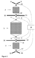
- the present invention discloses a chromatography system that comprises a main column 1 comprising a chromatography resin, a first guard column 2 and a second guard column 3, wherein the first guard column 2 is connected to a first end 4 of the main column 1, the second guard column 3 is connected to a second end 5 of the main column.
- one guard column is connected to each end of the main column.
- the bed volumes of the first and second guard columns are each less than about 50%, such as less than about 25%, less than about 15% or less than about 10%, of the bed volume of the main column 1.
- An advantage of this is that the chromatography resin is used more efficiently.
- the bed volume of the main volume can be at least one litre, such as at least 10 litres, or at least 100 litres, as there are particular advantages of using the invention in large-scale preparative chromatography for e.g. separation of biopharmaceuticals, where it is of importance to increase the resin capacity utilization.
- a first concentration detector 6 is connected between the first end 4 of the main column 1 and the first guard column 2 and a second concentration detector 7 is connected between the second end 5 of the main column 1 and the second guard column 3.
- the first and second concentration detectors can be ultraviolet absorption detectors, which are convenient for detecting the concentration of e.g. proteins. They can however also be e.g. refractive index detectors which can be used to detect non UV-absorbing substances or they can be specific detectors for various target substances or contaminants.
- An advantage of having detectors in these positions is that it is then possible to monitor the breakthrough of the main column in both upflow and downflow directions, providing a possibility to control the flowpath through the system once a breakthrough is detected. The monitoring of the breakthrough can be done manually or automatically and the controlling of the flowpath can be done manually or automatically.
- the chromatography system also comprises a determining unit 18 electrically connected to the first 6 and second 7 concentration detectors and adapted to detect a feed signal being representative of the composition of a feed material provided to one end 4,5 of the main column and an effluent signal being representative of an effluent from the opposite end the main column and an effluent signal being representative of an effluent from the opposite end 5,4 of the main column.
- the determining unit 18 can in one embodiment be adapted to determine a breakthrough point and/or a saturation point of the main column 1.
- the determining unit 18 can be a computer, a programmable logic controller or any other type of digital or analog unit capable of controlling valves depending on a function calculated from the concentration detector signals.
- Breakthrough points can be calculated by comparing the signal measured on the first detector 6 and the second detector 7.
- the signal measured on the first detector 6 represents (in the case of a UV detector) the concentration of all UV absorbing components present in the feed, i.e, both those binding to the first guard column 2 and those passing through.
- the signal reaches a first plateau when the non-adsorbing substances break through the guard column 2, and then a second plateau when the first guard column 2 becomes saturated.
- the second plateau represents the total concentration of all the substances present in the feed stream.
- the second detector 7 monitors the concentration of substances in the effluent stream from the column 1.
- the first breakthrough point is reached when the difference between the signal measured on the second detector reaches a predetermined value of for instance 1% of the difference between the second plateau measured on the first detector and the first plateau measured on the second detector.
- the second breakthrough point called the saturation point, is determined in an analogue manner with the exception that the difference between the signals measured on the two detectors reaches another value for instance 70%.
- the first guard column 2 is connected to either a feed tank 8 or a waste receptacle 9 via a first valve 10 and the second guard column 3 is connected to either a feed tank 15 or a waste receptacle 16 via a second valve 17, with the proviso that when the first guard column is connected to a feed tank, then the second guard column is connected to a waste receptacle and when the first guard column is connected to a waste receptacle, then the second guard column is connected to a feed tank.
- the determining unit 18 is electrically connected to the first and second valves and adapted to control the positions of said first and second valves.
- the chromatography system also comprises a third valve 12 between the main column 1 and the first guard column 2, with the third valve 12 adapted to divert fluid from the main column 1 to an eluate tank 11 or to waste receptacle 16, as well as a fourth valve 14 between the main column 1 and the second guard column 3, where the fourth valve 14 is adapted to divert fluid from the main column 1 to an eluate tank 13 or to waste receptacle 16, and wherein the determining unit 18 is adapted to control the positions of the third and fourth valves.
- One advantage of this arrangement is that when the determining unit detects the completion of a wash cycle, it can automatically start an elution cycle.
- a second advantage of this arrangement is that when the determining unit detects the breakthrough point, it can automatically connect the second guard column 3 in series with main column 1. This prevents the second guard column 3 from exposure to product depleted feed stream.
- said first and second guard columns comprise a chromatography resin having essentially the same selectivity as the chromatography resin in the main column.
- the resin in the guard columns and the main column bind the same substances at given conditions of ionic strength, pH etc.
- the resins can be substituted with the same type of ligand, suitably with approximately the same ligand content or with less than about 20% difference in ligand content.
- said main column and said first and second guard columns comprise a chromatography resin with Fc fragment-binding affinity ligands.
- affinity ligands are commonly used for the capture step in monoclonal antibody processing, where their high cost puts pressure on increasing the step efficiency and the lifetime of the resins. They have a very high selectivity for antibodies, allowing the use of a single step gradient for elution, which is particularly advantageous for the methods and systems of the invention.
- the affinity ligand can be a proteinaceous ligand, such as e.g. Protein A, a mutant variety of Protein A as described in e.g.
- the affinity ligand can be a peptide, nucleic acid or a small organic molecule.
- the ligand content of the resin can e.g. be in the range of 1-15 mg/ml resin.
- said first and second guard columns comprise a chromatography resin having a volume average particle size at least about 10%, such as at least about 25% or about 50%, higher than the volume average size of the chromatography resin in the main column.
- the average particle size of the main column resin can be about 50-100 microns, such as 80-95 microns, while the average particle size of the guard column resin can be about 100-250 microns, such as 130-210 microns.
- the average particle size of the resin can advantageously be the same throughout the first and second guard columns.
- the main column can be packed with the Protein A-functional MabSelect resin (GE Healthcare Life Sciences) of 85 micron average particle size and the guard columns with Sepharose Big Beads (GE Healthcare Life Sciences) of 200 micron average particle size that have been functionalized with Protein A according to methods known in the art, e.g. as described in EP873353B1 .
- An advantage of having larger particle size resin in the guard columns is that the back pressure will be lower, while the lower steepness of the breakthrough curve normally associated with larger particles is not an issue, since the guard columns do not have to be used in the vicinity of their breakthrough points.
- the present invention discloses a method for chromatographic separation of a target substance comprising the steps of:
- a target substance e.g. a biomolecule such as a protein, an immunoglobulin, IgG or a monoclonal antibody
- a target substance can be bound to a chromatography resin in the first guard column and in the main column, so that only depleted feed is conveyed to the waste receptacle. This can go on until the main column shows product breakthrough.
- the second guard column can be connected to the main column and the target substance not bound on the main column is then adsorbed on the second guard column. This process can go on until the first guard column and the main column are saturated and some target substance is bound to a chromatography resin in the second guard column.
- the flow can then be changed to the wash mode in step b), where wash fluid is conveyed through all three columns in any direction although preferably in the same direction as in step a), and any target substance leaching out complete, the flow can be changed to elution mode in step c), where the elution fluid is conveyed through one of the guard columns and the main column in any direction although preferably in the same direction as in step a), such as through the second guard column and then through the main column, to the eluate tank, where the separated target substance is collected.
- An advantage of this method is that any breakthrough target substance from the main column can be captured by a guard column both during loading and washing and then recovered during elution.
- steps b) and c) are repeated after step d), with the flow in repeated steps b) and c) being run in the opposite direction of to the flow in the original steps b) and c).
- the flow in repeated step c) is run through the second guard column and then through the main column to the eluate tank 8.
- Step a) further comprises measuring the concentration of a target substance in the fluid exiting the main column and ending step a) when said concentration has reached a predetermined value.
- step a) further comprises determining a breakthrough point or a saturation point of the main column and ending step a) when said breakthrough or saturation point has been reached.
- step b) further comprises measuring the concentration of a target substance in the fluid exiting the main column and ending step b) when said concentration is lower than a predetermined value.
Claims (14)
- Système chromatographique comprenant une colonne principale (1) comprenant une résine chromatographique, une première colonne de garde (2) et une seconde colonne de garde (3), dans lequel la première colonne de garde (2) est raccordée à une première extrémité (4) de la colonne principale (1), tandis que la seconde colonne de garde (3) est raccordée à une seconde extrémité (5) de la colonne principale,
dans lequel un premier détecteur de concentration (6) est raccordé entre ladite première extrémité (4) de la colonne principale (1) et ladite première colonne de garde (2) et un second détecteur de concentration (7) est raccordé entre ladite seconde extrémité (5) de la colonne principale (1) et ladite seconde colonne de garde (3). - Système chromatographique selon la revendication 1, dans lequel lesdits premier et second détecteurs de concentration (6, 7) sont des détecteurs absorbant les ultraviolets.
- Système chromatographique selon la revendication 1 ou la revendication 2, comprenant en outre une unité de détermination (18) connectée électriquement auxdits premier et second détecteurs de concentration et susceptible de détecter un signal d'alimentation représentatif de la composition d'un matériau d'alimentation fourni à une première extrémité (4, 5) de la colonne principale et un signal d'effluent représentatif d'un effluent sortant de l'extrémité opposée (5, 4) de la colonne principale.
- Système chromatographique selon la revendication 3, dans lequel l'unité de détermination (18) est à même de déterminer un point de rupture et/ou un point de saturation de la colonne principale (1).
- Système chromatographique selon l'une quelconque des revendications précédentes, dans lequel la première colonne de garde (2) est raccordée à un réservoir d'alimentation (8) ou à un réceptacle de rebut (9) via une première soupape (10) et la seconde colonne de garde (3) est raccordée à un réservoir d'alimentation (15) ou à un réceptacle de rebut (16) via une deuxième soupape (17), à condition que, lorsque la première colonne de garde est raccordée à un réservoir d'alimentation, la seconde colonne de garde soit raccordée à un réceptacle de rebut et que, lorsque la première colonne de garde est raccordée à un réceptacle de rebut, la seconde colonne de garde soit raccordée à un réservoir d'alimentation.
- Système chromatographique selon la revendication 5, dans lequel une unité de détermination (18) est connectée électriquement auxdites première et deuxième soupapes et est à même de commander les positions desdites première et deuxième soupapes.
- Système chromatographique selon la revendication 6, comprenant en outre une troisième soupape (12) entre la colonne principale (1) et la première colonne de garde (2), ladite troisième soupape étant à même de dévier le fluide provenant de la colonne principale (1) vers un réservoir d'éluat (11) ou vers le réceptacle de rebut (16), et une quatrième soupape (14) entre la colonne principale (1) et la seconde colonne de garde (3), ladite quatrième soupape étant à même de dévier le fluide de la colonne principale (1) vers un réservoir d'éluat (13) ou vers le réceptacle de rebut (16), et dans lequel ladite unité de détermination (18) est à même de commander les positions desdites troisième et quatrième soupapes.
- Système chromatographique selon l'une quelconque des revendications précédentes, dans lequel ladite colonne principale et lesdites première et seconde colonnes de garde comprennent une résine chromatographique avec des ligands d'affinité se liant à un fragment Fc.
- Procédé de séparation chromatographique d'une substance cible en utilisant le système de la revendication 1, comprenant les étapes consistant à :a) charger la substance cible sur une colonne principale (1) en acheminant une alimentation provenant d'un réservoir d'alimentation (8) via une première colonne de garde (2) à travers la colonne principale (1) et une seconde colonne de garde (3) vers un réceptacle de rebut (16), mesurer la concentration d'une substance cible dans le fluide sortant de la colonne principale et terminer l'étape a) lorsque ladite concentration a atteint une valeur prédéterminée,b) laver les colonnes en acheminant un fluide de lavage via la première colonne de garde (2) à travers la colonne principale (1) et la seconde colonne de garde (3),c) éluer ladite substance cible en acheminant un fluide d'élution via la première colonne de garde (2) ou la seconde colonne de garde (3) à travers la colonne principale (1) vers un réservoir d'éluat (11, 13) et éventuellement une étape consistant à :d) charger la substance cible sur la colonne principale (1) en acheminant une alimentation provenant d'un réservoir d'alimentation (15) via la seconde colonne de garde (3) à travers la colonne principale (1) et la première colonne de garde (2) vers un réceptacle de rebut (9).
- Procédé selon la revendication 9, dans lequel l'étape a) comprend en outre la détermination d'un point de rupture ou d'un point de saturation de la colonne principale en comparant le signal mesuré sur le premier détecteur (6) et le second détecteur (7) et l'achèvement de l'étape a) lorsque ledit point de rupture ou de saturation a été atteint.
- Procédé selon l'une quelconque des revendications 9 et 10, dans lequel l'étape b) comprend en outre la mesure de la concentration d'une substance cible dans le fluide sortant de la colonne principale et l'achèvement de l'étape b) lorsque ladite concentration est inférieure à une valeur prédéterminée.
- Procédé selon l'une quelconque des revendications 9 à 11, dans lequel lesdites première et seconde colonnes de garde comprennent une résine chromatographique ayant sensiblement la même sélectivité que la résine chromatographique de la colonne principale, notamment une résine chromatographique avec des ligands d'affinité se liant au fragment Fc.
- Procédé selon l'une quelconque des revendications 9 à 12, dans lequel lesdites première et seconde colonnes de garde comprennent une résine chromatographique ayant une taille particulaire moyenne en volume au moins 10 %, notamment au moins 25 % ou 50 %, plus élevée que la taille moyenne en volume de la résine chromatographique dans la colonne principale.
- Procédé selon l'une quelconque des revendications 9 à 13, dans lequel les volumes de lit de la première (2) et de la seconde (3) colonne de garde sont chacun inférieurs à environ 50 %, notamment inférieurs à environ 25 % ou inférieurs à environ 15 %, du volume de lit de la colonne principale (1).
Applications Claiming Priority (2)
| Application Number | Priority Date | Filing Date | Title |
|---|---|---|---|
| SE1051116 | 2010-10-27 | ||
| PCT/SE2011/051254 WO2012057676A1 (fr) | 2010-10-27 | 2011-10-24 | Système de chromatographie comportant des colonnes de garde |
Publications (3)
| Publication Number | Publication Date |
|---|---|
| EP2633306A1 EP2633306A1 (fr) | 2013-09-04 |
| EP2633306A4 EP2633306A4 (fr) | 2014-10-08 |
| EP2633306B1 true EP2633306B1 (fr) | 2016-03-23 |
Family
ID=45994166
Family Applications (1)
| Application Number | Title | Priority Date | Filing Date |
|---|---|---|---|
| EP11836717.6A Active EP2633306B1 (fr) | 2010-10-27 | 2011-10-24 | Système de chromatographie comportant des colonnes de garde |
Country Status (5)
| Country | Link |
|---|---|
| US (3) | US20130213884A1 (fr) |
| EP (1) | EP2633306B1 (fr) |
| JP (1) | JP5879357B2 (fr) |
| CN (1) | CN103180727B (fr) |
| WO (1) | WO2012057676A1 (fr) |
Families Citing this family (8)
| Publication number | Priority date | Publication date | Assignee | Title |
|---|---|---|---|---|
| DE102014010353A1 (de) * | 2014-07-10 | 2016-01-14 | Sartorius Stedim Biotech Gmbh | Vorrichtung, Verwendung dieser Vorrichtung und Verfahren für die Stofftrennung mit verbesserter Ausnutzung der Kapazität chromatographischer Medien |
| GB201511463D0 (en) | 2015-06-30 | 2015-08-12 | Ge Healthcare Bio Sciences Ab | Improvements in and relating to fluid path networks |
| US11835501B2 (en) * | 2015-07-13 | 2023-12-05 | Sartorius Stedim Chromatography Systems Ltd. | Optimizing operating binding capacity for a multiple column chromatography process |
| GB201517282D0 (en) * | 2015-09-30 | 2015-11-11 | Ge Healthcare Bio Sciences Ab | A chromatography system and a method therefor |
| JP6206468B2 (ja) * | 2015-11-11 | 2017-10-04 | ダイキン工業株式会社 | スクロール圧縮機 |
| GB201602938D0 (en) * | 2016-02-19 | 2016-04-06 | Ucb Biopharma Sprl | Protein purification |
| KR20210045413A (ko) * | 2018-08-17 | 2021-04-26 | 리제너론 파마슈티칼스 인코포레이티드 | 다량체 단백질의 양 및 순도를 측정하기 위한 방법 및 크로마토그래피 시스템 |
| GB201909274D0 (en) * | 2019-06-27 | 2019-08-14 | Ge Healthcare Bio Sciences Ab | Method in bioprocess purification system |
Family Cites Families (15)
| Publication number | Priority date | Publication date | Assignee | Title |
|---|---|---|---|---|
| JPS60142251A (ja) * | 1983-12-29 | 1985-07-27 | Shimadzu Corp | ガ−ドカラム充てん法 |
| US4826603A (en) * | 1986-09-09 | 1989-05-02 | United States Of America As Represented By The Secretary Of The Air Force | Hydrocarbon group-type analyzer system |
| US4851355A (en) * | 1987-06-05 | 1989-07-25 | Hayes Jr Paul C | Hydrocarbon group-type analyzer system |
| CN2094745U (zh) * | 1991-06-22 | 1992-01-29 | 中国科学院大连化学物理研究所 | 一种带保护柱的高效液相色谱柱 |
| JP3053131B2 (ja) | 1991-09-17 | 2000-06-19 | 株式会社日立製作所 | ガードカラムを備えた高速液体クロマトグラフ |
| US5651885A (en) * | 1994-04-15 | 1997-07-29 | Schick; Hans G. | Column for liquid chromatography |
| DE69627333T2 (de) * | 1995-06-26 | 2004-02-12 | PerSeptive Biosystems, Inc., Framingham | Automatisierte, kontinuierliche mehrdimensionale hochgeschwindigkeitsmolekularselektion und -analyse |
| DE10049079A1 (de) * | 2000-10-02 | 2002-04-18 | Merck Patent Gmbh | Verfahren und System zur Methodenoptimierung in der Chromatographie |
| US7691645B2 (en) * | 2001-01-09 | 2010-04-06 | Agilent Technologies, Inc. | Immunosubtraction method |
| JP3996550B2 (ja) * | 2003-05-28 | 2007-10-24 | 株式会社日立ハイテクノロジーズ | アミノ酸分析装置 |
| JP4504721B2 (ja) * | 2004-04-07 | 2010-07-14 | オルガノ株式会社 | 液体クロマトグラフィー装置 |
| US20060157647A1 (en) * | 2005-01-18 | 2006-07-20 | Becton, Dickinson And Company | Multidimensional liquid chromatography/spectrometry |
| US7520920B1 (en) | 2005-03-04 | 2009-04-21 | Griffin Analytical Technologies | Guard columns for gas chromatographs and gas chromatograph-mass spectrometers |
| CA2664530C (fr) * | 2006-09-29 | 2015-11-17 | Ge Healthcare Bio-Sciences Ab | Ligand de chromatographie comprenant un domaine c issu de la proteine a de staphylococcus aureus pour l'isolement d'anticorps |
| WO2009023268A1 (fr) * | 2007-08-16 | 2009-02-19 | Alltech Associates Inc. | Assemblages de colonnes de chromatographie |
-
2011
- 2011-10-24 EP EP11836717.6A patent/EP2633306B1/fr active Active
- 2011-10-24 CN CN201180051833.5A patent/CN103180727B/zh active Active
- 2011-10-24 JP JP2013536561A patent/JP5879357B2/ja active Active
- 2011-10-24 WO PCT/SE2011/051254 patent/WO2012057676A1/fr active Application Filing
- 2011-10-24 US US13/881,801 patent/US20130213884A1/en not_active Abandoned
-
2018
- 2018-08-06 US US16/056,339 patent/US20180340917A1/en not_active Abandoned
-
2020
- 2020-11-24 US US17/102,865 patent/US20210080434A1/en active Pending
Also Published As
| Publication number | Publication date |
|---|---|
| CN103180727B (zh) | 2015-12-16 |
| CN103180727A (zh) | 2013-06-26 |
| EP2633306A4 (fr) | 2014-10-08 |
| EP2633306A1 (fr) | 2013-09-04 |
| US20180340917A1 (en) | 2018-11-29 |
| JP5879357B2 (ja) | 2016-03-08 |
| JP2014501911A (ja) | 2014-01-23 |
| US20130213884A1 (en) | 2013-08-22 |
| WO2012057676A1 (fr) | 2012-05-03 |
| US20210080434A1 (en) | 2021-03-18 |
Similar Documents
| Publication | Publication Date | Title |
|---|---|---|
| US20210080434A1 (en) | Chromatography System with Guard Columns | |
| EP2675540B1 (fr) | Système et procédé de chromatographie d'un biopolymère | |
| EP2160227B1 (fr) | Procédé de chromatographie | |
| AU2006329963B2 (en) | Polishing steps used in multi-step protein purification processes | |
| KR101790700B1 (ko) | 관류 공정의 용량을 증가시키는 방법 | |
| Pathak et al. | Mechanistic understanding of fouling of protein A chromatography resin | |
| Hall | Size exclusion chromatography (SEC) | |
| EP3585495B1 (fr) | Procédé en chromatographie continue | |
| US10843104B2 (en) | System and process for biopolymer chromatography | |
| US10669307B2 (en) | Device, use of said device, and method for separating substances with an improved utilization of the capacity of chromatographic media | |
| US20160074775A1 (en) | Continuous chromatography method and system | |
| Liu et al. | Evaluation of chromatofocusing as a capture method for monoclonal antibody products | |
| US20160074774A1 (en) | Chromatography method and system | |
| Yoshimoto et al. | Connected flow-through chromatography processes as continuous downstream processing of proteins | |
| Wysor et al. | Alleviation of the necessity for supernatant prefiltering in the protein a recovery of Monoclonal antibodies from Chinese hamster ovary cell cultures | |
| Silva et al. | Digital twin in high throughput chromatographic process development for monoclonal antibodies | |
| Mora et al. | Membrane chromatography |
Legal Events
| Date | Code | Title | Description |
|---|---|---|---|
| PUAI | Public reference made under article 153(3) epc to a published international application that has entered the european phase |
Free format text: ORIGINAL CODE: 0009012 |
|
| 17P | Request for examination filed |
Effective date: 20130418 |
|
| AK | Designated contracting states |
Kind code of ref document: A1 Designated state(s): AL AT BE BG CH CY CZ DE DK EE ES FI FR GB GR HR HU IE IS IT LI LT LU LV MC MK MT NL NO PL PT RO RS SE SI SK SM TR |
|
| DAX | Request for extension of the european patent (deleted) | ||
| A4 | Supplementary search report drawn up and despatched |
Effective date: 20140910 |
|
| RIC1 | Information provided on ipc code assigned before grant |
Ipc: G01N 30/46 20060101AFI20140904BHEP Ipc: G01N 30/88 20060101ALI20140904BHEP Ipc: G01N 30/60 20060101ALI20140904BHEP Ipc: B01D 15/18 20060101ALI20140904BHEP |
|
| 17Q | First examination report despatched |
Effective date: 20141022 |
|
| GRAP | Despatch of communication of intention to grant a patent |
Free format text: ORIGINAL CODE: EPIDOSNIGR1 |
|
| INTG | Intention to grant announced |
Effective date: 20151012 |
|
| GRAS | Grant fee paid |
Free format text: ORIGINAL CODE: EPIDOSNIGR3 |
|
| GRAA | (expected) grant |
Free format text: ORIGINAL CODE: 0009210 |
|
| AK | Designated contracting states |
Kind code of ref document: B1 Designated state(s): AL AT BE BG CH CY CZ DE DK EE ES FI FR GB GR HR HU IE IS IT LI LT LU LV MC MK MT NL NO PL PT RO RS SE SI SK SM TR |
|
| REG | Reference to a national code |
Ref country code: GB Ref legal event code: FG4D |
|
| REG | Reference to a national code |
Ref country code: CH Ref legal event code: EP |
|
| REG | Reference to a national code |
Ref country code: AT Ref legal event code: REF Ref document number: 783651 Country of ref document: AT Kind code of ref document: T Effective date: 20160415 |
|
| REG | Reference to a national code |
Ref country code: IE Ref legal event code: FG4D |
|
| REG | Reference to a national code |
Ref country code: DE Ref legal event code: R096 Ref document number: 602011024442 Country of ref document: DE |
|
| REG | Reference to a national code |
Ref country code: LT Ref legal event code: MG4D |
|
| REG | Reference to a national code |
Ref country code: NL Ref legal event code: MP Effective date: 20160323 |
|
| PG25 | Lapsed in a contracting state [announced via postgrant information from national office to epo] |
Ref country code: GR Free format text: LAPSE BECAUSE OF FAILURE TO SUBMIT A TRANSLATION OF THE DESCRIPTION OR TO PAY THE FEE WITHIN THE PRESCRIBED TIME-LIMIT Effective date: 20160624 Ref country code: HR Free format text: LAPSE BECAUSE OF FAILURE TO SUBMIT A TRANSLATION OF THE DESCRIPTION OR TO PAY THE FEE WITHIN THE PRESCRIBED TIME-LIMIT Effective date: 20160323 Ref country code: NO Free format text: LAPSE BECAUSE OF FAILURE TO SUBMIT A TRANSLATION OF THE DESCRIPTION OR TO PAY THE FEE WITHIN THE PRESCRIBED TIME-LIMIT Effective date: 20160623 Ref country code: FI Free format text: LAPSE BECAUSE OF FAILURE TO SUBMIT A TRANSLATION OF THE DESCRIPTION OR TO PAY THE FEE WITHIN THE PRESCRIBED TIME-LIMIT Effective date: 20160323 |
|
| REG | Reference to a national code |
Ref country code: AT Ref legal event code: MK05 Ref document number: 783651 Country of ref document: AT Kind code of ref document: T Effective date: 20160323 |
|
| PG25 | Lapsed in a contracting state [announced via postgrant information from national office to epo] |
Ref country code: SE Free format text: LAPSE BECAUSE OF FAILURE TO SUBMIT A TRANSLATION OF THE DESCRIPTION OR TO PAY THE FEE WITHIN THE PRESCRIBED TIME-LIMIT Effective date: 20160323 Ref country code: RS Free format text: LAPSE BECAUSE OF FAILURE TO SUBMIT A TRANSLATION OF THE DESCRIPTION OR TO PAY THE FEE WITHIN THE PRESCRIBED TIME-LIMIT Effective date: 20160323 Ref country code: NL Free format text: LAPSE BECAUSE OF FAILURE TO SUBMIT A TRANSLATION OF THE DESCRIPTION OR TO PAY THE FEE WITHIN THE PRESCRIBED TIME-LIMIT Effective date: 20160323 Ref country code: LV Free format text: LAPSE BECAUSE OF FAILURE TO SUBMIT A TRANSLATION OF THE DESCRIPTION OR TO PAY THE FEE WITHIN THE PRESCRIBED TIME-LIMIT Effective date: 20160323 Ref country code: LT Free format text: LAPSE BECAUSE OF FAILURE TO SUBMIT A TRANSLATION OF THE DESCRIPTION OR TO PAY THE FEE WITHIN THE PRESCRIBED TIME-LIMIT Effective date: 20160323 |
|
| REG | Reference to a national code |
Ref country code: FR Ref legal event code: PLFP Year of fee payment: 6 |
|
| PG25 | Lapsed in a contracting state [announced via postgrant information from national office to epo] |
Ref country code: IS Free format text: LAPSE BECAUSE OF FAILURE TO SUBMIT A TRANSLATION OF THE DESCRIPTION OR TO PAY THE FEE WITHIN THE PRESCRIBED TIME-LIMIT Effective date: 20160723 Ref country code: EE Free format text: LAPSE BECAUSE OF FAILURE TO SUBMIT A TRANSLATION OF THE DESCRIPTION OR TO PAY THE FEE WITHIN THE PRESCRIBED TIME-LIMIT Effective date: 20160323 Ref country code: PL Free format text: LAPSE BECAUSE OF FAILURE TO SUBMIT A TRANSLATION OF THE DESCRIPTION OR TO PAY THE FEE WITHIN THE PRESCRIBED TIME-LIMIT Effective date: 20160323 |
|
| PG25 | Lapsed in a contracting state [announced via postgrant information from national office to epo] |
Ref country code: CZ Free format text: LAPSE BECAUSE OF FAILURE TO SUBMIT A TRANSLATION OF THE DESCRIPTION OR TO PAY THE FEE WITHIN THE PRESCRIBED TIME-LIMIT Effective date: 20160323 Ref country code: PT Free format text: LAPSE BECAUSE OF FAILURE TO SUBMIT A TRANSLATION OF THE DESCRIPTION OR TO PAY THE FEE WITHIN THE PRESCRIBED TIME-LIMIT Effective date: 20160725 Ref country code: SK Free format text: LAPSE BECAUSE OF FAILURE TO SUBMIT A TRANSLATION OF THE DESCRIPTION OR TO PAY THE FEE WITHIN THE PRESCRIBED TIME-LIMIT Effective date: 20160323 Ref country code: SM Free format text: LAPSE BECAUSE OF FAILURE TO SUBMIT A TRANSLATION OF THE DESCRIPTION OR TO PAY THE FEE WITHIN THE PRESCRIBED TIME-LIMIT Effective date: 20160323 Ref country code: AT Free format text: LAPSE BECAUSE OF FAILURE TO SUBMIT A TRANSLATION OF THE DESCRIPTION OR TO PAY THE FEE WITHIN THE PRESCRIBED TIME-LIMIT Effective date: 20160323 Ref country code: RO Free format text: LAPSE BECAUSE OF FAILURE TO SUBMIT A TRANSLATION OF THE DESCRIPTION OR TO PAY THE FEE WITHIN THE PRESCRIBED TIME-LIMIT Effective date: 20160323 Ref country code: ES Free format text: LAPSE BECAUSE OF FAILURE TO SUBMIT A TRANSLATION OF THE DESCRIPTION OR TO PAY THE FEE WITHIN THE PRESCRIBED TIME-LIMIT Effective date: 20160323 |
|
| PG25 | Lapsed in a contracting state [announced via postgrant information from national office to epo] |
Ref country code: IT Free format text: LAPSE BECAUSE OF FAILURE TO SUBMIT A TRANSLATION OF THE DESCRIPTION OR TO PAY THE FEE WITHIN THE PRESCRIBED TIME-LIMIT Effective date: 20160323 Ref country code: BE Free format text: LAPSE BECAUSE OF FAILURE TO SUBMIT A TRANSLATION OF THE DESCRIPTION OR TO PAY THE FEE WITHIN THE PRESCRIBED TIME-LIMIT Effective date: 20160323 |
|
| REG | Reference to a national code |
Ref country code: DE Ref legal event code: R097 Ref document number: 602011024442 Country of ref document: DE |
|
| PLBE | No opposition filed within time limit |
Free format text: ORIGINAL CODE: 0009261 |
|
| STAA | Information on the status of an ep patent application or granted ep patent |
Free format text: STATUS: NO OPPOSITION FILED WITHIN TIME LIMIT |
|
| PG25 | Lapsed in a contracting state [announced via postgrant information from national office to epo] |
Ref country code: DK Free format text: LAPSE BECAUSE OF FAILURE TO SUBMIT A TRANSLATION OF THE DESCRIPTION OR TO PAY THE FEE WITHIN THE PRESCRIBED TIME-LIMIT Effective date: 20160323 |
|
| PG25 | Lapsed in a contracting state [announced via postgrant information from national office to epo] |
Ref country code: BG Free format text: LAPSE BECAUSE OF FAILURE TO SUBMIT A TRANSLATION OF THE DESCRIPTION OR TO PAY THE FEE WITHIN THE PRESCRIBED TIME-LIMIT Effective date: 20160623 |
|
| 26N | No opposition filed |
Effective date: 20170102 |
|
| PG25 | Lapsed in a contracting state [announced via postgrant information from national office to epo] |
Ref country code: SI Free format text: LAPSE BECAUSE OF FAILURE TO SUBMIT A TRANSLATION OF THE DESCRIPTION OR TO PAY THE FEE WITHIN THE PRESCRIBED TIME-LIMIT Effective date: 20160323 |
|
| REG | Reference to a national code |
Ref country code: CH Ref legal event code: PL |
|
| REG | Reference to a national code |
Ref country code: IE Ref legal event code: MM4A |
|
| PG25 | Lapsed in a contracting state [announced via postgrant information from national office to epo] |
Ref country code: LI Free format text: LAPSE BECAUSE OF NON-PAYMENT OF DUE FEES Effective date: 20161031 Ref country code: CH Free format text: LAPSE BECAUSE OF NON-PAYMENT OF DUE FEES Effective date: 20161031 |
|
| PG25 | Lapsed in a contracting state [announced via postgrant information from national office to epo] |
Ref country code: LU Free format text: LAPSE BECAUSE OF NON-PAYMENT OF DUE FEES Effective date: 20161024 |
|
| REG | Reference to a national code |
Ref country code: FR Ref legal event code: PLFP Year of fee payment: 7 |
|
| PG25 | Lapsed in a contracting state [announced via postgrant information from national office to epo] |
Ref country code: IE Free format text: LAPSE BECAUSE OF NON-PAYMENT OF DUE FEES Effective date: 20161024 |
|
| PG25 | Lapsed in a contracting state [announced via postgrant information from national office to epo] |
Ref country code: CY Free format text: LAPSE BECAUSE OF FAILURE TO SUBMIT A TRANSLATION OF THE DESCRIPTION OR TO PAY THE FEE WITHIN THE PRESCRIBED TIME-LIMIT Effective date: 20160323 Ref country code: HU Free format text: LAPSE BECAUSE OF FAILURE TO SUBMIT A TRANSLATION OF THE DESCRIPTION OR TO PAY THE FEE WITHIN THE PRESCRIBED TIME-LIMIT; INVALID AB INITIO Effective date: 20111024 |
|
| PG25 | Lapsed in a contracting state [announced via postgrant information from national office to epo] |
Ref country code: MK Free format text: LAPSE BECAUSE OF FAILURE TO SUBMIT A TRANSLATION OF THE DESCRIPTION OR TO PAY THE FEE WITHIN THE PRESCRIBED TIME-LIMIT Effective date: 20160323 Ref country code: MC Free format text: LAPSE BECAUSE OF FAILURE TO SUBMIT A TRANSLATION OF THE DESCRIPTION OR TO PAY THE FEE WITHIN THE PRESCRIBED TIME-LIMIT Effective date: 20160323 Ref country code: MT Free format text: LAPSE BECAUSE OF NON-PAYMENT OF DUE FEES Effective date: 20161031 |
|
| REG | Reference to a national code |
Ref country code: FR Ref legal event code: PLFP Year of fee payment: 8 |
|
| PG25 | Lapsed in a contracting state [announced via postgrant information from national office to epo] |
Ref country code: AL Free format text: LAPSE BECAUSE OF FAILURE TO SUBMIT A TRANSLATION OF THE DESCRIPTION OR TO PAY THE FEE WITHIN THE PRESCRIBED TIME-LIMIT Effective date: 20160323 Ref country code: TR Free format text: LAPSE BECAUSE OF FAILURE TO SUBMIT A TRANSLATION OF THE DESCRIPTION OR TO PAY THE FEE WITHIN THE PRESCRIBED TIME-LIMIT Effective date: 20160323 |
|
| REG | Reference to a national code |
Ref country code: DE Ref legal event code: R081 Ref document number: 602011024442 Country of ref document: DE Owner name: CYTIVA SWEDEN AB, SE Free format text: FORMER OWNER: GE HEALTHCARE BIO-SCIENCES AB, UPPSALA, SE |
|
| P01 | Opt-out of the competence of the unified patent court (upc) registered |
Effective date: 20230526 |
|
| PGFP | Annual fee paid to national office [announced via postgrant information from national office to epo] |
Ref country code: GB Payment date: 20230831 Year of fee payment: 13 |
|
| PGFP | Annual fee paid to national office [announced via postgrant information from national office to epo] |
Ref country code: FR Payment date: 20230911 Year of fee payment: 13 |
|
| PGFP | Annual fee paid to national office [announced via postgrant information from national office to epo] |
Ref country code: DE Payment date: 20230830 Year of fee payment: 13 |