EP2633234B1 - Rückvermischungsvorrichtung für pneumatische fördersysteme - Google Patents
Rückvermischungsvorrichtung für pneumatische fördersysteme Download PDFInfo
- Publication number
- EP2633234B1 EP2633234B1 EP11758627.1A EP11758627A EP2633234B1 EP 2633234 B1 EP2633234 B1 EP 2633234B1 EP 11758627 A EP11758627 A EP 11758627A EP 2633234 B1 EP2633234 B1 EP 2633234B1
- Authority
- EP
- European Patent Office
- Prior art keywords
- back mixing
- solids
- flow
- mixing device
- pneumatic conveying
- Prior art date
- Legal status (The legal status is an assumption and is not a legal conclusion. Google has not performed a legal analysis and makes no representation as to the accuracy of the status listed.)
- Active
Links
Images


Classifications
-
- B—PERFORMING OPERATIONS; TRANSPORTING
- B01—PHYSICAL OR CHEMICAL PROCESSES OR APPARATUS IN GENERAL
- B01F—MIXING, e.g. DISSOLVING, EMULSIFYING OR DISPERSING
- B01F25/00—Flow mixers; Mixers for falling materials, e.g. solid particles
- B01F25/40—Static mixers
-
- B—PERFORMING OPERATIONS; TRANSPORTING
- B65—CONVEYING; PACKING; STORING; HANDLING THIN OR FILAMENTARY MATERIAL
- B65G—TRANSPORT OR STORAGE DEVICES, e.g. CONVEYORS FOR LOADING OR TIPPING, SHOP CONVEYOR SYSTEMS OR PNEUMATIC TUBE CONVEYORS
- B65G53/00—Conveying materials in bulk through troughs, pipes or tubes by floating the materials or by flow of gas, liquid or foam
- B65G53/04—Conveying materials in bulk pneumatically through pipes or tubes; Air slides
- B65G53/16—Gas pressure systems operating with fluidisation of the materials
-
- B—PERFORMING OPERATIONS; TRANSPORTING
- B01—PHYSICAL OR CHEMICAL PROCESSES OR APPARATUS IN GENERAL
- B01F—MIXING, e.g. DISSOLVING, EMULSIFYING OR DISPERSING
- B01F23/00—Mixing according to the phases to be mixed, e.g. dispersing or emulsifying
- B01F23/60—Mixing solids with solids
-
- B—PERFORMING OPERATIONS; TRANSPORTING
- B01—PHYSICAL OR CHEMICAL PROCESSES OR APPARATUS IN GENERAL
- B01F—MIXING, e.g. DISSOLVING, EMULSIFYING OR DISPERSING
- B01F25/00—Flow mixers; Mixers for falling materials, e.g. solid particles
- B01F25/40—Static mixers
- B01F25/42—Static mixers in which the mixing is affected by moving the components jointly in changing directions, e.g. in tubes provided with baffles or obstructions
- B01F25/43—Mixing tubes, e.g. wherein the material is moved in a radial or partly reversed direction
- B01F25/433—Mixing tubes wherein the shape of the tube influences the mixing, e.g. mixing tubes with varying cross-section or provided with inwardly extending profiles
- B01F25/4338—Mixers with a succession of converging-diverging cross-sections, i.e. undulating cross-section
-
- F—MECHANICAL ENGINEERING; LIGHTING; HEATING; WEAPONS; BLASTING
- F23—COMBUSTION APPARATUS; COMBUSTION PROCESSES
- F23K—FEEDING FUEL TO COMBUSTION APPARATUS
- F23K3/00—Feeding or distributing of lump or pulverulent fuel to combustion apparatus
- F23K3/02—Pneumatic feeding arrangements, i.e. by air blast
-
- F—MECHANICAL ENGINEERING; LIGHTING; HEATING; WEAPONS; BLASTING
- F23—COMBUSTION APPARATUS; COMBUSTION PROCESSES
- F23K—FEEDING FUEL TO COMBUSTION APPARATUS
- F23K2203/00—Feeding arrangements
- F23K2203/006—Fuel distribution and transport systems for pulverulent fuel
-
- F—MECHANICAL ENGINEERING; LIGHTING; HEATING; WEAPONS; BLASTING
- F23—COMBUSTION APPARATUS; COMBUSTION PROCESSES
- F23K—FEEDING FUEL TO COMBUSTION APPARATUS
- F23K2203/00—Feeding arrangements
- F23K2203/10—Supply line fittings
Definitions
- the present invention relates generally to pneumatic conveying systems and more particularly relates to an in-line back mixing device for producing a steady flow of solids in pneumatic conveying systems such as those used in gasification systems and the like.
- Known integrated gasification combined cycle (“IGCC”) power generation systems may include a gasification system that is integrated with at least one power producing turbine system.
- known gasifiers may convert a mixture of a fuel such as coal with air or oxygen, steam, and other additives into an output of a partially combusted gas, typically referred to as synthesis gas or "syngas". These hot partially combusted gases typically are scrubbed using conventional technologies to remove contaminates and then supplied to a combustor of a gas turbine engine.
- the gas turbine engine powers a generator for the production of electrical power or to drive another type of load.
- Exhaust from the gas turbine engine may be supplied to a heat recovery steam generator so as to generate steam for a steam turbine.
- the power generated by the steam turbine also may drive an electrical generator or another type of load. Similar types of power generation systems may be known.
- a conveying system generally requires a conveying system to deliver a relatively steady flow rate of coal to the gasifier to ensure consistent performance.
- One known type of conveying system is a pneumatic conveying system in which finely ground particles of coal are conveyed through a conduit to the gasifier using a flow of gas such as nitrogen, carbon dioxide, or natural gas as the transport medium or carrier gas.
- the flow rate of coal, or any other type of conveyed solids in a pneumatic conveying system generally may exhibit varying fluctuations. These solids flow rate fluctuations may be a result of a flow separation between the solids and the carrier gas that can be caused by elements of the pneumatic conveying system itself.
- a plot versus time of the flow rate of solids past a fixed point along the conduit may take the shape of an irregular wave form with the peaks representing regions of solids enriched carrier gas and the troughs representing regions of solids depleted gas.
- Flow rate fluctuations may also be caused by other elements of a pneumatic conveying system such as the solids pressurization equipment.
- Such equipment by its very nature, may cause aggregation or agglomeration of particles that can give rise to pulses in solids concentration downstream of the pressurization device.
- Such an unsteady flow rate as described above, may lead to poor gasifier control and hence poor gasifier performance in the form of lower carbon conversions and the like.
- Such an improved pneumatic conveying system may provide a steady flow rate of solids, such as coal, which in turn may provide improved overall gasifier performance and, hence, improved power plant performance.
- a backmixing device according to the preamble of claim 1 is disclosed in GB 2 096 911 A .
- the present invention provides a back mixing device for use with a flow of solids having a varying flow rate according to claim 1.
- the present invention further provides a pneumatic conveying system for use with a gasification system according to claim 6.
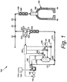
- Fig. 1 shows portions of a pneumatic conveying system 100 as described herein for use with at least a portion of a gasification system 105 and the like.
- the pneumatic conveying system 100 includes a coal source 110 with an amount of coal 120 therein.
- the coal source 110 may have any desired size or shape.
- the coal source 110 may contain any type of coal, petroleum coke, solid biomass, other solid carbonaceous fuels, or mixtures thereof (all of which are referred to as "coal 120").
- the coal 120 may be ground or otherwise prepared before use including being mixed with other ground particulate matter, such as non-carbonaceous mineral matter, that may be added to enhance the gasification characteristics of the coal in the gasifier.
- the pneumatic conveying system 100 includes a solids feeder 130 positioned downstream of and in communication with the coal source 110.
- the solids feeder 130 may be a rotary, converging channel solids pressurizing and metering device such as the Posimetric® Feeder, a particulate solids feeding pump offered by the GE Energy Division of the General Electric Company of Schenectady, New York. Other types of solids feeders or solids pumps may be used herein.
- the solids feeder 130 may be driven by a motor 140 with a speed controller 150.
- the solids feeder 130 may pressurize solids from atmospheric pressure to pressures well over 1000 psig (about 70 kg/cm 2 ). Other configurations may be used herein.
- the pneumatic conveying system 100 further may include a high pressure feed vessel 160 positioned downstream of the solids feeder 130.
- the high pressure feed vessel 160 mixes a flow of solids 170 from the solids feeder 130 with a flow of a conveying gas 180, a flow of a pressure control gas 190, and/or a flow of a fluidizing gas 200.
- the high pressure feed vessel 160 may be of conventional design.
- the high pressure feed vessel 160 fluidizes the flow of solids 170 and enhances the flow characteristics thereof.
- the flow of solids 170 may exit the high pressure feed vessel 160 via one or more discharge lines 205.
- the high pressure feed vessel 160 serves as a buffer between the solids feeder 130 and a gasifier fuel injector as is described below.
- the high pressure feed vessel 160 is an alternative flow path that may be used to improve the flow of solids 170 in the pneumatic conveying system 100 particularly if the solids feeder 130 is not a Posimetric® feeder as is described above or a similar device.
- the flow of the conveying gas 180 may be used to channel the flow of the solids 170 out of the high pressure feed vessel 160 and into the discharge line 205 to the pneumatic conveying line 215. Flow control may be achieved by adjusting the operational speed of solids feeder 130 and by adjusting the flow rates of the conveying gas stream 180 channeled to the high pressure feed vessel 160.
- the flow of the conveying gas 180 may be routed via a line 185 to channel the flow of solids 170 directly from the exit of solids feeder 130 to the conveying line 215 via a bypass line 175.
- flow control may be achieved by adjusting the operational speed of the solids feeder 130 and by adjusting the flow rate of the conveying gas stream 180 channeled via the line 185 to the exit of solids feeder 130.
- Other configurations may be used herein.
- the pneumatic conveying system 100 further may include a flow meter 210 positioned downstream of the solids feeder 130 and the high pressure feed vessel 160.
- the flow meter 210 may be of conventional design that is suitable for measuring the flow rate of pneumatically conveyed solids and may include a flow element 220, a flow transmitter 230, and/or other components. Other types of flow measurement devices may be used herein.
- the output of the flow meter 210 may be communicated to a controller 240.
- the controller 240 may be any type of conventional microprocessor and the like.
- the controller 240 may be in communication with the speed controller 150 of the solids feeder 130 as well as a number of flow control valves 250 in communication with the flow of the conveying gas 180, the flow of the pressure control gas 190, and the flow of the fluidizing gas 200.
- the controller 240 controls the speed of the flow of solids 170 as may be desired. Any other type of control device may be used herein.
- the pneumatic conveying system 100 also includes a gasifier 260, only a portion of which is shown.
- the gasifier 260 is positioned downstream of the flow meter 210.
- the gasifier 260 may be of conventional design and may include a fuel injector 270 or other type of intake device.
- the flow of solids 170 conveyed to the gasifier 260 reacts with oxygen, water, and possibly other reactants to generate a syngas product via well known, controlled chemical reactions.
- the pneumatic conveying system 100 also includes one or more back mixing devices 300.
- a first back mixing device 310 may be positioned upstream of the flow meter 210.
- the first back mixing device 310 may smooth the flow of solids 170 prior to the flow meter 210 so as to improve the control of the solids feeder 130 and the high pressure feed vessel 160, if used, via the controller 240.
- a second back mixing device 320 may be positioned upstream of the fuel injector 270 of the gasifier 260.
- the second back mixing device 320 may smooth any flow instabilities that develop between the flow meter 210 and the fuel injector 270 so as to insure a steady flow rate of solids 170 into and through the injector 270.
- Any number of back mixing devices 300 may be used herein with any type of flow of solids 170.
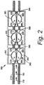
- Fig. 2 shows an embodiment of the back mixing device 300.
- the back mixing device 300 may be positioned within the pneumatic conveying line 215 with the flow of solids 170 and the flow of the conveying gas 180 or other gases therein.
- the back mixing device 300 includes one or more back mixing chambers 340.
- a first back mixing chamber 350, a second back mixing chamber 360, and a third back mixing chamber 365 are shown although any number of the chambers 340 may be used.
- Each back mixing chamber 340 includes a nozzle 370 on one end thereof and an exit 375 at the other.
- the chamber 340 forms an expanded area 380 about the nozzle 370 and a restriction 390 about the exit 375.
- the nozzle 370 may have a constricting shape extending in the downstream direction while the chamber 340 has a generally spherical shape 385 with the expanded area 380 leading to the restriction 390 before ending at the exit 375.
- the mixing chambers 340 may have any size or volume.
- the flow of solids 170 thus encounters a change in the cross-sectional area of the conveying line 215 as the flow is first constricted in the nozzle 370 and then expanded within the chamber 340 before encountering the restriction 390 and the exit 375.
- the change in cross-sectional area thus creates a number of recirculation patterns 395 that promote axial back mixing.
- This back mixing promotes stability in the flow rate of the solids 170 over time. Further stability is promoted via the use of the additional chambers 360, 365.
- the design of the back mixing device 300 thus may be optimized via combinations of the shape and volume of the chambers 340 as well as the number of chambers 340 and/or other parameters.
- Fig. 3 shows an alternative embodiment of a back mixing device 400.
- the back mixing device 400 includes a nozzle 410 leading to a chamber 420.
- the chamber 420 has a largely cylindrical shape 425 with a hemispherically expanded area 430 that leads to a conical restriction 435 at an exit 440 thereof.
- the chamber 420 largely has the shape of a reaction chamber within the gasifier 260.
- the combination of the shape of the chamber 420 and the restriction 435 may develop a strong recirculation pattern 445 in the flow of solids 170 therein. Additional chambers 420 also may be used herein.
- the design of the back mixing device 400 may be optimized via the volume of the chambers 420 as well as the number of chambers 420.
- Fig. 4 shows a further embodiment of a back mixing device 450.
- the back mixing device 450 also includes a nozzle 460 leading to a chamber 470 with an expanded area 475 leading to a restriction 480 about an exit 490.
- the back mixing device 450 also may have one or more back mixing gas lines 500.
- the back mixing gas lines 500 may include a nozzle line 510, an upstream line 520, and/or a downstream line 530. One or more of the back mixing gas lines 500 may be used together.
- the nozzle line 510 also joins the nozzle 460 so as to disperse further the incoming flow of solids 170 into a dispersion pattern 465 with a flow of a back mixing gas 540 before and during entry into the chamber 470.
- the back mixing gas 540 may be introduced into the chamber 470 at an upstream end so as to create an upstream recirculation pattern 550.
- the back mixing gas 540 may be introduced to a downstream portion of the chamber 470 to create a downstream recirculation pattern 560.
- the back mixing gas 540 through the downstream line 530 may force the flow of solids 170 to deviate from the exit 490 and to recirculate within the chamber 470. Similar types of gas entry points and configurations may be used herein.
- the back mixing devices 300 described herein thus provide flow stability for the flow of solids 170 leaving either the solids feeder 130 or the high pressure feed vessel 160.
- the back mixing devices 300 smooth out the unsteady flow rate by providing one or more chambers 340 to enhance axial back mixing therein. Any type of solids flow may be used herein.
- Fig. 5 illustrates the effect that a back mixing device, as described herein, may generally have on the stability of the solids flow rate in a given pneumatic conveying system.
- a back mixing device 300 is positioned within the pneumatic conveying line 215 having a flow of solids 170 and a flow of conveying gas 180 therein.
- the graph 172 shows the fluctuations over time in the flow of solids 170 at a point U upstream of the back mixing device 300.
- the irregular waveform represents the flow rate of solids carried by the conveying gas as it flows past point U, with the peaks representing solids enriched carrier gas and the troughs representing solids depleted gas. As described above, these fluctuations in solids flow may be caused by elements within the pneumatic conveying system itself.
- the graph 174 is similar to graph 172, except that it shows the fluctuations in solids flow rate at a point D downstream of the back mixing device 300.
- point D both the magnitude and the frequency of the fluctuations in solids flow have decreased due to the effect of the solids back mixing device.
- the recirculation patterns generated inside the back mixing device facilitate mixing between regions of solids enriched and solids depleted conveying gas. In doing so, the back mixing device averages or smoothes out the differences in solids concentration between successive regions of conveying gas as they pass through the device.
- the back mixing may be optimized for a particular pneumatic control system to the point where solids flow fluctuations may be minimized. Such an improved steady flow should provide improved gasifier performance and enhanced overall carbon conversion.
Landscapes
- Chemical & Material Sciences (AREA)
- Engineering & Computer Science (AREA)
- Chemical Kinetics & Catalysis (AREA)
- Mechanical Engineering (AREA)
- Combustion & Propulsion (AREA)
- General Engineering & Computer Science (AREA)
- Dispersion Chemistry (AREA)
- Accessories For Mixers (AREA)
- Air Transport Of Granular Materials (AREA)
Claims (13)
- Eine Rückmischvorrichtung (300) zur Verwendung mit einem Strom von Feststoffen mit einer variierenden Flussrate, umfassend:eine Düse (370);eine Kammer (340) in Kommunikation mit der Düse (370);wobei die Kammer (340) einen ausgedehnten Bereich (380) umfasst, der zu einer Verengung (350) führt; undeinen Auslass (375);wobei die Kammer (340) ein Rezirkulationsmuster in dem Fluss der Feststoffe erzeugt, um die variierende Flussrate durch die Rückmischvorrichtung zu glätten;dadurch gekennzeichnet, dassdie Kammer (340) eine generell sphärische Form umfasst, oder dadurch, dass die Kammer (340) eine generell zylindrische Form mit einem hemisphärisch ausgedehntem Bereich (380) und einem konischen Auslass (435,440) umfasst.
- Die Rückmischvorrichtung nach Anspruch 1, ferner eine Vielzahl von Kammern (340) umfassend.
- Die Rückmischvorrichtung nach Anspruch 1, wobei die Düse (370) eine verengte Düse umfasst.
- Die Rückmischvorrichtung nach Anspruch 1, ferner eine oder mehrere Rückmischgasleitung/en (500) in Kommunikation mit der Düse und/oder der Kammer umfassend.
- Die Rückmischvorrichtung nach Anspruch 4, wobei die eine oder die mehreren Rückmischleitung/en (500) umfassen:
eine Düsenleitung (510), eine vorgelagerte Leitung (520) und/oder eine nachgelagerte Leitung (530). - Ein pneumatisches Beförderungssystem zur Verwendung mit einem Vergasungssystem, umfassend:eine Kohlequelle (110);einen Feststoffzuführer (130), der der Kohlequelle (110) nachgelagert angeordnet ist;eine Rückmischvorrichtung (300) gemäß einem der vorstehenden Ansprüche, die dem Feststoffzuführer (130) nachgelagert angeordnet ist; undeinen Vergaser (260).
- Das pneumatische Beförderungssystem nach Anspruch 6, wobei der Feststoffzuführer (130) eine rotierende, konvergierende Kanal-Feststoff-Druck-und-Dosierungsvorrichtung umfasst.
- Das pneumatische Beförderungssystem nach Anspruch 6, ferner ein Hochdruckzuführgefäß (160) umfassend, das dem Feststoffzuführer nachgelagert angeordnet ist, wobei, vorzugsweise, das Hochdruckzuführgefäß (160) einen Fluss eines Beförderungsgases, einen Fluss eines Drucksteuergases und einen Fluss eines fluidisierenden Gases umfasst.
- Das pneumatische Beförderungssystem nach Anspruch 6, ferner einen Durchflussmesser (210) umfassend, der zwischen dem Feststoffzuführer (130) und dem Vergaser (260) angeordnet ist.
- Das pneumatische Beförderungssystem nach Anspruch 9, ferner eine Steuereinrichtung (240) in Kommunikation mit dem Durchflussmesser (210) und dem Feststoffzuführer (130) umfassend.
- Das pneumatische Beförderungssystem nach Anspruch 9, wobei die Rückmischvorrichtung (300) dem Durchflussmesser (210) vorgelagert angeordnet ist oder die Rückmischvorrichtung (300) dem Durchflussmesser (210) nachgelagert angeordnet ist.
- Das pneumatische Beförderungssystem nach Anspruch 6, ferner eine Vielzahl von Rückmischvorrichtungen (300) umfassend.
- Das pneumatische Beförderungssystem nach Anspruch 6, wobei die Rückmischvorrichtung (300) eine Vielzahl von Kammern (340) umfasst.
Applications Claiming Priority (2)
| Application Number | Priority Date | Filing Date | Title |
|---|---|---|---|
| US12/915,553 US8834074B2 (en) | 2010-10-29 | 2010-10-29 | Back mixing device for pneumatic conveying systems |
| PCT/US2011/050763 WO2012057921A1 (en) | 2010-10-29 | 2011-09-08 | Back mixing device for pneumatic conveying systems |
Publications (2)
| Publication Number | Publication Date |
|---|---|
| EP2633234A1 EP2633234A1 (de) | 2013-09-04 |
| EP2633234B1 true EP2633234B1 (de) | 2018-08-22 |
Family
ID=44658856
Family Applications (1)
| Application Number | Title | Priority Date | Filing Date |
|---|---|---|---|
| EP11758627.1A Active EP2633234B1 (de) | 2010-10-29 | 2011-09-08 | Rückvermischungsvorrichtung für pneumatische fördersysteme |
Country Status (6)
| Country | Link |
|---|---|
| US (2) | US8834074B2 (de) |
| EP (1) | EP2633234B1 (de) |
| KR (1) | KR101844619B1 (de) |
| CN (1) | CN103180668B (de) |
| AU (2) | AU2011320865B2 (de) |
| WO (1) | WO2012057921A1 (de) |
Families Citing this family (12)
| Publication number | Priority date | Publication date | Assignee | Title |
|---|---|---|---|---|
| US9527013B2 (en) * | 2013-05-06 | 2016-12-27 | Fmc Separation Systems Bv | Fluidizing unit and discharging system |
| US9604182B2 (en) * | 2013-12-13 | 2017-03-28 | General Electric Company | System for transporting solids with improved solids packing |
| AU2015360464A1 (en) * | 2014-12-10 | 2017-06-15 | Robert Kremer | Multiphase device and system for heating, condensing, mixing, deaerating and pumping |
| WO2017127925A1 (en) * | 2016-01-26 | 2017-08-03 | Michael Ransom | Apparatus for mixing fluids, including fluids containing solids |
| JP6767079B2 (ja) * | 2017-09-29 | 2020-10-14 | 三菱ケミカルエンジニアリング株式会社 | 粉体輸送用の配管および粉体輸送方法 |
| CN107837673B (zh) * | 2017-12-04 | 2024-05-10 | 上海环境卫生工程设计院有限公司 | 干粉药剂与烟气混合反应装置 |
| FR3074697A1 (fr) * | 2017-12-13 | 2019-06-14 | Commissariat A L'energie Atomique Et Aux Energies Alternatives | Systeme d'alimentation en poudre par formation de cyclone, procede et installation de gazeification de charge de matiere carbonee dans un reacteur a flux entraine (rfe) utilisant un tel systeme |
| ES2718704B2 (es) * | 2018-02-27 | 2022-01-11 | Nortek S A | Boquilla separadora de alta eficiencia |
| US11286884B2 (en) * | 2018-12-12 | 2022-03-29 | General Electric Company | Combustion section and fuel injector assembly for a heat engine |
| AT522142B1 (de) * | 2019-04-26 | 2020-08-15 | Nowe Gmbh | Vorrichtung zum Befüllen eines Behälters mit Schüttgut, insbesondere Sand |
| KR102485933B1 (ko) * | 2021-01-27 | 2023-01-11 | (주) 테크윈 | 분체이송시스템과 분체이송방법 |
| IT202200020388A1 (it) * | 2022-12-06 | 2024-06-06 | Vincenzo Giustiniano | Dispositivo per dosare, regolare e miscelare sostanze miscibili e immiscibili |
Family Cites Families (47)
| Publication number | Priority date | Publication date | Assignee | Title |
|---|---|---|---|---|
| US2023696A (en) * | 1934-01-02 | 1935-12-10 | Walter J Porteous | Nozzle for burning comminuted coal and like |
| US3599832A (en) * | 1969-12-23 | 1971-08-17 | Ind Pneumatic Systems Inc | Flow control of fluidized material |
| US3826474A (en) * | 1972-09-18 | 1974-07-30 | Lear Siegler Inc | Jet agitator assembly |
| FR2278393A1 (fr) * | 1974-07-16 | 1976-02-13 | France Etat | Dispositif de fluidisation et de distribution de poudres |
| US4250816A (en) * | 1976-12-16 | 1981-02-17 | Pullman Incorporated, Pullman Swindell Division | Particulate solid fuel combustion system |
| NL7809561A (nl) * | 1977-09-21 | 1979-03-23 | Vandergeeten Usines Nouvelles | Machine voor het aanbrengen van capsules. |
| CA1180734A (en) * | 1981-04-21 | 1985-01-08 | David R.P. Simpkins | Atomizer |
| US4479442A (en) * | 1981-12-23 | 1984-10-30 | Riley Stoker Corporation | Venturi burner nozzle for pulverized coal |
| US4611759A (en) * | 1982-01-04 | 1986-09-16 | Cox James P | Nozzle |
| US4750437A (en) * | 1987-02-11 | 1988-06-14 | Waste Recovery, Inc. | Method for disposal of waste materials by incineration |
| US5071289A (en) * | 1989-12-27 | 1991-12-10 | Alpheus Cleaning Technologies Corp. | Particulate delivery system |
| CA2062682C (en) * | 1991-03-13 | 1997-11-25 | Sidney E. Clark | Method and apparatus for anaerobic sludge digestion |
| US5228168A (en) * | 1991-06-19 | 1993-07-20 | Hollrock Engineering, Inc. | Golf ball handling system |
| US5165226A (en) * | 1991-08-09 | 1992-11-24 | Pratt & Whitney Canada, Inc. | Single vortex combustor arrangement |
| US5669218A (en) * | 1995-05-31 | 1997-09-23 | Dresser-Rand Company | Premix fuel nozzle |
| US5810934A (en) * | 1995-06-07 | 1998-09-22 | Advanced Silicon Materials, Inc. | Silicon deposition reactor apparatus |
| US5795060A (en) * | 1996-05-17 | 1998-08-18 | Stephens; Patrick J. | Method and apparatus for continuous production of colloidally-mixed cement slurries and foamed cement grouts |
| US5829368A (en) * | 1996-12-31 | 1998-11-03 | Combustion Engineering, Inc. | Fuel and sorbent feed for circulating fluidized bed steam generator |
| US6213289B1 (en) | 1997-11-24 | 2001-04-10 | Stamet, Incorporation | Multiple channel system, apparatus and method for transporting particulate material |
| FI119124B (fi) * | 1999-09-23 | 2008-07-31 | Fortum Power & Heat Oy | Menetelmä biopolttoaineen polttamiseksi fossiilista polttoainetta käyttävässä kattilassa |
| FR2803022A1 (fr) * | 1999-12-28 | 2001-06-29 | Pillard Chauffage | Procede d'installation d'alimentation en air d'un bruleur a combustible solide et pulverise |
| US20020006591A1 (en) * | 2000-07-07 | 2002-01-17 | Hugens John R. | Method and apparatus for mixing combustion gases |
| RU2213805C2 (ru) * | 2001-10-23 | 2003-10-10 | Крыса Валерий Корнеевич | Способ нанесения покрытий из порошковых материалов и устройство для его осуществления |
| GB2385120B (en) * | 2002-02-09 | 2004-05-19 | Thermetica Ltd | Thermal storage apparatus |
| US6974279B2 (en) * | 2003-10-07 | 2005-12-13 | Trinity Inudstrial Corporation | Ejector, fine solid piece recovery apparatus and fluid conveyor |
| US7311270B2 (en) * | 2003-12-23 | 2007-12-25 | M-I L.L.C. | Device and methodology for improved mixing of liquids and solids |
| CN2703967Y (zh) * | 2004-04-01 | 2005-06-08 | 张雪莲 | 可调浓相煤粉输送器 |
| US7402188B2 (en) * | 2004-08-31 | 2008-07-22 | Pratt & Whitney Rocketdyne, Inc. | Method and apparatus for coal gasifier |
| US7607972B2 (en) * | 2006-06-13 | 2009-10-27 | Boaz Barry Groman | Self-contained disposable micro-abrasive blasting tip for dental applications |
| DK1890823T3 (da) * | 2005-05-06 | 2013-11-25 | Dieter Wurz | Sprøjtedyse, sprøjteindretning og fremgangsmåde til drift af en sprøjtedyse og en sprøjteindretning |
| JP5567277B2 (ja) * | 2006-03-09 | 2014-08-06 | スリーエム イノベイティブ プロパティズ カンパニー | 材料を分注するための機器 |
| US8529313B2 (en) * | 2006-06-13 | 2013-09-10 | Boaz Barry Groman | Powder blasting device, method and system for dental applications |
| DE102006033460B3 (de) * | 2006-07-19 | 2007-10-31 | Siemens Ag | Verfahren und Vorrichtung zur Bestimmung des Umgebungsdrucks mit Hilfe eines Ladedrucksensors bei einem Turbomotor |
| ITMI20062429A1 (it) * | 2006-12-19 | 2008-06-20 | G S G Srl | Macchina per la preparazione e l'erogazionwe di prodotti alimentari freddi |
| US7311474B1 (en) * | 2007-01-04 | 2007-12-25 | Itswa Co., Ltd. | Pellet loader |
| EP2006606A1 (de) * | 2007-06-21 | 2008-12-24 | Siemens Aktiengesellschaft | Drallfreie Stabilisierung der Flamme eines Vormischbrenners |
| US8992641B2 (en) | 2007-10-26 | 2015-03-31 | General Electric Company | Fuel feed system for a gasifier |
| WO2009150664A1 (en) * | 2008-06-10 | 2009-12-17 | Avinash Shrikrishna Vaidya | Recirculation type oscillator flow meter |
| CN101749724A (zh) * | 2008-12-20 | 2010-06-23 | 安徽源钧生物科技有限公司 | 生物质燃料风送装置 |
| CN101846315B (zh) * | 2009-03-24 | 2012-07-04 | 烟台龙源电力技术股份有限公司 | 煤粉浓缩装置和包含该煤粉浓缩装置的内燃式煤粉燃烧器 |
| US20100285413A1 (en) * | 2009-05-06 | 2010-11-11 | General Vortex Energy, Inc. | Apparatus and Methods For Providing Uniformly Volume Distributed Combustion of Fuel |
| US7784999B1 (en) * | 2009-07-01 | 2010-08-31 | Vortex Systems (International) Ci | Eductor apparatus with lobes for optimizing flow patterns |
| CN201488507U (zh) * | 2009-07-29 | 2010-05-26 | 刘效洲 | 一种陶瓷厂节能热风干燥系统 |
| US20110282114A1 (en) * | 2010-05-14 | 2011-11-17 | Chevron U.S.A. Inc. | Method of feeding reactants in a process for the production of alkylate gasoline |
| US8377387B2 (en) * | 2010-06-23 | 2013-02-19 | General Electric Company | Fluidization device for solid fuel particles |
| US9242807B2 (en) * | 2011-12-09 | 2016-01-26 | Saeed Bizhanzadeh | Vortex pneumatic conveyance apparatus |
| US20130299387A1 (en) * | 2012-05-14 | 2013-11-14 | Marathon Oil Canada Corporation | Methods and systems for upgrading hydrocarbon |
-
2010
- 2010-10-29 US US12/915,553 patent/US8834074B2/en not_active Expired - Fee Related
-
2011
- 2011-09-08 WO PCT/US2011/050763 patent/WO2012057921A1/en not_active Ceased
- 2011-09-08 AU AU2011320865A patent/AU2011320865B2/en active Active
- 2011-09-08 CN CN201180052781.3A patent/CN103180668B/zh not_active Expired - Fee Related
- 2011-09-08 KR KR1020137010700A patent/KR101844619B1/ko not_active Expired - Fee Related
- 2011-09-08 EP EP11758627.1A patent/EP2633234B1/de active Active
-
2014
- 2014-08-13 US US14/458,492 patent/US8985912B2/en not_active Expired - Fee Related
-
2016
- 2016-12-05 AU AU2016269387A patent/AU2016269387B2/en active Active
Non-Patent Citations (1)
| Title |
|---|
| None * |
Also Published As
| Publication number | Publication date |
|---|---|
| AU2016269387A1 (en) | 2016-12-22 |
| AU2011320865A1 (en) | 2013-05-02 |
| US20140348598A1 (en) | 2014-11-27 |
| KR101844619B1 (ko) | 2018-04-02 |
| AU2011320865B2 (en) | 2016-09-15 |
| AU2016269387B2 (en) | 2018-03-29 |
| WO2012057921A1 (en) | 2012-05-03 |
| CN103180668A (zh) | 2013-06-26 |
| KR20140000232A (ko) | 2014-01-02 |
| US20120107060A1 (en) | 2012-05-03 |
| US8985912B2 (en) | 2015-03-24 |
| EP2633234A1 (de) | 2013-09-04 |
| CN103180668B (zh) | 2016-10-19 |
| US8834074B2 (en) | 2014-09-16 |
Similar Documents
| Publication | Publication Date | Title |
|---|---|---|
| EP2633234B1 (de) | Rückvermischungsvorrichtung für pneumatische fördersysteme | |
| CN101571295B (zh) | 给料注射器系统与方法 | |
| US10859264B2 (en) | System and method for combustion of non-gaseous fuels and derivatives thereof | |
| CN105838448B (zh) | 多流进料喷射器 | |
| CN102589009A (zh) | 用于燃料喷射器中的流控制的系统 | |
| US8500877B2 (en) | System and method for conveying a solid fuel in a carrier gas | |
| CN102086415B (zh) | 进料装置及进料方法 | |
| US9033259B2 (en) | Method and system for mixing reactor feed | |
| US8882400B2 (en) | Solids feeder discharge port | |
| US20120171054A1 (en) | System for fluidizing solid feedstock from a solid feed pump | |
| WO2010019324A2 (en) | Fuel injector and method of assembling the same | |
| CN102918328B (zh) | 用于给料喷射的系统和方法 | |
| CN103173248B (zh) | 多端口喷射器系统及方法 | |
| CN102356275A (zh) | 具有可调环形空间的燃料喷射器气化器喷嘴 |
Legal Events
| Date | Code | Title | Description |
|---|---|---|---|
| PUAI | Public reference made under article 153(3) epc to a published international application that has entered the european phase |
Free format text: ORIGINAL CODE: 0009012 |
|
| 17P | Request for examination filed |
Effective date: 20130529 |
|
| AK | Designated contracting states |
Kind code of ref document: A1 Designated state(s): AL AT BE BG CH CY CZ DE DK EE ES FI FR GB GR HR HU IE IS IT LI LT LU LV MC MK MT NL NO PL PT RO RS SE SI SK SM TR |
|
| DAX | Request for extension of the european patent (deleted) | ||
| 17Q | First examination report despatched |
Effective date: 20161108 |
|
| GRAP | Despatch of communication of intention to grant a patent |
Free format text: ORIGINAL CODE: EPIDOSNIGR1 |
|
| INTG | Intention to grant announced |
Effective date: 20180309 |
|
| GRAJ | Information related to disapproval of communication of intention to grant by the applicant or resumption of examination proceedings by the epo deleted |
Free format text: ORIGINAL CODE: EPIDOSDIGR1 |
|
| GRAS | Grant fee paid |
Free format text: ORIGINAL CODE: EPIDOSNIGR3 |
|
| GRAA | (expected) grant |
Free format text: ORIGINAL CODE: 0009210 |
|
| INTG | Intention to grant announced |
Effective date: 20180309 |
|
| AK | Designated contracting states |
Kind code of ref document: B1 Designated state(s): AL AT BE BG CH CY CZ DE DK EE ES FI FR GB GR HR HU IE IS IT LI LT LU LV MC MK MT NL NO PL PT RO RS SE SI SK SM TR |
|
| REG | Reference to a national code |
Ref country code: GB Ref legal event code: FG4D |
|
| REG | Reference to a national code |
Ref country code: CH Ref legal event code: EP |
|
| REG | Reference to a national code |
Ref country code: AT Ref legal event code: REF Ref document number: 1032957 Country of ref document: AT Kind code of ref document: T Effective date: 20180915 |
|
| REG | Reference to a national code |
Ref country code: IE Ref legal event code: FG4D |
|
| REG | Reference to a national code |
Ref country code: DE Ref legal event code: R096 Ref document number: 602011051326 Country of ref document: DE |
|
| REG | Reference to a national code |
Ref country code: NL Ref legal event code: MP Effective date: 20180822 |
|
| REG | Reference to a national code |
Ref country code: LT Ref legal event code: MG4D |
|
| PG25 | Lapsed in a contracting state [announced via postgrant information from national office to epo] |
Ref country code: BG Free format text: LAPSE BECAUSE OF FAILURE TO SUBMIT A TRANSLATION OF THE DESCRIPTION OR TO PAY THE FEE WITHIN THE PRESCRIBED TIME-LIMIT Effective date: 20181122 Ref country code: LT Free format text: LAPSE BECAUSE OF FAILURE TO SUBMIT A TRANSLATION OF THE DESCRIPTION OR TO PAY THE FEE WITHIN THE PRESCRIBED TIME-LIMIT Effective date: 20180822 Ref country code: NL Free format text: LAPSE BECAUSE OF FAILURE TO SUBMIT A TRANSLATION OF THE DESCRIPTION OR TO PAY THE FEE WITHIN THE PRESCRIBED TIME-LIMIT Effective date: 20180822 Ref country code: IS Free format text: LAPSE BECAUSE OF FAILURE TO SUBMIT A TRANSLATION OF THE DESCRIPTION OR TO PAY THE FEE WITHIN THE PRESCRIBED TIME-LIMIT Effective date: 20181222 Ref country code: RS Free format text: LAPSE BECAUSE OF FAILURE TO SUBMIT A TRANSLATION OF THE DESCRIPTION OR TO PAY THE FEE WITHIN THE PRESCRIBED TIME-LIMIT Effective date: 20180822 Ref country code: FI Free format text: LAPSE BECAUSE OF FAILURE TO SUBMIT A TRANSLATION OF THE DESCRIPTION OR TO PAY THE FEE WITHIN THE PRESCRIBED TIME-LIMIT Effective date: 20180822 Ref country code: NO Free format text: LAPSE BECAUSE OF FAILURE TO SUBMIT A TRANSLATION OF THE DESCRIPTION OR TO PAY THE FEE WITHIN THE PRESCRIBED TIME-LIMIT Effective date: 20181122 Ref country code: GR Free format text: LAPSE BECAUSE OF FAILURE TO SUBMIT A TRANSLATION OF THE DESCRIPTION OR TO PAY THE FEE WITHIN THE PRESCRIBED TIME-LIMIT Effective date: 20181123 Ref country code: SE Free format text: LAPSE BECAUSE OF FAILURE TO SUBMIT A TRANSLATION OF THE DESCRIPTION OR TO PAY THE FEE WITHIN THE PRESCRIBED TIME-LIMIT Effective date: 20180822 |
|
| REG | Reference to a national code |
Ref country code: AT Ref legal event code: MK05 Ref document number: 1032957 Country of ref document: AT Kind code of ref document: T Effective date: 20180822 |
|
| PG25 | Lapsed in a contracting state [announced via postgrant information from national office to epo] |
Ref country code: HR Free format text: LAPSE BECAUSE OF FAILURE TO SUBMIT A TRANSLATION OF THE DESCRIPTION OR TO PAY THE FEE WITHIN THE PRESCRIBED TIME-LIMIT Effective date: 20180822 Ref country code: AL Free format text: LAPSE BECAUSE OF FAILURE TO SUBMIT A TRANSLATION OF THE DESCRIPTION OR TO PAY THE FEE WITHIN THE PRESCRIBED TIME-LIMIT Effective date: 20180822 Ref country code: LV Free format text: LAPSE BECAUSE OF FAILURE TO SUBMIT A TRANSLATION OF THE DESCRIPTION OR TO PAY THE FEE WITHIN THE PRESCRIBED TIME-LIMIT Effective date: 20180822 |
|
| PG25 | Lapsed in a contracting state [announced via postgrant information from national office to epo] |
Ref country code: AT Free format text: LAPSE BECAUSE OF FAILURE TO SUBMIT A TRANSLATION OF THE DESCRIPTION OR TO PAY THE FEE WITHIN THE PRESCRIBED TIME-LIMIT Effective date: 20180822 Ref country code: EE Free format text: LAPSE BECAUSE OF FAILURE TO SUBMIT A TRANSLATION OF THE DESCRIPTION OR TO PAY THE FEE WITHIN THE PRESCRIBED TIME-LIMIT Effective date: 20180822 Ref country code: RO Free format text: LAPSE BECAUSE OF FAILURE TO SUBMIT A TRANSLATION OF THE DESCRIPTION OR TO PAY THE FEE WITHIN THE PRESCRIBED TIME-LIMIT Effective date: 20180822 Ref country code: CZ Free format text: LAPSE BECAUSE OF FAILURE TO SUBMIT A TRANSLATION OF THE DESCRIPTION OR TO PAY THE FEE WITHIN THE PRESCRIBED TIME-LIMIT Effective date: 20180822 Ref country code: IT Free format text: LAPSE BECAUSE OF FAILURE TO SUBMIT A TRANSLATION OF THE DESCRIPTION OR TO PAY THE FEE WITHIN THE PRESCRIBED TIME-LIMIT Effective date: 20180822 Ref country code: PL Free format text: LAPSE BECAUSE OF FAILURE TO SUBMIT A TRANSLATION OF THE DESCRIPTION OR TO PAY THE FEE WITHIN THE PRESCRIBED TIME-LIMIT Effective date: 20180822 Ref country code: ES Free format text: LAPSE BECAUSE OF FAILURE TO SUBMIT A TRANSLATION OF THE DESCRIPTION OR TO PAY THE FEE WITHIN THE PRESCRIBED TIME-LIMIT Effective date: 20180822 |
|
| REG | Reference to a national code |
Ref country code: CH Ref legal event code: PL |
|
| REG | Reference to a national code |
Ref country code: DE Ref legal event code: R097 Ref document number: 602011051326 Country of ref document: DE |
|
| PG25 | Lapsed in a contracting state [announced via postgrant information from national office to epo] |
Ref country code: SM Free format text: LAPSE BECAUSE OF FAILURE TO SUBMIT A TRANSLATION OF THE DESCRIPTION OR TO PAY THE FEE WITHIN THE PRESCRIBED TIME-LIMIT Effective date: 20180822 Ref country code: SK Free format text: LAPSE BECAUSE OF FAILURE TO SUBMIT A TRANSLATION OF THE DESCRIPTION OR TO PAY THE FEE WITHIN THE PRESCRIBED TIME-LIMIT Effective date: 20180822 Ref country code: DK Free format text: LAPSE BECAUSE OF FAILURE TO SUBMIT A TRANSLATION OF THE DESCRIPTION OR TO PAY THE FEE WITHIN THE PRESCRIBED TIME-LIMIT Effective date: 20180822 |
|
| REG | Reference to a national code |
Ref country code: BE Ref legal event code: MM Effective date: 20180930 |
|
| REG | Reference to a national code |
Ref country code: IE Ref legal event code: MM4A |
|
| PG25 | Lapsed in a contracting state [announced via postgrant information from national office to epo] |
Ref country code: LU Free format text: LAPSE BECAUSE OF NON-PAYMENT OF DUE FEES Effective date: 20180908 Ref country code: MC Free format text: LAPSE BECAUSE OF FAILURE TO SUBMIT A TRANSLATION OF THE DESCRIPTION OR TO PAY THE FEE WITHIN THE PRESCRIBED TIME-LIMIT Effective date: 20180822 |
|
| PLBE | No opposition filed within time limit |
Free format text: ORIGINAL CODE: 0009261 |
|
| STAA | Information on the status of an ep patent application or granted ep patent |
Free format text: STATUS: NO OPPOSITION FILED WITHIN TIME LIMIT |
|
| GBPC | Gb: european patent ceased through non-payment of renewal fee |
Effective date: 20181122 |
|
| 26N | No opposition filed |
Effective date: 20190523 |
|
| PG25 | Lapsed in a contracting state [announced via postgrant information from national office to epo] |
Ref country code: IE Free format text: LAPSE BECAUSE OF NON-PAYMENT OF DUE FEES Effective date: 20180908 |
|
| PG25 | Lapsed in a contracting state [announced via postgrant information from national office to epo] |
Ref country code: LI Free format text: LAPSE BECAUSE OF NON-PAYMENT OF DUE FEES Effective date: 20180930 Ref country code: SI Free format text: LAPSE BECAUSE OF FAILURE TO SUBMIT A TRANSLATION OF THE DESCRIPTION OR TO PAY THE FEE WITHIN THE PRESCRIBED TIME-LIMIT Effective date: 20180822 Ref country code: CH Free format text: LAPSE BECAUSE OF NON-PAYMENT OF DUE FEES Effective date: 20180930 Ref country code: BE Free format text: LAPSE BECAUSE OF NON-PAYMENT OF DUE FEES Effective date: 20180930 |
|
| PG25 | Lapsed in a contracting state [announced via postgrant information from national office to epo] |
Ref country code: FR Free format text: LAPSE BECAUSE OF NON-PAYMENT OF DUE FEES Effective date: 20181022 |
|
| PG25 | Lapsed in a contracting state [announced via postgrant information from national office to epo] |
Ref country code: GB Free format text: LAPSE BECAUSE OF NON-PAYMENT OF DUE FEES Effective date: 20181122 |
|
| PG25 | Lapsed in a contracting state [announced via postgrant information from national office to epo] |
Ref country code: MT Free format text: LAPSE BECAUSE OF NON-PAYMENT OF DUE FEES Effective date: 20180908 |
|
| REG | Reference to a national code |
Ref country code: DE Ref legal event code: R081 Ref document number: 602011051326 Country of ref document: DE Owner name: AIR PRODUCTS AND CHEMICALS, INC. (N.D.GES.D. S, US Free format text: FORMER OWNER: GENERAL ELECTRIC COMPANY, NEW YORK, N.Y., US |
|
| PG25 | Lapsed in a contracting state [announced via postgrant information from national office to epo] |
Ref country code: TR Free format text: LAPSE BECAUSE OF FAILURE TO SUBMIT A TRANSLATION OF THE DESCRIPTION OR TO PAY THE FEE WITHIN THE PRESCRIBED TIME-LIMIT Effective date: 20180822 |
|
| PG25 | Lapsed in a contracting state [announced via postgrant information from national office to epo] |
Ref country code: HU Free format text: LAPSE BECAUSE OF FAILURE TO SUBMIT A TRANSLATION OF THE DESCRIPTION OR TO PAY THE FEE WITHIN THE PRESCRIBED TIME-LIMIT; INVALID AB INITIO Effective date: 20110908 Ref country code: PT Free format text: LAPSE BECAUSE OF FAILURE TO SUBMIT A TRANSLATION OF THE DESCRIPTION OR TO PAY THE FEE WITHIN THE PRESCRIBED TIME-LIMIT Effective date: 20180822 |
|
| PG25 | Lapsed in a contracting state [announced via postgrant information from national office to epo] |
Ref country code: CY Free format text: LAPSE BECAUSE OF FAILURE TO SUBMIT A TRANSLATION OF THE DESCRIPTION OR TO PAY THE FEE WITHIN THE PRESCRIBED TIME-LIMIT Effective date: 20180822 Ref country code: MK Free format text: LAPSE BECAUSE OF NON-PAYMENT OF DUE FEES Effective date: 20180822 |
|
| P01 | Opt-out of the competence of the unified patent court (upc) registered |
Effective date: 20230516 |
|
| PGFP | Annual fee paid to national office [announced via postgrant information from national office to epo] |
Ref country code: DE Payment date: 20250702 Year of fee payment: 15 |