EP2633203B1 - Zahnrad-Kraftstoffpumpe mit einer Anordnung zur Übertragung eines Drehmoments zwischen einer Welle und einer Nabe - Google Patents
Zahnrad-Kraftstoffpumpe mit einer Anordnung zur Übertragung eines Drehmoments zwischen einer Welle und einer Nabe Download PDFInfo
- Publication number
- EP2633203B1 EP2633203B1 EP11751880.3A EP11751880A EP2633203B1 EP 2633203 B1 EP2633203 B1 EP 2633203B1 EP 11751880 A EP11751880 A EP 11751880A EP 2633203 B1 EP2633203 B1 EP 2633203B1
- Authority
- EP
- European Patent Office
- Prior art keywords
- shaft
- hub
- fuel pump
- gear
- coupling portion
- Prior art date
- Legal status (The legal status is an assumption and is not a legal conclusion. Google has not performed a legal analysis and makes no representation as to the accuracy of the status listed.)
- Not-in-force
Links
- 239000000446 fuel Substances 0.000 title claims description 30
- 230000008878 coupling Effects 0.000 claims description 26
- 238000010168 coupling process Methods 0.000 claims description 26
- 238000005859 coupling reaction Methods 0.000 claims description 26
- 239000011324 bead Substances 0.000 claims description 5
- 238000002485 combustion reaction Methods 0.000 description 12
- 238000002347 injection Methods 0.000 description 6
- 239000007924 injection Substances 0.000 description 6
- 210000003734 kidney Anatomy 0.000 description 5
- 238000007789 sealing Methods 0.000 description 3
- 230000000149 penetrating effect Effects 0.000 description 2
- 240000001439 Opuntia Species 0.000 description 1
- 235000004727 Opuntia ficus indica Nutrition 0.000 description 1
- 229910000831 Steel Inorganic materials 0.000 description 1
- 230000005540 biological transmission Effects 0.000 description 1
- 230000001419 dependent effect Effects 0.000 description 1
- 238000011161 development Methods 0.000 description 1
- 230000018109 developmental process Effects 0.000 description 1
- 238000010586 diagram Methods 0.000 description 1
- 230000000694 effects Effects 0.000 description 1
- 239000012530 fluid Substances 0.000 description 1
- 230000010354 integration Effects 0.000 description 1
- 238000004519 manufacturing process Methods 0.000 description 1
- 239000000463 material Substances 0.000 description 1
- 230000001737 promoting effect Effects 0.000 description 1
- 239000010959 steel Substances 0.000 description 1
- 230000007704 transition Effects 0.000 description 1
Images



Classifications
-
- F—MECHANICAL ENGINEERING; LIGHTING; HEATING; WEAPONS; BLASTING
- F16—ENGINEERING ELEMENTS AND UNITS; GENERAL MEASURES FOR PRODUCING AND MAINTAINING EFFECTIVE FUNCTIONING OF MACHINES OR INSTALLATIONS; THERMAL INSULATION IN GENERAL
- F16D—COUPLINGS FOR TRANSMITTING ROTATION; CLUTCHES; BRAKES
- F16D3/00—Yielding couplings, i.e. with means permitting movement between the connected parts during the drive
- F16D3/16—Universal joints in which flexibility is produced by means of pivots or sliding or rolling connecting parts
- F16D3/18—Universal joints in which flexibility is produced by means of pivots or sliding or rolling connecting parts the coupling parts (1) having slidably-interengaging teeth
- F16D3/185—Universal joints in which flexibility is produced by means of pivots or sliding or rolling connecting parts the coupling parts (1) having slidably-interengaging teeth radial teeth connecting concentric inner and outer coupling parts
-
- F—MECHANICAL ENGINEERING; LIGHTING; HEATING; WEAPONS; BLASTING
- F16—ENGINEERING ELEMENTS AND UNITS; GENERAL MEASURES FOR PRODUCING AND MAINTAINING EFFECTIVE FUNCTIONING OF MACHINES OR INSTALLATIONS; THERMAL INSULATION IN GENERAL
- F16D—COUPLINGS FOR TRANSMITTING ROTATION; CLUTCHES; BRAKES
- F16D3/00—Yielding couplings, i.e. with means permitting movement between the connected parts during the drive
- F16D3/16—Universal joints in which flexibility is produced by means of pivots or sliding or rolling connecting parts
- F16D3/20—Universal joints in which flexibility is produced by means of pivots or sliding or rolling connecting parts one coupling part entering a sleeve of the other coupling part and connected thereto by sliding or rolling members
- F16D3/22—Universal joints in which flexibility is produced by means of pivots or sliding or rolling connecting parts one coupling part entering a sleeve of the other coupling part and connected thereto by sliding or rolling members the rolling members being balls, rollers, or the like, guided in grooves or sockets in both coupling parts
- F16D3/221—Universal joints in which flexibility is produced by means of pivots or sliding or rolling connecting parts one coupling part entering a sleeve of the other coupling part and connected thereto by sliding or rolling members the rolling members being balls, rollers, or the like, guided in grooves or sockets in both coupling parts the rolling members being located in sockets in one of the coupling parts
-
- F—MECHANICAL ENGINEERING; LIGHTING; HEATING; WEAPONS; BLASTING
- F02—COMBUSTION ENGINES; HOT-GAS OR COMBUSTION-PRODUCT ENGINE PLANTS
- F02M—SUPPLYING COMBUSTION ENGINES IN GENERAL WITH COMBUSTIBLE MIXTURES OR CONSTITUENTS THEREOF
- F02M37/00—Apparatus or systems for feeding liquid fuel from storage containers to carburettors or fuel-injection apparatus; Arrangements for purifying liquid fuel specially adapted for, or arranged on, internal-combustion engines
- F02M37/04—Feeding by means of driven pumps
- F02M37/041—Arrangements for driving gear-type pumps
-
- F—MECHANICAL ENGINEERING; LIGHTING; HEATING; WEAPONS; BLASTING
- F04—POSITIVE - DISPLACEMENT MACHINES FOR LIQUIDS; PUMPS FOR LIQUIDS OR ELASTIC FLUIDS
- F04C—ROTARY-PISTON, OR OSCILLATING-PISTON, POSITIVE-DISPLACEMENT MACHINES FOR LIQUIDS; ROTARY-PISTON, OR OSCILLATING-PISTON, POSITIVE-DISPLACEMENT PUMPS
- F04C15/00—Component parts, details or accessories of machines, pumps or pumping installations, not provided for in groups F04C2/00 - F04C14/00
- F04C15/0057—Driving elements, brakes, couplings, transmission specially adapted for machines or pumps
- F04C15/0061—Means for transmitting movement from the prime mover to driven parts of the pump, e.g. clutches, couplings, transmissions
- F04C15/0073—Couplings between rotors and input or output shafts acting by interengaging or mating parts, i.e. positive coupling of rotor and shaft
-
- F—MECHANICAL ENGINEERING; LIGHTING; HEATING; WEAPONS; BLASTING
- F04—POSITIVE - DISPLACEMENT MACHINES FOR LIQUIDS; PUMPS FOR LIQUIDS OR ELASTIC FLUIDS
- F04C—ROTARY-PISTON, OR OSCILLATING-PISTON, POSITIVE-DISPLACEMENT MACHINES FOR LIQUIDS; ROTARY-PISTON, OR OSCILLATING-PISTON, POSITIVE-DISPLACEMENT PUMPS
- F04C2/00—Rotary-piston machines or pumps
- F04C2/08—Rotary-piston machines or pumps of intermeshing-engagement type, i.e. with engagement of co-operating members similar to that of toothed gearing
- F04C2/10—Rotary-piston machines or pumps of intermeshing-engagement type, i.e. with engagement of co-operating members similar to that of toothed gearing of internal-axis type with the outer member having more teeth or tooth-equivalents, e.g. rollers, than the inner member
- F04C2/102—Rotary-piston machines or pumps of intermeshing-engagement type, i.e. with engagement of co-operating members similar to that of toothed gearing of internal-axis type with the outer member having more teeth or tooth-equivalents, e.g. rollers, than the inner member the two members rotating simultaneously around their respective axes
-
- F—MECHANICAL ENGINEERING; LIGHTING; HEATING; WEAPONS; BLASTING
- F04—POSITIVE - DISPLACEMENT MACHINES FOR LIQUIDS; PUMPS FOR LIQUIDS OR ELASTIC FLUIDS
- F04C—ROTARY-PISTON, OR OSCILLATING-PISTON, POSITIVE-DISPLACEMENT MACHINES FOR LIQUIDS; ROTARY-PISTON, OR OSCILLATING-PISTON, POSITIVE-DISPLACEMENT PUMPS
- F04C14/00—Control of, monitoring of, or safety arrangements for, machines, pumps or pumping installations
- F04C14/24—Control of, monitoring of, or safety arrangements for, machines, pumps or pumping installations characterised by using valves controlling pressure or flow rate, e.g. discharge valves or unloading valves
- F04C14/26—Control of, monitoring of, or safety arrangements for, machines, pumps or pumping installations characterised by using valves controlling pressure or flow rate, e.g. discharge valves or unloading valves using bypass channels
Definitions
- the invention relates to a gear fuel pump with a shaft and a gear with a hub, wherein the gear is connected to the shaft by means of an arrangement
- FR952194 discloses an arrangement for transmitting a torque between a shaft and a hub, wherein the hub has at least approximately the inner geometry of an equilateral n-corner, wherein the shaft has at least one ball, wherein the ball in a recess in the coupling portion of the shaft is included.
- the arrangement according to the invention has the advantage that a torque between a shaft and a hub can be transmitted, wherein the hub can be precisely centered on the shaft and angular errors between the shaft and the hub can be compensated.
- the hub comprises a toothed wheel or a toothed wheel, in particular in an application in a fuel gear pump.
- an axial balance between the shaft and the hub is possible.
- the inventive arrangement requires little space, and is easy and inexpensive to produce using standard parts.
- the hub according to the invention has at least approximately the internal geometry of an equilateral n-corner.
- the shaft has a coupling portion with a substantially circular cross-section.
- At least one driver portion is rotatably mounted on the coupling portion, which extends in the direction of a corner of the n-corner of the hub.
- the number of driver sections is greater than one, so that the arrangement can be designed radially symmetrical.
- the arrangement is inventively improved by the driver portion is spherical cap shape. As a result, point loads or notch effects can be reduced or even prevented in a simple manner, and the fatigue strength of the arrangement can be increased.
- the driver portion is formed on a driver element which is received in a recess in the coupling portion of the shaft.
- a driver element which projects beyond a surface of the coupling portion, the coupling portion and the at least one driver element can be produced in a particularly simple and cost-effective manner.
- the recess is for example a radial bore or a groove in the coupling section.
- the driver element is pressed into the recess.
- the driver element comprises a ball.
- a commercially available steel ball can be used for the driver element, wherein the ball is preferably arranged with more than half of its volume in the coupling portion, that is, for example, pressed or caulked therein.
- the arrangement is further improved when the recess is a blind hole and dimensioned such that the ball projects beyond the coupling portion with approximately one third of its diameter. As a result, the ball is anchored sufficiently firmly in the coupling portion, and is at the same time enough to transmit the torque.
- a further embodiment of the invention provides that the arrangement has at least one driver section for each corner of the n-corner. Thereby, the possibilities of the arrangement are maximized by the torque is transmitted over all corners of the hub, and thus a resulting surface pressure in the sum can be minimized. Thus, the fatigue strength of the device is further improved.
- a still further embodiment of the invention provides that the coupling portion comprises a circumferential elevation in the manner of an annular bead.
- the driver portions may protrude comparatively far beyond the diameter of the shaft, whereby the possibility for compensating tolerances between the shaft and the hub or between the axes of rotation thereof is increased.
- angle errors can be tolerated particularly well.
- the possibilities of the arrangement are widened if the bead has an at least approximately circular segment-shaped cross-sectional contour, in particular when it is formed by a cylindrical contour penetrating the cylindrical shaft. This allows possible angle tolerances be particularly well balanced, wherein the surface pressure between the driving portions and the shaft and / or local material stresses in other areas of the arrangement are minimized.
- Cogwheel fuel pumps generally have relatively high requirements in terms of tightness and fatigue strength.
- geared fuel pumps are often designed as separate devices which are placed, for example, on an emerging from a machine housing or motor housing shaft. Any axial and / or angular tolerances can be compensated particularly well by the arrangement according to the invention.
- An Indian FIG. 1 Fuel injection system for supplying an internal combustion engine 12 with fuel comprises an external gear pump 14.
- the fuel injection system 10 has a reservoir 16 for storing fuel.
- a prefeed pump 18 which is preferably driven by means of a controllable drive device, in particular in the form of an electric motor 20, fuel is conveyed from the reservoir 16 into a low-pressure line 22.
- a controllable drive device for the prefeed pump 18 the flow rate of the fuel injection system 10 can be adjusted, so that delivery losses can be reduced, which results by promoting an excess amount of fuel, which then has to be returned to the reservoir 16.
- a low-pressure limiting valve 24 is provided, by means of which fuel is passed from the low-pressure line 22 back into the reservoir 16 when a predeterminable maximum pressure is exceeded.
- the low pressure line 22 opens at an input 26 of the external gear pump 14. This acts on the fuel supplied via the input 26 at high pressure.
- the high-pressure fuel passes via an output 28 of the external gear pump 14 to a high-pressure line 30, which leads to a fuel collecting device in the form of a rail 32.
- the rail 32 supplies injectors 34 with pressurized fuel.
- the injection valves 34 are each associated with one of the combustion chambers of the internal combustion engine 12 and allow direct injection of the fuel into the combustion chambers.
- the pressure in the rail 32 is detected by means of a pressure sensor 36.
- a voltage signal corresponding to the detected pressure can be supplied to a control unit 40 with the aid of a data line 38.
- the control unit 40 is coupled to the electric motor 20 by means of a control line 42.
- the internal combustion engine 12 comprises a section of the engine housing 44, for example in the form of a cylinder head.
- the engine housing 44 has an outwardly facing housing surface 46.
- the internal combustion engine 12 comprises a shaft, in particular in the form of a camshaft, which is mounted rotatably about a shaft axis 50 on the internal combustion engine housing 44 and forms a drive shaft 48 for the external gear pump 14.
- the drive shaft 48 may be formed by a separate from a shaft of the internal combustion engine 12 shaft.
- a housing opening 52 is provided, which is penetrated by the drive shaft 48, so that a shaft end 54 extends beyond the housing surface 46 into the environment of the internal combustion engine 12.
- the external gear pump 14 has a pot-shaped outer housing 56, which is connected in particular by means of a welded flange 58 to the engine housing 44, for example by means of a screw connection.
- the outer housing 56 has a housing projection 60 which extends in the direction of the internal combustion engine 12 and which is inserted into the housing opening 52 of the internal combustion engine 12.
- the housing projection 60 has a housing recess 62 which is circular in cross-section and which allows the drive shaft 48 to pass through.
- the outer housing 56 of the external gear pump 14 and the engine housing 44 are sealed by means of an annular seal 64 against each other.
- a plurality of housing parts are arranged, namely a first housing part 66, a second housing part 68 spaced therefrom and a third housing part 70 acting as a housing cover.
- the third housing part 70 is welded to the outer housing 56. It is preferred if the housing parts 66, 68 and 70 have mutually parallel planar surfaces, so that the housing parts form metallic sealing surfaces with these planar surfaces. there can be generated by means of the third housing part 70, a sealing force, which pushes the housing parts 66 and 68 in the outer housing 56.
- a housing ring 72 is arranged, in which a gear arrangement 74 is arranged.
- the gear arrangement 74 forms the actual conveying unit of the external gear pump 14.
- the gear arrangement 74 is mounted in the axial direction between the first housing part 66 and the second housing part 68.
- the housing ring 72 serves for the radial mounting of the gear arrangement 74.
- the external gear pump 14 has a low-pressure side connected to the input 26 low-pressure channel 76, which is formed in the third housing part 70.
- the low-pressure channel 76 opens at a suction kidney 78, which is formed in the second housing part 68.
- the first housing part 66 has a counter-kidney 80 corresponding to the shape of the suction kidney 78.
- the external gear pump 14 On the pressure side, the external gear pump 14 has a high-pressure channel 82 connected to the outlet 28, which is formed in the third housing part 70.
- the high-pressure passage 82 is connected to a pressure kidney 84, which is formed in the second housing part 68.
- a pressure kidney 84 In the first housing part 66 of the shape of the pressure kidney 84 corresponding counter kidney 86 is arranged. With the help of the counter-kidneys 80 and 86 is achieved that the gear assembly 74 is charged from both sides evenly with pressure.
- the external gear pump 14 comprises a pressure limiting valve 88, by means of which a fluid connection between the high-pressure channel 82 and the low-pressure channel 76 can be produced when a predeterminable operating pressure is exceeded.
- the pressure limiting valve 88 is arranged in a connecting channel 90 which extends between the high-pressure channel 82 and the low-pressure channel 76.
- the pressure relief valve 88 has a valve seat pressed into the connection channel 90, a valve body cooperating with the valve seat and a valve spring which presses the valve body against the valve seat.
- the valve seat, the valve body and the valve spring are in the drawing of FIG. 1 shown without reference number.
- the connecting channel 90 is formed in the form of a blind hole and closed at the open end by means of a pressed-in stopper 98.
- the in the FIG. 1 described external gear pump 14 has a shaft hub connection similar to the following FIGS. 2 to 5 on.
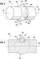
- the FIG. 2 shows an assembly 100 with a shaft 48 - for example, the drive shaft 48 of FIG. 1 - with the geometric basic shape of a cylinder.
- a hub 102 belonging to the assembly 100 is only in FIG. 5 shown.
- the shaft 48 is rotatable about the shaft axis 50 - means in the FIG. 2 not shown bearings - stored.
- the shaft 48 has a coupling portion 104 with a circular axial cross-section.
- the coupling portion 104 has a cylindrical contour 48 penetrating ball contour 106 in the manner of an annular bead.
- To the coupling portion 104 are four driver portions 108, which are each formed on a driver 110, arranged radially symmetrically.
- the driver elements 110 each comprise a ball 112 and are arranged rotationally fixed relative to the coupling portion 104. In the drawing of the FIG. 2 only three of the four driver sections 108 are visible.
- FIG. 3 shows a longitudinal section of the shaft 48 along the shaft axis 50.
- a recess 114 is shown in the coupling portion 104, in which the driving element 110 formed as a ball 112 is pressed.
- the recess 114 is a blind hole, which is dimensioned such that the ball 112 projects beyond the coupling portion 104 with approximately one third of its diameter.
- the driver portion 108 is formed spherical cap.
- the driver element 110 located there is not drawn to represent the cross section of the ball contour 106 completely (dash-dotted).
- FIG. 4 shows a side view of the shaft 48 of FIG. 2 , In addition to the FIG. 2 two arrows 116 and 118 are shown, which indicate the possible degrees of freedom for an axial tolerance compensation or an angular compensation of the shaft 48.
- FIG. 5 shows the assembly 100 with the shaft 48 and the hub 102.
- the hub 102 is a rotor 120 of a G-rotor pump.
- the hub 102 has the internal geometry of an equilateral n-corner 122, where the n-corner 122 is presently a square and includes four strongly rounded corners 124.
- the four driver sections 108 or the driver elements 110 embodied as balls 112 each extend in the direction of a corner 124 of the n-corner 122.
- a radius of the corner 124 is greater than the radius of the driver element 110 engaging in the corner 124.
- the radius of the corner 124 it is also possible for the radius of the corner 124 to be smaller than the radius of the driver element 110.
- the arrangement 100 can be optimized with respect to the force-transmitting surfaces, as well as expected axial tolerances and / or angle tolerances.
- the number of corners 124, and / or the rounding of the corners 124, and / or the diameter of the balls 112, and / or the radial length of the recesses 114, and / or the diameter of the coupling portion 104 may be different from those in FIGS FIGS. 2 to 5 shown, be measured.
- the shaft 48 rotates about the shaft axis 50. In this case, the shaft 48 transmits a torque to the hub 102.
- the present four balls 112 are preferably standard commercial parts.
- driver elements 110 are arranged radially symmetrically. Furthermore, it is possible to make the inner geometry of the hub 102 in place of a square as an equilateral triangle, pentagon and so on. This results in additional possibilities for matching the size of the permanently transmissible torque on the one hand and possible tolerances on the other hand.
- the arrangement 100 of the FIGS. 2 to 5 requires little or no additional space. As a result, the arrangement 100 can be used in a particularly versatile manner.
Landscapes
- Engineering & Computer Science (AREA)
- General Engineering & Computer Science (AREA)
- Mechanical Engineering (AREA)
- Chemical & Material Sciences (AREA)
- Combustion & Propulsion (AREA)
- Details And Applications Of Rotary Liquid Pumps (AREA)
- Gears, Cams (AREA)
- Gear Transmission (AREA)
- Shafts, Cranks, Connecting Bars, And Related Bearings (AREA)
Description
- Die Erfindung betrifft eine Zahnrad-Kraftstoffpumpe mit einer Welle und einem Zahnrad mit einer Nabe, wobei das Zahnrad mit der Welle mittels einer Anordnung verbunden ist
- Vom Markt her bekannt sind Anordnungen zur Übertragung eines Drehmoments zwischen einer Welle und einer Nabe in einer Vielzahl von Ausführungen, etwa für Zahnradpumpen. Beispielsweise weisen solche Anordnungen einen oder mehrere Passstifte auf. Sofern die Welle und die Nabe dadurch in allen Raumrichtungen starr miteinander verbunden sind, kann zwar ein vergleichsweise hohes Drehmoment übertragen werden, jedoch können Toleranzen zwischen dem Antrieb und dem Abtrieb damit nicht ausgeglichen werden. Ist in anderen Ausführungen der Übergang von der Welle auf die Nabe mit einem Spiel behaftet, so können beispielsweise geringe Winkelfehler zwischen der Welle und der Nabe ausgeglichen werden, jedoch müssen dabei im Allgemeinen beträchtliche Koaxialitätsfehler in Kauf genommen werden.
- Ferner sind entsprechende Anordnungen aus der
US 2006/240896 A1 und derJP 6 337018 A - Ferner ist ebenso die
FR952194 - Das der Erfindung zugrunde liegende Problem wird durch eine Zahnrad-Kraftstoffpumpe nach Anspruch 1 gelöst. Vorteilhafte Weiterbildungen sind in Unteransprüchen angegeben. Für die Erfindung wichtige Merkmale finden sich ferner in der nachfolgenden Beschreibung und in den Zeichnungen, wobei die Merkmale sowohl in Alleinstellung als auch in unterschiedlichen Kombinationen für die Erfindung wichtig sein können, ohne dass hierauf nochmals explizit hingewiesen wird.
- Die erfindungsgemäße Anordnung hat den Vorteil, dass ein Drehmoment zwischen einer Welle und einer Nabe übertragen werden kann, wobei die Nabe präzise auf der Welle zentriert und Winkelfehler zwischen der Welle und der Nabe ausgeglichen werden können. Dies ist beispielsweise vorteilhaft, wenn die Nabe ein Zahnrad umfasst bzw. ein Zahnrad ist, insbesondere bei einer Anwendung in einer Kraftstoff-Zahnradpumpe. Weiterhin ist ein axialer Ausgleich zwischen der Welle und der Nabe möglich. Die erfindungsgemäße Anordnung benötigt wenig Bauraum, und ist einfach und kostengünstig unter Verwendung von Normteilen herstellbar.
- Die erfindungsgemäße Nabe weist wenigstens in etwa die Innengeometrie eines gleichseitigen n-Ecks auf. Dazu passend weist die Welle einen Kupplungsabschnitt mit einem im Wesentlichen kreisförmigen Querschnitt auf. Auf dem Kupplungsabschnitt ist mindestens ein Mitnehmerabschnitt drehfest angeordnet, der sich in Richtung einer Ecke des n-Ecks der Nabe erstreckt. Vorzugsweise, jedoch nicht zwingend, ist die Zahl der Mitnehmerabschnitte größer als Eins, so dass die Anordnung radialsymmetrisch ausgeführt sein kann.
- Die Anordnung wird erfindungsgemäß verbessert, indem der Mitnehmerabschnitt kugelkappenförmig ist. Dadurch können auf einfache Weise Punktlasten oder Kerbwirkungen verkleinert oder sogar verhindert werden, und die Dauerfestigkeit der Anordnung erhöht werden.
- Erfindungsgemäß ist vorgesehen, dass der Mitnehmerabschnitt an einem Mitnehmerelement gebildet ist, das in einer Ausnehmung im Kupplungsabschnitt der Welle aufgenommen ist. Durch die Verwendung eines Mitnehmerelements, welches über eine Oberfläche des Kupplungsabschnitts hinausragt, können der Kupplungsabschnitt und das mindestens eine Mitnehmerelement besonders einfach und kostengünstig hergestellt werden. Die Ausnehmung ist beispielsweise eine radiale Bohrung oder eine Nut in dem Kupplungsabschnitt.
- Ergänzend dazu ist optional vorgesehen, dass das Mitnehmerelement in die Ausnehmung eingepresst ist. Damit kann die Anordnung einfach, kostengünstig und zugleich robust hergestellt werden,
- Eine weitere vereinfachte Herstellung der Anordnung ergibt sich, wenn das Mitnehmerelement eine Kugel umfasst. Dadurch kann beispielsweise eine handelsübliche Stahl-Kugel für das Mitnehmerelement verwendet werden, wobei die Kugel vorzugsweise mit mehr als der Hälfte ihres Volumens in dem Kupplungsabschnitt angeordnet ist, also beispielsweise darin eingepresst oder verstemmt ist.
- Die Anordnung wird weiter verbessert, wenn die Ausnehmung ein Sackloch und so dimensioniert ist, dass die Kugel mit ungefähr einem Drittel ihres Durchmessers über den Kupplungsabschnitt übersteht. Dadurch ist die Kugel genügend fest in dem Kupplungsabschnitt verankert, und steht zugleich genügend über, um das Drehmoment zu übertragen.
- Eine weitere Ausgestaltung der Erfindung sieht vor, dass die Anordnung für jedes Eck des n-Ecks mindestens einen Mitnehmerabschnitt aufweist. Dadurch werden die Möglichkeiten der Anordnung maximiert, indem das Drehmoment über alle Ecken der Nabe übertragen wird, und somit eine sich ergebende Flächenpressung in der Summe minimiert werden kann. Somit wird die Dauerfestigkeit der Anordnung weiter verbessert.
- Eine nochmals weitere Ausgestaltung der Erfindung sieht vor, dass der Kupplungsabschnitt eine umlaufende Erhebung in der Art eines Ringwulstes umfasst. Dadurch können die Mitnehmerabschnitte vergleichsweise weit über den Durchmesser der Welle hinausragen, wodurch die Möglichkeit zum Ausgleich von Toleranzen zwischen der Welle und der Nabe bzw. zwischen deren Drehachsen erhöht wird. Außerdem können so Winkelfehler besonders gut toleriert werden.
- Die Möglichkeiten der Anordnung werden erweitert, wenn der Wulst eine wenigstens in etwa kreissegmentförmige Querschnittskontur aufweist, insbesondere, wenn er durch eine die zylindrische Welle durchdringende Kugelkontur gebildet wird. Damit können eventuelle Winkel-Toleranzen besonders gut ausgeglichen werden, wobei die Flächenpressung zwischen den Mitnehmerabschnitten und der Welle und/oder lokale Materialspannungen in übrigen Bereichen der Anordnung minimiert werden.
- An Zahnrad-Kraftstoffpumpen werden im Allgemeinen vergleichsweise hohe Anforderungen in Bezug auf die Dichtheit und die Dauerfestigkeit gestellt. Außerdem sind Zahnrad-Kraftstoffpumpen häufig als separate Vorrichtungen ausgeführt, die beispielsweise auf eine aus einem Maschinengehäuse oder Motorgehäuse austretende Welle aufgesetzt werden. Eventuelle axiale und/oder Winkel-Toleranzen können durch die erfindungsgemäße Anordnung besonders gut ausgeglichen werden.
- Nachfolgend werden beispielhafte Ausführungsformen der Erfindung unter Bezugnahme auf die Zeichnung erläutert. In der Zeichnung zeigen:
- Figur 1
- ein Schema eines Kraftstoff-Einspritzsystems einer Brennkraftmaschine mit einer Zahnrad-Kraftstoffpumpe;
- Figur 2
- eine perspektivische Ansicht einer Welle der Zahnrad-Kraftstoffpumpe von
Figur 1 mit einem Kupplungsabschnitt; - Figur 3
- einen Längsschnitt durch die Welle nach
Figur 2 ; - Figur 4
- eine Seitenansicht der Welle von
Figur 2 ; und - Figur 5
- eine axiale Ansicht der Welle von
Figur 2 zusammen mit einer schematischen Darstellung einer Nabe. - Es werden für funktionsäquivalente Elemente und Größen in allen Figuren auch bei unterschiedlichen Ausführungsformen die gleichen Bezugszeichen verwendet.
- Ein in der
Figur 1 insgesamt mit dem Bezugszeichen 10 bezeichnetes Kraftstoff-Einspritzsystem zur Versorgung einer Brennkraftmaschine 12 mit Kraftstoff umfasst eine Außenzahnradpumpe 14. - Das Kraftstoff-Einspritzsystem 10 weist einen Vorratsbehälter 16 zur Bevorratung von Kraftstoff auf. Mit Hilfe einer Vorförderpumpe 18, welche vorzugsweise mittels einer regelbaren Antriebseinrichtung insbesondere in Form eines Elektromotors 20 angetrieben ist, wird Kraftstoff aus dem Vorratsbehälter 16 in eine Niederdruckleitung 22 gefördert. Durch die Verwendung einer regelbaren Antriebseinrichtung für die Vorförderpumpe 18 kann die Fördermenge des Kraftstoff-Einspritzsystems 10 verstellt werden, so dass Förderverluste reduziert werden können, die sich durch Förderung einer Überschussmenge von Kraftstoff ergibt, welcher dann wieder in den Vorratsbehälter 16 rückgeführt werden muss.
- Zur Begrenzung des Kraftstoffdrucks in der Niederdruckleitung 22 ist ein Niederdruckbegrenzungsventil 24 vorgesehen, mittels welchem bei Überschreiten eines vorgebbaren Maximaldrucks Kraftstoff aus der Niederdruckleitung 22 zurück in den Vorratsbehälter 16 geführt wird.
- Die Niederdruckleitung 22 mündet an einem Eingang 26 der Außenzahnradpumpe 14. Diese beaufschlagt den über den Eingang 26 zugeführten Kraftstoff mit Hochdruck. Der mit Hochdruck beaufschlagte Kraftstoff gelangt über einen Ausgang 28 der Außenzahnradpumpe 14 zu einer Hochdruckleitung 30, welche zu einer Kraftstoffsammeleinrichtung in Form eines Rails 32 führt. Das Rail 32 versorgt Einspritzventile 34 mit druckbeaufschlagtem Kraftstoff. Die Einspritzventile 34 sind jeweils einem der Brennräume der Brennkraftmaschine 12 zugeordnet und ermöglichen eine direkte Einspritzung des Kraftstoffs in die Brennräume.
- Der Druck in dem Rail 32 wird mit Hilfe eines Drucksensors 36 erfasst. Ein dem erfassten Druck entsprechendes Spannungssignal kann mit Hilfe einer Datenleitung 38 einem Steuergerät 40 zugeführt werden. Das Steuergerät 40 ist mittels einer Steuerleitung 42 mit dem Elektromotor 20 gekoppelt.
- Die Brennkraftmaschine 12 umfasst ein abschnittsweise dargestelltes Brennkraftmaschinengehäuse 44, beispielsweise in Form eines Zylinderkopfs. Das Brennkraftmaschinengehäuse 44 weist eine nach außen weisende Gehäuseoberfläche 46 auf. Ferner umfasst die Brennkraftmaschine 12 eine Welle, insbesondere in Form einer Nockenwelle, welche um eine Wellenachse 50 drehbar an dem Brennkraftmaschinengehäuse 44 gelagert ist und eine Antriebswelle 48 für die Außenzahnradpumpe 14 bildet. Alternativ hierzu kann die Antriebswelle 48 durch eine von einer Welle der Brennkraftmaschine 12 separate Welle gebildet sein.
- In dem Brennkraftmaschinengehäuse 44 ist eine Gehäuseöffnung 52 vorgesehen, welche von der Antriebswelle 48 durchsetzt ist, so dass ein Wellenende 54 sich über die Gehäuseoberfläche 46 hinaus in die Umgebung der Brennkraftmaschine 12 erstreckt.
- Die Außenzahnradpumpe 14 weist ein topfförmiges Außengehäuse 56 auf, welches insbesondere mit Hilfe eines angeschweißten Flansches 58 mit dem Brennkraftmaschinengehäuse 44 verbunden ist, beispielsweise mittels einer Schraubverbindung. Das Außengehäuse 56 weist einen sich in Richtung auf die Brennkraftmaschine 12 erstreckenden Gehäusevorsprung 60 auf, welcher in die Gehäuseöffnung 52 der Brennkraftmaschine 12 eingesetzt ist. Der Gehäusevorsprung 60 weist eine im Querschnitt kreisförmige Gehäuseaussparung 62 auf, welche einen Durchtritt der Antriebswelle 48 ermöglicht.
- Das Außengehäuse 56 der Außenzahnradpumpe 14 und das Brennkraftmaschinengehäuse 44 sind mit Hilfe einer ringförmigen Dichtung 64 gegeneinander abgedichtet.
- In dem Außengehäuse 56 sind mehrere Gehäuseteile angeordnet, nämlich ein erstes Gehäuseteil 66, ein hierzu beabstandetes zweites Gehäuseteil 68 sowie ein als Gehäusedeckel wirkendes drittes Gehäuseteil 70. Das dritte Gehäuseteil 70 ist mit dem Außengehäuse 56 verschweißt. Bevorzugt ist es, wenn die Gehäuseteile 66, 68 und 70 zueinander parallele Planflächen aufweisen, so dass die Gehäuseteile mit diesen Planflächen metallische Dichtflächen bilden. Dabei kann mit Hilfe des dritten Gehäuseteils 70 eine Dichtkraft erzeugt werden, welche die Gehäuseteile 66 und 68 in das Außengehäuse 56 hineindrückt.
- In axialer Richtung zwischen dem ersten Gehäuseteil 66 und dem zweiten Gehäuseteil 68 ist ein Gehäusering 72 angeordnet, in welchem eine Zahnradanordnung 74 angeordnet ist. Die Zahnradanordnung 74 bildet die eigentliche Fördereinheit der Außenzahnradpumpe 14. Die Zahnradanordnung 74 ist in axialer Richtung zwischen dem ersten Gehäuseteil 66 und dem zweiten Gehäuseteil 68 gelagert. Der Gehäusering 72 dient zur radialen Lagerung der Zahnradanordnung 74.
- Die Außenzahnradpumpe 14 weist niederdruckseitig einen mit dem Eingang 26 verbundenen Niederdruckkanal 76 auf, welcher in dem dritten Gehäuseteil 70 ausgebildet ist. Der Niederdruckkanal 76 mündet an einer Saugniere 78, welche in dem zweiten Gehäuseteil 68 ausgebildet ist. Das erste Gehäuseteil 66 weist eine der Form der Saugniere 78 entsprechende Gegenniere 80 auf.
- Druckseitig umfasst die Außenzahnradpumpe 14 einen mit dem Ausgang 28 verbundenen Hochdruckkanal 82 auf, welcher in dem dritten Gehäuseteil 70 ausgebildet ist. Der Hochdruckkanal 82 ist mit einer Druckniere 84 verbunden, welche in dem zweiten Gehäuseteil 68 ausgebildet ist. In dem ersten Gehäuseteil 66 ist eine der Form der Druckniere 84 entsprechende Gegenniere 86 angeordnet. Mit Hilfe der Gegennieren 80 und 86 wird erreicht, dass die Zahnradanordnung 74 von beiden Seiten her gleichmäßig mit Druck belastet wird.
- Ferner umfasst die Außenzahnradpumpe 14 ein Druckbegrenzungsventil 88, mittels welchem bei Überschreiten eines vorgebbaren Betriebsdrucks eine Fluidverbindung zwischen dem Hochdruckkanal 82 und dem Niederdruckkanal 76 herstellbar ist. Das Druckbegrenzungsventil 88 ist in einem Verbindungskanal 90 angeordnet, welcher sich zwischen dem Hochdruckkanal 82 und dem Niederdruckkanal 76 erstreckt. Das Druckbegrenzungsventil 88 weist eine in den Verbindungskanal 90 eingepressten Ventilsitz, einen mit dem Ventilsitz zusammenwirkenden Ventilkörper und eine Ventilfeder auf, welche den Ventilkörper gegen den Ventilsitz drückt. Der Ventilsitz, der Ventilkörper und die Ventilfeder sind in der Zeichnung der
Figur 1 ohne Bezugszeichen dargestellt. - Der Verbindungskanal 90 ist in Form einer Sacklochbohrung ausgebildet und an dessen offenem Ende mit Hilfe eines eingepressten Stopfens 98 verschlossen.
- Die Integration des Eingangs 26 und des Ausgangs 28 sowie des Druckbegrenzungsventils 88 in das dritte Gehäuseteil 70 ermöglicht einen weitgehenden Verzicht auf zusätzliche Dichtelemente und somit eine weitere Verringerung der Bauteilzahl der Außenzahnradpumpe 14.
- Die in der
Figur 1 beschriebene Außenzahnradpumpe 14 weist eine WellenNaben-Verbindung ähnlich den nachfolgendenFiguren 2 bis 5 auf. - Die
Figur 2 zeigt eine Anordnung 100 mit einer Welle 48 - beispielsweise die Antriebswelle 48 derFigur 1 - mit der geometrischen Grundform eines Zylinders. Eine zu der Anordnung 100 gehörende Nabe 102 ist nur inFigur 5 dargestellt. Die Welle 48 ist um die Wellenachse 50 drehbar - mittels in derFigur 2 nicht gezeigten Lagern - gelagert. In einem mittleren Bereich der Zeichnung weist die Welle 48 einen Kupplungsabschnitt 104 mit einem kreisförmigen axialen Querschnitt auf. Vorliegend weist der Kupplungsabschnitt 104 eine die zylindrische Welle 48 durchdringende Kugelkontur 106 in der Art eines Ringwulstes auf. Um den Kupplungsabschnitt 104 sind vier Mitnehmerabschnitte 108, welche jeweils an einem Mitnehmerelement 110 gebildet sind, radialsymmetrisch angeordnet. Die Mitnehmerelemente 110 umfassen jeweils eine Kugel 112 und sind relativ zu dem Kupplungsabschnitt 104 drehfest angeordnet. In der Zeichnung derFigur 2 sind nur drei der vier Mitnehmerabschnitte 108 sichtbar. - Die
Figur 3 zeigt einen Längsschnitt der Welle 48 entlang der Wellenachse 50. Im oberen Bereich der Zeichnung vonFigur 3 ist eine Ausnehmung 114 in dem Kupplungsabschnitt 104 dargestellt, in den das als Kugel 112 ausgebildete Mitnehmerelement 110 eingepresst ist. Vorliegend ist die Ausnehmung 114 ein Sackloch, welches so dimensioniert ist, dass die Kugel 112 mit ungefähr einem Drittel ihres Durchmessers über den Kupplungsabschnitt 104 übersteht. Dadurch ist der Mitnehmerabschnitt 108 kugelkappenförmig ausgebildet. Im unteren Bereich der Zeichnung vonFigur 3 ist das dort befindliche Mitnehmerelement 110 nicht mit gezeichnet, um den Querschnitt der Kugelkontur 106 vollständig (strichpunktiert) darzustellen. - Die
Figur 4 zeigt eine seitliche Ansicht der Welle 48 vonFigur 2 . Ergänzend zu derFigur 2 sind zwei Pfeile 116 und 118 eingezeichnet, welche die möglichen Freiheitsgrade für einen axialen Toleranzausgleich bzw. einen Winkelausgleich der Welle 48 kenntlich machen. - Die
Figur 5 zeigt die Anordnung 100 mit der Welle 48 und der Nabe 102. Vorliegend ist die Nabe 102 ein Rotor 120 einer G-Rotorpumpe. Die Nabe 102 weist die Innengeometrie eines gleichseitigen n-Ecks 122 auf, wobei das n-Eck 122 vorliegend ein Quadrat ist und vier stark abgerundete Ecken 124 umfasst. - Man erkennt, dass die vier Seitenflächen des n-Ecks 122 an dem Kupplungsabschnitt 104 in etwa anliegen. Dies ist in der Zeichnung durch einen Pfeil 126 dargestellt. Dadurch wird die Nabe 102 auf der Welle 48 zentriert, wobei zugleich eine Kippbewegung zwischen der Welle 48 und der Nabe 102 um einen - von der konkreten Ausführung abhängigen - Winkel zulässig ist.
- Weiterhin ist zu erkennen, dass die vier Mitnehmerabschnitte 108 bzw. die als Kugeln 112 ausgebildeten Mitnehmerelemente 110 sich jeweils in Richtung einer Ecke 124 des n-Ecks 122 erstrecken. Dabei ist vorliegend ein Radius der Ecke 124 größer als der Radius des in die Ecke 124 eingreifenden Mitnehmerelements 110. Es ist jedoch ebenso möglich, dass der Radius der Ecke 124 kleiner ist als der Radius des Mitnehmerelements 110.
- Durch eine passende Dimensionierung des Kupplungsabschnitts 104 und der Innengeometrie des n-Ecks 122 und der sich jeweils ergebenden Freiheitsgrade kann die Anordnung 100 in Bezug auf die kraftübertragenden Flächen, sowie auf zu erwartende axiale Toleranzen und/oder auf Winkel-Toleranzen optimiert sein. Dazu können beispielsweise die Zahl der Ecken 124, und/oder die Abrundung der Ecken 124, und/oder der Durchmesser der Kugeln 112, und/oder die radiale Länge der Ausnehmungen 114, und/oder der Durchmesser des Kupplungsabschnitts 104, anders als in den
Figuren 2 bis 5 dargestellt, bemessen sein. - Im Betrieb dreht sich die Welle 48 um die Wellenachse 50. Dabei überträgt die Welle 48 ein Drehmoment auf die Nabe 102. Die vorliegend vier Kugeln 112 sind vorzugsweise handelsübliche Normteile.
- Es ist möglich, die Übertragung des Drehmoments zwischen der Welle 48 und der Nabe 102 auch nur mit dreien, zweien oder sogar nur mit einem Mitnehmerelement 110 auszuführen. Vorzugsweise sind die Mitnehmerelemente 110 radialsymmetrisch angeordnet. Weiterhin ist es möglich, die Innengeometrie der Nabe 102 an Stelle eines Quadrats auch als gleichseitiges Dreieck, Fünfeck und so weiter auszuführen. Dadurch ergeben sich zusätzliche Möglichkeiten, um die Größe des dauerfest übertragbaren Drehmoments einerseits und eventuelle Toleranzen andererseits, aufeinander abzustimmen.
- Weiterhin ist zu erkennen, dass die Anordnung 100 der
Figuren 2 bis 5 wenig oder keinen zusätzlichen Bauraum erfordert. Dadurch kann die Anordnung 100 besonders vielseitig verwendet werden.
Claims (7)
- Zahnrad-Kraftstoffpumpe (14), mit einer Welle (48) und einem Zahnrad mit einer Nabe (102), wobei das Zahnrad mit der Welle (48) mittels folgender Anordnung (100) verbunden ist:Anordnung (100) zur Übertragung eines Drehmoments zwischen der Welle (48) und der Nabe (102), wobei die Nabe (102) wenigstens in etwa die Innengeometrie eines gleichseitigen n-Ecks (122) aufweist, dessen Seitenflächen an einem im Querschnitt insgesamt kreisförmigen Kupplungsabschnitt (104) der Welle (48) wenigstens in etwa anliegen, unddass die Welle mindestens einen Mitnehmerabschnitt (108) aufweist, der relativ zum Kupplungsabschnitt (104) drehfest ist und sich in Richtung einer Ecke (124) des n-Eckes (122) erstreckt, wobei der Mitnehmerabschnitt (108) kugelkappenförmig ist und wobei der Mitnehmerabschnitt (108) an einem Mitnehmerelement (110) gebildet ist, das in einer Ausnehmung (114) im Kupplungsabschnitt (104) der Welle (48) aufgenommen ist und wobei ein Radius der Ecke (124) größer oder kleiner ist als der Radius des in die Ecke (124) eingreifenden Mitnehmerelements (110).
- Zahnrad-Kraftstoffpumpe (14) nach Anspruch 1, dadurch gekennzeichnet, dass das Mitnehmerelement (110) in die Ausnehmung (114) eingepresst ist.
- Zahnrad-Kraftstoffpumpe (14) nach einem der Ansprüche 1 oder 2, dadurch gekennzeichnet, dass das Mitnehmerelement (110) eine Kugel (112) umfasst.
- Zahnrad-Kraftstoffpumpe (14) nach Anspruch 3, dadurch gekennzeichnet, dass die Ausnehmung (114) ein Sackloch und so dimensioniert ist, dass die Kugel (112) mit ungefähr einem Drittel ihres Durchmessers über den Kupplungsabschnitt (104) übersteht.
- Zahnrad-Kraftstoffpumpe (14) nach einem der vorhergehenden Ansprüche, dadurch gekennzeichnet, dass sie für jedes Eck (124) des n-Ecks (122) mindestens einen Mitnehmerabschnitt (108) aufweist.
- Zahnrad-Kraftstoffpumpe (14) nach einem der vorhergehenden Ansprüche, dadurch gekennzeichnet, dass der Kupplungsabschnitt (104) eine umlaufende Erhebung in der Art eines Ringwulstes umfasst.
- Zahnrad-Kraftstoffpumpe (14) nach Anspruch 6, dadurch gekennzeichnet, dass der Wulst eine wenigstens in etwa kreissegmentförmige Querschnittskontur aufweist, insbesondere, dass er durch eine die zylindrische Welle (48) durchdringende Kugelkontur (106) gebildet wird.
Applications Claiming Priority (2)
| Application Number | Priority Date | Filing Date | Title |
|---|---|---|---|
| DE102010043118A DE102010043118A1 (de) | 2010-10-29 | 2010-10-29 | Anordnung zur Übertragung eines Drehmoments zwischen einer Welle und einer Nabe |
| PCT/EP2011/064872 WO2012055611A1 (de) | 2010-10-29 | 2011-08-30 | Anordnung zur übertragung eines drehmoments zwischen einer welle und einer nabe |
Publications (2)
| Publication Number | Publication Date |
|---|---|
| EP2633203A1 EP2633203A1 (de) | 2013-09-04 |
| EP2633203B1 true EP2633203B1 (de) | 2019-03-20 |
Family
ID=44545724
Family Applications (1)
| Application Number | Title | Priority Date | Filing Date |
|---|---|---|---|
| EP11751880.3A Not-in-force EP2633203B1 (de) | 2010-10-29 | 2011-08-30 | Zahnrad-Kraftstoffpumpe mit einer Anordnung zur Übertragung eines Drehmoments zwischen einer Welle und einer Nabe |
Country Status (5)
| Country | Link |
|---|---|
| US (1) | US9039539B2 (de) |
| EP (1) | EP2633203B1 (de) |
| CN (1) | CN103180628B (de) |
| DE (1) | DE102010043118A1 (de) |
| WO (1) | WO2012055611A1 (de) |
Families Citing this family (8)
| Publication number | Priority date | Publication date | Assignee | Title |
|---|---|---|---|---|
| BR102012030914B1 (pt) | 2012-12-04 | 2015-12-22 | Ademar Birck | eixo bipartido, conjunto eixo-cubo e uso dos mesmos |
| DE102013216516B4 (de) * | 2013-08-21 | 2024-09-19 | Robert Bosch Gmbh | Handwerkzeugmaschinenwerkzeugaufnahme |
| CN103776590B (zh) * | 2014-02-26 | 2016-11-23 | 成都卓微科技有限公司 | 一种转子平衡实验台 |
| CA3085668A1 (en) * | 2017-12-13 | 2019-06-20 | Exponential Technologies, Inc. | Rotary fluid flow device |
| ES3000811T3 (en) * | 2018-04-06 | 2025-03-03 | Entecnia Consulting S L U | Rotary pump |
| US11168683B2 (en) | 2019-03-14 | 2021-11-09 | Exponential Technologies, Inc. | Pressure balancing system for a fluid pump |
| DE102020133212A1 (de) | 2020-12-11 | 2022-06-15 | Nidec Gpm Gmbh | Welle-Nabe-Verbindung und Fluidpumpe aufweisend die Welle-Nabe-Verbindung |
| CN115750750A (zh) * | 2022-09-23 | 2023-03-07 | 福建万润新能源科技有限公司 | 一种带有强制润滑的行星减速器、起重机及车辆 |
Family Cites Families (9)
| Publication number | Priority date | Publication date | Assignee | Title |
|---|---|---|---|---|
| DE663625C (de) * | 1936-07-24 | 1938-08-10 | Anton Penzenleitner | Gelenkkupplung, insbesondere beim Antrieb der Walzen von Walzwerken |
| DE678093C (de) * | 1937-04-01 | 1939-07-08 | Anton Penzenleitner | Gelenkkupplung zur zwangslaeufigen UEbertragung von Drehkraeften bei Antrieben aller Art, insbesondere fuer Walzwerksantriebe |
| BE476450A (de) * | 1947-04-25 | |||
| FR2496792A2 (fr) * | 1976-07-31 | 1982-06-25 | Uni Cardan Ag | Joint universel pour arbre articule |
| DE3048339C2 (de) * | 1980-12-20 | 1983-12-22 | Uni-Cardan Ag, 5200 Siegburg | Winkelbewegliche Gelenkkupplung |
| JPH06337018A (ja) * | 1993-05-27 | 1994-12-06 | Daishin Seisakusho:Kk | シャフト継手 |
| US5738586A (en) * | 1994-09-09 | 1998-04-14 | Consolidated Devices Inc. | Semi-universal torque coupling |
| JP2002040875A (ja) | 2000-07-24 | 2002-02-06 | Canon Inc | プロセスカートリッジ |
| CN1851282B (zh) | 2005-04-21 | 2012-06-27 | Ntn株式会社 | 等速联轴器及图像形成装置 |
-
2010
- 2010-10-29 DE DE102010043118A patent/DE102010043118A1/de not_active Withdrawn
-
2011
- 2011-08-30 CN CN201180051796.8A patent/CN103180628B/zh not_active Expired - Fee Related
- 2011-08-30 US US13/881,691 patent/US9039539B2/en not_active Expired - Fee Related
- 2011-08-30 WO PCT/EP2011/064872 patent/WO2012055611A1/de not_active Ceased
- 2011-08-30 EP EP11751880.3A patent/EP2633203B1/de not_active Not-in-force
Non-Patent Citations (1)
| Title |
|---|
| None * |
Also Published As
| Publication number | Publication date |
|---|---|
| US20130281220A1 (en) | 2013-10-24 |
| CN103180628B (zh) | 2016-03-16 |
| US9039539B2 (en) | 2015-05-26 |
| DE102010043118A1 (de) | 2012-05-03 |
| CN103180628A (zh) | 2013-06-26 |
| WO2012055611A1 (de) | 2012-05-03 |
| EP2633203A1 (de) | 2013-09-04 |
Similar Documents
| Publication | Publication Date | Title |
|---|---|---|
| EP2633203A1 (de) | Anordnung zur übertragung eines drehmoments zwischen einer welle und einer nabe | |
| EP1305523B1 (de) | Innenzahnradpumpe | |
| WO2017041802A1 (de) | Getriebe mit elastischem zahnrad | |
| EP2409014B1 (de) | HOCHDRUCKPUMPE UND STÖßELBAUGRUPPE | |
| EP2299071B1 (de) | Vorrichtung zur Veränderung einer relativen Drehwinkellage einer Nockenwelle gegenüber einer Kurbelwelle einer Brennkraftmaschine | |
| DE3912965A1 (de) | Aggregat zum foerdern von kraftstoff | |
| EP3827170A1 (de) | Fluidfördereinrichtung | |
| EP2569525A1 (de) | Vorrichtung zum antrieb eines nebenaggregates | |
| EP2252795B1 (de) | Brennstoffpumpe | |
| DE10058012A1 (de) | Zahnradförderpumpe, insbesondere zum Fördern von Kraftstoff zu einer Kraftstoffhochdruckpumpe | |
| EP2510239A2 (de) | AUßENZAHNRADPUMPE | |
| EP2379891A2 (de) | Innenzahnradpumpe | |
| DE102009047709A1 (de) | Zahnradpumpe | |
| EP2207958B1 (de) | Radialkolbenpumpe mit einem prismatischen grundkörper für ein kraftstoffeinspritzsystem | |
| EP3361069B1 (de) | Pleuel einer brennkraftmaschine mit variabler verdichtung mit einem rückschlagventil | |
| EP2619464A1 (de) | Spannstift | |
| DE102011082644A1 (de) | Pumpenanordnung für ein Kraftstoffeinspritzsystem sowie Kraftstoffeinspritzsystem | |
| DE102015210798B4 (de) | Kraftstoffhochdruckpumpe | |
| DE20109650U1 (de) | Elektromechanisch angetriebene Doppelmembranpumpe | |
| EP1906020B1 (de) | Flüssigkeitspumpe mit regelbarem Fördervolumen | |
| WO2018229243A1 (de) | Pumpenanordnung und verfahren zur herstellung einer pumpenanordnung | |
| WO2017202711A1 (de) | System aus einer nockenwelle und einer nockenwellenhülse | |
| WO2017055103A1 (de) | Hochdruckpumpe | |
| WO2017186497A1 (de) | Exzenterschneckenpumpe | |
| DE102011122027B3 (de) | Hydrostatischer Kreiskolbenmotor |
Legal Events
| Date | Code | Title | Description |
|---|---|---|---|
| PUAI | Public reference made under article 153(3) epc to a published international application that has entered the european phase |
Free format text: ORIGINAL CODE: 0009012 |
|
| 17P | Request for examination filed |
Effective date: 20130529 |
|
| AK | Designated contracting states |
Kind code of ref document: A1 Designated state(s): AL AT BE BG CH CY CZ DE DK EE ES FI FR GB GR HR HU IE IS IT LI LT LU LV MC MK MT NL NO PL PT RO RS SE SI SK SM TR |
|
| DAX | Request for extension of the european patent (deleted) | ||
| STAA | Information on the status of an ep patent application or granted ep patent |
Free format text: STATUS: EXAMINATION IS IN PROGRESS |
|
| 17Q | First examination report despatched |
Effective date: 20170721 |
|
| REG | Reference to a national code |
Ref country code: DE Ref legal event code: R079 Ref document number: 502011015512 Country of ref document: DE Free format text: PREVIOUS MAIN CLASS: F16D0003180000 Ipc: F02M0037040000 |
|
| GRAP | Despatch of communication of intention to grant a patent |
Free format text: ORIGINAL CODE: EPIDOSNIGR1 |
|
| RIC1 | Information provided on ipc code assigned before grant |
Ipc: F02M 37/04 20060101AFI20181018BHEP |
|
| STAA | Information on the status of an ep patent application or granted ep patent |
Free format text: STATUS: GRANT OF PATENT IS INTENDED |
|
| INTG | Intention to grant announced |
Effective date: 20181122 |
|
| GRAS | Grant fee paid |
Free format text: ORIGINAL CODE: EPIDOSNIGR3 |
|
| GRAA | (expected) grant |
Free format text: ORIGINAL CODE: 0009210 |
|
| STAA | Information on the status of an ep patent application or granted ep patent |
Free format text: STATUS: THE PATENT HAS BEEN GRANTED |
|
| AK | Designated contracting states |
Kind code of ref document: B1 Designated state(s): AL AT BE BG CH CY CZ DE DK EE ES FI FR GB GR HR HU IE IS IT LI LT LU LV MC MK MT NL NO PL PT RO RS SE SI SK SM TR |
|
| REG | Reference to a national code |
Ref country code: GB Ref legal event code: FG4D Free format text: NOT ENGLISH |
|
| REG | Reference to a national code |
Ref country code: CH Ref legal event code: EP |
|
| REG | Reference to a national code |
Ref country code: DE Ref legal event code: R096 Ref document number: 502011015512 Country of ref document: DE |
|
| REG | Reference to a national code |
Ref country code: AT Ref legal event code: REF Ref document number: 1110807 Country of ref document: AT Kind code of ref document: T Effective date: 20190415 |
|
| REG | Reference to a national code |
Ref country code: IE Ref legal event code: FG4D Free format text: LANGUAGE OF EP DOCUMENT: GERMAN |
|
| REG | Reference to a national code |
Ref country code: NL Ref legal event code: MP Effective date: 20190320 |
|
| PG25 | Lapsed in a contracting state [announced via postgrant information from national office to epo] |
Ref country code: SE Free format text: LAPSE BECAUSE OF FAILURE TO SUBMIT A TRANSLATION OF THE DESCRIPTION OR TO PAY THE FEE WITHIN THE PRESCRIBED TIME-LIMIT Effective date: 20190320 Ref country code: LT Free format text: LAPSE BECAUSE OF FAILURE TO SUBMIT A TRANSLATION OF THE DESCRIPTION OR TO PAY THE FEE WITHIN THE PRESCRIBED TIME-LIMIT Effective date: 20190320 Ref country code: FI Free format text: LAPSE BECAUSE OF FAILURE TO SUBMIT A TRANSLATION OF THE DESCRIPTION OR TO PAY THE FEE WITHIN THE PRESCRIBED TIME-LIMIT Effective date: 20190320 Ref country code: NO Free format text: LAPSE BECAUSE OF FAILURE TO SUBMIT A TRANSLATION OF THE DESCRIPTION OR TO PAY THE FEE WITHIN THE PRESCRIBED TIME-LIMIT Effective date: 20190620 |
|
| REG | Reference to a national code |
Ref country code: LT Ref legal event code: MG4D |
|
| PG25 | Lapsed in a contracting state [announced via postgrant information from national office to epo] |
Ref country code: BG Free format text: LAPSE BECAUSE OF FAILURE TO SUBMIT A TRANSLATION OF THE DESCRIPTION OR TO PAY THE FEE WITHIN THE PRESCRIBED TIME-LIMIT Effective date: 20190620 Ref country code: HR Free format text: LAPSE BECAUSE OF FAILURE TO SUBMIT A TRANSLATION OF THE DESCRIPTION OR TO PAY THE FEE WITHIN THE PRESCRIBED TIME-LIMIT Effective date: 20190320 Ref country code: GR Free format text: LAPSE BECAUSE OF FAILURE TO SUBMIT A TRANSLATION OF THE DESCRIPTION OR TO PAY THE FEE WITHIN THE PRESCRIBED TIME-LIMIT Effective date: 20190621 Ref country code: LV Free format text: LAPSE BECAUSE OF FAILURE TO SUBMIT A TRANSLATION OF THE DESCRIPTION OR TO PAY THE FEE WITHIN THE PRESCRIBED TIME-LIMIT Effective date: 20190320 Ref country code: NL Free format text: LAPSE BECAUSE OF FAILURE TO SUBMIT A TRANSLATION OF THE DESCRIPTION OR TO PAY THE FEE WITHIN THE PRESCRIBED TIME-LIMIT Effective date: 20190320 Ref country code: RS Free format text: LAPSE BECAUSE OF FAILURE TO SUBMIT A TRANSLATION OF THE DESCRIPTION OR TO PAY THE FEE WITHIN THE PRESCRIBED TIME-LIMIT Effective date: 20190320 |
|
| PG25 | Lapsed in a contracting state [announced via postgrant information from national office to epo] |
Ref country code: CZ Free format text: LAPSE BECAUSE OF FAILURE TO SUBMIT A TRANSLATION OF THE DESCRIPTION OR TO PAY THE FEE WITHIN THE PRESCRIBED TIME-LIMIT Effective date: 20190320 Ref country code: RO Free format text: LAPSE BECAUSE OF FAILURE TO SUBMIT A TRANSLATION OF THE DESCRIPTION OR TO PAY THE FEE WITHIN THE PRESCRIBED TIME-LIMIT Effective date: 20190320 Ref country code: IT Free format text: LAPSE BECAUSE OF FAILURE TO SUBMIT A TRANSLATION OF THE DESCRIPTION OR TO PAY THE FEE WITHIN THE PRESCRIBED TIME-LIMIT Effective date: 20190320 Ref country code: SK Free format text: LAPSE BECAUSE OF FAILURE TO SUBMIT A TRANSLATION OF THE DESCRIPTION OR TO PAY THE FEE WITHIN THE PRESCRIBED TIME-LIMIT Effective date: 20190320 Ref country code: ES Free format text: LAPSE BECAUSE OF FAILURE TO SUBMIT A TRANSLATION OF THE DESCRIPTION OR TO PAY THE FEE WITHIN THE PRESCRIBED TIME-LIMIT Effective date: 20190320 Ref country code: EE Free format text: LAPSE BECAUSE OF FAILURE TO SUBMIT A TRANSLATION OF THE DESCRIPTION OR TO PAY THE FEE WITHIN THE PRESCRIBED TIME-LIMIT Effective date: 20190320 Ref country code: PT Free format text: LAPSE BECAUSE OF FAILURE TO SUBMIT A TRANSLATION OF THE DESCRIPTION OR TO PAY THE FEE WITHIN THE PRESCRIBED TIME-LIMIT Effective date: 20190720 Ref country code: AL Free format text: LAPSE BECAUSE OF FAILURE TO SUBMIT A TRANSLATION OF THE DESCRIPTION OR TO PAY THE FEE WITHIN THE PRESCRIBED TIME-LIMIT Effective date: 20190320 |
|
| PGFP | Annual fee paid to national office [announced via postgrant information from national office to epo] |
Ref country code: FR Payment date: 20190822 Year of fee payment: 9 |
|
| PG25 | Lapsed in a contracting state [announced via postgrant information from national office to epo] |
Ref country code: PL Free format text: LAPSE BECAUSE OF FAILURE TO SUBMIT A TRANSLATION OF THE DESCRIPTION OR TO PAY THE FEE WITHIN THE PRESCRIBED TIME-LIMIT Effective date: 20190320 Ref country code: SM Free format text: LAPSE BECAUSE OF FAILURE TO SUBMIT A TRANSLATION OF THE DESCRIPTION OR TO PAY THE FEE WITHIN THE PRESCRIBED TIME-LIMIT Effective date: 20190320 |
|
| PG25 | Lapsed in a contracting state [announced via postgrant information from national office to epo] |
Ref country code: IS Free format text: LAPSE BECAUSE OF FAILURE TO SUBMIT A TRANSLATION OF THE DESCRIPTION OR TO PAY THE FEE WITHIN THE PRESCRIBED TIME-LIMIT Effective date: 20190720 |
|
| REG | Reference to a national code |
Ref country code: DE Ref legal event code: R097 Ref document number: 502011015512 Country of ref document: DE |
|
| PLBE | No opposition filed within time limit |
Free format text: ORIGINAL CODE: 0009261 |
|
| STAA | Information on the status of an ep patent application or granted ep patent |
Free format text: STATUS: NO OPPOSITION FILED WITHIN TIME LIMIT |
|
| PG25 | Lapsed in a contracting state [announced via postgrant information from national office to epo] |
Ref country code: DK Free format text: LAPSE BECAUSE OF FAILURE TO SUBMIT A TRANSLATION OF THE DESCRIPTION OR TO PAY THE FEE WITHIN THE PRESCRIBED TIME-LIMIT Effective date: 20190320 |
|
| PGFP | Annual fee paid to national office [announced via postgrant information from national office to epo] |
Ref country code: DE Payment date: 20191021 Year of fee payment: 9 |
|
| 26N | No opposition filed |
Effective date: 20200102 |
|
| PG25 | Lapsed in a contracting state [announced via postgrant information from national office to epo] |
Ref country code: SI Free format text: LAPSE BECAUSE OF FAILURE TO SUBMIT A TRANSLATION OF THE DESCRIPTION OR TO PAY THE FEE WITHIN THE PRESCRIBED TIME-LIMIT Effective date: 20190320 |
|
| PG25 | Lapsed in a contracting state [announced via postgrant information from national office to epo] |
Ref country code: TR Free format text: LAPSE BECAUSE OF FAILURE TO SUBMIT A TRANSLATION OF THE DESCRIPTION OR TO PAY THE FEE WITHIN THE PRESCRIBED TIME-LIMIT Effective date: 20190320 |
|
| GBPC | Gb: european patent ceased through non-payment of renewal fee |
Effective date: 20190830 |
|
| PG25 | Lapsed in a contracting state [announced via postgrant information from national office to epo] |
Ref country code: MC Free format text: LAPSE BECAUSE OF FAILURE TO SUBMIT A TRANSLATION OF THE DESCRIPTION OR TO PAY THE FEE WITHIN THE PRESCRIBED TIME-LIMIT Effective date: 20190320 Ref country code: LI Free format text: LAPSE BECAUSE OF NON-PAYMENT OF DUE FEES Effective date: 20190831 Ref country code: LU Free format text: LAPSE BECAUSE OF NON-PAYMENT OF DUE FEES Effective date: 20190830 Ref country code: CH Free format text: LAPSE BECAUSE OF NON-PAYMENT OF DUE FEES Effective date: 20190831 |
|
| REG | Reference to a national code |
Ref country code: BE Ref legal event code: MM Effective date: 20190831 |
|
| PG25 | Lapsed in a contracting state [announced via postgrant information from national office to epo] |
Ref country code: IE Free format text: LAPSE BECAUSE OF NON-PAYMENT OF DUE FEES Effective date: 20190830 |
|
| PG25 | Lapsed in a contracting state [announced via postgrant information from national office to epo] |
Ref country code: GB Free format text: LAPSE BECAUSE OF NON-PAYMENT OF DUE FEES Effective date: 20190830 Ref country code: BE Free format text: LAPSE BECAUSE OF NON-PAYMENT OF DUE FEES Effective date: 20190831 |
|
| REG | Reference to a national code |
Ref country code: AT Ref legal event code: MM01 Ref document number: 1110807 Country of ref document: AT Kind code of ref document: T Effective date: 20190830 |
|
| PG25 | Lapsed in a contracting state [announced via postgrant information from national office to epo] |
Ref country code: AT Free format text: LAPSE BECAUSE OF NON-PAYMENT OF DUE FEES Effective date: 20190830 |
|
| REG | Reference to a national code |
Ref country code: DE Ref legal event code: R119 Ref document number: 502011015512 Country of ref document: DE |
|
| PG25 | Lapsed in a contracting state [announced via postgrant information from national office to epo] |
Ref country code: CY Free format text: LAPSE BECAUSE OF FAILURE TO SUBMIT A TRANSLATION OF THE DESCRIPTION OR TO PAY THE FEE WITHIN THE PRESCRIBED TIME-LIMIT Effective date: 20190320 |
|
| PG25 | Lapsed in a contracting state [announced via postgrant information from national office to epo] |
Ref country code: DE Free format text: LAPSE BECAUSE OF NON-PAYMENT OF DUE FEES Effective date: 20210302 Ref country code: HU Free format text: LAPSE BECAUSE OF FAILURE TO SUBMIT A TRANSLATION OF THE DESCRIPTION OR TO PAY THE FEE WITHIN THE PRESCRIBED TIME-LIMIT; INVALID AB INITIO Effective date: 20110830 Ref country code: MT Free format text: LAPSE BECAUSE OF FAILURE TO SUBMIT A TRANSLATION OF THE DESCRIPTION OR TO PAY THE FEE WITHIN THE PRESCRIBED TIME-LIMIT Effective date: 20190320 Ref country code: FR Free format text: LAPSE BECAUSE OF NON-PAYMENT OF DUE FEES Effective date: 20200831 |
|
| PG25 | Lapsed in a contracting state [announced via postgrant information from national office to epo] |
Ref country code: MK Free format text: LAPSE BECAUSE OF FAILURE TO SUBMIT A TRANSLATION OF THE DESCRIPTION OR TO PAY THE FEE WITHIN THE PRESCRIBED TIME-LIMIT Effective date: 20190320 |