EP2632067A1 - Sendeverfahren, sendervorrichtung, empfangsverfahren und empfangsvorrichtung - Google Patents
Sendeverfahren, sendervorrichtung, empfangsverfahren und empfangsvorrichtung Download PDFInfo
- Publication number
- EP2632067A1 EP2632067A1 EP11834031.4A EP11834031A EP2632067A1 EP 2632067 A1 EP2632067 A1 EP 2632067A1 EP 11834031 A EP11834031 A EP 11834031A EP 2632067 A1 EP2632067 A1 EP 2632067A1
- Authority
- EP
- European Patent Office
- Prior art keywords
- signal
- precoding
- math
- symbol
- equation
- Prior art date
- Legal status (The legal status is an assumption and is not a legal conclusion. Google has not performed a legal analysis and makes no representation as to the accuracy of the status listed.)
- Granted
Links
- 238000000034 method Methods 0.000 title claims abstract description 814
- 230000005540 biological transmission Effects 0.000 title description 516
- 239000011159 matrix material Substances 0.000 claims abstract description 292
- 238000012937 correction Methods 0.000 claims abstract description 112
- 238000012545 processing Methods 0.000 description 75
- 238000004891 communication Methods 0.000 description 55
- 238000001514 detection method Methods 0.000 description 54
- 230000000694 effects Effects 0.000 description 43
- 238000004364 calculation method Methods 0.000 description 34
- 230000008859 change Effects 0.000 description 30
- 238000006243 chemical reaction Methods 0.000 description 19
- 239000000969 carrier Substances 0.000 description 18
- 238000007476 Maximum Likelihood Methods 0.000 description 16
- 235000008694 Humulus lupulus Nutrition 0.000 description 14
- 238000013461 design Methods 0.000 description 14
- 239000002609 medium Substances 0.000 description 14
- 238000001824 photoionisation detection Methods 0.000 description 10
- 238000005516 engineering process Methods 0.000 description 9
- 238000012986 modification Methods 0.000 description 9
- 230000004048 modification Effects 0.000 description 9
- 230000015556 catabolic process Effects 0.000 description 8
- 238000006731 degradation reaction Methods 0.000 description 8
- 238000013507 mapping Methods 0.000 description 8
- 230000005236 sound signal Effects 0.000 description 8
- 101100228469 Caenorhabditis elegans exp-1 gene Proteins 0.000 description 7
- 239000000284 extract Substances 0.000 description 7
- 230000006870 function Effects 0.000 description 7
- 230000003321 amplification Effects 0.000 description 6
- 230000010354 integration Effects 0.000 description 6
- 238000003199 nucleic acid amplification method Methods 0.000 description 6
- 238000003672 processing method Methods 0.000 description 6
- 239000004065 semiconductor Substances 0.000 description 6
- 230000008901 benefit Effects 0.000 description 5
- 238000004422 calculation algorithm Methods 0.000 description 5
- 238000005562 fading Methods 0.000 description 5
- 230000004044 response Effects 0.000 description 4
- 238000012546 transfer Methods 0.000 description 4
- 239000006163 transport media Substances 0.000 description 4
- 238000004458 analytical method Methods 0.000 description 3
- 238000007906 compression Methods 0.000 description 3
- 230000006835 compression Effects 0.000 description 3
- 230000002452 interceptive effect Effects 0.000 description 3
- 230000003287 optical effect Effects 0.000 description 3
- 230000010363 phase shift Effects 0.000 description 3
- 230000008569 process Effects 0.000 description 3
- 239000000470 constituent Substances 0.000 description 2
- 125000004122 cyclic group Chemical group 0.000 description 2
- 238000010586 diagram Methods 0.000 description 2
- 238000000605 extraction Methods 0.000 description 2
- 238000009432 framing Methods 0.000 description 2
- 230000006872 improvement Effects 0.000 description 2
- 230000009467 reduction Effects 0.000 description 2
- 238000000926 separation method Methods 0.000 description 2
- 208000037146 Atypical Timothy syndrome Diseases 0.000 description 1
- 101100006960 Caenorhabditis elegans let-2 gene Proteins 0.000 description 1
- 101000582320 Homo sapiens Neurogenic differentiation factor 6 Proteins 0.000 description 1
- 102100030589 Neurogenic differentiation factor 6 Human genes 0.000 description 1
- 208000037498 atypical type Timothy syndrome Diseases 0.000 description 1
- 238000010276 construction Methods 0.000 description 1
- 238000013144 data compression Methods 0.000 description 1
- 238000000354 decomposition reaction Methods 0.000 description 1
- 230000000593 degrading effect Effects 0.000 description 1
- 238000011161 development Methods 0.000 description 1
- 230000005684 electric field Effects 0.000 description 1
- 238000011156 evaluation Methods 0.000 description 1
- 230000004907 flux Effects 0.000 description 1
- 238000012966 insertion method Methods 0.000 description 1
- 230000001788 irregular Effects 0.000 description 1
- 238000007726 management method Methods 0.000 description 1
- 101150053209 math-33 gene Proteins 0.000 description 1
- 238000005457 optimization Methods 0.000 description 1
- 238000012856 packing Methods 0.000 description 1
- 230000002250 progressing effect Effects 0.000 description 1
- 238000005070 sampling Methods 0.000 description 1
- 230000008054 signal transmission Effects 0.000 description 1
- 238000004088 simulation Methods 0.000 description 1
- 239000007787 solid Substances 0.000 description 1
- 238000001228 spectrum Methods 0.000 description 1
- 230000006641 stabilisation Effects 0.000 description 1
- 238000011105 stabilization Methods 0.000 description 1
- 239000000126 substance Substances 0.000 description 1
- 230000009466 transformation Effects 0.000 description 1
- 238000000844 transformation Methods 0.000 description 1
- 230000001131 transforming effect Effects 0.000 description 1
- 230000000007 visual effect Effects 0.000 description 1
Images


Classifications
-
- H—ELECTRICITY
- H04—ELECTRIC COMMUNICATION TECHNIQUE
- H04B—TRANSMISSION
- H04B7/00—Radio transmission systems, i.e. using radiation field
- H04B7/02—Diversity systems; Multi-antenna system, i.e. transmission or reception using multiple antennas
- H04B7/04—Diversity systems; Multi-antenna system, i.e. transmission or reception using multiple antennas using two or more spaced independent antennas
- H04B7/0413—MIMO systems
- H04B7/0456—Selection of precoding matrices or codebooks, e.g. using matrices antenna weighting
-
- H—ELECTRICITY
- H04—ELECTRIC COMMUNICATION TECHNIQUE
- H04L—TRANSMISSION OF DIGITAL INFORMATION, e.g. TELEGRAPHIC COMMUNICATION
- H04L27/00—Modulated-carrier systems
- H04L27/26—Systems using multi-frequency codes
- H04L27/2601—Multicarrier modulation systems
- H04L27/2602—Signal structure
-
- H—ELECTRICITY
- H04—ELECTRIC COMMUNICATION TECHNIQUE
- H04L—TRANSMISSION OF DIGITAL INFORMATION, e.g. TELEGRAPHIC COMMUNICATION
- H04L1/00—Arrangements for detecting or preventing errors in the information received
- H04L1/004—Arrangements for detecting or preventing errors in the information received by using forward error control
- H04L1/0056—Systems characterized by the type of code used
- H04L1/007—Unequal error protection
-
- H—ELECTRICITY
- H04—ELECTRIC COMMUNICATION TECHNIQUE
- H04B—TRANSMISSION
- H04B7/00—Radio transmission systems, i.e. using radiation field
- H04B7/02—Diversity systems; Multi-antenna system, i.e. transmission or reception using multiple antennas
- H04B7/04—Diversity systems; Multi-antenna system, i.e. transmission or reception using multiple antennas using two or more spaced independent antennas
- H04B7/0413—MIMO systems
- H04B7/0417—Feedback systems
-
- H—ELECTRICITY
- H04—ELECTRIC COMMUNICATION TECHNIQUE
- H04B—TRANSMISSION
- H04B7/00—Radio transmission systems, i.e. using radiation field
- H04B7/02—Diversity systems; Multi-antenna system, i.e. transmission or reception using multiple antennas
- H04B7/04—Diversity systems; Multi-antenna system, i.e. transmission or reception using multiple antennas using two or more spaced independent antennas
- H04B7/0413—MIMO systems
- H04B7/0456—Selection of precoding matrices or codebooks, e.g. using matrices antenna weighting
- H04B7/046—Selection of precoding matrices or codebooks, e.g. using matrices antenna weighting taking physical layer constraints into account
-
- H—ELECTRICITY
- H04—ELECTRIC COMMUNICATION TECHNIQUE
- H04B—TRANSMISSION
- H04B7/00—Radio transmission systems, i.e. using radiation field
- H04B7/02—Diversity systems; Multi-antenna system, i.e. transmission or reception using multiple antennas
- H04B7/04—Diversity systems; Multi-antenna system, i.e. transmission or reception using multiple antennas using two or more spaced independent antennas
- H04B7/0413—MIMO systems
- H04B7/0456—Selection of precoding matrices or codebooks, e.g. using matrices antenna weighting
- H04B7/0478—Special codebook structures directed to feedback optimisation
-
- H—ELECTRICITY
- H04—ELECTRIC COMMUNICATION TECHNIQUE
- H04L—TRANSMISSION OF DIGITAL INFORMATION, e.g. TELEGRAPHIC COMMUNICATION
- H04L1/00—Arrangements for detecting or preventing errors in the information received
- H04L1/004—Arrangements for detecting or preventing errors in the information received by using forward error control
- H04L1/0041—Arrangements at the transmitter end
- H04L1/0042—Encoding specially adapted to other signal generation operation, e.g. in order to reduce transmit distortions, jitter, or to improve signal shape
-
- H—ELECTRICITY
- H04—ELECTRIC COMMUNICATION TECHNIQUE
- H04L—TRANSMISSION OF DIGITAL INFORMATION, e.g. TELEGRAPHIC COMMUNICATION
- H04L25/00—Baseband systems
- H04L25/02—Details ; arrangements for supplying electrical power along data transmission lines
- H04L25/03—Shaping networks in transmitter or receiver, e.g. adaptive shaping networks
- H04L25/03891—Spatial equalizers
- H04L25/03898—Spatial equalizers codebook-based design
- H04L25/0391—Spatial equalizers codebook-based design construction details of matrices
-
- H—ELECTRICITY
- H04—ELECTRIC COMMUNICATION TECHNIQUE
- H04L—TRANSMISSION OF DIGITAL INFORMATION, e.g. TELEGRAPHIC COMMUNICATION
- H04L25/00—Baseband systems
- H04L25/02—Details ; arrangements for supplying electrical power along data transmission lines
- H04L25/03—Shaping networks in transmitter or receiver, e.g. adaptive shaping networks
- H04L25/03891—Spatial equalizers
- H04L25/03898—Spatial equalizers codebook-based design
- H04L25/03942—Spatial equalizers codebook-based design switching between different codebooks
-
- H—ELECTRICITY
- H04—ELECTRIC COMMUNICATION TECHNIQUE
- H04L—TRANSMISSION OF DIGITAL INFORMATION, e.g. TELEGRAPHIC COMMUNICATION
- H04L25/00—Baseband systems
- H04L25/38—Synchronous or start-stop systems, e.g. for Baudot code
- H04L25/40—Transmitting circuits; Receiving circuits
- H04L25/49—Transmitting circuits; Receiving circuits using code conversion at the transmitter; using predistortion; using insertion of idle bits for obtaining a desired frequency spectrum; using three or more amplitude levels ; Baseband coding techniques specific to data transmission systems
- H04L25/4906—Transmitting circuits; Receiving circuits using code conversion at the transmitter; using predistortion; using insertion of idle bits for obtaining a desired frequency spectrum; using three or more amplitude levels ; Baseband coding techniques specific to data transmission systems using binary codes
-
- H—ELECTRICITY
- H04—ELECTRIC COMMUNICATION TECHNIQUE
- H04L—TRANSMISSION OF DIGITAL INFORMATION, e.g. TELEGRAPHIC COMMUNICATION
- H04L27/00—Modulated-carrier systems
- H04L27/18—Phase-modulated carrier systems, i.e. using phase-shift keying
- H04L27/20—Modulator circuits; Transmitter circuits
- H04L27/2032—Modulator circuits; Transmitter circuits for discrete phase modulation, e.g. in which the phase of the carrier is modulated in a nominally instantaneous manner
-
- H—ELECTRICITY
- H04—ELECTRIC COMMUNICATION TECHNIQUE
- H04L—TRANSMISSION OF DIGITAL INFORMATION, e.g. TELEGRAPHIC COMMUNICATION
- H04L27/00—Modulated-carrier systems
- H04L27/18—Phase-modulated carrier systems, i.e. using phase-shift keying
- H04L27/22—Demodulator circuits; Receiver circuits
-
- H—ELECTRICITY
- H04—ELECTRIC COMMUNICATION TECHNIQUE
- H04L—TRANSMISSION OF DIGITAL INFORMATION, e.g. TELEGRAPHIC COMMUNICATION
- H04L5/00—Arrangements affording multiple use of the transmission path
- H04L5/003—Arrangements for allocating sub-channels of the transmission path
- H04L5/0053—Allocation of signaling, i.e. of overhead other than pilot signals
-
- H—ELECTRICITY
- H04—ELECTRIC COMMUNICATION TECHNIQUE
- H04L—TRANSMISSION OF DIGITAL INFORMATION, e.g. TELEGRAPHIC COMMUNICATION
- H04L27/00—Modulated-carrier systems
- H04L27/26—Systems using multi-frequency codes
- H04L27/2601—Multicarrier modulation systems
-
- H—ELECTRICITY
- H04—ELECTRIC COMMUNICATION TECHNIQUE
- H04L—TRANSMISSION OF DIGITAL INFORMATION, e.g. TELEGRAPHIC COMMUNICATION
- H04L5/00—Arrangements affording multiple use of the transmission path
- H04L5/0001—Arrangements for dividing the transmission path
- H04L5/0003—Two-dimensional division
- H04L5/0005—Time-frequency
- H04L5/0007—Time-frequency the frequencies being orthogonal, e.g. OFDM(A), DMT
-
- H—ELECTRICITY
- H04—ELECTRIC COMMUNICATION TECHNIQUE
- H04L—TRANSMISSION OF DIGITAL INFORMATION, e.g. TELEGRAPHIC COMMUNICATION
- H04L5/00—Arrangements affording multiple use of the transmission path
- H04L5/0001—Arrangements for dividing the transmission path
- H04L5/0014—Three-dimensional division
- H04L5/0023—Time-frequency-space
-
- H—ELECTRICITY
- H04—ELECTRIC COMMUNICATION TECHNIQUE
- H04L—TRANSMISSION OF DIGITAL INFORMATION, e.g. TELEGRAPHIC COMMUNICATION
- H04L5/00—Arrangements affording multiple use of the transmission path
- H04L5/003—Arrangements for allocating sub-channels of the transmission path
- H04L5/0044—Arrangements for allocating sub-channels of the transmission path allocation of payload
- H04L5/0046—Determination of how many bits are transmitted on different sub-channels
-
- H—ELECTRICITY
- H04—ELECTRIC COMMUNICATION TECHNIQUE
- H04L—TRANSMISSION OF DIGITAL INFORMATION, e.g. TELEGRAPHIC COMMUNICATION
- H04L5/00—Arrangements affording multiple use of the transmission path
- H04L5/003—Arrangements for allocating sub-channels of the transmission path
- H04L5/0048—Allocation of pilot signals, i.e. of signals known to the receiver
Definitions
- MIMO Multiple-Input Multiple-Output
- MIMO is a conventional example of a communication method using a multi-antenna.
- MIMO multiple transmission signals are each modulated, and each modulated signal is transmitted from a different antenna simultaneously in order to increase the transmission speed of data.
- Fig. 28 shows an example of the structure of a transmission and reception device when the number of transmit antennas is two, the number of receive antennas is two, and the number of modulated signals for transmission (transmission streams) is two.
- encoded data is interleaved, the interleaved data is modulated, and frequency conversion and the like is performed to generate transmission signals, and the transmission signals are transmitted from antennas.
- the method for simultaneously transmitting different modulated signals from different transmit antennas at the same time and at the same frequency is spatial multiplexing MIMO.
- Patent Literature 1 it has been suggested in Patent Literature 1 to use a transmission device provided with a different interleave pattern for each transmit antenna.
- the transmission device in Fig. 28 would have two different interleave patterns with respective interleaves ( ⁇ a, ⁇ b).
- reception quality is improved in the reception device by iterative performance of a phase detection method that uses soft values (the MIMO detector in Fig. 28 ).
- BER Bit Error Rate
- SNR signal-to-noise power ratio
- Non-Patent Literature 4 discloses a method for switching the precoding matrix over time. This method can be applied even when no feedback information is available.
- Non-Patent Literature 4 discloses using a unitary matrix as the matrix for precoding and switching the unitary matrix at random but does not at all disclose a method applicable to degradation of reception quality in the above-described LOS environment.
- Non-Patent Literature 4 simply recites hopping between precoding matrices at random.
- Non-Patent Literature 4 makes no mention whatsoever of a precoding method, or a structure of a precoding matrix, for remedying degradation of reception quality in an LOS environment.
- Another aspect of the present invention is a precoding device for generating, from a plurality of baseband signals, a plurality of precoded signals to be transmitted over the same frequency bandwidth at the same time, comprising: a weighting information generation unit configured to select a matrix F[i] from among N matrices while switching between the N matrices, the N matrices defining precoding performed on the plurality of baseband signals, i being an integer from 0 to N - 1, and N being an integer at least two; a weighting unit configured to generate a first precoded signal z1 and a second precoded signal z2 by precoding, in accordance with the selected matrix F[i], a first baseband signal s1 generated from a first plurality of bits and a second baseband signal s2 generated from a second plurality of bits; an error correction coding unit configured to generate a first encoded block as the first plurality of bits and a second encoded block as the second plurality of bits using a predetermined error correction block
- a modulated signal is generated by performing precoding while hopping between precoding matrices so that among a plurality of precoding matrices, a precoding matrix used for at least one data symbol and precoding matrices that are used for data symbols that are adjacent to the data symbol in either the frequency domain or the time domain all differ. Therefore, reception quality in an LOS environment is improved in response to the design of the plurality of precoding matrices.
- FIG. 1 shows the structure of an N t ⁇ N r spatial multiplexing MIMO system
- An information vector z is encoded and interleaved.
- an encoded bit vector u (u 1 , ..., u Nt ) is acquired.
- u i (u i1 , u iM ) (where M is the number of transmission bits per symbol).
- H NtNr is the channel matrix
- n i is the i.i.d. complex Gaussian random noise with an average value 0 and variance ⁇ 2 .
- the probability for the received vector may be provided as a multi-dimensional Gaussian distribution, as in Equation 2.
- a reception device that performs iterative decoding composed of an outer soft-in/soft-out decoder and a MIMO detector, as in Fig. 1 , is considered.
- the vector of a log-likelihood ratio (L-value) in Fig. 1 is represented as in Equations 3-5.
- Equation 6 The log-likelihood ratio of u mn is defined as in Equation 6.
- Fig. 28 shows the basic structure of the system that is related to the subsequent description.
- This system is a 2 ⁇ 2 spatial multiplexing MIMO system.
- the two outer encoders are identical LDPC encoders.
- LDPC encoders As the outer encoders is described as an example, but the error correction coding used by the outer encoder is not limited to LDPC coding.
- the present invention may similarly be embodied using other error correction coding such as turbo coding, convolutional coding, LDPC convolutional coding, and the like.
- each outer encoder is described as having a transmit antenna, but the outer encoders are not limited to this structure.
- n X ln ⁇ ⁇ U 0 , n X , + 1 exp - 1 2 ⁇ ⁇ 2 ⁇ ⁇ y i X - H 22 i X ⁇ s u i X ⁇ 2 ⁇ U 0 , n X , - 1 exp - 1 2 ⁇ ⁇ 2 ⁇ ⁇ y i X - H 22 i X ⁇ s u i X ⁇ 2
- Step B ⁇ 2 (iterative detection; the number of iterations k): ⁇ k, na and ⁇ k, nb , where the number of iterations is k, are represented as in Equations 31-34, from Equations 11, 13-15, 16, and 17.
- Equations 31-34 from Equations 11, 13-15, 16, and 17.
- Fig. 4 shows an example of the structure of a transmission device 400 that differs from Fig. 3 . The differences in Fig. 4 from Fig. 3 are described.
- the symbol 501_1 is for estimating channel fluctuation for the modulated signal z1(t) (where t is time) transmitted by the transmission device.
- the symbol 502 is the data symbol transmitted as symbol number u (in the time domain) by the modulated signal z1(t)
- the symbol 503_1 is the data symbol transmitted as symbol number u + 1 by the modulated signal z1(t).
- the signal received by the receive antenna 505#1 of the reception device be r1(t)
- the signal received by the receive antenna 505#2 of the reception device be r2(t)
- a wireless unit 703_Y receives, as input, a received signal 702_Y received by an antenna 701_Y, performs processing such as frequency conversion, quadrature demodulation, and the like, and outputs a baseband signal 704_Y.
- a channel fluctuation estimating unit 707_2 for the modulated signal z2 transmitted by the transmission device receives the baseband signal 704_Y as an input, extracts a reference symbol 501_2 for channel estimation as in Fig. 5 , estimates a value corresponding to h 22 in Equation 36, and outputs a channel estimation signal 708_2.
- the INNER MIMO detector 803 outputs E(b0, b1, b2, b3, b4, b5, b6, b7) as a signal 804.
- a deinterleaver (807B) receives the log-likelihood signal 806B as an input, performs deinterleaving corresponding to the interleaver (the interleaver (304B) in Fig. 3 ), and outputs a deinterleaved log-likelihood signal 808B.
- An interleaver (813A) receives the log-likelihood ratio 812A decoded by the soft-in/soft-out decoder in the (k - 1) th iteration as an input, performs interleaving, and outputs an interleaved log-likelihood ratio 814A.
- the interleaving pattern in the interleaver (813A) is similar to the interleaving pattern in the interleaver (304A) in Fig. 3 .
- Non-Patent Literature 11 based on H(t)W(t), linear operation of the Minimum Mean Squared Error (MMSE) and Zero Forcing (ZF) may be performed in order to perform initial detection.
- MMSE Minimum Mean Squared Error
- ZF Zero Forcing
- Fig. 9 is the structure of a different signal processing unit than Fig. 8 and is for the modulated signal transmitted by the transmission device in Fig. 4 .
- the difference with Fig. 8 is the number of soft-in/soft-out decoders.
- a soft-in/soft-out decoder 901 receives, as inputs, the log-likelihood ratio signals 810A and 810B, performs decoding, and outputs a decoded log-likelihood ratio 902.
- a distribution unit 903 receives the decoded log-likelihood ratio 902 as an input and distributes the log-likelihood ratio 902. Other operations are similar to Fig. 8 .
- Fig. 14 shows an example of a structure from the OFDM related processors 1301A and 1301B in Fig. 13 onwards.
- the part from 1401 A to 1410A is related to the part from 1301A to 312A in Fig. 13
- the part from 1401B to 1410B is related to the part from 1301B to 312B in Fig. 13 .
- An inverse fast Fourier transformer 1406B receives the reordered signal 1405B as an input, performs a fast Fourier transform, and outputs a fast Fourier transformed signal 1407B.
- Figs. 16A and 16B show an example of a method of reordering symbols by the reordering units 1404A and 1404B in Fig. 14 , the horizontal axis representing frequency, and the vertical axis representing time, that differs from Figs. 15A and 15B .
- Fig. 16A shows the reordering method for symbols of the modulated signal z1
- Fig. 16B shows the reordering method for symbols of the modulated signal z2.
- the difference in Figs. 16A and 16B as compared to Figs. 15A and 15B is that the reordering method of the symbols of the modulated signal z1 differs from the reordering method of the symbols of the modulated signal z2.
- Fig. 16A and 16B shows an example of a method of reordering symbols by the reordering units 1404A and 1404B in Fig. 14 , the horizontal axis representing frequency, and the vertical axis representing time, that differs from
- symbol #5 is the symbol when using the precoding weight of slot 8i + 5.
- Symbol #6 is the symbol when using the precoding weight of slot 8i + 6.
- Symbol #7 is the symbol when using the precoding weight of slot 8i + 7. Accordingly, symbol #x is as follows. When x mod 8 is 0, the symbol #x is the symbol when using the precoding weight of slot 8i. When x mod 8 is 1, the symbol #x is the symbol when using the precoding weight of slot 8i + 1. When x mod 8 is 2, the symbol #x is the symbol when using the precoding weight of slot 8i + 2. When x mod 8 is 3, the symbol #x is the symbol when using the precoding weight of slot 8i + 3.
- m should be greater than n. This is because the phase of direct waves fluctuate more slowly in the time domain than in the frequency domain. Therefore, since the precoding weights are changed in the present embodiment to minimize the influence of steady direct waves, it is preferable to reduce the fluctuation in direct waves in the period (cycle) for changing the precoding weights. Accordingly, m should be greater than n.
- Figs. 19A and 19B show an example of a method of reordering symbols by the reordering units 1404A and 1404B in Fig. 14 , the horizontal axis representing frequency, and the vertical axis representing time, that differs from Figs. 18A and 18B .
- Fig. 19A shows the reordering method for symbols of the modulated signal z1
- Fig. 19B shows the reordering method for symbols of the modulated signal z2.
- Figs. 19A and 19B show arrangement of symbols using both the frequency and the time axes. The difference as compared to Figs.
- the symbol group 1901 and the symbol group 1902 are the symbols for one period (cycle) when using the precoding hopping method.
- design requirements for not only ⁇ 11 and ⁇ 12 , but also for ⁇ , and ⁇ are described. It suffices to set ⁇ to a certain value; it is then necessary to establish requirements for ⁇ .
- Equations 86-89 can be represented as follows. For symbol number Ni (where i is an integer greater than or equal to zero):
- the advantageous effect of improved transmission quality is achieved in an LOS environment in which direct waves dominate by hopping between precoding weights regularly over time.
- FIG. 22 shows the hopping method that differs from Fig. 6 .
- four different precoding weights (matrices) are represented as W1, W2, W3, and W4.
- W1 is the precoding weight (matrix) in Equation 37
- W2 is the precoding weight (matrix) in Equation 38
- W3 is the precoding weight (matrix) in Equation 39
- W4 is the precoding weight (matrix) in Equation 40.
- elements that operate in a similar way to Fig. 3 and Fig. 6 bear the same reference signs.
- Fig. 23 shows a different weighting method than Fig. 22 for the above precoding method.
- the difference from Fig. 22 is that a similar method to Fig. 22 is achieved by providing a reordering unit after the weighting unit and by reordering signals.
- the precoding weight generating unit 2200 receives, as an input, information 315 regarding a weighting method and outputs information 2210 on precoding weights in the order of precoding weights W1, W2, W3, W4, W1, W2, W3, W4, .... Accordingly, the weighting unit 600 uses the precoding weights in the order of precoding weights W1, W2, W3, W4, W1, W2, W3, W4, ... and outputs precoded signals 2300A and 2300B.
- the advantageous effect of improved transmission quality is achieved in an LOS environment in which direct waves dominate by hopping between precoding weights regularly over time.
- the structure of the reception device is as described in Embodiment 1, and in particular with regards to the structure of the reception device, operations have been described for a limited number of antennas, but the present invention may be embodied in the same way even if the number of antennas increases. In other words, the number of antennas in the reception device does not affect the operations or advantageous effects of the present embodiment. Furthermore, in the present embodiment, similar to Embodiment 1, the error correction codes are not limited.
- the present invention in contrast with Embodiment 1, the method of changing the precoding weights in the time domain has been described. As described in Embodiment 1, however, the present invention may be similarly embodied by changing the precoding weights by using a multi-carrier transmission method and arranging symbols in the frequency domain and the frequency-time domain. Furthermore, in the present embodiment, symbols other than data symbols, such as pilot symbols (preamble, unique word, and the like), symbols for control information, and the like, may be arranged in the frame in any way.
- pilot symbols preamble, unique word, and the like
- Embodiments 1-4 a method for regularly hopping between precoding weights has been described. In the present embodiment, a method for regularly hopping between precoding weights is again described, including the content that has been described in Embodiments 1-4.
- H(p) is the channel matrix
- n i (p) is the i.i.d. complex Gaussian random noise with an average value 0 and variance ⁇ 2 .
- the Rician factor be K
- H d (p) is the channel matrix for the direct wave components
- H s (p) is the channel matrix for the scattered wave components. Accordingly, the channel matrix H(p) is represented as follows.
- Equations 144 and 145 it is difficult to seek a precoding matrix without appropriate feedback in conditions including scattered waves, since it is difficult to perform analysis under conditions including scattered waves. Additionally, in a NLOS environment, little degradation in reception quality of data occurs as compared to an LOS environment. Therefore, the following describes a method of designing precoding matrices without appropriate feedback in an LOS environment (precoding matrices for a precoding method that hops between precoding matrices over time).
- Equation 147 can be represented as follows.
- Equation 152 when s2(p) does not exist.
- a broadcast/multicast transmission system that does not change the precoding matrix is now considered.
- a system model is considered in which a base station transmits modulated signals using a precoding method that does not hop between precoding matrices, and a plurality of terminals ( ⁇ terminals) receive the modulated signals transmitted by the base station.
- the probability density distribution of the phase of a direct wave can be considered to be evenly distributed over [0 2 ⁇ ]. Therefore, the probability density distribution of the phase of q in Equations 151 and 152 can also be considered to be evenly distributed over [0 2 ⁇ ]. Accordingly, the following is established as a condition for providing fair data reception quality insofar as possible for ⁇ terminals in the same LOS environment in which only the phase of q differs.
- Condition # 12 for providing fair data reception quality insofar as possible for ⁇ terminals in the same LOS environment in which only the phase of q differs.
- Equations corresponding to Equations 151 and 152 are represented as follows.
- Equation 171 when s I (p) does not exist:
- Equation 171 when s2(p) does not exist:
- Equation 34 design conditions such as the following are provided for the precoding matrices for precoding hopping.
- Condition #12 for providing fair data reception quality insofar as possible for ⁇ terminals in the same LOS environment in which only the phase of q differs.
- the poor reception points for s1 and the poor reception points for s2 are arranged to be in an even distribution with respect to phase in the N slots in the time period (cycle).
- Example #7 and Example #8 since the influence of scattered wave components is also present in an actual channel model, it is considered that when the number of slots N in the time period (cycle) is fixed, there is a possibility of improved data reception quality if the minimum distance in the complex plane between poor reception points is as large as possible. Accordingly, in the context of Example #7 and Example #8, precoding hopping methods in which ⁇ ⁇ 1 and which improve on Example #7 and Example #8 are considered. The precoding method that improves on Example #8 is easier to understand and is therefore described first.
- the poor reception points for s1 and s2 are represented as in Fig. 35A when ⁇ ⁇ 1.0 and as in Fig. 35B when ⁇ > 1.0.
- the min ⁇ d #1,#2 , d #1,#3 ⁇ in this case is as follows.
- the precoding method using the value of ⁇ in Equation 200 for Equations 190-197 is effective.
- Setting the value of ⁇ as in Equation 200 is one appropriate method for obtaining excellent data reception quality.
- Equation 198 and in Equation 200 The value of ⁇ in Equation 198 and in Equation 200 is appropriate for obtaining excellent data reception quality.
- the poor reception points for s1 are represented as in Figs. 38A and 38B when ⁇ ⁇ 1.0 and as in Figs. 39A and 39B when ⁇ > 1.0.
- the present invention is not, however, limited in this way, and the N different precoding matrices F[0], F[1], F[2], ..., F[N - 2], F[N - 1] generated in the present embodiment may be adapted to a multi-carrier transmission method such as an OFDM transmission method or the like.
- precoding weights may be changed by arranging symbols in the frequency domain and in the frequency-time domain. Note that a precoding hopping method with an N-slot time period (cycle) has been described, but the same advantageous effects may be obtained by randomly using N different precoding matrices. In other words, the N different precoding matrices do not necessarily need to be used in a regular period (cycle).
- Examples #5 through #10 have been shown based on Conditions #10 through #16.
- the period (cycle) for hopping between precoding matrices may be lengthened by, for example, selecting a plurality of examples from Examples #5 through #10 and using the precoding matrices indicated in the selected examples.
- a precoding matrix hopping method with a longer period (cycle) may be achieved by using the precoding matrices indicated in Example #7 and the precoding matrices indicated in Example #10. In this case, Conditions #10 through #16 are not necessarily observed.
- Equation 158 of Condition #10 Equation 159 of Condition #11, Equation 164 of Condition #13, Equation 175 of Condition #14, and Equation 176 of Condition #15, it becomes important for providing excellent reception quality for the conditions "all x and all y" to be "existing x and existing y".
- N is a large natural number
- the present embodiment describes the structure of a reception device for receiving modulated signals transmitted by a transmission method that regularly hops between precoding matrices as described in Embodiments 1-6.
- a transmission device that transmits modulated signals using a transmission method that regularly hops between precoding matrices, transmits information regarding the precoding matrices. Based on this information, a reception device obtains information on the regular precoding matrix hopping used in the transmitted frames, decodes the precoding, performs detection, obtains the log-likelihood ratio for the transmitted bits, and subsequently performs error correction decoding.
- the present embodiment describes the structure of a reception device, and a method of hopping between precoding matrices, that differ from the above structure and method.
- Fig. 40 is an example of the structure of a transmission device in the present embodiment. Elements that operate in a similar way to Fig. 3 bear the same reference signs.
- An encoder group (4002) receives transmission bits (4001) as input.
- the encoder group (4002) includes a plurality of encoders for error correction coding, and based on the frame structure signal 313, a certain number of encoders operate, such as one encoder, two encoders, or four encoders.
- the transmission bits (4001) are encoded to yield encoded transmission bits.
- the encoded transmission bits are allocated into two parts, and the encoder group (4002) outputs allocated bits (4003A) and allocated bits (4003B).
- the transmission bits (4001) are divided in two (referred to as divided bits A and B).
- the first encoder receives the divided bits A as input, encodes the divided bits A, and outputs the encoded bits as allocated bits (4003A).
- the second encoder receives the divided bits B as input, encodes the divided bits B, and outputs the encoded bits as allocated bits (4003B).
- the transmission bits (4001) are divided in four (referred to as divided bits A, B, C, and D).
- the first encoder receives the divided bits A as input, encodes the divided bits A, and outputs the encoded bits A.
- the second encoder receives the divided bits B as input, encodes the divided bits B, and outputs the encoded bits B.
- the third encoder receives the divided bits C as input, encodes the divided bits C, and outputs the encoded bits C.
- the fourth encoder receives the divided bits D as input, encodes the divided bits D, and outputs the encoded bits D.
- the encoded bits A, B, C, and D are divided into allocated bits (4003A) and allocated bits (4003B).
- the transmission device supports a transmission method such as, for example, the following Table 1 (Table 1A and Table 1B).
- precoding matrix hopping method D, E, F, G, and H.
- the precoding matrix hopping method is set to one of these five types in accordance with Table 1.
- the following, for example, are ways of implementing the five different types.
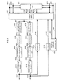
- Fig. 41 shows an example of a frame structure of a modulated signal transmitted by the transmission device in Fig. 40 .
- the transmission device is assumed to support settings for both a mode to transmit two modulated signals, z I (t) and z2(t), and for a mode to transmit one modulated signal.
- the symbol (4100) is a symbol for transmitting the "transmission information" shown in Table 1.
- the symbols (4101_1) and (4101_2) are reference (pilot) symbols for channel estimation.
- the symbols (4102_1, 4103_1) are data transmission symbols for transmitting the modulated signal z1(t).
- the symbols (4102_2, 4103_2) are data transmission symbols for transmitting the modulated signal z2(t).
- the symbol (4102_1) and the symbol (4102_2) are transmitted at the same time along the same (shared/common) frequency, and the symbol (4103_1) and the symbol (4103_2) are transmitted at the same time along the same (shared/common) frequency.
- the symbols (4102_1, 4103_1) and the symbols (4102_2, 4103_2) are the symbols after preceding matrix calculation using the method of regularly hopping between precoding matrices described in Embodiments 1-4 and Embodiment 6 (therefore, as described in Embodiment 1, the structure of the streams s1(t) and s2(t) is as in Fig. 6 ). Furthermore, in Fig. 41 , the symbol (4104) is a symbol for transmitting the "transmission information" shown in Table 1. The symbol (4105) is a reference (pilot) symbol for channel estimation. The symbols (4106, 4107) are data transmission symbols for transmitting the modulated signal z1(t). The data transmission symbols for transmitting the modulated signal z1(t) are not precoded, since the number of transmission signals is one.
- the transmission device in Fig. 40 generates and transmits modulated signals in accordance with Table 1 and the frame structure in Fig. 41 .
- the frame structure signal 313 includes information regarding the "number of transmission signals”, “modulation method”, “number of encoders”, and “error correction coding method” set based on Table 1.
- the encoder (4002), the mappers 306A, B, and the weighting units 308A, B receive the frame structure signal as an input and operate based on the "number of transmission signals”, “modulation method”, “number of encoders”, and “error correction coding method” that are set based on Table 1.
- "Transmission information” corresponding to the set “number of transmission signals”, “modulation method”, “number of encoders”, and “error correction coding method” is also transmitted to the reception device.
- the structure of the reception device may be represented similarly to Fig. 7 of Embodiment 1.
- the difference with Embodiment 1 is as follows: since the transmission device and the reception device store the information in Table 1 in advance, the transmission device does not need to transmit information for regularly hopping between precoding matrices, but rather transmits "transmission information" corresponding to the "number of transmission signals", “modulation method”, “number of encoders”, and “error correction coding method", and the reception device obtains information for regularly hopping between precoding matrices from Table I by receiving the "transmission information". Accordingly, by the control information decoding unit 709 obtaining the "transmission information" transmitted by the transmission device in Fig. 40 , the reception device in Fig.
- the signal processing unit 711 can perform detection based on a precoding matrix hopping pattern to obtain received log-likelihood ratios.
- transmission information is set with respect to the "number of transmission signals”, “modulation method”, “number of encoders”, and “error correction coding method” as in Table 1, and the precoding matrix hopping method is set with respect to the "transmission information”.
- the precoding matrix hopping method may be set with respect to the "transmission information”.
- the "transmission information" and the method of setting the precoding matrix hopping method is not limited to Tables 1 and 2.
- a rule is determined in advance for switching the precoding matrix hopping method based on transmission parameters, such as the "number of transmission signals”, “modulation method”, “number of encoders”, “error correction coding method”, or the like (as long as the transmission device and the reception device share a predetermined rule, or in other words, if the precoding matrix hopping method is switched based on any of the transmission parameters (or on any plurality of transmission parameters)), the transmission device does not need to transmit information regarding the precoding matrix hopping method.
- the reception device can identify the precoding matrix hopping method used by the transmission device by identifying the information on the transmission parameters and can therefore accurately perform decoding and detection. Note that in Tables 1 and 2, a transmission method that regularly hops between precoding matrices is used when the number of modulated transmission signals is two, but a transmission method that regularly hops between precoding matrices may be used when the number of modulated transmission signals is two or greater.
- the transmission device and reception device share a table regarding transmission patterns that includes information on precoding hopping methods, the transmission device need not transmit information regarding the precoding hopping method, transmitting instead control information that does not include information regarding the precoding hopping method, and the reception device can infer the precoding hopping method by acquiring this control information.
- the transmission device does not transmit information directly related to the method of regularly hopping between precoding matrices. Rather, a method has been described wherein the reception device infers information regarding precoding for the "method of regularly hopping between precoding matrices" used by the transmission device. This method yields the advantageous effect of improved transmission efficiency of data as a result of the transmission device not transmitting information directly related to the method of regularly hopping between precoding matrices.
- the reception device can learn the precoding hopping method by acquiring information, transmitted by the transmission device, on the number of transmission signals.
- symbols other than data symbols such as pilot symbols (preamble, unique word, postamble, reference symbol, and the like), symbols for control information, and the like may be arranged in the frame in any way. While the terms “pilot symbol” and “symbols for control information” have been used here, any term may be used, since the function itself is what is important.
- pilot symbol for example, to be a known symbol modulated with PSK modulation in the transmission and reception devices (or for the reception device to be able to synchronize in order to know the symbol transmitted by the transmission device).
- the reception device uses this symbol for frequency synchronization, time synchronization, channel estimation (estimation of Channel State Information (CSI) for each modulated signal), detection of signals, and the like.
- CSI Channel State Information
- the present invention is not limited to the above Embodiments 1-5 and may be embodied with a variety of modifications.
- the above embodiments describe communications devices, but the present invention is not limited to these devices and may be implemented as software for the corresponding communications method.
- a precoding hopping method used in a method of transmitting two modulated signals from two antennas has been described, but the present invention is not limited in this way.
- the present invention may be also embodied as a precoding hopping method for similarly changing precoding weights (matrices) in the context of a method whereby four mapped signals are precoded to generate four modulated signals that are transmitted from four antennas, or more generally, whereby N mapped signals are precoded to generate N modulated signals that are transmitted from N antennas.
- precoding and “precoding weight” are used, but any other terms may be used. What matters in the present invention is the actual signal processing.
- Each of the transmit antennas of the transmission device and the receive antennas of the reception device shown in the figures may be formed by a plurality of antennas.
- the programs for executing the above transmission method may be stored in a computer-readable recording medium, the programs stored in the recording medium may be loaded in the Random Access Memory (RAM) of the computer, and the computer may be caused to operate in accordance with the programs.
- RAM Random Access Memory
- Fig. 6 relates to the weighting method (precoding method) in the present embodiment.
- the weighting unit 600 integrates the weighting units 308A and 308B in Fig. 3 .
- the stream s1(t) and the stream s2(t) correspond to the baseband signals 307A and 307B in Fig. 3 .
- the streams s1(t) and s2(t) are the baseband signal in-phase components I and quadrature components Q when mapped according to a modulation scheme such as QPSK, 16QAM, 64QAM, or the like.
- a modulation scheme such as QPSK, 16QAM, 64QAM, or the like.
- the stream s1(t) is represented as s1(u) at symbol number u, as s1(u + 1) at symbol number u + 1, and so forth.
- the stream s2(t) is represented as s2(u) at symbol number u, as s2(u + 1) at symbol number u + 1, and so forth.
- the weighting unit 600 receives the baseband signals 307A (s1(t)) and 307B (s2(t)) and the information 315 regarding weighting information in Fig. 3 as inputs, performs weighting in accordance with the information 315 regarding weighting, and outputs the signals 309A (z1(t)) and 309B (z2(t)) after weighting in Fig. 3 .
- Equation 225 for example, z1(8i + 7) and z2(8i + 7) at time 8i + 7 are signals at the same time, and the transmission device transmits z1(8i + 7) and z2(8i + 7) over the same (shared/common) frequency.
- Equation 198 the appropriate value of ⁇ is given by Equation 198 or Equation 200.
- the present embodiment describes a precoding hopping method that increases period (cycle) size, based on the above-described precoding matrices of Equation 190.
- the poor reception points are as in Fig. 42A , and by using, as the precoding matrices, the matrices yielded by multiplying each term in the second line on the right-hand side of Equation 190 by e jX (see Equation 226), the poor reception points are rotated with respect to Fig.
- the precoding matrices F[0]-F[15] are represented as follows.
- precoding matrices F[0]-F[15] are generated (the precoding matrices F[0]-F[15] may be in any order, and the matrices F[0]-F[15] may each be different).
- Symbol number 16i may be precoded using F[0]
- symbol number 16i + 1 may be precoded using F[1]
- precoding matrices need not be hopped between regularly.
- N- period (cycle) precoding matrices are represented by the following equation.
- N ⁇ M period (cycle) precoding matrices have been set to Equation 229, the N ⁇ M period (cycle) precoding matrices may be set to the following equation, as described above.
- i 0, 1, 2, ..., N - 2, N - 1
- k 0, 1, ..., M - 2, M - 1.
- the present embodiment describes a method for regularly hopping between precoding matrices using a unitary matrix.
- the precoding matrices prepared for the N slots with reference to Equations 82-85 are represented as follows.
- Equation 231 may be represented as follows.
- Embodiment 6 describes the distance between poor reception points. In order to increase the distance between poor reception points, it is important for the number of slots N to be an odd number three or greater. The following explains this point.
- Condition #19 means that the difference in phase is 2 ⁇ /N radians.
- Condition #20 means that the difference in phase is -2 ⁇ /N radians.
- Condition #17 and Condition #18 can be replaced by the following conditions. (The number of slots in the period (cycle) is considered to be N.)
- the present embodiment describes a method for regularly hopping between precoding matrices using a unitary matrix that differs from the example in Embodiment 9.
- the precoding matrices prepared for the 2N slots are represented as follows.
- Equation 234 Let ⁇ be a fixed value (not depending on i), where ⁇ > 0. (Let the ⁇ in Equation 234 and the ⁇ in Equation 235 be the same value.) From Condition #5 (Math 106) and Condition #6 (Math 107) in Embodiment 3, the following conditions are important in Equation 234 for achieving excellent data reception quality.
- N is small, for example when N ⁇ 16, the minimum distance between poor reception points in the complex plane can be guaranteed to be a certain length, since the number of poor reception points is small. Accordingly, when N ⁇ 16, even if N is an even number, cases do exist where data reception quality can be guaranteed.
- Precoding matrices F[0]-F[2N - 1] are generated based on Equations 234 and 235 (the precoding matrices F[0]-F[2N - 1] may be arranged in any order for the 2N slots in the period (cycle)).
- Symbol number 2Ni may be precoded using F[0]
- symbol number 2Ni + 1 may be precoded using F[1], ...
- precoding matrices need not be hopped between regularly.
- the method of structuring 2N different precoding matrices for a precoding hopping method with a 2N-slot time period (cycle) has been described.
- the 2N different precoding matrices F[0], F[1], F[2], ..., F[2N - 2], F[2N - 1] are prepared.
- an example of a single carrier transmission method has been described, and therefore the case of arranging symbols in the order F[0], F[1], F[2], ..., F[2N - 2], F[2N - 1] in the time domain (or the frequency domain) has been described.
- the precoding matrix hopping method over an H-slot period (cycle) (H being a natural number larger than the number of slots 2N in the period (cycle) of the above method of regularly hopping between precoding matrices)
- H being a natural number larger than the number of slots 2N in the period (cycle) of the above method of regularly hopping between precoding matrices
- the present embodiment describes a method for regularly hopping between precoding matrices using a non-unitary matrix.
- the precoding matrices prepared for the 2N slots are represented as follows.
- Equation 236 Let ⁇ be a fixed value (not depending on i), where ⁇ > 0. (Let the ⁇ in Equation 236 and the ⁇ in Equation 237 be the same value.) From Condition #5 (Math 106) and Condition #6 (Math 107) in Embodiment 3, the following conditions are important in Equation 236 for achieving excellent data reception quality.
- Equation 237 the precoding matrices in the following Equation may be provided.
- Condition #31 means that the difference in phase is 2 ⁇ /N radians.
- Condition #32 means that the difference in phase is -2 ⁇ /N radians.
- the method of structuring 2N different precoding matrices for a precoding hopping method with a 2N-slot time period (cycle) has been described.
- the 2N different precoding matrices F[0], F[1], F[2], ..., F[2N - 2], F[2N - 1] are prepared.
- an example of a single carrier transmission method has been described, and therefore the case of arranging symbols in the order F[0], F[1], F[2]...., F[2N - 2], F[2N - 1] in the time domain (or the frequency domain) has been described.
- the present invention is not, however, limited in this way, and the 2N different precoding matrices F[0], F[1], F[2], ..., F[2N - 2], F[2N - 1] generated in the present embodiment may be adapted to a multi-carrier transmission method such as an OFDM transmission method or the like.
- precoding weights may be changed by arranging symbols in the frequency domain and in the frequency-time domain. Note that a precoding hopping method with a 2N-slot time period (cycle) has been described, but the same advantageous effects may be obtained by randomly using 2N different precoding matrices. In other words, the 2N different precoding matrices do not necessarily need to be used in a regular period (cycle).
- the precoding matrix hopping method over an H-slot period (cycle) (H being a natural number larger than the number of slots 2N in the period (cycle) of the above method of regularly hopping between precoding matrices)
- H being a natural number larger than the number of slots 2N in the period (cycle) of the above method of regularly hopping between precoding matrices
- the present embodiment describes a method for regularly hopping between precoding matrices using a non-unitary matrix.
- the precoding matrices prepared for the N slots are represented as follows.
- Condition #37 and Condition #38 are provided.
- Condition #37 means that the difference in phase is 2 ⁇ /N radians.
- Condition #38 means that the difference in phase is -2 ⁇ /N radians.
- the method of structuring N different precoding matrices for a precoding hopping method with an N-slot time period (cycle) has been described.
- the N different precoding matrices F[0], F[1], F[2], ..., F[N - 2], F[N - 1] are prepared.
- an example of a single carrier transmission method has been described, and therefore the case of arranging symbols in the order F[0], F[1], F[2], ..., F[N - 2], F[N - 1] in the time domain (or the frequency domain) has been described.
- the present invention is not, however, limited in this way, and the N different precoding matrices F[0], F[1], F[2], ..., F[N - 2], F[N - 1] generated in the present embodiment may be adapted to a multi-carrier transmission method such as an OFDM transmission method or the like.
- precoding weights may be changed by arranging symbols in the frequency domain and in the frequency-time domain. Note that a precoding hopping method with an N-slot time period (cycle) has been described, but the same advantageous effects may be obtained by randomly using N different precoding matrices. In other words, the N different precoding matrices do not necessarily need to be used in a regular period (cycle).
- Embodiment 8 The present embodiment describes a different example than Embodiment 8.
- the precoding matrices prepared for the 2N slots are represented as follows.
- Equation 240 Let ⁇ be a fixed value (not depending on i), where ⁇ > 0. (Let the ⁇ in Equation 240 and the ⁇ in Equation 241 be the same value.) Furthermore, the 2 ⁇ N ⁇ M period (cycle) precoding matrices based on Equations 240 and 241 are represented by the following equations.
- k 0, 1, ..., M - 2, M - 1.
- k 0, 1, ..., M - 2, M - 1.
- Xk Yk may be true, or Xk ⁇ Yk may be true.
- Precoding matrices F[0]-F[2 ⁇ N ⁇ M - 1] are thus generated (the precoding matrices F[0]-F[2 ⁇ N ⁇ M - 1] may be in any order for the 2 ⁇ N ⁇ M slots in the period (cycle)).
- Symbol number 2 ⁇ N ⁇ Me ⁇ i may be precoded using F[0]
- symbol number 2 ⁇ N ⁇ M ⁇ i + 1 may be precoded using F[1]
- precoding matrices need not be hopped between regularly.
- Generating the precoding matrices in this way achieves a precoding matrix hopping method with a large period (cycle), allowing for the position of poor reception points to be easily changed, which may lead to improved data reception quality.
- Equation 242 The 2 ⁇ N ⁇ M period (cycle) precoding matrices in Equation 242 may be changed to the following equation.
- k 0, 1, ..., M - 2, M - 1.
- Equation 243 The 2 ⁇ N ⁇ M period (cycle) precoding matrices in Equation 243 may also be changed to any of Equations 245-247.
- k 0, 1, ...,M-2,M- 1.
- k 0, 1, ..., M - 2, M - 1.
- k 0, 1 , ..., M - 2, M - 1.
- Equations 242 through 247 satisfy the following conditions
- ⁇ ⁇ radians is one characteristic structure, and excellent data reception quality is obtained.
- Use of a unitary matrix is another structure, and as described in detail in Embodiment 10 and Embodiment 16, if N is an odd number in Equations 242 through 247, the probability of obtaining excellent data reception quality increases.
- the present embodiment describes an example of differentiating between usage of a unitary matrix and a non-unitary matrix as the precoding matrix in the method for regularly hopping between precoding matrices.
- the advantage of the method of regularly hopping between precoding matrices is that, as described in Embodiment 6, excellent data reception quality is achieved in an LOS environment.
- the reception device performs ML calculation or applies APP (or Max-log APP) based on ML calculation, the advantageous effect is considerable.
- ML calculation greatly impacts circuit scale (calculation scale) in accordance with the modulation level of the modulation method. For example, when two precoded signals are transmitted from two antennas, and the same modulation method is used for two modulated signals (signals based on the modulation method before precoding), the number of candidate signal points in the IQ plane (received signal points 1101 in Fig.
- the modulation method is QPSK, 16QAM, or 64QAM
- ML calculation ((Max-log) APP based on ML calculation)
- linear operation such as MMSE or ZF is used in the reception device.
- ML calculation may be used for 256QAM.
- SNR Signal-to-Noise power Ratio
- the same modulation method is used for two modulated signals (signals based on the modulation method before precoding)
- a non-unitary matrix is used as the precoding matrix in the method for regularly hopping between precoding matrices
- the modulation level of the modulation method is equal to or less than 64 (or equal to or less than 256)
- a unitary matrix is used when the modulation level is greater than 64 (or greater than 256)
- the modulation level of the modulation method is equal to or less than 64 (or equal to or less than 256) as well, in some cases use of a unitary matrix may be preferable. Based on this consideration, when a plurality of modulation methods are supported in which the modulation level is equal to or less than 64 (or equal to or less than 256), it is important that in some cases, in some of the plurality of supported modulation methods where the modulation level is equal to or less than 64, a non-unitary matrix is used as the precoding matrix in the method for regularly hopping between precoding matrices.
- a non-unitary matrix is used as the precoding matrices in the method for regularly hopping between precoding matrices, whereas for modulation methods for which the modulation level is greater than ⁇ N , a unitary matrix is used. In this way, for all of the modulation methods supported by the transmission system, there is an increased probability of achieving the advantageous effect whereby excellent data reception quality is achieved for any of the modulation methods while reducing the circuit scale of the reception device.
- a non-unitary matrix may always be used as the precoding matrix in the method for regularly hopping between precoding matrices.
- a threshold 2 ⁇ may be provided for 2 a1 + a2 , and when 2 a1 + a2 ⁇ 2 ⁇ , a non-unitary matrix may be used as the precoding matrix in the method for regularly hopping between precoding matrices, whereas a unitary matrix may be used when 2 a1 + a2 > 2 ⁇ .
- a unitary matrix when 2 a1 + a2 ⁇ 2 ⁇ , in some cases use of a unitary matrix may be preferable. Based on this consideration, when a plurality of combinations of modulation methods are supported for which 2 a1 + a2 ⁇ 2 ⁇ , it is important that in some of the supported combinations of modulation methods for which 2 a1 + a2 ⁇ 2 ⁇ , a non-unitary matrix is used as the precoding matrix in the method for regularly hopping between precoding matrices.
- the reception device uses ML calculation ((Max-log) APP based on ML calculation)
- a threshold 2 ⁇ may be provided for 2 a1 + a2 + ... ai + ... + aN .
- a non-unitary matrix are used as the precoding matrix in the method for regularly hopping between precoding matrices.
- a non-unitary matrix may be used as the precoding matrix in the method for regularly hopping between precoding matrices in all of the supported combinations of modulation methods satisfying Condition #44.
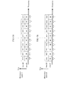
- Figs. 47A and 47B show an example according to the present embodiment of frame structure in the time and frequency domains for a signal transmitted by a broadcast station (base station) in a system that adopts a method for regularly hopping between precoding matrices using a multi-carrier transmission method such as OFDM.
- the frame structure is set to extend from time $1 to time $T.
- Fig. 47A shows the frame structure in the time and frequency domains for the stream s1 described in Embodiment 1
- Fig. 47B shows the frame structure in the time and frequency domains for the stream s2 described in Embodiment I.
- Symbols at the same time and the same (sub)carrier in stream s1 and stream s2 are transmitted by a plurality of antennas at the same time and the same frequency.
- the (sub)carriers used when using OFDM are divided as follows: a carrier group #A composed of (sub)carrier a - (sub)carrier a + Na, a carrier group #B composed of (sub)carrier b - (sub)carrier b + Nb, a carrier group #C composed of (sub)carrier c - (sub)carrier c + Nc, a carrier group #D composed of (sub)carrier d - (sub)carrier d + Nd, ....
- a carrier group #A composed of (sub)carrier a - (sub)carrier a + Na
- a carrier group #B composed of (sub)carrier b - (sub)carrier b + Nb
- a carrier group #C composed of (sub)carrier c - (sub)carrier c + Nc
- a carrier group #D composed of (sub)carrier d - (sub)carrier d + Nd
- a spatial multiplexing MIMO system or a MIMO system with a fixed precoding matrix is used for carrier group #A
- a MIMO system that regularly hops between precoding matrices is used for carrier group #B
- only stream s1 is transmitted in carrier group #C
- space-time block coding is used to transmit carrier group #D.
- Figs. 48A and 48B show an example according to the present embodiment of frame structure in the time and frequency domains for a signal transmitted by a broadcast station (base station) in a system that adopts a method for regularly hopping between precoding matrices using a multi-carrier transmission method such as OFDM.
- Figs. 48A and 48B show a frame structure at a different time than Figs. 47A and 47B , from time $X to time $X + T'.
- Figs. 48A and 48B as in Figs.
- the (sub)carriers used when using OFDM are divided as follows: a carrier group #A composed of (sub)carrier a - (sub)carrier a + Na, a carrier group #B composed of (sub)carrier b - (sub)carrier b + Nb, a carrier group #C composed of (sub)carrier c - (sub)carrier c + Nc, a carrier group #D composed of (sub)carrier d - (sub)carrier d + Nd, ....
- a carrier group #A composed of (sub)carrier a - (sub)carrier a + Na
- a carrier group #B composed of (sub)carrier b - (sub)carrier b + Nb
- a carrier group #C composed of (sub)carrier c - (sub)carrier c + Nc
- a carrier group #D composed of (sub)carrier d - (sub)carrier d + Nd
- space-time block coding is used to transmit carrier group #A
- a MIMO system that regularly hops between precoding matrices is used for carrier group #B
- a MIMO system that regularly hops between precoding matrices is used for carrier group #C
- only stream s1 is transmitted in carrier group #D.
- Fig. 49 shows a signal processing method when using a spatial multiplexing MIMO system or a MIMO system with a fixed precoding matrix.
- Fig. 49 bears the same numbers as in Fig. 6 .
- a weighting unit 600 which is a baseband signal in accordance with a certain modulation method, receives as inputs a stream s1(t) (307A), a stream s2(t) (307B), and information 315 regarding the weighting method, and outputs a modulated signal z1(t) (309A) after weighting and a modulated signal z2(t) (309B) after weighting.
- the information 315 regarding the weighting method indicates a spatial multiplexing MIMO system
- the signal processing in method #1 of Fig. 49 is performed. Specifically, the following processing is performed.
- Equation 250 When a method for transmitting one modulated signal is supported, from the standpoint of transmission power, Equation 250 may be represented as Equation 251.
- the information 315 regarding the weighting method indicates a MIMO system in which precoding matrices are regularly hopped between
- signal processing in method #2 for example, of Fig. 49 is performed. Specifically, the following processing is performed.
- ⁇ 11 , ⁇ 12 , ⁇ , and ⁇ are fixed values.
- Figs. 47A, 47B , 48A, and 48B only symbols transmitting data are shown. In practice, however, it is necessary to transmit information such as the transmission method, modulation method, error correction method, and the like. For example, as in Fig. 51 , these pieces of information can be transmitted to a communication partner by regular transmission with only one modulated signal z1. It is also necessary to transmit symbols for estimation of channel fluctuation, i.e. for the reception device to estimate channel fluctuation (for example, a pilot symbol, reference symbol, preamble, a Phase Shift Keying (PSK) symbol known at the transmission and reception sides, and the like). In Figs. 47A, 47B , 48A, and 48B , these symbols are omitted.
- PSK Phase Shift Keying
- a modulated signal generating unit #1 receives, as input, information (5200_1) and the control signal (5206) and, based on the information on the transmission method in the control signal (5206), outputs a modulated signal z1 (5202_1) and a modulated signal z2 (5203_1) in the carrier group #A of Figs. 47A, 47B , 48A, and 48B .
- a modulated signal generating unit #2 receives, as input, information (5200_ 2) and the control signal (5206) and, based on the information on the transmission method in the control signal (5206), outputs a modulated signal z1 (5202_2) and a modulated signal z2 (5203_2) in the carrier group #B of Figs. 47A, 47B , 48A, and 48B .
- a modulated signal generating unit #3 receives, as input, information (5200_3) and the control signal (5206) and, based on the information on the transmission method in the control signal (5206), outputs a modulated signal z1 (5202_3) and a modulated signal z2 (5203_3) in the carrier group #C of Figs. 47A, 47B , 48A, and 48B .
- a modulated signal generating unit #4 receives, as input, information (5200_4) and the control signal (5206) and, based on the information on the transmission method in the control signal (5206), outputs a modulated signal z1 (5202_4) and a modulated signal z2 (5203_4) in the carrier group #D of Figs. 47A, 47B , 48A, and 48B .
- modulated signal generating unit #5 While not shown in the figures, the same is true for modulated signal generating unit #M - 1.
- a modulated signal generating unit #M receives, as input, information (5200_M) and the control signal (5206) and, based on the information on the transmission method in the control signal (5206), outputs a modulated signal z1 (5202_M) and a modulated signal z2 (5203_M) in a certain carrier group.
- An OFDM related processor (5207_1) receives, as inputs, the modulated signal z1 (5202_1) in carrier group #A, the modulated signal z1 (5202_2) in carrier group #B, the modulated signal z1 (5202_3) in carrier group #C, the modulated signal z1 (5202_44) in carrier group #D, ..., the modulated signal z1 (5202_M) in a certain carrier group #M, and the control signal (5206), performs processing such as reordering, inverse Fourier transform, frequency conversion, amplification, and the like, and outputs a transmission signal (5208_1).
- the transmission signal (5208_1) is output as a radio wave from an antenna (5209_1).
- an OFDM related processor receives, as inputs, the modulated signal z1 (5203_1) in carrier group #A, the modulated signal z1 (5203_2) in carrier group #B, the modulated signal z1 (5203_3) in carrier group #C, the modulated signal z1 (5203_4) in carrier group #D, ..., the modulated signal z1 (5203_M) in a certain carrier group #M, and the control signal (5206), performs processing such as reordering, inverse Fourier transform, frequency conversion, amplification, and the like, and outputs a transmission signal (5208_2).
- the transmission signal (5208_2) is output as a radio wave from an antenna (5209_2).
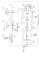
- Fig. 53 shows an example of a structure of the modulated signal generating units #1-#M in Fig. 52 .
- An error correction encoder (5302) receives, as inputs, information (5300) and a control signal (5301) and, in accordance with the control signal (5301), sets the error correction coding method and the coding ratio for error correction coding, performs error correction coding, and outputs data (5303) after error correction coding.
- An interleaver receives, as input, error correction coded data (5303) and the control signal (5301) and, in accordance with information on the interleaving method included in the control signal (5301), reorders the error correction coded data (5303) and outputs interleaved data (5305).
- a mapper (5306_1) receives, as input, the interleaved data (5305) and the control signal (5301) and, in accordance with the information on the modulation method included in the control signal (5301), performs mapping and outputs a baseband signal (5307_1).
- a mapper receives, as input, the interleaved data (5305) and the control signal (5301) and, in accordance with the information on the modulation method included in the control signal (5301), performs mapping and outputs a baseband signal (5307_2).
- a signal processing unit (5308) receives, as input, the baseband signal (5307_1), the baseband signal (5307_2), and the control signal (5301) and, based on information on the transmission method (for example, in this embodiment, a spatial multiplexing MIMO system, a MIMO method using a fixed precoding matrix, a MIMO method for regularly hopping between precoding matrices, space-time block coding, or a transmission method for transmitting only stream s1) included in the control signal (5301), performs signal processing.
- the signal processing unit (5308) outputs a processed signal z1 (5309_1) and a processed signal z2 (5309_2).
- the signal processing unit (5308) does not output the processed signal z2 (5309_2).
- the signal processing unit (5308) does not output the processed signal z2 (5309_2).
- one error correction encoder is shown, but the present invention is not limited in this way.
- a plurality of encoders may be provided.
- Fig. 54 shows an example of the structure of the OFDM related processors (5207_1 and 5207_2) in Fig. 52 . Elements that operate in a similar way to Fig. 14 bear the same reference signs.
- a reordering unit (5402A) receives, as input, the modulated signal z1 (5400_1) in carrier group #A, the modulated signal z1 (5400_2) in carrier group #B, the modulated signal z1 (5400_3) in carrier group #C, the modulated signal z1 (5400_4) in carrier group #D, ..., the modulated signal z1 (5400_M) in a certain carrier group, and a control signal (5403), performs reordering, and output reordered signals 1405A and 1405B.
- the control information symbols are for transmitting control information shared by the carrier group and are composed of symbols for the transmission and reception devices to perform frequency and time synchronization, information regarding the allocation of (sub)carriers, and the like.
- the control information symbols are set to be transmitted from only stream s1 at time $1.
- the pilot symbols are for the reception device to perform channel estimation, i.e. to estimate fluctuation corresponding to h 11 (t), h 12 (t), h 21 (t), and h 22 (t) in Equation 36.
- the pilot symbols are for estimating fluctuation corresponding to h 11 (t), h 12 (t), h 21 (t), and h 22 (t) in each subcarrier.
- the PSK transmission method for example, is used for the pilot symbols, which are structured to form a pattern known by the transmission and reception devices.
- the reception device may use the pilot symbols for estimation of frequency offset, estimation of phase distortion, and time synchronization.
- Fig. 56 shows an example of the structure of a reception device for receiving modulated signals transmitted by the transmission device in Fig. 52 .
- Elements that operate in a similar way to Fig. 7 bear the same reference signs.
- an OFDM related processor receives, as input, a received signal 702_X, performs predetermined processing, and outputs a processed signal 704_X.
- an OFDM related processor receives, as input, a received signal 702_Y, performs predetermined processing, and outputs a processed signal 704_Y.
- the channel fluctuation estimating unit 705_1 for the modulated signal z1 receives, as inputs, the processed signal 704_X and the control signal 710, performs channel estimation in the carrier group required by the reception device (the desired carrier group), and outputs a channel estimation signal 706_1.
- the channel fluctuation estimating unit 705_2 for the modulated signal z2 receives, as inputs, the processed signal 704_X and the control signal 710, performs channel estimation in the carrier group required by the reception device (the desired carrier group), and outputs a channel estimation signal 706_2.
- the channel fluctuation estimating unit 705_1 for the modulated signal z1 receives, as inputs, the processed signal 704_Y and the control signal 710, performs channel estimation in the carrier group required by the reception device (the desired carrier group), and outputs a channel estimation signal 708_1.
- the channel fluctuation estimating unit 705_2 for the modulated signal z2 receives, as inputs, the processed signal 704_Y and the control signal 710, performs channel estimation in the carrier group required by the reception device (the desired carrier group), and outputs a channel estimation signal 708_2.
- Fig. 57 shows the structure of the OFDM related processors (5600_X, 5600_Y) in Fig. 56 .
- a frequency converter (5701) receives, as input, a received signal (5700), performs frequency conversion, and outputs a frequency converted signal (5702).
- a Fourier transformer (5703) receives, as input, the frequency converted signal (5702), performs a Fourier transform, and outputs a Fourier transformed signal (5704).
- carriers are divided into a plurality of carrier groups, and the transmission method is set for each carrier group, thereby allowing for the reception quality and transmission speed to be set for each carrier group, which yields the advantageous effect of construction of a flexible system.
- allowing for choice of a method of regularly hopping between precoding matrices offers the advantages of obtaining high reception quality, as well as high transmission speed, in an LOS environment.
- the transmission methods to which a carrier group can be set are "a spatial multiplexing MIMO system, a MIMO method using a fixed precoding matrix, a MIMO method for regularly hopping between precoding matrices, space-time block coding, or a transmission method for transmitting only stream s1", but the transmission methods are not limited in this way.
- the space-time coding is not limited to the method described with reference to Fig. 50 , nor is the MIMO method using a fixed precoding matrix limited to method #2 in Fig. 49 , as any structure with a fixed precoding matrix is acceptable.
- the case of two antennas in the transmission device has been described, but when the number of antennas is larger than two as well, the same advantageous effects may be achieved by allowing for selection of a transmission method for each carrier group from among "a spatial multiplexing MIMO system, a MIMO method using a fixed precoding matrix, a MIMO method for regularly hopping between precoding matrices, space-time block coding, or a transmission method for transmitting only stream s1".
- Figs. 58A and 58B show a method of allocation into carrier groups that differs from Figs. 47A, 47B , 48A, 48B , and 51 .
- carrier groups have described as being formed by groups of subcarriers.
- the carriers in a carrier group are arranged discretely.
- Figs. 58A and 58B show an example of frame structure in the time and frequency domains that differs from Figs. 47A, 47B , 48A, 48B , 51 , 55A , and 55B .
- 58A and 58B show the frame structure for carriers I through H, times $1 through $K. Elements that are similar to Figs. 55A and 55B bear the same reference signs.
- the "A" symbols are symbols in carrier group A
- the "B” symbols are symbols in carrier group B
- the "C” symbols are symbols in carrier group C
- the "D” symbols are symbols in carrier group D.
- the carrier groups can thus be similarly implemented by discrete arrangement along (sub)carriers, and the same carrier need not always be used in the time domain. This type of arrangement yields the advantageous effect of obtaining time and frequency diversity gain.
- the present embodiment describes a method for regularly hopping between precoding matrices using a unitary matrix when N is an odd number.
- Equation 253 Let ⁇ be a fixed value (not depending on i), where ⁇ > 0. (Let the ⁇ in Equation 253 and the ⁇ in Equation 254 be the same value.) From Condition #5 (Math 106) and Condition #6 (Math 107) in Embodiment 3, the following conditions are important in Equation 253 for achieving excellent data reception quality.
- Condition #49 and Condition #50 are provided.
- Precoding matrices F[0]-F[2N - 1] are generated based on Equations 253 and 254 (the precoding matrices F[0]-F[2N - 1] may be in any order for the 2N slots in the period (cycle)).
- Symbol number 2Ni may be precoded using F[0]
- symbol number 2Ni + 1 may be precoded using F[1], ...
- precoding matrices need not be hopped between regularly.
- the method of structuring 2N different precoding matrices for a precoding hopping method with a 2N-slot time period (cycle) has been described.
- the 2N different precoding matrices F[0], F[1], F[2], ..., F[2N - 2], F[2N - 1] are prepared.
- an example of a single carrier transmission method has been described, and therefore the case of arranging symbols in the order F[0], F[1], F[2], ..., F[2N - 2], F[2N - 1] in the time domain (or the frequency domain) has been described.
- the precoding matrix hopping method over an H-slot period (cycle) (H being a natural number larger than the number of slots 2N in the period (cycle) of the above method of regularly hopping between precoding matrices)
- H being a natural number larger than the number of slots 2N in the period (cycle) of the above method of regularly hopping between precoding matrices
- data is transmitted hierarchically, and a transmission method adopting the method of regularly switching between precoding matrices described in Embodiments 1-16 is described in detail.
- Figs. 61 and 62 are an example, according to the present embodiment, of the structure of a transmission device in a broadcast station.
- An error correction encoder (6101_1) for a base stream (base layer) receives information (6100_1) of the base stream (base layer) as input, performs error correction coding, and outputs encoded information (6102_1) of the base stream (base layer).
- An error correction encoder (6101_2) for an enhancement stream receives information (6100_2) of the enhancement stream (enhancement layer) as input, performs error correction coding, and outputs encoded information (6102_2) of the enhancement stream (enhancement layer).
- An interleaver (6103_1) receives the encoded information (6102_1) of the base stream (base layer) as input, applies interleaving, and outputs interleaved, encoded data (6104_1).
Landscapes
- Engineering & Computer Science (AREA)
- Signal Processing (AREA)
- Computer Networks & Wireless Communication (AREA)
- Physics & Mathematics (AREA)
- Power Engineering (AREA)
- Mathematical Physics (AREA)
- Spectroscopy & Molecular Physics (AREA)
- Radio Transmission System (AREA)
- Detection And Prevention Of Errors In Transmission (AREA)
- Error Detection And Correction (AREA)
- Compression, Expansion, Code Conversion, And Decoders (AREA)
- Organic Low-Molecular-Weight Compounds And Preparation Thereof (AREA)
- Mobile Radio Communication Systems (AREA)
Priority Applications (2)
| Application Number | Priority Date | Filing Date | Title |
|---|---|---|---|
| EP19161609.3A EP3522409B1 (de) | 2010-10-18 | 2011-10-17 | Sendeverfahren, sendervorrichtung, empfangsverfahren und empfangsvorrichtung |
| EP21196769.0A EP4012937A3 (de) | 2010-10-18 | 2011-10-17 | Sendeverfahren, sendevorrichtung, empfangsverfahren und empfangsvorrichtung |
Applications Claiming Priority (3)
| Application Number | Priority Date | Filing Date | Title |
|---|---|---|---|
| JP2010234061 | 2010-10-18 | ||
| JP2010275164A JP5578617B2 (ja) | 2010-10-18 | 2010-12-09 | 送信方法、送信装置、受信方法および受信装置 |
| PCT/JP2011/005801 WO2012053185A1 (ja) | 2010-10-18 | 2011-10-17 | 送信方法、送信装置、受信方法および受信装置 |
Related Child Applications (3)
| Application Number | Title | Priority Date | Filing Date |
|---|---|---|---|
| EP19161609.3A Division-Into EP3522409B1 (de) | 2010-10-18 | 2011-10-17 | Sendeverfahren, sendervorrichtung, empfangsverfahren und empfangsvorrichtung |
| EP19161609.3A Division EP3522409B1 (de) | 2010-10-18 | 2011-10-17 | Sendeverfahren, sendervorrichtung, empfangsverfahren und empfangsvorrichtung |
| EP21196769.0A Division EP4012937A3 (de) | 2010-10-18 | 2011-10-17 | Sendeverfahren, sendevorrichtung, empfangsverfahren und empfangsvorrichtung |
Publications (3)
| Publication Number | Publication Date |
|---|---|
| EP2632067A1 true EP2632067A1 (de) | 2013-08-28 |
| EP2632067A4 EP2632067A4 (de) | 2017-06-21 |
| EP2632067B1 EP2632067B1 (de) | 2019-04-24 |
Family
ID=45974915
Family Applications (3)
| Application Number | Title | Priority Date | Filing Date |
|---|---|---|---|
| EP11834031.4A Active EP2632067B1 (de) | 2010-10-18 | 2011-10-17 | Sendeverfahren, sendervorrichtung, empfangsverfahren und empfangsvorrichtung |
| EP19161609.3A Active EP3522409B1 (de) | 2010-10-18 | 2011-10-17 | Sendeverfahren, sendervorrichtung, empfangsverfahren und empfangsvorrichtung |
| EP21196769.0A Pending EP4012937A3 (de) | 2010-10-18 | 2011-10-17 | Sendeverfahren, sendevorrichtung, empfangsverfahren und empfangsvorrichtung |
Family Applications After (2)
| Application Number | Title | Priority Date | Filing Date |
|---|---|---|---|
| EP19161609.3A Active EP3522409B1 (de) | 2010-10-18 | 2011-10-17 | Sendeverfahren, sendervorrichtung, empfangsverfahren und empfangsvorrichtung |
| EP21196769.0A Pending EP4012937A3 (de) | 2010-10-18 | 2011-10-17 | Sendeverfahren, sendevorrichtung, empfangsverfahren und empfangsvorrichtung |
Country Status (19)
| Country | Link |
|---|---|
| US (15) | US8831134B2 (de) |
| EP (3) | EP2632067B1 (de) |
| JP (1) | JP5578617B2 (de) |
| KR (2) | KR101880943B1 (de) |
| CN (3) | CN105577326B (de) |
| AR (1) | AR083419A1 (de) |
| AU (3) | AU2011319338B2 (de) |
| BR (1) | BR112013003680B1 (de) |
| CA (3) | CA2803905C (de) |
| EA (1) | EA031617B1 (de) |
| IL (3) | IL223915A (de) |
| MX (1) | MX2013000955A (de) |
| MY (1) | MY161371A (de) |
| PE (2) | PE20131091A1 (de) |
| PH (1) | PH12016501580A1 (de) |
| SG (2) | SG10201508441WA (de) |
| TW (4) | TWI618381B (de) |
| WO (1) | WO2012053185A1 (de) |
| ZA (2) | ZA201300697B (de) |
Families Citing this family (30)
| Publication number | Priority date | Publication date | Assignee | Title |
|---|---|---|---|---|
| JP5578617B2 (ja) | 2010-10-18 | 2014-08-27 | パナソニック インテレクチュアル プロパティ コーポレーション オブ アメリカ | 送信方法、送信装置、受信方法および受信装置 |
| CL2013000511A1 (es) * | 2010-10-18 | 2013-08-09 | Panasonic Corp | Metodo de de precodificacion para generar a partir de multiples señales de banda base, multiples señales precodificadas que deben transmitirse por el mismo ancho de banda de frecuencias al mismo tiempo; y aparato asociado |
| EP2701327B1 (de) | 2011-04-19 | 2024-05-29 | Sun Patent Trust | Vorkodierungsverfahren und vorkodierungsvorrichtung |
| EP3035575B1 (de) | 2011-04-19 | 2017-07-26 | Sun Patent Trust | Kommunikationsverfahren und -vorrichtung |
| US8811545B2 (en) * | 2011-11-08 | 2014-08-19 | Mitsubishi Electric Research Laboratories, Inc. | Method for reducing interference in OFDM wireless networks |
| WO2014087674A1 (ja) * | 2012-12-07 | 2014-06-12 | パナソニック株式会社 | 信号生成方法、送信装置、受信方法および受信装置 |
| EP2988510A4 (de) * | 2013-04-15 | 2016-11-16 | Lg Electronics Inc | Verfahren zum senden von rundfunksignalen, verfahren zum empfangen von rundfunksignalen sowie verfahren zum senden von rundfunksignalen und vorrichtung zum empfangen von rundfunksignalen |
| US9548836B2 (en) * | 2013-11-26 | 2017-01-17 | Broadcom Corporation | Upstream burst noise detection |
| EP3068057B1 (de) * | 2013-12-30 | 2021-07-28 | Huawei Technologies Co., Ltd. | Datenübertragungsverfahren und -vorrichtung |
| KR102191290B1 (ko) * | 2014-01-29 | 2020-12-15 | 삼성전자 주식회사 | 이동통신 시스템에서 통신 채널 추정 방법 및 장치 |
| WO2015119009A1 (ja) | 2014-02-06 | 2015-08-13 | 日本電信電話株式会社 | 基地局装置、無線通信システム、および通信方法 |
| MX361435B (es) | 2015-01-05 | 2018-12-06 | Lg Electronics Inc | Aparato de transmision de señales de difusion, aparato de recepcion de señales de difusion, metodo de transmision de señales de difusion, y metodo de recepcion de señales de difusion. |
| JP6507047B2 (ja) * | 2015-02-10 | 2019-04-24 | 日本放送協会 | 送信装置、受信装置、及び半導体チップ |
| CN108353051B (zh) * | 2015-11-05 | 2021-02-23 | 瑞典爱立信有限公司 | 无线电预编码 |
| US10411944B2 (en) | 2016-02-29 | 2019-09-10 | Panasonic Intellectual Property Corporation Of America | Transmission method, transmission device, reception method, and reception device |
| WO2017162296A1 (en) * | 2016-03-24 | 2017-09-28 | Huawei Technologies Co., Ltd. | Method and node in a wireless communication network |
| CN109417532B (zh) * | 2016-07-14 | 2021-08-24 | 苹果公司 | 发送方法、发送装置、接收方法及接收装置 |
| RU2734653C2 (ru) * | 2016-07-15 | 2020-10-21 | Панасоник Интеллекчуал Проперти Корпорэйшн оф Америка | Устройство передачи и способ передачи |
| JP6696336B2 (ja) * | 2016-07-20 | 2020-05-20 | 富士通株式会社 | 送信制御装置、無線通信システム及びキャリブレーション方法 |
| KR101825301B1 (ko) * | 2016-08-22 | 2018-02-02 | 한양대학교 산학협력단 | 신호 전송 장치 및 방법과, 신호 수신 장치 |
| EP3537623B1 (de) * | 2016-11-04 | 2021-12-22 | Panasonic Intellectual Property Corporation of America | Sendevorrichtung, sendeverfahren, empfangsvorrichtung und empfangsverfahren |
| JP6686170B2 (ja) * | 2016-11-11 | 2020-04-22 | 日本電信電話株式会社 | 無線通信システム及び無線通信方法 |
| JP7024216B2 (ja) * | 2017-06-15 | 2022-02-24 | 富士通株式会社 | 送信制御装置、無線通信システム及び無線リソース割当方法 |
| CN107911152B (zh) * | 2017-10-27 | 2020-11-24 | 西安电子科技大学 | 适用于任意发送天线数量的空间编码调制系统和方法 |
| KR101938334B1 (ko) * | 2017-10-30 | 2019-04-11 | 서울과학기술대학교 산학협력단 | 스테레오스코픽 3차원 영상 송수신 장치 및 방법 |
| US10726843B2 (en) * | 2017-12-20 | 2020-07-28 | Facebook, Inc. | Methods and systems for responding to inquiries based on social graph information |
| CN112396819B (zh) * | 2019-08-16 | 2022-06-03 | 北京小米移动软件有限公司 | 红外通信装置、系统、方法、终端设备及存储介质 |
| CN110784864B (zh) * | 2019-11-01 | 2022-03-18 | 中国电子科技集团公司第三十研究所 | 一种星地链路设备射频指纹识别及安全接入认证方法 |
| US12088398B1 (en) | 2020-02-29 | 2024-09-10 | Space Exploration Technologies Corp. | Configurable orthogonal frequency division multiplexing (OFDM) signal and transmitter and receiver for same |
| US11863359B1 (en) * | 2021-05-11 | 2024-01-02 | Amazon Technologies, Inc. | Subcarrier pre-equalization technology for frequency selective fading characteristics of wireless channels |
Family Cites Families (91)
| Publication number | Priority date | Publication date | Assignee | Title |
|---|---|---|---|---|
| KR100353338B1 (ko) * | 1999-03-17 | 2002-09-18 | 소니 가부시끼 가이샤 | 확산 스펙트럼 통신 장치 |
| US7139324B1 (en) | 2000-06-02 | 2006-11-21 | Nokia Networks Oy | Closed loop feedback system for improved down link performance |
| US6859503B2 (en) * | 2001-04-07 | 2005-02-22 | Motorola, Inc. | Method and system in a transceiver for controlling a multiple-input, multiple-output communications channel |
| US6785341B2 (en) | 2001-05-11 | 2004-08-31 | Qualcomm Incorporated | Method and apparatus for processing data in a multiple-input multiple-output (MIMO) communication system utilizing channel state information |
| US7072413B2 (en) * | 2001-05-17 | 2006-07-04 | Qualcomm, Incorporated | Method and apparatus for processing data for transmission in a multi-channel communication system using selective channel inversion |
| KR100866195B1 (ko) * | 2001-11-10 | 2008-10-30 | 삼성전자주식회사 | 직교주파수분할다중 방식의 이동통신시스템에서 시공간-주파수 부호화/복호화 장치 및 방법 |
| US6687492B1 (en) * | 2002-03-01 | 2004-02-03 | Cognio, Inc. | System and method for antenna diversity using joint maximal ratio combining |
| US7197084B2 (en) | 2002-03-27 | 2007-03-27 | Qualcomm Incorporated | Precoding for a multipath channel in a MIMO system |
| JP2003332940A (ja) * | 2002-05-09 | 2003-11-21 | Matsushita Electric Ind Co Ltd | 移動体通信装置 |
| DE10220892A1 (de) * | 2002-05-10 | 2003-12-18 | Fraunhofer Ges Forschung | Sendevorrichtung und Empfangsvorrichtung |
| US7653415B2 (en) * | 2002-08-21 | 2010-01-26 | Broadcom Corporation | Method and system for increasing data rate in a mobile terminal using spatial multiplexing for DVB-H communication |
| US7324429B2 (en) | 2002-10-25 | 2008-01-29 | Qualcomm, Incorporated | Multi-mode terminal in a wireless MIMO system |
| US8027704B2 (en) * | 2003-08-21 | 2011-09-27 | Broadcom Corporation | Method and system for increasing data rate in a mobile terminal using spatial multiplexing for DVB-H communication |
| EP2690814A1 (de) | 2003-11-21 | 2014-01-29 | Panasonic Corporation | Mehrfachantennenvorrichtung mittels verschiedener Interleaving-Muster |
| US7212821B2 (en) * | 2003-12-05 | 2007-05-01 | Qualcomm Incorporated | Methods and apparatus for performing handoffs in a multi-carrier wireless communications system |
| CN103516459B (zh) * | 2004-03-15 | 2016-09-21 | 苹果公司 | 用于具有四根发射天线的ofdm系统的导频设计 |
| US8571086B2 (en) * | 2004-04-02 | 2013-10-29 | Rearden, Llc | System and method for DIDO precoding interpolation in multicarrier systems |
| US10187133B2 (en) * | 2004-04-02 | 2019-01-22 | Rearden, Llc | System and method for power control and antenna grouping in a distributed-input-distributed-output (DIDO) network |
| US10277290B2 (en) * | 2004-04-02 | 2019-04-30 | Rearden, Llc | Systems and methods to exploit areas of coherence in wireless systems |
| KR100754795B1 (ko) | 2004-06-18 | 2007-09-03 | 삼성전자주식회사 | 직교주파수분할다중 시스템에서 주파수 공간 블록 부호의부호화/복호화 장치 및 방법 |
| US8130855B2 (en) * | 2004-11-12 | 2012-03-06 | Interdigital Technology Corporation | Method and apparatus for combining space-frequency block coding, spatial multiplexing and beamforming in a MIMO-OFDM system |
| US7525988B2 (en) * | 2005-01-17 | 2009-04-28 | Broadcom Corporation | Method and system for rate selection algorithm to maximize throughput in closed loop multiple input multiple output (MIMO) wireless local area network (WLAN) system |
| US7561632B1 (en) * | 2005-04-28 | 2009-07-14 | Qualcomm Incorporated | Beamforming techniques for MIMO communication systems |
| KR101124932B1 (ko) | 2005-05-30 | 2012-03-28 | 삼성전자주식회사 | 어레이 안테나를 이용하는 이동 통신 시스템에서의 데이터송/수신 장치 및 방법 |
| US7564917B2 (en) * | 2005-11-01 | 2009-07-21 | Intel Corporation | Multicarrier receiver and method for generating common phase error estimates for use in systems that employ two or more transmit antennas with independent local oscillators |
| US7881258B2 (en) * | 2006-03-22 | 2011-02-01 | Sibeam, Inc. | Mechanism for streaming media data over wideband wireless networks |
| US7991090B2 (en) * | 2006-05-04 | 2011-08-02 | Broadcom Corporation | Method and system for reordered QRV-LST (layered space time) detection for efficient processing for multiple input multiple output (MIMO) communication systems |
| JP4946159B2 (ja) * | 2006-05-09 | 2012-06-06 | 富士通株式会社 | 無線送信方法及び無線受信方法並びに無線送信装置及び無線受信装置 |
| US7949064B2 (en) | 2006-08-14 | 2011-05-24 | Texas Instruments Incorporated | Codebook and pre-coder selection for closed-loop mimo |
| TWI479822B (zh) * | 2006-08-17 | 2015-04-01 | Intel Corp | Mimo無線通信系統中有效率預編碼反饋提供方法及裝置 |
| KR100878768B1 (ko) * | 2006-09-15 | 2009-01-14 | 삼성전자주식회사 | Mimo ofdm 송수신 방법 및 장치 |
| KR20080026010A (ko) | 2006-09-19 | 2008-03-24 | 엘지전자 주식회사 | 위상천이 기반의 프리코딩을 이용한 데이터 전송 방법 및이를 구현하는 송수신 장치 |
| BRPI0720512A2 (pt) * | 2006-10-04 | 2014-11-18 | Qualcomm Inc | Transmissão de ack em uplink para sdma em um sistema de comunicação sem fio |
| JP5519286B2 (ja) * | 2006-10-18 | 2014-06-11 | 韓國電子通信研究院 | Ofdmセルラーシステムのためのtdmベースのセルサーチ方法 |
| CN101529777A (zh) * | 2006-10-23 | 2009-09-09 | Lg电子株式会社 | 用于使用循环延迟分集发射数据的方法 |
| JP5089339B2 (ja) * | 2006-11-02 | 2012-12-05 | パナソニック株式会社 | 送信方法、送信装置及び受信方法 |
| WO2008062587A1 (fr) * | 2006-11-22 | 2008-05-29 | Fujitsu Limited | Système et procédé de communication mimo-ofdm |
| US20080151831A1 (en) * | 2006-12-22 | 2008-06-26 | Farooq Khan | Orthogonal repetition and hybrid ARQ scheme |
| US9065714B2 (en) * | 2007-01-10 | 2015-06-23 | Qualcomm Incorporated | Transmission of information using cyclically shifted sequences |
| CN101578779A (zh) | 2007-01-19 | 2009-11-11 | 松下电器产业株式会社 | 多天线发送装置、多天线接收装置、多天线发送方法、多天线接收方法、终端装置以及基站装置 |
| US8290079B2 (en) * | 2007-04-19 | 2012-10-16 | Interdigital Technology Corporation | Method and apparatus for precoding validation in wireless communications |
| US8254492B2 (en) * | 2007-04-26 | 2012-08-28 | Samsung Electronics Co., Ltd. | Transmit diversity in a wireless communication system |
| EP2584713A3 (de) * | 2007-06-19 | 2014-01-15 | NTT DoCoMo, Inc. | Sender und Sendeverfahren |
| US8160177B2 (en) | 2007-06-25 | 2012-04-17 | Samsung Electronics Co., Ltd. | Transmit methods with delay diversity and space-frequency diversity |
| KR20080114452A (ko) * | 2007-06-26 | 2008-12-31 | 엘지전자 주식회사 | 다중 안테나 시스템에서 데이터 전송방법 및 코드북구성방법 |
| US8184726B2 (en) * | 2007-09-10 | 2012-05-22 | Industrial Technology Research Institute | Method and apparatus for multi-rate control in a multi-channel communication system |
| DK2056549T3 (da) * | 2007-10-30 | 2013-02-04 | Sony Corp | Databehandlingsanordning og -fremgangsmåde |
| US20090116589A1 (en) * | 2007-11-01 | 2009-05-07 | Renesas Technology Corporation | Performance-based link adaptation techniques |
| RU2452129C2 (ru) * | 2008-01-14 | 2012-05-27 | Телефонактиеболагет Лм Эрикссон (Пабл) | Разомкнутый прекодирующий цикл в mimo-связи |
| KR101328961B1 (ko) * | 2008-03-14 | 2013-11-13 | 엘지전자 주식회사 | 개루프 공간 다중화 모드에서 신호 송수신 방법 |
| KR20090101804A (ko) * | 2008-03-24 | 2009-09-29 | 엘지전자 주식회사 | 랭크 적응형 4Tx 시스템을 위한 개루프 방식의 공간분할 다중화 방법 |
| CA2720187A1 (en) * | 2008-03-31 | 2009-10-08 | Sirius Xm Radio Inc. | Improving slow speed mute resistance via selective cofdm bin loading |
| CN102007747B (zh) * | 2008-04-18 | 2014-12-03 | 皇家飞利浦电子股份有限公司 | 改进的双载波调制预编码 |
| WO2009153809A2 (en) | 2008-06-18 | 2009-12-23 | Centre Of Excellence In Wireless Technology | Precoding for single transmission streams in multiple antenna systems |
| KR101527009B1 (ko) * | 2008-07-11 | 2015-06-18 | 엘지전자 주식회사 | 다중 셀 기반에서 멀티-셀 mimo 적용 방법 |
| KR101027237B1 (ko) * | 2008-07-30 | 2011-04-06 | 엘지전자 주식회사 | 다중안테나 시스템에서 데이터 전송방법 |
| KR101056614B1 (ko) * | 2008-07-30 | 2011-08-11 | 엘지전자 주식회사 | 다중안테나 시스템에서 데이터 전송방법 |
| US8654752B2 (en) * | 2008-08-05 | 2014-02-18 | Panasonic Corporation | Radio communication device and radio communication method |
| KR101440628B1 (ko) * | 2008-08-11 | 2014-09-17 | 엘지전자 주식회사 | Sc-fdma 시스템에서 전송 다이버시티를 이용한 데이터 전송장치 및 방법 |
| WO2010038474A1 (ja) * | 2008-10-03 | 2010-04-08 | パナソニック株式会社 | 無線送信装置、移動局装置及びプリコーディング方法 |
| KR101435846B1 (ko) * | 2008-10-30 | 2014-08-29 | 엘지전자 주식회사 | 다중안테나를 갖는 무선 통신 시스템에서 간섭 제어 방법 |
| AU2008363680B2 (en) * | 2008-10-31 | 2014-11-27 | Telefonaktiebolaget Lm Ericsson (Publ) | Channel-assisted iterative precoder selection |
| KR101619964B1 (ko) | 2008-11-02 | 2016-05-23 | 엘지전자 주식회사 | 다중 입출력 시스템에서 공간 다중화 프리코딩 방법 |
| KR101582685B1 (ko) * | 2008-12-03 | 2016-01-06 | 엘지전자 주식회사 | 다중안테나를 이용한 데이터 전송장치 및 방법 |
| US8693560B2 (en) * | 2009-01-08 | 2014-04-08 | Sharp Kabushiki Kaisha | Transmission apparatus, transmission method, communication system, and communication method |
| WO2010096329A2 (en) | 2009-02-18 | 2010-08-26 | Massachusetts Institute Of Technology | Method and apparatus for synchronizing a wireless communication system |
| KR101753391B1 (ko) * | 2009-03-30 | 2017-07-04 | 엘지전자 주식회사 | 무선 통신 시스템에서 신호 전송 방법 및 장치 |
| CN101867426A (zh) * | 2009-04-15 | 2010-10-20 | Lg电子株式会社 | 广播接收系统及广播信号处理方法 |
| JP2011004161A (ja) | 2009-06-18 | 2011-01-06 | Sharp Corp | 通信システム、通信装置および通信方法 |
| KR20120089635A (ko) * | 2009-08-18 | 2012-08-13 | 주식회사 팬택 | 무선 통신 시스템에서의 피드백 채널 정보 |
| EP2293483B1 (de) * | 2009-09-04 | 2016-07-27 | STMicroelectronics Srl | Verfahren und Vorrichtung zur Soft-Ausgabe-Detektion in einem Kommunikationssystemen mit mehreren Antennen. |
| WO2011028079A2 (ko) * | 2009-09-07 | 2011-03-10 | 엘지전자 주식회사 | 무선 통신 시스템에서 참조신호를 송수신하기 위한 방법 및 장치 |
| JP5149257B2 (ja) * | 2009-10-02 | 2013-02-20 | シャープ株式会社 | 無線通信システム、通信装置および無線通信方法 |
| EP2346224A1 (de) * | 2010-01-13 | 2011-07-20 | Panasonic Corporation | Pilotmuster für OFDM-Systeme mit vier Übertragungsantennen |
| US9197284B2 (en) * | 2010-01-15 | 2015-11-24 | Google Technology Holdings LLC | Method and apparatus for pilot signal processing in a wireless communication system |
| KR101814394B1 (ko) * | 2010-01-17 | 2018-01-03 | 엘지전자 주식회사 | 무선 통신 시스템에서 제어 정보의 전송 방법 및 장치 |
| KR101733489B1 (ko) * | 2010-01-17 | 2017-05-24 | 엘지전자 주식회사 | 무선 통신 시스템에서 제어 정보의 전송 방법 및 장치 |
| TWI581578B (zh) * | 2010-02-26 | 2017-05-01 | 新力股份有限公司 | 編碼器及提供遞增冗餘之編碼方法 |
| US8520572B2 (en) * | 2010-05-05 | 2013-08-27 | Motorola Mobility Llc | Multiplexing control and data on multilayer uplink transmissions |
| WO2011142626A2 (ko) * | 2010-05-13 | 2011-11-17 | 엘지전자 주식회사 | Mimo 무선 통신 시스템에서 제어 정보 및 데이터의 다중화 전송 방법 및 장치 |
| US8494033B2 (en) * | 2010-06-15 | 2013-07-23 | Telefonaktiebolaget L M Ericsson (Publ) | Methods providing precoder feedback using multiple precoder indices and related communications devices and systems |
| EP2445131B1 (de) * | 2010-06-17 | 2016-02-10 | Panasonic Intellectual Property Corporation of America | Vor-kodierungsverfahren und sender-empfänger |
| JP5578617B2 (ja) | 2010-10-18 | 2014-08-27 | パナソニック インテレクチュアル プロパティ コーポレーション オブ アメリカ | 送信方法、送信装置、受信方法および受信装置 |
| US8687727B2 (en) * | 2010-11-05 | 2014-04-01 | Intel Corporation | Coordinated multi-point transmission using interference feedback |
| JP5991572B2 (ja) * | 2011-02-28 | 2016-09-14 | サン パテント トラスト | 送信方法および送信装置 |
| CN102684819B (zh) * | 2011-03-15 | 2015-06-03 | 华为技术有限公司 | 一种数据传输方法及相关设备、系统 |
| EP3035575B1 (de) * | 2011-04-19 | 2017-07-26 | Sun Patent Trust | Kommunikationsverfahren und -vorrichtung |
| EP2701327B1 (de) * | 2011-04-19 | 2024-05-29 | Sun Patent Trust | Vorkodierungsverfahren und vorkodierungsvorrichtung |
| US9167451B2 (en) * | 2013-01-02 | 2015-10-20 | Lg Electronics Inc. | Method and apparatus for measuring interference in wireless communication system |
| JP2017011689A (ja) * | 2015-06-19 | 2017-01-12 | パナソニック インテレクチュアル プロパティ コーポレーション オブ アメリカPanasonic Intellectual Property Corporation of America | 送信方法、受信方法、送信装置、及び受信装置 |
| US10736081B2 (en) * | 2016-09-14 | 2020-08-04 | Huawei Technologies Co., Ltd. | Non-orthogonal multiple access transmission |
-
2010
- 2010-12-09 JP JP2010275164A patent/JP5578617B2/ja active Active
-
2011
- 2011-10-17 EP EP11834031.4A patent/EP2632067B1/de active Active
- 2011-10-17 EP EP19161609.3A patent/EP3522409B1/de active Active
- 2011-10-17 MY MYPI2013000191A patent/MY161371A/en unknown
- 2011-10-17 CN CN201610111937.5A patent/CN105577326B/zh active Active
- 2011-10-17 EP EP21196769.0A patent/EP4012937A3/de active Pending
- 2011-10-17 AU AU2011319338A patent/AU2011319338B2/en active Active
- 2011-10-17 WO PCT/JP2011/005801 patent/WO2012053185A1/ja active Application Filing
- 2011-10-17 MX MX2013000955A patent/MX2013000955A/es active IP Right Grant
- 2011-10-17 CN CN201610112189.2A patent/CN105721111B/zh active Active
- 2011-10-17 PE PE2013000176A patent/PE20131091A1/es active IP Right Grant
- 2011-10-17 PE PE2017002823A patent/PE20180583A1/es unknown
- 2011-10-17 KR KR1020137000344A patent/KR101880943B1/ko active IP Right Grant
- 2011-10-17 CA CA2803905A patent/CA2803905C/en active Active
- 2011-10-17 CN CN201180035360.XA patent/CN103004120B/zh active Active
- 2011-10-17 US US13/811,021 patent/US8831134B2/en active Active
- 2011-10-17 SG SG10201508441WA patent/SG10201508441WA/en unknown
- 2011-10-17 BR BR112013003680-0A patent/BR112013003680B1/pt active IP Right Grant
- 2011-10-17 SG SG2013002209A patent/SG187029A1/en unknown
- 2011-10-17 CA CA3017162A patent/CA3017162C/en active Active
- 2011-10-17 CA CA3066278A patent/CA3066278C/en active Active
- 2011-10-17 EA EA201390045A patent/EA031617B1/ru not_active IP Right Cessation
- 2011-10-17 KR KR1020187020333A patent/KR101995761B1/ko active IP Right Grant
- 2011-10-17 AR ARP110103828A patent/AR083419A1/es active IP Right Grant
- 2011-10-18 TW TW105113859A patent/TWI618381B/zh active
- 2011-10-18 TW TW106146038A patent/TWI643481B/zh active
- 2011-10-18 TW TW107135606A patent/TWI687066B/zh active
- 2011-10-18 TW TW100137708A patent/TWI540854B/zh active
-
2012
- 2012-12-27 IL IL223915A patent/IL223915A/en active IP Right Grant
-
2013
- 2013-01-25 ZA ZA2013/00697A patent/ZA201300697B/en unknown
-
2014
- 2014-07-30 US US14/447,027 patent/US9048985B2/en active Active
-
2015
- 2015-03-11 US US14/644,834 patent/US9136929B2/en active Active
- 2015-07-21 US US14/804,733 patent/US9344171B2/en active Active
-
2016
- 2016-04-15 US US15/130,007 patent/US9467215B2/en active Active
- 2016-08-10 PH PH12016501580A patent/PH12016501580A1/en unknown
- 2016-09-01 US US15/254,473 patent/US9800306B2/en active Active
- 2016-11-04 AU AU2016253675A patent/AU2016253675B2/en active Active
- 2016-12-14 IL IL249556A patent/IL249556B/en active IP Right Grant
-
2017
- 2017-09-13 US US15/703,360 patent/US9935697B2/en active Active
-
2018
- 2018-02-07 US US15/890,935 patent/US10050685B2/en active Active
- 2018-07-10 US US16/031,301 patent/US10270503B2/en active Active
- 2018-10-25 AU AU2018253552A patent/AU2018253552B2/en active Active
-
2019
- 2019-01-13 IL IL26421319A patent/IL264213B/en active IP Right Grant
- 2019-03-18 US US16/356,598 patent/US10560160B2/en active Active
- 2019-04-17 ZA ZA2019/02449A patent/ZA201902449B/en unknown
- 2019-12-24 US US16/726,531 patent/US10700746B2/en active Active
-
2020
- 2020-05-18 US US16/876,807 patent/US10965354B2/en active Active
-
2021
- 2021-02-05 US US17/168,955 patent/US11456785B2/en active Active
-
2022
- 2022-08-29 US US17/897,794 patent/US11729033B2/en active Active
-
2023
- 2023-06-15 US US18/210,380 patent/US12081379B2/en active Active
Also Published As
Similar Documents
| Publication | Publication Date | Title |
|---|---|---|
| US10965354B2 (en) | Transmission method, transmission device, reception method, and reception device | |
| US11296756B2 (en) | Receiving method and receiving apparatus | |
| EP3032769B1 (de) | Vorcodierungsverfahren und sender | |
| EP2615757B1 (de) | Sendeverfahren, sendevorrichtung, empfangsverfahren und empfängervorrichtung | |
| KR102291389B1 (ko) | 송신방법, 송신장치, 수신방법 및 수신장치 | |
| EP2701327B1 (de) | Vorkodierungsverfahren und vorkodierungsvorrichtung | |
| EP2651064B1 (de) | Vorcodierungsverfahren und sendevorrichtung | |
| EP2680473B1 (de) | Präkodierungsverfahren und präkodierungsvorrichtung | |
| EP2445131B1 (de) | Vor-kodierungsverfahren und sender-empfänger |
Legal Events
| Date | Code | Title | Description |
|---|---|---|---|
| PUAI | Public reference made under article 153(3) epc to a published international application that has entered the european phase |
Free format text: ORIGINAL CODE: 0009012 |
|
| 17P | Request for examination filed |
Effective date: 20130118 |
|
| AK | Designated contracting states |
Kind code of ref document: A1 Designated state(s): AL AT BE BG CH CY CZ DE DK EE ES FI FR GB GR HR HU IE IS IT LI LT LU LV MC MK MT NL NO PL PT RO RS SE SI SK SM TR |
|
| REG | Reference to a national code |
Ref country code: HK Ref legal event code: DE Ref document number: 1183568 Country of ref document: HK |
|
| DAX | Request for extension of the european patent (deleted) | ||
| RAP1 | Party data changed (applicant data changed or rights of an application transferred) |
Owner name: PANASONIC INTELLECTUAL PROPERTY CORPORATION OF AME |
|
| RAP1 | Party data changed (applicant data changed or rights of an application transferred) |
Owner name: SUN PATENT TRUST |
|
| RA4 | Supplementary search report drawn up and despatched (corrected) |
Effective date: 20170523 |
|
| RIC1 | Information provided on ipc code assigned before grant |
Ipc: H04L 25/00 20060101ALI20170517BHEP Ipc: H04J 99/00 20090101AFI20170517BHEP Ipc: H04B 7/04 20170101ALI20170517BHEP Ipc: H04L 25/03 20060101ALI20170517BHEP Ipc: H04B 7/0417 20170101ALI20170517BHEP |
|
| GRAP | Despatch of communication of intention to grant a patent |
Free format text: ORIGINAL CODE: EPIDOSNIGR1 |
|
| STAA | Information on the status of an ep patent application or granted ep patent |
Free format text: STATUS: GRANT OF PATENT IS INTENDED |
|
| RIC1 | Information provided on ipc code assigned before grant |
Ipc: H04B 7/04 20060101ALI20181008BHEP Ipc: H04L 25/00 20060101ALI20181008BHEP Ipc: H04L 25/03 20060101ALI20181008BHEP Ipc: H04J 99/00 20090101AFI20181008BHEP Ipc: H04B 7/0417 20130828ALI20181008BHEP |
|
| INTG | Intention to grant announced |
Effective date: 20181113 |
|
| RIC1 | Information provided on ipc code assigned before grant |
Ipc: H04B 7/04 20170101ALI20181008BHEP Ipc: H04L 25/00 20060101ALI20181008BHEP Ipc: H04B 7/0417 20170101ALI20181008BHEP Ipc: H04J 99/00 20090101AFI20181008BHEP Ipc: H04L 25/03 20060101ALI20181008BHEP |
|
| RIC1 | Information provided on ipc code assigned before grant |
Ipc: H04B 7/0417 20170101ALI20181008BHEP Ipc: H04L 25/03 20060101ALI20181008BHEP Ipc: H04J 99/00 20090101AFI20181008BHEP Ipc: H04B 7/04 20170101ALI20181008BHEP Ipc: H04L 25/00 20060101ALI20181008BHEP |
|
| GRAS | Grant fee paid |
Free format text: ORIGINAL CODE: EPIDOSNIGR3 |
|
| GRAA | (expected) grant |
Free format text: ORIGINAL CODE: 0009210 |
|
| STAA | Information on the status of an ep patent application or granted ep patent |
Free format text: STATUS: THE PATENT HAS BEEN GRANTED |
|
| AK | Designated contracting states |
Kind code of ref document: B1 Designated state(s): AL AT BE BG CH CY CZ DE DK EE ES FI FR GB GR HR HU IE IS IT LI LT LU LV MC MK MT NL NO PL PT RO RS SE SI SK SM TR |
|
| REG | Reference to a national code |
Ref country code: GB Ref legal event code: FG4D |
|
| REG | Reference to a national code |
Ref country code: CH Ref legal event code: EP |
|
| REG | Reference to a national code |
Ref country code: AT Ref legal event code: REF Ref document number: 1125390 Country of ref document: AT Kind code of ref document: T Effective date: 20190515 Ref country code: IE Ref legal event code: FG4D |
|
| REG | Reference to a national code |
Ref country code: DE Ref legal event code: R096 Ref document number: 602011058388 Country of ref document: DE |
|
| REG | Reference to a national code |
Ref country code: NL Ref legal event code: MP Effective date: 20190424 |
|
| REG | Reference to a national code |
Ref country code: LT Ref legal event code: MG4D |
|
| PG25 | Lapsed in a contracting state [announced via postgrant information from national office to epo] |
Ref country code: NL Free format text: LAPSE BECAUSE OF FAILURE TO SUBMIT A TRANSLATION OF THE DESCRIPTION OR TO PAY THE FEE WITHIN THE PRESCRIBED TIME-LIMIT Effective date: 20190424 |
|
| PG25 | Lapsed in a contracting state [announced via postgrant information from national office to epo] |
Ref country code: AL Free format text: LAPSE BECAUSE OF FAILURE TO SUBMIT A TRANSLATION OF THE DESCRIPTION OR TO PAY THE FEE WITHIN THE PRESCRIBED TIME-LIMIT Effective date: 20190424 Ref country code: PT Free format text: LAPSE BECAUSE OF FAILURE TO SUBMIT A TRANSLATION OF THE DESCRIPTION OR TO PAY THE FEE WITHIN THE PRESCRIBED TIME-LIMIT Effective date: 20190824 Ref country code: ES Free format text: LAPSE BECAUSE OF FAILURE TO SUBMIT A TRANSLATION OF THE DESCRIPTION OR TO PAY THE FEE WITHIN THE PRESCRIBED TIME-LIMIT Effective date: 20190424 Ref country code: LT Free format text: LAPSE BECAUSE OF FAILURE TO SUBMIT A TRANSLATION OF THE DESCRIPTION OR TO PAY THE FEE WITHIN THE PRESCRIBED TIME-LIMIT Effective date: 20190424 Ref country code: HR Free format text: LAPSE BECAUSE OF FAILURE TO SUBMIT A TRANSLATION OF THE DESCRIPTION OR TO PAY THE FEE WITHIN THE PRESCRIBED TIME-LIMIT Effective date: 20190424 Ref country code: NO Free format text: LAPSE BECAUSE OF FAILURE TO SUBMIT A TRANSLATION OF THE DESCRIPTION OR TO PAY THE FEE WITHIN THE PRESCRIBED TIME-LIMIT Effective date: 20190724 Ref country code: SE Free format text: LAPSE BECAUSE OF FAILURE TO SUBMIT A TRANSLATION OF THE DESCRIPTION OR TO PAY THE FEE WITHIN THE PRESCRIBED TIME-LIMIT Effective date: 20190424 Ref country code: FI Free format text: LAPSE BECAUSE OF FAILURE TO SUBMIT A TRANSLATION OF THE DESCRIPTION OR TO PAY THE FEE WITHIN THE PRESCRIBED TIME-LIMIT Effective date: 20190424 |
|
| PG25 | Lapsed in a contracting state [announced via postgrant information from national office to epo] |
Ref country code: PL Free format text: LAPSE BECAUSE OF FAILURE TO SUBMIT A TRANSLATION OF THE DESCRIPTION OR TO PAY THE FEE WITHIN THE PRESCRIBED TIME-LIMIT Effective date: 20190424 Ref country code: RS Free format text: LAPSE BECAUSE OF FAILURE TO SUBMIT A TRANSLATION OF THE DESCRIPTION OR TO PAY THE FEE WITHIN THE PRESCRIBED TIME-LIMIT Effective date: 20190424 Ref country code: GR Free format text: LAPSE BECAUSE OF FAILURE TO SUBMIT A TRANSLATION OF THE DESCRIPTION OR TO PAY THE FEE WITHIN THE PRESCRIBED TIME-LIMIT Effective date: 20190725 Ref country code: LV Free format text: LAPSE BECAUSE OF FAILURE TO SUBMIT A TRANSLATION OF THE DESCRIPTION OR TO PAY THE FEE WITHIN THE PRESCRIBED TIME-LIMIT Effective date: 20190424 Ref country code: BG Free format text: LAPSE BECAUSE OF FAILURE TO SUBMIT A TRANSLATION OF THE DESCRIPTION OR TO PAY THE FEE WITHIN THE PRESCRIBED TIME-LIMIT Effective date: 20190724 |
|
| REG | Reference to a national code |
Ref country code: AT Ref legal event code: MK05 Ref document number: 1125390 Country of ref document: AT Kind code of ref document: T Effective date: 20190424 |
|
| PG25 | Lapsed in a contracting state [announced via postgrant information from national office to epo] |
Ref country code: IS Free format text: LAPSE BECAUSE OF FAILURE TO SUBMIT A TRANSLATION OF THE DESCRIPTION OR TO PAY THE FEE WITHIN THE PRESCRIBED TIME-LIMIT Effective date: 20190824 |
|
| REG | Reference to a national code |
Ref country code: DE Ref legal event code: R097 Ref document number: 602011058388 Country of ref document: DE |
|
| PG25 | Lapsed in a contracting state [announced via postgrant information from national office to epo] |
Ref country code: SK Free format text: LAPSE BECAUSE OF FAILURE TO SUBMIT A TRANSLATION OF THE DESCRIPTION OR TO PAY THE FEE WITHIN THE PRESCRIBED TIME-LIMIT Effective date: 20190424 Ref country code: RO Free format text: LAPSE BECAUSE OF FAILURE TO SUBMIT A TRANSLATION OF THE DESCRIPTION OR TO PAY THE FEE WITHIN THE PRESCRIBED TIME-LIMIT Effective date: 20190424 Ref country code: CZ Free format text: LAPSE BECAUSE OF FAILURE TO SUBMIT A TRANSLATION OF THE DESCRIPTION OR TO PAY THE FEE WITHIN THE PRESCRIBED TIME-LIMIT Effective date: 20190424 Ref country code: DK Free format text: LAPSE BECAUSE OF FAILURE TO SUBMIT A TRANSLATION OF THE DESCRIPTION OR TO PAY THE FEE WITHIN THE PRESCRIBED TIME-LIMIT Effective date: 20190424 Ref country code: AT Free format text: LAPSE BECAUSE OF FAILURE TO SUBMIT A TRANSLATION OF THE DESCRIPTION OR TO PAY THE FEE WITHIN THE PRESCRIBED TIME-LIMIT Effective date: 20190424 Ref country code: EE Free format text: LAPSE BECAUSE OF FAILURE TO SUBMIT A TRANSLATION OF THE DESCRIPTION OR TO PAY THE FEE WITHIN THE PRESCRIBED TIME-LIMIT Effective date: 20190424 |
|
| PG25 | Lapsed in a contracting state [announced via postgrant information from national office to epo] |
Ref country code: SM Free format text: LAPSE BECAUSE OF FAILURE TO SUBMIT A TRANSLATION OF THE DESCRIPTION OR TO PAY THE FEE WITHIN THE PRESCRIBED TIME-LIMIT Effective date: 20190424 Ref country code: IT Free format text: LAPSE BECAUSE OF FAILURE TO SUBMIT A TRANSLATION OF THE DESCRIPTION OR TO PAY THE FEE WITHIN THE PRESCRIBED TIME-LIMIT Effective date: 20190424 |
|
| PLBE | No opposition filed within time limit |
Free format text: ORIGINAL CODE: 0009261 |
|
| STAA | Information on the status of an ep patent application or granted ep patent |
Free format text: STATUS: NO OPPOSITION FILED WITHIN TIME LIMIT |
|
| PG25 | Lapsed in a contracting state [announced via postgrant information from national office to epo] |
Ref country code: TR Free format text: LAPSE BECAUSE OF FAILURE TO SUBMIT A TRANSLATION OF THE DESCRIPTION OR TO PAY THE FEE WITHIN THE PRESCRIBED TIME-LIMIT Effective date: 20190424 |
|
| 26N | No opposition filed |
Effective date: 20200127 |
|
| PG25 | Lapsed in a contracting state [announced via postgrant information from national office to epo] |
Ref country code: MC Free format text: LAPSE BECAUSE OF FAILURE TO SUBMIT A TRANSLATION OF THE DESCRIPTION OR TO PAY THE FEE WITHIN THE PRESCRIBED TIME-LIMIT Effective date: 20190424 Ref country code: SI Free format text: LAPSE BECAUSE OF FAILURE TO SUBMIT A TRANSLATION OF THE DESCRIPTION OR TO PAY THE FEE WITHIN THE PRESCRIBED TIME-LIMIT Effective date: 20190424 |
|
| REG | Reference to a national code |
Ref country code: CH Ref legal event code: PL |
|
| PG25 | Lapsed in a contracting state [announced via postgrant information from national office to epo] |
Ref country code: LU Free format text: LAPSE BECAUSE OF NON-PAYMENT OF DUE FEES Effective date: 20191017 Ref country code: CH Free format text: LAPSE BECAUSE OF NON-PAYMENT OF DUE FEES Effective date: 20191031 Ref country code: LI Free format text: LAPSE BECAUSE OF NON-PAYMENT OF DUE FEES Effective date: 20191031 |
|
| REG | Reference to a national code |
Ref country code: BE Ref legal event code: MM Effective date: 20191031 |
|
| PG25 | Lapsed in a contracting state [announced via postgrant information from national office to epo] |
Ref country code: BE Free format text: LAPSE BECAUSE OF NON-PAYMENT OF DUE FEES Effective date: 20191031 |
|
| PG25 | Lapsed in a contracting state [announced via postgrant information from national office to epo] |
Ref country code: IE Free format text: LAPSE BECAUSE OF NON-PAYMENT OF DUE FEES Effective date: 20191017 |
|
| PG25 | Lapsed in a contracting state [announced via postgrant information from national office to epo] |
Ref country code: CY Free format text: LAPSE BECAUSE OF FAILURE TO SUBMIT A TRANSLATION OF THE DESCRIPTION OR TO PAY THE FEE WITHIN THE PRESCRIBED TIME-LIMIT Effective date: 20190424 |
|
| PG25 | Lapsed in a contracting state [announced via postgrant information from national office to epo] |
Ref country code: MT Free format text: LAPSE BECAUSE OF FAILURE TO SUBMIT A TRANSLATION OF THE DESCRIPTION OR TO PAY THE FEE WITHIN THE PRESCRIBED TIME-LIMIT Effective date: 20190424 Ref country code: HU Free format text: LAPSE BECAUSE OF FAILURE TO SUBMIT A TRANSLATION OF THE DESCRIPTION OR TO PAY THE FEE WITHIN THE PRESCRIBED TIME-LIMIT; INVALID AB INITIO Effective date: 20111017 |
|
| PG25 | Lapsed in a contracting state [announced via postgrant information from national office to epo] |
Ref country code: MK Free format text: LAPSE BECAUSE OF FAILURE TO SUBMIT A TRANSLATION OF THE DESCRIPTION OR TO PAY THE FEE WITHIN THE PRESCRIBED TIME-LIMIT Effective date: 20190424 |
|
| PGFP | Annual fee paid to national office [announced via postgrant information from national office to epo] |
Ref country code: GB Payment date: 20231020 Year of fee payment: 13 |
|
| PGFP | Annual fee paid to national office [announced via postgrant information from national office to epo] |
Ref country code: FR Payment date: 20231025 Year of fee payment: 13 Ref country code: DE Payment date: 20231020 Year of fee payment: 13 |