EP2631532A1 - Balkenleuchte zum mechanischen und elektrischen Anschluss an eine Tragschiene - Google Patents
Balkenleuchte zum mechanischen und elektrischen Anschluss an eine Tragschiene Download PDFInfo
- Publication number
- EP2631532A1 EP2631532A1 EP13155772.0A EP13155772A EP2631532A1 EP 2631532 A1 EP2631532 A1 EP 2631532A1 EP 13155772 A EP13155772 A EP 13155772A EP 2631532 A1 EP2631532 A1 EP 2631532A1
- Authority
- EP
- European Patent Office
- Prior art keywords
- profile body
- luminaire according
- designed
- contacting position
- beam luminaire
- Prior art date
- Legal status (The legal status is an assumption and is not a legal conclusion. Google has not performed a legal analysis and makes no representation as to the accuracy of the status listed.)
- Granted
Links
Images



Classifications
-
- F—MECHANICAL ENGINEERING; LIGHTING; HEATING; WEAPONS; BLASTING
- F21—LIGHTING
- F21V—FUNCTIONAL FEATURES OR DETAILS OF LIGHTING DEVICES OR SYSTEMS THEREOF; STRUCTURAL COMBINATIONS OF LIGHTING DEVICES WITH OTHER ARTICLES, NOT OTHERWISE PROVIDED FOR
- F21V21/00—Supporting, suspending, or attaching arrangements for lighting devices; Hand grips
- F21V21/02—Wall, ceiling, or floor bases; Fixing pendants or arms to the bases
- F21V21/025—Elongated bases having a U-shaped cross section
-
- F—MECHANICAL ENGINEERING; LIGHTING; HEATING; WEAPONS; BLASTING
- F21—LIGHTING
- F21S—NON-PORTABLE LIGHTING DEVICES; SYSTEMS THEREOF; VEHICLE LIGHTING DEVICES SPECIALLY ADAPTED FOR VEHICLE EXTERIORS
- F21S4/00—Lighting devices or systems using a string or strip of light sources
- F21S4/20—Lighting devices or systems using a string or strip of light sources with light sources held by or within elongate supports
- F21S4/28—Lighting devices or systems using a string or strip of light sources with light sources held by or within elongate supports rigid, e.g. LED bars
-
- F—MECHANICAL ENGINEERING; LIGHTING; HEATING; WEAPONS; BLASTING
- F21—LIGHTING
- F21S—NON-PORTABLE LIGHTING DEVICES; SYSTEMS THEREOF; VEHICLE LIGHTING DEVICES SPECIALLY ADAPTED FOR VEHICLE EXTERIORS
- F21S8/00—Lighting devices intended for fixed installation
- F21S8/03—Lighting devices intended for fixed installation of surface-mounted type
- F21S8/038—Lighting devices intended for fixed installation of surface-mounted type intended to be mounted on a light track
-
- H—ELECTRICITY
- H01—ELECTRIC ELEMENTS
- H01R—ELECTRICALLY-CONDUCTIVE CONNECTIONS; STRUCTURAL ASSOCIATIONS OF A PLURALITY OF MUTUALLY-INSULATED ELECTRICAL CONNECTING ELEMENTS; COUPLING DEVICES; CURRENT COLLECTORS
- H01R25/00—Coupling parts adapted for simultaneous co-operation with two or more identical counterparts, e.g. for distributing energy to two or more circuits
- H01R25/14—Rails or bus-bars constructed so that the counterparts can be connected thereto at any point along their length
- H01R25/142—Their counterparts
-
- F—MECHANICAL ENGINEERING; LIGHTING; HEATING; WEAPONS; BLASTING
- F21—LIGHTING
- F21Y—INDEXING SCHEME ASSOCIATED WITH SUBCLASSES F21K, F21L, F21S and F21V, RELATING TO THE FORM OR THE KIND OF THE LIGHT SOURCES OR OF THE COLOUR OF THE LIGHT EMITTED
- F21Y2103/00—Elongate light sources, e.g. fluorescent tubes
- F21Y2103/10—Elongate light sources, e.g. fluorescent tubes comprising a linear array of point-like light-generating elements
-
- F—MECHANICAL ENGINEERING; LIGHTING; HEATING; WEAPONS; BLASTING
- F21—LIGHTING
- F21Y—INDEXING SCHEME ASSOCIATED WITH SUBCLASSES F21K, F21L, F21S and F21V, RELATING TO THE FORM OR THE KIND OF THE LIGHT SOURCES OR OF THE COLOUR OF THE LIGHT EMITTED
- F21Y2115/00—Light-generating elements of semiconductor light sources
- F21Y2115/10—Light-emitting diodes [LED]
Definitions
- the invention relates to a bar light for mechanical and electrical connection to a mounting rail with a Stromleitprofil for powering the beam lamp, and a lighting system with such a beam lamp and such a mounting rail.
- Such a beam light is from the DE 10 2010 003 805 A1 the applicant known.
- the bar light has a profile body on which a light source in the form of LEDs is arranged.
- the beam lamp For connection to the mounting rail, the beam lamp further has a Drehabgriff, which can be moved via a laterally projecting operating lever from a mounting position to a contacting position. If the Drehabgriff is in the mounting position, the profile body can be attached as intended for connection to the mounting rail and a subsequent pivotal movement of the operating lever can pivot the Drehabgriff in the contacting position, whereby the beam light is mechanically and electrically connected to the mounting rail.
- the Drehabgriff has electrical Kunststofftechniksarme, the - contact in the contacting position - for electrical connection of the beam lamp wires that extend in the Stromleitprofil the mounting rail.
- the invention has for its object to provide a corresponding improved beam lamp.
- the bar light should be increased Have operational safety.
- a light system is to be specified, which includes such a beam lamp and such a support rail.
- a beam lamp for mechanical and electrical connection to a mounting rail is provided with a Stromleitprofil for powering the beam lamp having a profile body, a, arranged on the profile body light source for generating a light that is emitted from the beam lamp around a Hauptabstrahlraum around and a, between a mounting position and a contacting position movable back and forth on the profile body arranged Drehabgriffs element.
- the design is such that the profile body is not mechanically connected to the support rail when the Drehabgriffs element is in the mounting position; for electrical connection to the Stromleitprofil the contacting position is provided.
- the Drehabgriffs element has to switch between the mounting position and the contacting position on an actuating element, which projects laterally with respect to the main emission direction of the profile body. Furthermore, the bar light on a securing device for securing the Drehabgriff element in the contacting position.
- the danger of a temperature fluctuation-related return movement of the rotary handle element in the direction of the mounting position can be prevented or at least reduced by the securing device.
- the proposed electrical contacting of the beam light on the mounting rail is thus particularly reliable. Overall, this increases the reliability of the beam lamp.
- the light source comprises at least one LED (LED: light-emitting diode), in particular a plurality of LEDs, which are arranged parallel to a longitudinal axis of the profile body.
- LED light-emitting diode
- the securing device comprises a latching mechanism which acts between the Drehabgriffs element and the profile body. In this way manufacturing technology comparatively easy to achieve a reliable backup.
- the latching mechanism is advantageously designed such that it engages directly on the actuating element.
- the locking mechanism is releasably designed, in particular manually detachable. In this way, the beam lamp handling easy to disassemble easily removed from the mounting rail.
- the securing device preferably comprises a latching element, which is designed and arranged such that it prevents a movement of the Drehabgriffs element from the contacting position in the direction of the mounting position. This allows a particularly easy to manufacture and thereby reliable acting fuse allows.
- the latching element is advantageously formed by a spring-mounted tab.
- the securing device is designed such that the movement of the rotary handle element is prevented from the contacting position in the direction of the mounting position by the tab.
- the locking element forms part of a securing element, wherein the securing element is engaged in longitudinal grooves of the profile body.
- the actuating element is resiliently bendable, wherein the securing device has a shoulder surface, which is designed such that the actuating element is resiliently engaged behind the shoulder surface when the Drehabgriffs element is in the contacting position.
- the securing device has a shoulder surface, which is designed such that the actuating element is resiliently engaged behind the shoulder surface when the Drehabgriffs element is in the contacting position.
- the profile body has a slot, wherein the actuating element is disposed across the slot and wherein the shoulder surface is formed at an edge region of the slot.
- a lighting system which comprises a mounting rail and a beam lamp according to the invention, which is designed for mechanical and electrical connection to the mounting rail, in particular as provided is connected to the mounting rail.
- Fig. 1 shows a sketch of a beam lamp 6 according to the invention
- the beam light 6 is adapted to be mechanically and electrically connected to a particular profile-like, for example, approximately U-shaped support rail 1, which has a Stromleitprofil for powering the beam light 6.
- the current conductor profile comprises - in Fig. 1 merely indicated - wires 11, which extend along the support rail 1, in particular on an inner wall portion of the support rail 1. Unless otherwise shown below, the support rail 1 and the beam lamp 6 of the description in the DE 10 2010 003 805 A1 correspond.
- the bar light 6 comprises a profile body 2, for example made of aluminum, which can in particular form a housing of the bar light 6.
- the profile body 2 can - as in Fig. 1 shown by way of example - have a substantially H-shaped cross-section.
- the profile body 2 extends along a longitudinal axis L , which may be oriented in particular parallel to the support rail 1, when the beam lamp 6 is mounted as intended on the support rail 1.
- the bar light comprises a light source 3, in particular in the form of a plurality of LEDs, which is arranged on the profile body 2.
- the LEDs are preferably arranged along or parallel to the longitudinal axis L.
- the light source 4 is configured to generate a light emitted from the beam lamp 6 around a main radiation direction R.
- the bar light 6 may in particular have a corresponding light influencing element 61, which is arranged in particular between the light source 4 and an outer space A of the bar light 6.
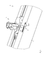
- Fig. 2 a sketch is shown to a first embodiment, wherein only a longitudinal section of the beam lamp 6 is shown in perspective; the mounting rail 1 is not shown in this figure.
- the bar light 6 has a rotary handle element 4, which is arranged between a mounting position and a contacting position movable back and forth on the profile body 2.
- Fig. 2 is the Drehabgriffs element 4 shown in the contacting position.
- the arrangement may be such that the Drehabgriffs element 4 is arranged rotatably mounted about a rotation axis D relative to the profile body 2, wherein the rotation axis D is oriented parallel to the main radiation direction R oriented.
- the design is such that the profile body 2 is not mechanically connected to the mounting rail 1, when the Drehabgriffs element 4 is in the mounting position.
- the contacting position for an electrical and mechanical connection to the Stromleitprofil provided in the support rail 1. Accordingly, in this position, contact extensions (not shown in the figures) of the rotary handle element 4 can contact the corresponding wires 11 of the current-conducting profile of the carrier rail 1.
- the Drehabgriffs element 4 in particular those in the document mentioned DE 10 2010 003 805 A1 have features shown, wherein the element in question is referred to in this document as "Drehablik".
- the rotary handle element 4 has an actuating element 41 which projects laterally from the profile body 2 with respect to the main radiation direction R. This is also in Fig. 1 recognizable.
- the terms “contacting position” and “mounting position” are also used analogously with respect to the actuating element 41.
- the actuating element 41 can thus be moved from the mounting position into the contacting position, whereby the entire Drehabgriffs element 4 is moved directly from the mounting position to the contacting position.
- the actuating element 41 is suitably fixed in position with respect to a rotation about the axis of rotation D or rotationally fixedly connected to the rest of the rotary handle element 4.
- the profile body 2 preferably has a slot 22 extending along the longitudinal axis L , through which the actuating element 41 extends, so that it can be manually moved back and forth from the outside, that is to say from the outside space A, in order to be able to move thereon Way the Drehabgriffs element 4 between the mounting position and the contacting position to move back and forth.
- the design is such that a corresponding actuation of the actuating element 41 is manually enabled from the outside, even if the beam lamp 6 is mechanically connected as intended with the mounting rail 1.
- the actuator 41 passes through the slot 22 in both the mounting position, as well as in the contacting position and also passes through the slot 22 on its entire path of movement between these two positions.
- the bar light 6 furthermore has a safety device 5 for securing the trimmer handle element 4 in FIG Contacting position on.
- a safety device 5 for securing the trimmer handle element 4 in FIG Contacting position on.
- the securing device 5 is preferably formed by a rotational security.
- the securing device 5 preferably comprises a latching mechanism which acts between the three-handle element 4 and the profile body 2.
- the design is advantageous in such a way that the latching mechanism acts directly on the actuating element 41.
- the locking mechanism is preferably designed to be detachable again, in particular manually detachable, to allow easy disassembly or removal of the beam lamp 6 of the mounting rail 1.
- the securing device 5 or the latching mechanism for this purpose comprises a latching element 51, which is designed and arranged such that - if no external forces act - it prevents movement of the rotary knob element 4 from the contacting position in the direction of the mounting position.
- the latching element 51 is formed for example by a spring-mounted tab.
- the latching element 51 is designed such that it blocks the movement path of the actuating element 41, without the action of external forces, so that no movement of the actuating element 41 out of the contacting position is possible.
- the locking element 51 is advantageously supported so resilient that it can be pivoted about an axis which is oriented parallel to the longitudinal axis L. To release the fuse, it is sufficient to manually deflect the locking element 51 about this axis against the spring force until the movement path of the actuating element 41 is released, so that the actuating element 41 and with this the Drehabgriffs element 4 can be moved or rotated in the mounting position ,
- the securing device 5 comprises a securing element 55, wherein the locking element 51 is formed by a part of the securing element 55.
- the beam lamp 6 is preferably designed such that the securing element 55 in longitudinal grooves of the Profile body 2 is engaged. This allows a particularly simple installation of the fuse element 55. In addition, a simple retrofitting of a corresponding beam lamp without securing device is made possible in this way.
- the shape of the securing element 55 is preferably such that it has an elongated recess 57 which corresponds to the shape of the slot 22, so that in the proposed arrangement 57 of the securing element 55 on the profile body 2, the actuating element 41, the recess 57 passes through as well as the slot 22.
- the latching element 51 and the tab is formed in a central region of the recess.
- Fig. 3 is sketched another embodiment.
- the reference numerals are used analogously below. Unless otherwise stated, the above statements apply analogously to the second embodiment.
- the actuating element 41 is designed resiliently flexible, in particular in a direction parallel to the main emission R.
- FIGS. 4A to 4F are exemplary views of the - separated from the remaining Drehabgriffs element 4 - actuating element 41 outlined in different directions.
- the actuating element 41 is expediently designed to be overall elongated, wherein it has a first end region 42, in particular the - in Fig. 4B by way of example denoted - passes through axis of rotation D and with a second end portion 44 an attack point for manual actuation of the actuating element 41 forms.
- the actuating element 41 expediently has a thin spot 43, which is located between the first end region 42 and the second end region 44 and which is formed by a reduced cross-sectional shape or by a thinning of the material.
- the safety device 5 in this embodiment comprises a shoulder surface 57, which is designed such that the actuating element 41 is resiliently engaged behind the shoulder surface 57, when the Drehabgriffs element 4 is in the contacting position.
- a shoulder surface 57 which is designed such that the actuating element 41 is resiliently engaged behind the shoulder surface 57, when the Drehabgriffs element 4 is in the contacting position.
- the shoulder surface 57 is formed on an edge region of the slot 22, for example by a contour punching.
- a particularly easy-handling operation of the actuating element 41 is made possible when the shoulder surface 57 is followed by a ramp-shaped portion 59 of the edge region of the slot 22, so that the actuating element 41, starting from the mounting position initially moved resiliently over the ramped portion 59 and then engages resiliently behind the shoulder surface 57, wherein it is then in the contacting position. To release the actuator 41 can then be lifted by appropriate bending simply over the shoulder surface 57.
- the slot 22 may be formed along the longitudinal axis L , in particular by a contour punching, wherein the edge region with the ramped portion 59 and the shoulder surface 57 is preferably formed on that longitudinal side of the slot 22 which in the Main emission direction R points.
Landscapes
- Engineering & Computer Science (AREA)
- General Engineering & Computer Science (AREA)
- Arrangement Of Elements, Cooling, Sealing, Or The Like Of Lighting Devices (AREA)
- Fastening Of Light Sources Or Lamp Holders (AREA)
Abstract
Description
- Die Erfindung betrifft eine Balkenleuchte zum mechanischen und elektrischen Anschluss an eine Tragschiene mit einem Stromleitprofil zur Stromversorgung der Balkenleuchte, sowie ein Leuchtensystem mit einer solche Balkenleuchte und einer solchen Tragschiene.
- Eine derartige Balkenleuchte ist aus der
DE 10 2010 003 805 A1 der Anmelderin bekannt. Die Balkenleuchte weist einen Profilkörper auf, an dem eine Lichtquelle in Form von LEDs angeordnet ist. Zum Anschluss an die Tragschiene weist die Balkenleuchte weiterhin einen Drehabgriff auf, der über einen seitlich vorstehenden Bedienungshebel aus einer Montageposition in eine Kontaktierungsposition bewegt werden kann. Wenn sich der Drehabgriff in der Montageposition befindet, kann der Profilkörper wie zur Verbindung vorgesehen an die Tragschiene angesetzt werden und durch eine anschließende Schwenkbewegung des Bedienungshebels lässt sich der Drehabgriff in die Kontaktierungsposition schwenken, wodurch die Balkenleuchte mechanisch und elektrisch mit der Tragschiene verbunden wird. Der Drehabgriff weist elektrische Kontaktierungsarme auf, die - in der Kontaktierungsposition - zur elektrischen Verbindung der Balkenleuchte Drähte kontaktieren, die in dem Stromleitprofil der Tragschiene verlaufen. - Bei Betrieb der Balkenleuchte kann es in der Praxis zu signifikanten Temperaturschwankungen kommen, die dazu führen, dass sich insbesondere die Drähte ausdehnen bzw. verkürzen. Wiederholte derartige Ausdehnungen und Verkürzungen können bewirken, dass die Kontaktierungsarme des Drehabgriffs derart bewegt werden, dass die Gefahr einer ungewollten Rückbewegung des Drehabgriffs in Richtung Montageposition gegeben ist und damit einhergehend die Gefahr eines ungewollten Lösens der Kontaktierung.
- Der Erfindung liegt die Aufgabe zugrunde, eine entsprechende verbesserte Balkenleuchte anzugeben. Insbesondere soll die Balkenleuchte eine erhöhte Betriebssicherheit aufweisen. Außerdem soll ein Leuchtensystem angegeben werden, das eine derartige Balkenleuchte und eine derartige Tragschiene umfasst.
- Diese Aufgabe wird gemäß der Erfindung mit den in den unabhängigen Ansprüchen angegebenen Gegenständen gelöst. Besondere Ausführungsarten der Erfindung sind in den abhängeigen Ansprüchen angegeben.
- Gemäß der Erfindung ist eine Balkenleuchte zum mechanischen und elektrischen Anschluss an eine Tragschiene mit einem Stromleitprofil zur Stromversorgung der Balkenleuchte vorgesehen, die einen Profilkörper aufweist, eine, an dem Profilkörper angeordnete Lichtquelle zur Erzeugung eines Lichts, das von der Balkenleuchte um eine Hauptabstrahlrichtung herum abgegeben wird sowie ein, zwischen einer Montageposition und einer Kontaktierungsposition hin und her bewegbar an dem Profilkörper angeordnetes Drehabgriffs-Element. Dabei ist die Gestaltung derart, dass der Profilkörper nicht mechanisch mit der Tragschiene verbunden ist, wenn sich das Drehabgriffs-Element in der Montageposition befindet; zur elektrischen Verbindung zu dem Stromleitprofil ist die Kontaktierungsposition vorgesehen. Das Drehabgriffs-Element weist zum Wechseln zwischen der Montageposition und der Kontaktierungsposition ein Betätigungselement auf, das mit Bezug auf die Hauptabstrahlrichtung seitlich von dem Profilköper absteht. Weiterhin weist die Balkenleuchte eine Sicherungseinrichtung zur Sicherung des Drehabgriff-Elements in der Kontaktierungsposition auf.
- Durch die Sicherungseinrichtung lässt sich insbesondere die Gefahr einer temperaturschwankungsbedingten Rückbewegung des Drehabgriffs-Elements in Richtung Montageposition verhindern oder zumindest verringern. Die vorgesehene elektrische Kontaktierung der Balkenleuchte an der Tragschiene ist somit besonders zuverlässig. Insgesamt wird hierdurch die Betriebssicherheit der Balkenleuchte erhöht.
- Vorzugsweise umfasst die Lichtquelle wenigstens eine LED (LED: lichtemittierende Diode), insbesondere mehrere LEDs, die parallel zu einer Längsachse des Profilkörpers angeordnet sind.
- Vorzugsweise umfasst die Sicherungseinrichtung einen Rastmechanismus, der zwischen dem Drehabgriffs-Element und dem Profilkörper wirkt. Auf diese Weise lässt sich herstellungstechnisch vergleichsweise einfach eine zuverlässige Sicherung erzielen.
- Dabei ist der Rastmechanismus vorteilhaft derart gestaltet, dass er unmittelbar an dem Betätigungselement angreift. Weiterhin vorteilhaft ist der Rastmechanismus lösbar gestaltet, insbesondere manuell lösbar. Auf diese Weise lässt sich die Balkenleuchte handhabungsfreundlich einfach wieder von der Tragschiene demontieren.
- Die Sicherungseinrichtung umfasst vorzugsweise ein Rastelement, das derart gestaltet und angeordnet ist, dass es eine Bewegung des Drehabgriffs-Elements aus der Kontaktierungsposition in Richtung auf die Montageposition verhindert. Hierdurch ist eine besonders einfach herzustellende und dabei zuverlässig wirkende Sicherung ermöglicht.
- Dabei ist das Rastelement vorteilhaft durch eine federnd gelagerte Lasche gebildet. Insbesondere ist dabei die Sicherungseinrichtung derart gestaltet, dass die Bewegung des Drehabgriffs-Elements aus der Kontaktierungsposition in Richtung auf die Montageposition durch die Lasche verhindert ist.
- Herstellungstechnisch vorteilhaft bildet dabei das Rastelement einen Teil eines Sicherungselements, wobei das Sicherungselement in Längsnuten des Profilkörpers eingerastet ist. Hierdurch ist insbesondere auch ein einfaches Nachrüsten ermöglicht.
- Vorzugsweise ist das Betätigungselement federnd biegbar, wobei die Sicherungseinrichtung eine Schulterfläche aufweist, die derart gestaltet ist, dass das Betätigungselement federnd hinter der Schulterfläche eingerastet ist, wenn sich das Drehabgriffs-Element in der Kontaktierungsposition befindet. Hierdurch lässt sich ein separates Sicherungselement einsparen.
- Weiterhin vorzugsweise weist dabei der Profilkörper einen Schlitz auf, wobei das Betätigungselement den Schlitz durchgreifend angeordnet ist und wobei die Schulterfläche an einem Randbereich des Schlitzes ausgebildet ist.
- Gemäß einem weiteren Aspekt der Erfindung ist ein Leuchtensystem vorgesehen, das eine Tragschiene und eine erfindungsgemäße Balkenleuchte umfasst, die zur mechanischen und elektrischen Verbindung mit der Tragschiene ausgebildet ist, insbesondere wie vorgesehen mit der Tragschiene verbunden ist.
- Die Erfindung wird im Folgenden anhand von Ausführungsbeispielen und mit Bezug auf die Zeichnungen näher erläutert. Es zeigen:
- Fig. 1
- eine Skizze zu einer erfindungsgemäßen Balkenleuchte, montiert an einer Tragschiene,
- Fig. 2
- eine detailliertere Skizze zu einer ersten Ausführungsform, wobei die Balkenleuchte von der Trägerschiene separiert dargestellt ist,
- Fig. 3
- eine entsprechende Skizze zu einer zweiten Ausführungsform und
- Figuren 4A bis 4F
- diverse Ansichten des separierten Betätigungselements des Drehabgriff-Elements.
-
Fig. 1 zeigt eine Skizze zu einer erfindungsgemäßen Balkenleuchte 6. Die Balkenleuchte 6 ist dazu ausgebildet, mechanisch und elektrisch an eine insbesondere profilartig, beispielsweise etwa U-förmig gestaltete Tragschiene 1 angeschlossen zu werden, die ein Stromleitprofil zur Stromversorgung der Balkenleuchte 6 aufweist. Das Stromleitprofil umfasst - inFig. 1 lediglich angedeutete - Drähte 11, die sich längs der Tragschiene 1, insbesondere an einem innenliegenden Wandbereich der Tragschiene 1 erstrecken. Soweit im Folgenden nicht anders dargestellt, können die Tragschiene 1 und die Balkenleuchte 6 der Beschreibung in derDE 10 2010 003 805 A1 entsprechen. - Die Balkenleuchte 6 umfasst einen Profilkörper 2, beispielsweise aus Aluminium, der insbesondere ein Gehäuse der Balkenleuchte 6 bilden kann. Der Profilkörper 2 kann - wie in
Fig. 1 beispielhaft gezeigt - im Wesentlichen einen H-förmigen Querschnitt aufweisen. Der Profilkörper 2 erstreckt sich längs einer Längsachse L, die insbesondere parallel zu der Tragschiene 1 orientiert sein kann, wenn die Balkenleuchte 6 wie vorgesehen an der Tragschiene 1 montiert ist. - Weiterhin umfasst die Balkenleuchte eine Lichtquelle 3, insbesondere in Form mehrerer LEDs, die an dem Profilkörper 2 angeordnet ist. Die LEDs sind vorzugsweise längs bzw. parallel zu der Längsachse L angeordnet. Die Lichtquelle 4 ist zur Erzeugung eines Lichts ausgestaltet, das von der Balkenleuchte 6 um eine Hauptabstrahlrichtung R herum abgegeben wird. Hierzu kann die Balkenleuchte 6 insbesondere ein entsprechendes Lichtbeeinflussungselement 61 aufweisen, das insbesondere zwischen der Lichtquelle 4 und einem Außenraum A der Balkenleuchte 6 angeordnet ist.
- In
Fig. 2 ist eine Skizze zu einem ersten Ausführungsbeispiel gezeigt, wobei lediglich ein Längsausschnitt der Balkenleuchte 6 perspektivisch gezeigt ist; die Tragschiene 1 ist in dieser Figur nicht gezeigt. - Die Balkenleuchte 6 weist ein Drehabgriffs-Element 4 auf, das zwischen einer Montageposition und einer Kontaktierungsposition hin und her bewegbar an dem Profilkörper 2 angeordnet ist. In
Fig. 2 ist das Drehabgriffs-Element 4 in der Kontaktierungsposition gezeigt. Insbesondere kann die Anordnung derart sein, dass das Drehabgriffs-Element 4 um eine Drehachse D drehbar relativ zu dem Profilkörper 2 gelagert angeordnet ist, wobei die Drehachse D parallel zu der Hauptabstrahlrichtung R orientiert verläuft. - Die Gestaltung ist dabei derart, dass der Profilkörper 2 nicht mechanisch mit der Tragschiene 1 verbunden ist, wenn sich das Drehabgriffs-Element 4 in der Montageposition befindet. Die Kontaktierungsposition für eine elektrische und auch mechanische Verbindung zu dem Stromleitprofil in der Tragschiene 1 vorgesehen. In dieser Position können dementsprechend (in den Figuren nicht gezeigte) Kontaktfortsätze des Drehabgriffs-Elements 4 die entsprechenden Drähte 11 des Stromleitprofils der Tragschiene 1 kontaktieren. Insoweit kann das Drehabgriffs-Element 4 insbesondere die in der genannten Schrift
DE 10 2010 003 805 A1 dargestellten Merkmale aufweisen, wobei das betreffende Element in dieser Schrift als "Drehabgriff" bezeichnet ist. - Zum Wechseln zwischen der Montageposition und der Kontaktierungsposition weist das Drehabgriffs-Element 4 ein Betätigungselement 41 auf, das mit Bezug auf die Hauptabstrahlrichtung R seitlich von dem Profilköper 2 absteht. Dies ist auch in
Fig. 1 erkennbar. Im Folgenden werden die Bezeichnungen "Kontaktierungsposition" und "Montageposition" analog auch mit Bezug auf das Betätigungselement 41 gebraucht. Das Betätigungselement 41 kann also aus der Montageposition in die Kontaktierungsposition bewegt werden, wodurch unmittelbar das gesamte Drehabgriffs-Element 4 aus der Montageposition in die Kontaktierungsposition bewegt wird. Das Betätigungselement 41 ist dementsprechend zweckmäßig mit Bezug auf eine Drehung um die Drehachse D lagefest bzw. drehfest mit dem restlichen Drehabgriffs-Element 4 verbunden. - Der Profilkörper 2 weist dabei vorzugsweise einen, sich längs der Längsachse L erstreckenden Schlitz 22 auf, durch den hindurch sich das Betätigungselement 41 erstreckt, so dass es von außen, also vom Außenraum A aus, manuell hin- und her bewegbar ist, um auf diese Weise das Drehabgriffs-Element 4 zwischen der Montageposition und der Kontaktierungsposition hin und her zu bewegen. Insbesondere ist die Gestaltung dabei derart, dass eine entsprechende Betätigung des Betätigungselements 41 manuell von außen ermöglicht ist, auch wenn die Balkenleuchte 6 wie vorgesehen mit der Tragschiene 1 mechanisch verbunden ist. Das Betätigungselement 41 durchsetzt dabei den Schlitz 22 sowohl in der Montageposition, als auch in der Kontaktierungsposition und durchsetzt auch auf seinem gesamten Bewegungspfad zwischen diesen beiden Positionen den Schlitz 22.
- Um zu verhindern, dass sich das Drehabgriffs-Element 4 ungewollt aus der Kontaktierungsposition heraus in Richtung Montageposition bewegt, so dass die Gefahr eines Lösens der vorgesehenen elektrischen Kontaktierung entsteht, weist die Balkenleuchte 6 weiterhin eine Sicherungseinrichtung 5 zur Sicherung des Drehabgriff-Elements 4 in der Kontaktierungsposition auf. Durch diese Sicherungseinrichtung 5 lässt sich erzielen, dass das Drehabgriffs-Element 4 in der Kontaktierungsposition verbleibt, insbesondere auch im Fall von stärkeren Temperaturschwankungen und den damit einhergehenden Formänderungen der Bauteile der Tragschiene 1 und der Balkenleuchte 6.
- Wenn das Drehabgriffs-Element 4 drehbar gelagert ist, ist die Sicherungseinrichtung 5 vorzugsweise durch eine Rotationssicherung gebildet.
- Die Sicherungseinrichtung 5 umfasst vorzugsweise einen Rastmechanismus, der zwischen dem Drehabgriffs-Element 4 und dem Profilkörper 2 wirkt. Vorteilhaft ist die Gestaltung dabei derart, dass der Rastmechanismus unmittelbar an dem Betätigungselement 41 angreift. Außerdem ist der Rastmechanismus vorzugsweise wieder lösbar gestaltet, insbesondere manuell lösbar, um eine einfache Demontage bzw. ein Abnehmen der Balkenleuchte 6 von der Tragschiene 1 zu ermöglichen.
- Bei der in
Fig. 2 gezeigten Ausführungsform umfasst die Sicherungseinrichtung 5 bzw. der Rastmechanismus hierzu ein Rastelement 51, das derart gestaltet und angeordnet ist, dass es - wenn keine äußeren Kräfte wirken - eine Bewegung des Drehabgriffs-Elements 4 aus der Kontaktierungsposition in Richtung auf die Montageposition verhindert. Das Rastelement 51 ist beispielsweise durch eine federnd gelagerte Lasche gebildet. Im gezeigten Beispiel ist das Rastelement 51 derart gestaltet, dass es - ohne Einwirkung äußerer Kräfte - den Bewegungspfad des Betätigungselements 41 versperrt, so dass keine Bewegung des Betätigungselements 41 aus der Kontaktierungsposition heraus möglich ist. - Das Rastelement 51 ist dabei vorteilhaft derart federnd gelagert, dass es um eine Achse, die parallel zu der Längsachse L orientiert verläuft geschwenkt werden kann. Zum Lösen der Sicherung genügt es, das Rastelement 51 manuell um diese Achse gegen die Federkraft auszulenken, bis der Bewegungspfad des Betätigungselements 41 freigegeben ist, so dass das Betätigungselement 41 und mit diesem das Drehabgriffs-Element 4 in die Montageposition bewegt bzw. gedreht werden kann.
- Herstellungstechnisch vorteilhaft umfasst bei der gezeigten Ausführung die Sicherungseinrichtung 5 ein Sicherungselement 55, wobei das Rastelement 51 durch einen Teil des Sicherungselements 55 gebildet ist. Die Balkenleuchte 6 ist dabei vorzugsweise derart gestaltet, dass das Sicherungselement 55 in Längsnuten des Profilkörpers 2 eingerastet ist. Dies ermöglicht eine besonders einfache Montage des Sicherungselements 55. Außerdem ist auf diese Weise eine einfache Nachrüstung einer entsprechenden Balkenleuchte ohne Sicherungseinrichtung ermöglicht.
- Die Form des Sicherungselements 55 ist dabei vorzugsweise derart, dass es eine längliche Ausnehmung 57 aufweist, die mit der Form des Schlitzes 22 korrespondiert, so dass in der vorgesehenen Anordnung 57 des Sicherungselements 55 an dem Profilkörper 2 das Betätigungselement 41 die Ausnehmung 57 ebenso durchsetzt wie den Schlitz 22. Das Rastelement 51 bzw. die Lasche ist dabei in einem mittleren Bereich der Ausnehmung ausgebildet.
- In
Fig. 3 ist ein weiteres Ausführungsbeispiel skizziert. Die Bezugszeichen sind im Folgenden analog gebraucht. Soweit nicht anders dargestellt, gelten die obigen Ausführungen auch in analoger Weise für das zweite Ausführungsbeispiel. - Bei dieser Ausführungsform ist das Betätigungselement 41 federnd biegbar gestaltet, insbesondere in einer Richtung parallel zu der Hauptabstrahlrichtung R. In den
Figuren 4A bis 4F sind beispielhaft Ansichten des - von dem restlichen Drehabgriffs-Element 4 separierten - Betätigungselements 41 aus unterschiedlichen Richtungen skizziert. Zur Erzielung der Biegbarkeit ist das Betätigungselement 41 zweckmäßig insgesamt länglich gestaltet, wobei es mit einem ersten Endbereich 42 insbesondere die - inFig. 4B beispielhaft bezeichnete - Drehachse D durchsetzt und mit einem zweiten Endbereich 44 eine Angriffsstelle zur manuellen Betätigung des Betätigungselements 41 bildet. Zur Erzielung der Biegbarkeit weist das Betätigungselement 41 zweckmäßig eine Dünnstelle 43 auf, die sich zwischen dem ersten Endbereich 42 und dem zweiten Endbereich 44 befindet und die durch eine reduzierte Querschnittform bzw. durch eine Materialverdünnung gebildet ist. - Die Sicherungseinrichtung 5 umfasst bei dieser Ausführung eine Schulterfläche 57, die derart gestaltet ist, dass das Betätigungselement 41 federnd hinter der Schulterfläche 57 eingerastet ist, wenn sich das Drehabgriffs-Element 4 in der Kontaktierungsposition befindet. Bei dieser Ausgestaltung ist im Unterschied zu der oben genannten ersten Ausführungsform kein separates Sicherungselement erforderlich. Es lassen sich somit also ein Bauteil und ein entsprechender Produktionsschritt einsparen.
- Vorteilhaft ist die Schulterfläche 57 an einem Randbereich des Schlitzes 22 ausgebildet, beispielsweise durch eine Kontur-Stanzung. Eine besonders handhabungsfreundliche Betätigung des Betätigungselements 41 ist dabei ermöglicht, wenn sich an die Schulterfläche 57 ein rampenförmiger Abschnitt 59 des Randbereichs des Schlitzes 22 anschließt, so dass das Betätigungselement 41, ausgehend von der Montageposition zunächst federnd auslenkend über den rampenförmigen Abschnitt 59 bewegt wird und anschließend hinter die Schulterfläche 57 federnd eingreift, wobei es sich dann in der Kontaktierungsposition befindet. Zum Lösen kann dann das Betätigungselement 41 durch entsprechendes Biegen einfach über die Schulterfläche 57 gehoben werden.
- Wie im gezeigten Beispiel der Fall, kann der Schlitz 22 längs der Längsachse L ausgebildet sein, insbesondere durch eine Kontur-Stanzung, wobei der Randbereich mit dem rampenförmigen Abschnitt 59 und der Schulterfläche 57 vorzugsweise auf derjenigen Längsseite des Schlitzes 22 ausgebildet ist, die in die Hauptabstrahlrichtung R weist.
Claims (12)
- Balkenleuchte zum mechanischen und elektrischen Anschluss an eine Tragschiene (1) mit einem Stromleitprofil zur Stromversorgung der Balkenleuchte, aufweisend- einen Profilkörper (2),- eine, an dem Profilkörper (2) angeordnete Lichtquelle (3) zur Erzeugung eines Lichts, das von der Balkenleuchte um eine Hauptabstrahlrichtung (R) herum abgegeben wird,- ein, zwischen einer Montageposition und einer Kontaktierungsposition hin und her bewegbar an dem Profilkörper (2) angeordnetes Drehabgriffs-Element (4), wobei der Profilkörper (2) nicht mechanisch mit der Tragschiene (1) verbunden ist, wenn sich das Drehabgriffs-Element (4) in der Montageposition befindet und zur elektrischen Verbindung zu dem Stromleitprofil die Kontaktierungsposition vorgesehen ist,
wobei das Drehabgriffs-Element (4) zum Wechseln zwischen der Montageposition und der Kontaktierungsposition ein Betätigungselement (41) aufweist, das mit Bezug auf die Hauptabstrahlrichtung (R) seitlich von dem Profilköper (2) absteht,
gekennzeichnet durch
eine Sicherungseinrichtung (5) zur Sicherung des Drehabgriff-Elements (4) in der Kontaktierungsposition. - Balkenleuchte nach Anspruch 1,
bei der die Lichtquelle (4) wenigstens eine LED umfasst, vorzugsweise mehrere LEDs, die parallel zu einer Längsachse des Profilkörpers (2) angeordnet sind. - Balkenleuchte nach Anspruch 1 oder 2,
bei der die Sicherungseinrichtung (5) einen Rastmechanismus umfasst, der zwischen dem Drehabgriffs-Element (4) und dem Profilkörper (2) wirkt. - Balkenleuchte nach Anspruch 3,
bei der der Rastmechanismus derart gestaltet ist, dass er unmittelbar an dem Betätigungselement (41) angreift. - Balkenleuchte nach Anspruch 3 oder 4,
bei der der Rastmechanismus lösbar gestaltet ist, insbesondere manuell lösbar. - Balkenleuchte nach einem der vorhergehenden Ansprüche,
bei der die Sicherungseinrichtung (5) ein Rastelement (51) umfasst, das derart gestaltet und angeordnet ist, dass es eine Bewegung des Drehabgriffs-Elements (4) aus der Kontaktierungsposition in Richtung auf die Montageposition verhindert. - Balkenleuchte nach Anspruch 6,
bei der das Rastelement (51) durch eine federnd gelagerte Lasche gebildet ist. - Balkenleuchte nach Anspruch 7,
bei der die Sicherungseinrichtung (5) derart gestaltet ist, dass die Bewegung des Drehabgriffs-Elements (41) aus der Kontaktierungsposition in Richtung auf die Montageposition durch die Lasche verhindert ist. - Balkenleuchte nach einem der Ansprüche 6 bis 8,
bei der das Rastelement (51) einen Teil eines Sicherungselements (55) bildet, wobei das Sicherungselement (55) in Längsnuten des Profilkörpers (2) eingerastet ist. - Balkenleuchte nach einem der vorhergehenden Ansprüche,
bei der das Betätigungselement (41) federnd biegbar ist und die Sicherungseinrichtung (5) eine Schulterfläche (57) aufweist, die derart gestaltet ist, dass das Betätigungselement (41) federnd hinter der Schulterfläche (57) eingerastet ist, wenn sich das Drehabgriffs-Element (4) in der Kontaktierungsposition befindet. - Balkenleuchte nach Anspruch 10,
bei der der Profilkörper (2) einen Schlitz (22) aufweist und das Betätigungselement (41) den Schlitz (22) durchgreifend angeordnet ist, wobei die Schulterfläche (57) an einem Randbereich des Schlitzes (22) ausgebildet ist. - Leuchtensystem, aufweisend- eine Tragschiene (1) und- eine Balkenleuchte (6) nach einem der vorhergehenden Ansprüche, die zur mechanischen und elektrischen Verbindung mit der Tragschiene (1) ausgebildet ist, insbesondere wie vorgesehen mit der Tragschiene (1) verbunden ist.
Applications Claiming Priority (1)
| Application Number | Priority Date | Filing Date | Title |
|---|---|---|---|
| DE202012100629U DE202012100629U1 (de) | 2012-02-24 | 2012-02-24 | Balkenleuchte zum mechanischen und elektrischen Anschluss an eine Tragschiene |
Publications (2)
| Publication Number | Publication Date |
|---|---|
| EP2631532A1 true EP2631532A1 (de) | 2013-08-28 |
| EP2631532B1 EP2631532B1 (de) | 2015-05-20 |
Family
ID=47748468
Family Applications (1)
| Application Number | Title | Priority Date | Filing Date |
|---|---|---|---|
| EP20130155772 Active EP2631532B1 (de) | 2012-02-24 | 2013-02-19 | Balkenleuchte zum mechanischen und elektrischen Anschluss an eine Tragschiene |
Country Status (2)
| Country | Link |
|---|---|
| EP (1) | EP2631532B1 (de) |
| DE (1) | DE202012100629U1 (de) |
Cited By (1)
| Publication number | Priority date | Publication date | Assignee | Title |
|---|---|---|---|---|
| WO2025153432A1 (de) | 2024-01-19 | 2025-07-24 | Zumtobel Lighting Gmbh | ELEKTRISCHES MODUL ZUM ANSCHLIEßEN AN EINE TRAGSCHIENE MIT EINEM TRAGSCHIENENPROFIL |
Families Citing this family (11)
| Publication number | Priority date | Publication date | Assignee | Title |
|---|---|---|---|---|
| EP2908388A1 (de) * | 2014-02-14 | 2015-08-19 | Universal Electric Corporation | Werkzeuglose Busweg-Abnahmevorrichtung für elektrischen Busweg und Installationsverfahren |
| DE202014104800U1 (de) * | 2014-10-07 | 2016-01-11 | Zumtobel Lighting Gmbh | LED-Leuchte mit verstellbarem Halteelement sowie Anordnung zur Lichtabgabe mit einer solchen LED-Leuchte |
| DE102015109998B4 (de) * | 2015-06-22 | 2017-03-23 | Siteco Beleuchtungstechnik Gmbh | Leuchteneinsatz mit Drehriegel |
| ITUB20155446A1 (it) * | 2015-11-11 | 2017-05-11 | Innovazione Srls | Sistema di illuminazione integrato nelle strutture portanti del cartongesso |
| CN105972563B (zh) * | 2016-06-06 | 2022-07-05 | 深圳亚锐光电科技有限公司 | 导电导轨接驳结构、导轨式导电装置以及条形灯照明装置 |
| CN109237361B (zh) * | 2018-10-15 | 2021-01-22 | 中车长春轨道客车股份有限公司 | 灯架及测试灯 |
| DE202019105531U1 (de) * | 2019-10-08 | 2021-01-20 | Zumtobel Lighting Gmbh | Leuchte oder elektrische Einheit zum Anschluss an eine Tragschiene |
| DE102020128275A1 (de) * | 2020-10-28 | 2022-04-28 | Zumtobel Lighting Gmbh | Elektrisches modul zum anschluss an eine tragschiene |
| DE102021112403A1 (de) | 2021-05-12 | 2022-11-17 | Zumtobel Lighting Gmbh | Elektrisches Modul zum Anschließen an eine Tragschiene |
| CN218599527U (zh) * | 2022-11-01 | 2023-03-10 | 欧普照明股份有限公司 | 轨道灯 |
| DE102023110440B4 (de) * | 2023-04-24 | 2025-01-09 | H4X e. U. | Befestigungsanordnung zum Befestigen einer Leuchtbaugruppe sowie Beleuchtungsvorrichtung mit mindestens einer derartigen Befestigungsanordnung |
Citations (4)
| Publication number | Priority date | Publication date | Assignee | Title |
|---|---|---|---|---|
| DE4312888A1 (de) * | 1993-04-20 | 1994-10-27 | Siemens Ag | Steckverbindung für eine Lichtbandanordnung |
| EP1473807A1 (de) * | 2003-04-30 | 2004-11-03 | Zumtobel Staff GmbH | Stromschienensystem für Leuchten und Verriegelungselement |
| EP2113716A1 (de) * | 2008-04-29 | 2009-11-04 | BTICINO S.p.A. | Einbauleuchte für den Einbau in eine aufgehängte Stromverteilungsbahn |
| DE102010003805A1 (de) | 2010-04-09 | 2011-10-13 | Zumtobel Lighting Gmbh | Leuchte mit LEDs und den LEDs zugeordneten Linsen |
Family Cites Families (3)
| Publication number | Priority date | Publication date | Assignee | Title |
|---|---|---|---|---|
| DE4300402C2 (de) * | 1993-01-09 | 1994-10-13 | Erco Leuchten | Adapter zur lösbaren Halterung in einer Stromschiene |
| JP2007084033A (ja) * | 2005-08-25 | 2007-04-05 | Tsuda Industries Co Ltd | シフトレバー装置 |
| DE102008011707B4 (de) * | 2008-02-28 | 2010-04-08 | Sinitec Vertriebsgesellschaft Mbh | Gehäuse mit einem Schiebeschalter |
-
2012
- 2012-02-24 DE DE202012100629U patent/DE202012100629U1/de not_active Expired - Lifetime
-
2013
- 2013-02-19 EP EP20130155772 patent/EP2631532B1/de active Active
Patent Citations (4)
| Publication number | Priority date | Publication date | Assignee | Title |
|---|---|---|---|---|
| DE4312888A1 (de) * | 1993-04-20 | 1994-10-27 | Siemens Ag | Steckverbindung für eine Lichtbandanordnung |
| EP1473807A1 (de) * | 2003-04-30 | 2004-11-03 | Zumtobel Staff GmbH | Stromschienensystem für Leuchten und Verriegelungselement |
| EP2113716A1 (de) * | 2008-04-29 | 2009-11-04 | BTICINO S.p.A. | Einbauleuchte für den Einbau in eine aufgehängte Stromverteilungsbahn |
| DE102010003805A1 (de) | 2010-04-09 | 2011-10-13 | Zumtobel Lighting Gmbh | Leuchte mit LEDs und den LEDs zugeordneten Linsen |
Cited By (1)
| Publication number | Priority date | Publication date | Assignee | Title |
|---|---|---|---|---|
| WO2025153432A1 (de) | 2024-01-19 | 2025-07-24 | Zumtobel Lighting Gmbh | ELEKTRISCHES MODUL ZUM ANSCHLIEßEN AN EINE TRAGSCHIENE MIT EINEM TRAGSCHIENENPROFIL |
Also Published As
| Publication number | Publication date |
|---|---|
| EP2631532B1 (de) | 2015-05-20 |
| DE202012100629U1 (de) | 2013-05-27 |
Similar Documents
| Publication | Publication Date | Title |
|---|---|---|
| EP2631532B1 (de) | Balkenleuchte zum mechanischen und elektrischen Anschluss an eine Tragschiene | |
| EP2375128B1 (de) | Leuchte mit LEDs und den LEDs zugeordneten Linsen | |
| EP2735787B1 (de) | Einbauleuchte | |
| EP2748514B1 (de) | Leuchteneinheit für eine leuchte, sowie leuchte | |
| EP3014169B1 (de) | Leuchte zur verwendung in einem lichtbandsystem sowie lichtbandsystem | |
| EP2890926B1 (de) | Anordnung zur lichtabgabe mit mehreren led-platinen | |
| EP4063725A1 (de) | Adapter für eine beleuchtungsanordnung | |
| EP3006819B1 (de) | Led-leuchte mit verstellbarem halteelement sowie anordnung zur lichtabgabe mit einer solchen led-leuchte | |
| DE102021102477A1 (de) | Leiteranschlussklemme | |
| EP4273446A1 (de) | Befestigungseinrichtung zum befestigen einer leuchtbaugruppe sowie beleuchtungsanordnung mit mindestens einer derartigen befestigungseinrichtung | |
| WO2014090744A1 (de) | Einbauleuchte | |
| EP0235350A2 (de) | Schalter, insbesondere für Kraftfahrzeuge | |
| EP3006818A1 (de) | Längliche led-leuchte | |
| DE3343661A1 (de) | Elektrischer schalter | |
| AT513724B1 (de) | Vorrichtung zum Festlegen einer Lampe | |
| DE112013001541T5 (de) | Anschlussverbindungsstruktur und Fahrzeuginnenraumleuchte | |
| EP2711622B1 (de) | Leuchte mit Berührschutz | |
| EP2833050B1 (de) | Pendelleuchte mit einer Lichtquelle zur Erzeugung einer indirekten Beleuchtung | |
| WO2008061596A1 (de) | Staubschutzeinrichtung für ein melde- und/oder befehlsgerät | |
| DE6803358U (de) | Elektrisches bauelement variablen widerstandes | |
| WO2026073648A2 (de) | Anordnung zum verbinden von tragprofilen eines leuchtentragschienensystems | |
| DE102018007036A1 (de) | Vorrichtung zur elektrischen Verbindung | |
| AT14446U1 (de) | Lichtbandsystem | |
| EP3062398A1 (de) | Kochfeldvorrichtung | |
| DE202012005899U1 (de) | Beleuchtungsvorrichtung |
Legal Events
| Date | Code | Title | Description |
|---|---|---|---|
| PUAI | Public reference made under article 153(3) epc to a published international application that has entered the european phase |
Free format text: ORIGINAL CODE: 0009012 |
|
| AK | Designated contracting states |
Kind code of ref document: A1 Designated state(s): AL AT BE BG CH CY CZ DE DK EE ES FI FR GB GR HR HU IE IS IT LI LT LU LV MC MK MT NL NO PL PT RO RS SE SI SK SM TR |
|
| AX | Request for extension of the european patent |
Extension state: BA ME |
|
| 17P | Request for examination filed |
Effective date: 20140207 |
|
| RBV | Designated contracting states (corrected) |
Designated state(s): AL AT BE BG CH CY CZ DE DK EE ES FI FR GB GR HR HU IE IS IT LI LT LU LV MC MK MT NL NO PL PT RO RS SE SI SK SM TR |
|
| RIC1 | Information provided on ipc code assigned before grant |
Ipc: H01R 25/16 20060101ALI20140724BHEP Ipc: F21V 21/02 20060101ALI20140724BHEP Ipc: F21S 4/00 20060101AFI20140724BHEP Ipc: H01R 25/14 20060101ALI20140724BHEP Ipc: F21Y 103/00 20060101ALN20140724BHEP Ipc: F21S 8/00 20060101ALI20140724BHEP |
|
| GRAP | Despatch of communication of intention to grant a patent |
Free format text: ORIGINAL CODE: EPIDOSNIGR1 |
|
| INTG | Intention to grant announced |
Effective date: 20140922 |
|
| GRAS | Grant fee paid |
Free format text: ORIGINAL CODE: EPIDOSNIGR3 |
|
| GRAA | (expected) grant |
Free format text: ORIGINAL CODE: 0009210 |
|
| AK | Designated contracting states |
Kind code of ref document: B1 Designated state(s): AL AT BE BG CH CY CZ DE DK EE ES FI FR GB GR HR HU IE IS IT LI LT LU LV MC MK MT NL NO PL PT RO RS SE SI SK SM TR |
|
| REG | Reference to a national code |
Ref country code: GB Ref legal event code: FG4D Free format text: NOT ENGLISH |
|
| REG | Reference to a national code |
Ref country code: CH Ref legal event code: NV Representative=s name: FIAMMENGHI-FIAMMENGHI, CH Ref country code: CH Ref legal event code: EP |
|
| REG | Reference to a national code |
Ref country code: AT Ref legal event code: REF Ref document number: 727921 Country of ref document: AT Kind code of ref document: T Effective date: 20150615 |
|
| REG | Reference to a national code |
Ref country code: IE Ref legal event code: FG4D Free format text: LANGUAGE OF EP DOCUMENT: GERMAN |
|
| REG | Reference to a national code |
Ref country code: DE Ref legal event code: R096 Ref document number: 502013000663 Country of ref document: DE |
|
| REG | Reference to a national code |
Ref country code: LT Ref legal event code: MG4D |
|
| REG | Reference to a national code |
Ref country code: NL Ref legal event code: MP Effective date: 20150520 |
|
| PG25 | Lapsed in a contracting state [announced via postgrant information from national office to epo] |
Ref country code: PT Free format text: LAPSE BECAUSE OF FAILURE TO SUBMIT A TRANSLATION OF THE DESCRIPTION OR TO PAY THE FEE WITHIN THE PRESCRIBED TIME-LIMIT Effective date: 20150921 Ref country code: NO Free format text: LAPSE BECAUSE OF FAILURE TO SUBMIT A TRANSLATION OF THE DESCRIPTION OR TO PAY THE FEE WITHIN THE PRESCRIBED TIME-LIMIT Effective date: 20150820 Ref country code: FI Free format text: LAPSE BECAUSE OF FAILURE TO SUBMIT A TRANSLATION OF THE DESCRIPTION OR TO PAY THE FEE WITHIN THE PRESCRIBED TIME-LIMIT Effective date: 20150520 Ref country code: HR Free format text: LAPSE BECAUSE OF FAILURE TO SUBMIT A TRANSLATION OF THE DESCRIPTION OR TO PAY THE FEE WITHIN THE PRESCRIBED TIME-LIMIT Effective date: 20150520 Ref country code: LT Free format text: LAPSE BECAUSE OF FAILURE TO SUBMIT A TRANSLATION OF THE DESCRIPTION OR TO PAY THE FEE WITHIN THE PRESCRIBED TIME-LIMIT Effective date: 20150520 Ref country code: ES Free format text: LAPSE BECAUSE OF FAILURE TO SUBMIT A TRANSLATION OF THE DESCRIPTION OR TO PAY THE FEE WITHIN THE PRESCRIBED TIME-LIMIT Effective date: 20150520 |
|
| PG25 | Lapsed in a contracting state [announced via postgrant information from national office to epo] |
Ref country code: IS Free format text: LAPSE BECAUSE OF FAILURE TO SUBMIT A TRANSLATION OF THE DESCRIPTION OR TO PAY THE FEE WITHIN THE PRESCRIBED TIME-LIMIT Effective date: 20150920 Ref country code: LV Free format text: LAPSE BECAUSE OF FAILURE TO SUBMIT A TRANSLATION OF THE DESCRIPTION OR TO PAY THE FEE WITHIN THE PRESCRIBED TIME-LIMIT Effective date: 20150520 Ref country code: BG Free format text: LAPSE BECAUSE OF FAILURE TO SUBMIT A TRANSLATION OF THE DESCRIPTION OR TO PAY THE FEE WITHIN THE PRESCRIBED TIME-LIMIT Effective date: 20150820 Ref country code: RS Free format text: LAPSE BECAUSE OF FAILURE TO SUBMIT A TRANSLATION OF THE DESCRIPTION OR TO PAY THE FEE WITHIN THE PRESCRIBED TIME-LIMIT Effective date: 20150520 Ref country code: GR Free format text: LAPSE BECAUSE OF FAILURE TO SUBMIT A TRANSLATION OF THE DESCRIPTION OR TO PAY THE FEE WITHIN THE PRESCRIBED TIME-LIMIT Effective date: 20150821 |
|
| PG25 | Lapsed in a contracting state [announced via postgrant information from national office to epo] |
Ref country code: EE Free format text: LAPSE BECAUSE OF FAILURE TO SUBMIT A TRANSLATION OF THE DESCRIPTION OR TO PAY THE FEE WITHIN THE PRESCRIBED TIME-LIMIT Effective date: 20150520 Ref country code: DK Free format text: LAPSE BECAUSE OF FAILURE TO SUBMIT A TRANSLATION OF THE DESCRIPTION OR TO PAY THE FEE WITHIN THE PRESCRIBED TIME-LIMIT Effective date: 20150520 |
|
| REG | Reference to a national code |
Ref country code: DE Ref legal event code: R097 Ref document number: 502013000663 Country of ref document: DE |
|
| PG25 | Lapsed in a contracting state [announced via postgrant information from national office to epo] |
Ref country code: RO Free format text: LAPSE BECAUSE OF NON-PAYMENT OF DUE FEES Effective date: 20150520 Ref country code: PL Free format text: LAPSE BECAUSE OF FAILURE TO SUBMIT A TRANSLATION OF THE DESCRIPTION OR TO PAY THE FEE WITHIN THE PRESCRIBED TIME-LIMIT Effective date: 20150520 Ref country code: SK Free format text: LAPSE BECAUSE OF FAILURE TO SUBMIT A TRANSLATION OF THE DESCRIPTION OR TO PAY THE FEE WITHIN THE PRESCRIBED TIME-LIMIT Effective date: 20150520 Ref country code: CZ Free format text: LAPSE BECAUSE OF FAILURE TO SUBMIT A TRANSLATION OF THE DESCRIPTION OR TO PAY THE FEE WITHIN THE PRESCRIBED TIME-LIMIT Effective date: 20150520 |
|
| REG | Reference to a national code |
Ref country code: FR Ref legal event code: PLFP Year of fee payment: 4 |
|
| PLBE | No opposition filed within time limit |
Free format text: ORIGINAL CODE: 0009261 |
|
| STAA | Information on the status of an ep patent application or granted ep patent |
Free format text: STATUS: NO OPPOSITION FILED WITHIN TIME LIMIT |
|
| 26N | No opposition filed |
Effective date: 20160223 |
|
| PG25 | Lapsed in a contracting state [announced via postgrant information from national office to epo] |
Ref country code: SI Free format text: LAPSE BECAUSE OF FAILURE TO SUBMIT A TRANSLATION OF THE DESCRIPTION OR TO PAY THE FEE WITHIN THE PRESCRIBED TIME-LIMIT Effective date: 20150520 Ref country code: BE Free format text: LAPSE BECAUSE OF NON-PAYMENT OF DUE FEES Effective date: 20160229 |
|
| PG25 | Lapsed in a contracting state [announced via postgrant information from national office to epo] |
Ref country code: MC Free format text: LAPSE BECAUSE OF FAILURE TO SUBMIT A TRANSLATION OF THE DESCRIPTION OR TO PAY THE FEE WITHIN THE PRESCRIBED TIME-LIMIT Effective date: 20150520 Ref country code: LU Free format text: LAPSE BECAUSE OF FAILURE TO SUBMIT A TRANSLATION OF THE DESCRIPTION OR TO PAY THE FEE WITHIN THE PRESCRIBED TIME-LIMIT Effective date: 20160219 |
|
| REG | Reference to a national code |
Ref country code: IE Ref legal event code: MM4A |
|
| PG25 | Lapsed in a contracting state [announced via postgrant information from national office to epo] |
Ref country code: IE Free format text: LAPSE BECAUSE OF NON-PAYMENT OF DUE FEES Effective date: 20160219 |
|
| REG | Reference to a national code |
Ref country code: FR Ref legal event code: PLFP Year of fee payment: 5 |
|
| PG25 | Lapsed in a contracting state [announced via postgrant information from national office to epo] |
Ref country code: NL Free format text: LAPSE BECAUSE OF FAILURE TO SUBMIT A TRANSLATION OF THE DESCRIPTION OR TO PAY THE FEE WITHIN THE PRESCRIBED TIME-LIMIT Effective date: 20150520 Ref country code: SE Free format text: LAPSE BECAUSE OF FAILURE TO SUBMIT A TRANSLATION OF THE DESCRIPTION OR TO PAY THE FEE WITHIN THE PRESCRIBED TIME-LIMIT Effective date: 20150520 |
|
| PG25 | Lapsed in a contracting state [announced via postgrant information from national office to epo] |
Ref country code: MT Free format text: LAPSE BECAUSE OF FAILURE TO SUBMIT A TRANSLATION OF THE DESCRIPTION OR TO PAY THE FEE WITHIN THE PRESCRIBED TIME-LIMIT Effective date: 20150520 |
|
| REG | Reference to a national code |
Ref country code: FR Ref legal event code: PLFP Year of fee payment: 6 |
|
| PG25 | Lapsed in a contracting state [announced via postgrant information from national office to epo] |
Ref country code: SM Free format text: LAPSE BECAUSE OF FAILURE TO SUBMIT A TRANSLATION OF THE DESCRIPTION OR TO PAY THE FEE WITHIN THE PRESCRIBED TIME-LIMIT Effective date: 20150520 Ref country code: HU Free format text: LAPSE BECAUSE OF FAILURE TO SUBMIT A TRANSLATION OF THE DESCRIPTION OR TO PAY THE FEE WITHIN THE PRESCRIBED TIME-LIMIT; INVALID AB INITIO Effective date: 20130219 Ref country code: CY Free format text: LAPSE BECAUSE OF FAILURE TO SUBMIT A TRANSLATION OF THE DESCRIPTION OR TO PAY THE FEE WITHIN THE PRESCRIBED TIME-LIMIT Effective date: 20150520 |
|
| PG25 | Lapsed in a contracting state [announced via postgrant information from national office to epo] |
Ref country code: TR Free format text: LAPSE BECAUSE OF FAILURE TO SUBMIT A TRANSLATION OF THE DESCRIPTION OR TO PAY THE FEE WITHIN THE PRESCRIBED TIME-LIMIT Effective date: 20150520 Ref country code: MK Free format text: LAPSE BECAUSE OF FAILURE TO SUBMIT A TRANSLATION OF THE DESCRIPTION OR TO PAY THE FEE WITHIN THE PRESCRIBED TIME-LIMIT Effective date: 20150520 |
|
| PG25 | Lapsed in a contracting state [announced via postgrant information from national office to epo] |
Ref country code: AL Free format text: LAPSE BECAUSE OF FAILURE TO SUBMIT A TRANSLATION OF THE DESCRIPTION OR TO PAY THE FEE WITHIN THE PRESCRIBED TIME-LIMIT Effective date: 20150520 |
|
| PGFP | Annual fee paid to national office [announced via postgrant information from national office to epo] |
Ref country code: IT Payment date: 20220221 Year of fee payment: 10 |
|
| P01 | Opt-out of the competence of the unified patent court (upc) registered |
Effective date: 20230530 |
|
| PGFP | Annual fee paid to national office [announced via postgrant information from national office to epo] |
Ref country code: AT Payment date: 20230530 Year of fee payment: 11 |
|
| PG25 | Lapsed in a contracting state [announced via postgrant information from national office to epo] |
Ref country code: IT Free format text: LAPSE BECAUSE OF NON-PAYMENT OF DUE FEES Effective date: 20230219 |
|
| REG | Reference to a national code |
Ref country code: AT Ref legal event code: MM01 Ref document number: 727921 Country of ref document: AT Kind code of ref document: T Effective date: 20240219 |
|
| PG25 | Lapsed in a contracting state [announced via postgrant information from national office to epo] |
Ref country code: AT Free format text: LAPSE BECAUSE OF NON-PAYMENT OF DUE FEES Effective date: 20240219 |
|
| PG25 | Lapsed in a contracting state [announced via postgrant information from national office to epo] |
Ref country code: AT Free format text: LAPSE BECAUSE OF NON-PAYMENT OF DUE FEES Effective date: 20240219 |
|
| REG | Reference to a national code |
Ref country code: CH Ref legal event code: U11 Free format text: ST27 STATUS EVENT CODE: U-0-0-U10-U11 (AS PROVIDED BY THE NATIONAL OFFICE) Effective date: 20260301 |
|
| PGFP | Annual fee paid to national office [announced via postgrant information from national office to epo] |
Ref country code: GB Payment date: 20260223 Year of fee payment: 14 |
|
| PGFP | Annual fee paid to national office [announced via postgrant information from national office to epo] |
Ref country code: DE Payment date: 20260220 Year of fee payment: 14 |
|
| PGFP | Annual fee paid to national office [announced via postgrant information from national office to epo] |
Ref country code: FR Payment date: 20260224 Year of fee payment: 14 |
|
| PGFP | Annual fee paid to national office [announced via postgrant information from national office to epo] |
Ref country code: CH Payment date: 20260301 Year of fee payment: 14 |