EP2630983A1 - Fluidkupplung mit mehreren radial beweglichen Steckelementen - Google Patents
Fluidkupplung mit mehreren radial beweglichen Steckelementen Download PDFInfo
- Publication number
- EP2630983A1 EP2630983A1 EP12156560.0A EP12156560A EP2630983A1 EP 2630983 A1 EP2630983 A1 EP 2630983A1 EP 12156560 A EP12156560 A EP 12156560A EP 2630983 A1 EP2630983 A1 EP 2630983A1
- Authority
- EP
- European Patent Office
- Prior art keywords
- plug
- elements
- connector part
- fluid connector
- part according
- Prior art date
- Legal status (The legal status is an assumption and is not a legal conclusion. Google has not performed a legal analysis and makes no representation as to the accuracy of the status listed.)
- Granted
Links
Images

Classifications
-
- F—MECHANICAL ENGINEERING; LIGHTING; HEATING; WEAPONS; BLASTING
- F16—ENGINEERING ELEMENTS AND UNITS; GENERAL MEASURES FOR PRODUCING AND MAINTAINING EFFECTIVE FUNCTIONING OF MACHINES OR INSTALLATIONS; THERMAL INSULATION IN GENERAL
- F16L—PIPES; JOINTS OR FITTINGS FOR PIPES; SUPPORTS FOR PIPES, CABLES OR PROTECTIVE TUBING; MEANS FOR THERMAL INSULATION IN GENERAL
- F16L39/00—Joints or fittings for double-walled or multi-channel pipes or pipe assemblies
- F16L39/04—Joints or fittings for double-walled or multi-channel pipes or pipe assemblies allowing adjustment or movement
-
- F—MECHANICAL ENGINEERING; LIGHTING; HEATING; WEAPONS; BLASTING
- F16—ENGINEERING ELEMENTS AND UNITS; GENERAL MEASURES FOR PRODUCING AND MAINTAINING EFFECTIVE FUNCTIONING OF MACHINES OR INSTALLATIONS; THERMAL INSULATION IN GENERAL
- F16L—PIPES; JOINTS OR FITTINGS FOR PIPES; SUPPORTS FOR PIPES, CABLES OR PROTECTIVE TUBING; MEANS FOR THERMAL INSULATION IN GENERAL
- F16L39/00—Joints or fittings for double-walled or multi-channel pipes or pipe assemblies
-
- A—HUMAN NECESSITIES
- A61—MEDICAL OR VETERINARY SCIENCE; HYGIENE
- A61M—DEVICES FOR INTRODUCING MEDIA INTO, OR ONTO, THE BODY; DEVICES FOR TRANSDUCING BODY MEDIA OR FOR TAKING MEDIA FROM THE BODY; DEVICES FOR PRODUCING OR ENDING SLEEP OR STUPOR
- A61M39/00—Tubes, tube connectors, tube couplings, valves, access sites or the like, specially adapted for medical use
- A61M39/10—Tube connectors; Tube couplings
-
- F—MECHANICAL ENGINEERING; LIGHTING; HEATING; WEAPONS; BLASTING
- F16—ENGINEERING ELEMENTS AND UNITS; GENERAL MEASURES FOR PRODUCING AND MAINTAINING EFFECTIVE FUNCTIONING OF MACHINES OR INSTALLATIONS; THERMAL INSULATION IN GENERAL
- F16L—PIPES; JOINTS OR FITTINGS FOR PIPES; SUPPORTS FOR PIPES, CABLES OR PROTECTIVE TUBING; MEANS FOR THERMAL INSULATION IN GENERAL
- F16L21/00—Joints with sleeve or socket
- F16L21/02—Joints with sleeve or socket with elastic sealing rings between pipe and sleeve or between pipe and socket, e.g. with rolling or other prefabricated profiled rings
-
- F—MECHANICAL ENGINEERING; LIGHTING; HEATING; WEAPONS; BLASTING
- F16—ENGINEERING ELEMENTS AND UNITS; GENERAL MEASURES FOR PRODUCING AND MAINTAINING EFFECTIVE FUNCTIONING OF MACHINES OR INSTALLATIONS; THERMAL INSULATION IN GENERAL
- F16L—PIPES; JOINTS OR FITTINGS FOR PIPES; SUPPORTS FOR PIPES, CABLES OR PROTECTIVE TUBING; MEANS FOR THERMAL INSULATION IN GENERAL
- F16L37/00—Couplings of the quick-acting type
- F16L37/02—Couplings of the quick-acting type in which the connection is maintained only by friction of the parts being joined
-
- F—MECHANICAL ENGINEERING; LIGHTING; HEATING; WEAPONS; BLASTING
- F16—ENGINEERING ELEMENTS AND UNITS; GENERAL MEASURES FOR PRODUCING AND MAINTAINING EFFECTIVE FUNCTIONING OF MACHINES OR INSTALLATIONS; THERMAL INSULATION IN GENERAL
- F16L—PIPES; JOINTS OR FITTINGS FOR PIPES; SUPPORTS FOR PIPES, CABLES OR PROTECTIVE TUBING; MEANS FOR THERMAL INSULATION IN GENERAL
- F16L37/00—Couplings of the quick-acting type
- F16L37/56—Couplings of the quick-acting type for double-walled or multi-channel pipes or pipe assemblies
-
- A—HUMAN NECESSITIES
- A61—MEDICAL OR VETERINARY SCIENCE; HYGIENE
- A61B—DIAGNOSIS; SURGERY; IDENTIFICATION
- A61B18/00—Surgical instruments, devices or methods for transferring non-mechanical forms of energy to or from the body
- A61B18/02—Surgical instruments, devices or methods for transferring non-mechanical forms of energy to or from the body by cooling, e.g. cryogenic techniques
-
- A—HUMAN NECESSITIES
- A61—MEDICAL OR VETERINARY SCIENCE; HYGIENE
- A61M—DEVICES FOR INTRODUCING MEDIA INTO, OR ONTO, THE BODY; DEVICES FOR TRANSDUCING BODY MEDIA OR FOR TAKING MEDIA FROM THE BODY; DEVICES FOR PRODUCING OR ENDING SLEEP OR STUPOR
- A61M39/00—Tubes, tube connectors, tube couplings, valves, access sites or the like, specially adapted for medical use
- A61M39/10—Tube connectors; Tube couplings
- A61M2039/1044—Verifying the connection, e.g. audible feedback, tactile feedback, visual feedback, using external light sources
-
- A—HUMAN NECESSITIES
- A61—MEDICAL OR VETERINARY SCIENCE; HYGIENE
- A61M—DEVICES FOR INTRODUCING MEDIA INTO, OR ONTO, THE BODY; DEVICES FOR TRANSDUCING BODY MEDIA OR FOR TAKING MEDIA FROM THE BODY; DEVICES FOR PRODUCING OR ENDING SLEEP OR STUPOR
- A61M39/00—Tubes, tube connectors, tube couplings, valves, access sites or the like, specially adapted for medical use
- A61M39/10—Tube connectors; Tube couplings
- A61M2039/1083—Tube connectors; Tube couplings having a plurality of female connectors, e.g. Luer connectors
-
- A—HUMAN NECESSITIES
- A61—MEDICAL OR VETERINARY SCIENCE; HYGIENE
- A61M—DEVICES FOR INTRODUCING MEDIA INTO, OR ONTO, THE BODY; DEVICES FOR TRANSDUCING BODY MEDIA OR FOR TAKING MEDIA FROM THE BODY; DEVICES FOR PRODUCING OR ENDING SLEEP OR STUPOR
- A61M39/00—Tubes, tube connectors, tube couplings, valves, access sites or the like, specially adapted for medical use
- A61M39/10—Tube connectors; Tube couplings
- A61M2039/1088—Tube connectors; Tube couplings having a plurality of male connectors, e.g. Luer connectors
-
- A—HUMAN NECESSITIES
- A61—MEDICAL OR VETERINARY SCIENCE; HYGIENE
- A61M—DEVICES FOR INTRODUCING MEDIA INTO, OR ONTO, THE BODY; DEVICES FOR TRANSDUCING BODY MEDIA OR FOR TAKING MEDIA FROM THE BODY; DEVICES FOR PRODUCING OR ENDING SLEEP OR STUPOR
- A61M2205/00—General characteristics of the apparatus
- A61M2205/58—Means for facilitating use, e.g. by people with impaired vision
- A61M2205/582—Means for facilitating use, e.g. by people with impaired vision by tactile feedback
-
- A—HUMAN NECESSITIES
- A61—MEDICAL OR VETERINARY SCIENCE; HYGIENE
- A61M—DEVICES FOR INTRODUCING MEDIA INTO, OR ONTO, THE BODY; DEVICES FOR TRANSDUCING BODY MEDIA OR FOR TAKING MEDIA FROM THE BODY; DEVICES FOR PRODUCING OR ENDING SLEEP OR STUPOR
- A61M39/00—Tubes, tube connectors, tube couplings, valves, access sites or the like, specially adapted for medical use
- A61M39/10—Tube connectors; Tube couplings
- A61M39/105—Multi-channel connectors or couplings, e.g. for connecting multi-lumen tubes
-
- A—HUMAN NECESSITIES
- A61—MEDICAL OR VETERINARY SCIENCE; HYGIENE
- A61M—DEVICES FOR INTRODUCING MEDIA INTO, OR ONTO, THE BODY; DEVICES FOR TRANSDUCING BODY MEDIA OR FOR TAKING MEDIA FROM THE BODY; DEVICES FOR PRODUCING OR ENDING SLEEP OR STUPOR
- A61M39/00—Tubes, tube connectors, tube couplings, valves, access sites or the like, specially adapted for medical use
- A61M39/10—Tube connectors; Tube couplings
- A61M39/12—Tube connectors; Tube couplings for joining a flexible tube to a rigid attachment
-
- A—HUMAN NECESSITIES
- A61—MEDICAL OR VETERINARY SCIENCE; HYGIENE
- A61M—DEVICES FOR INTRODUCING MEDIA INTO, OR ONTO, THE BODY; DEVICES FOR TRANSDUCING BODY MEDIA OR FOR TAKING MEDIA FROM THE BODY; DEVICES FOR PRODUCING OR ENDING SLEEP OR STUPOR
- A61M39/00—Tubes, tube connectors, tube couplings, valves, access sites or the like, specially adapted for medical use
- A61M39/20—Closure caps or plugs for connectors or open ends of tubes
Definitions
- the invention relates to a fluid connector part with plug-in elements for receiving or delivering fluids, in particular for medical devices or instruments.
- Fluid media for example, more or less compressed gases, water or the like.
- the fluids can be under considerable pressure, which is e.g. in cryosurgical applications.
- cryofluid must be supplied to the instrument under appropriate pressure and the relaxed cryofluid removed again. This requires two separate fluid lines.
- at least a third fluid line for further recycling of the Kryofluids is required, for example, when the freezing process is stopped and the thawing process is to be accelerated.
- additional fluid lines may be added for fluids required in the treatment process.
- the object of the invention is to provide a connector part with which can connect a plurality of fluid channels between a medical device and a medical instrument, wherein at least one of the above requirements is taken into account.
- the plug element is designed as a socket, it preferably has a cylindrical socket opening, which forms a plug-in space for a plug pin.
- the insertion space may be funnel-shaped at its open end to form an insertion aid.
- the Socket is preferably rotationally symmetrical except for minor deviations, for example in the form of fluid channels, radial bores and the like.
- the socket can be formed of a metal or of a dimensionally stable plastic. If the socket is formed of metal, it may be partially or completely provided with a coating such as a PTFE coating to prevent corrosion and friction and thus reduce plugging and pulling forces.
- a coating such as a PTFE coating to prevent corrosion and friction and thus reduce plugging and pulling forces.
- the plug-in element is a plug-in pin, it is preferably likewise rotationally symmetrical (with the exception of minor deviations, for example in the form of fluid channels). It then essentially has a cylindrical lateral surface and an optionally conical end surface. On its lateral surface, it is preferably provided with two or more sealing elements, which are axially spaced from each other. Between two sealing elements, a fluid channel can open on the lateral surface, which then communicates with an incoming or outgoing fluid line.
- the sealing elements of the plug pin establish a fluid-tight connection between the plug pin and the socket.
- the sealing elements are elastic in the radial direction to provide their sealing function. Due to the additional transverse mobility of at least one of the plug-in elements, ie the plug pin and / or the socket, it is achieved that the plug pin and the socket align independently of any existing dimensional tolerances when joining concentric to each other, so that the effective between plug pin and socket Sealing elements are uniformly loaded over its entire circumference. This creates a prerequisite for a permanently good sealing of such connectors and for low seal wear during repeated assembly and separation.
- fluid connectors that have a large number of individual channels. It is possible to engage plugs and sockets that are not individually mated, i. are not specially matched. The wear on the sealing elements, in particular the plug pins is minimized. The insertion and removal forces are relatively low even with unpaired fluid plugs and fluid sockets. It can also be ensured that due to the always concentric alignment of the plug pin and socket always the same flow conditions exist and there are no errors due to misalignment otherwise occurring eddies or cavitation.
- the locking device can by one or more snap hooks and one or more associated latching recesses formed on the fluid connector parts.
- a cap movably mounted On a trained as a plug fluid connector part can also be a cap movably mounted. This can have transversely movably mounted sockets for closing the plug pins. Alternatively or additionally, the plug pins may have a certain transverse mobility.
- the receiving openings of the cap for receiving the plug pins on the cap can be rigid (ie immovable).
- a cap is usually necessary in the reprocessing and sterilization of medical instruments.
- the cap can be connected via a snap mechanism with the plug.
- plug-in elements are movably mounted, for example two out of three.
- all plug-in elements of the relevant fluid connector part are movably mounted in at least one transverse direction.
- all plug-in elements can be mounted on each other and movable away from each other. It is also possible to mount a plug-in element in a first and another plug-in element in a second transverse direction different from the first transverse direction. Even so, at least some of the above advantages can be provided.
- At least some of the male members are movable toward and away from each other. It is also possible to move one, some or all of the plug-in elements in all radial directions to store.
- the elastomeric elements may be prefabricated elements with nonporous or foamed bodies. It may also be elastomeric elements, which are created by penetration of a shapeless mass into corresponding spaces of the fluid connector part and curing of the mass.
- the elastomeric elements may comprise a solid body or a body provided with at least one cavity. They may be formed as o-rings, elastomeric tube sections bent into a ring, tube sections laid in a helix, or any other spring means.
- the movably mounted plug-in elements are preferably surrounded by a jointly with them movably mounted gas guide sleeve.
- the spring element preferably supports said gas guide sleeve.
- Between the gas guide sleeve and the socket sealing elements are preferably arranged, which hold the gas guide sleeve and the socket concentric to each other and define a gas guide space.
- the gas guide space is preferably an annular space or an annular gap-shaped space. He is tight to the outside.
- it is preferably connected via at least one channel with a leading away from the fluid connector part (or leading to him) line.
- the gas guide space via one or more radial bores with connected to the socket opening.
- the spring constant of the effective between the socket and the gas guide sleeve sealing elements is preferably greater than the spring constant of the spring elements. Accordingly, the resilience of the spring elements is significantly greater than the flexibility of the sealing elements. As a result, the spring means, but not the seals are deformed when inserting the plug pin into the socket and a lateral displacement of the socket occurring thereby.
- a fluid connector 10 is illustrated, to which two connector parts 11, 12 belong, which are sixteen Industriesbar andorganizziehbar in a plugging direction 13.
- the connector part 11 is formed as a plug 14.
- the connector part 12 is formed as a fluid outlet 15.
- the fluid connector 14 belongs to a medical instrument, for example, a cryotechnical instrument, which in the present case has a total of three fluid channels 16, 17, 18, which serve for the supply and discharge of liquid or gaseous fluids.
- the fluid channels 16 to 18 continue via tubular or hose-like lines to the distal end of the instrument, which in Fig. 1 not shown.
- the fluid channels 16 to 18 communicate in operation with fluid channels 19, 20, 21, which are connected in a not further illustrated medical device with sources or sinks for the fluids and lead to the fluid outlet 15.
- the fluid connector 14 has a plug housing 22 from which two or more, for example, three plug pins 23, 24, 25 extending in the insertion direction 13 away.
- the plug pins 23 to 25 may, as it is preferred, be formed equal to each other. However, they may also have different dimensions, for example different lengths and / or different cross-sections or diameters, to allow the fluid plug 14 to be connected to the fluid outlet 15 only in a single selected position.
- the pins 23 to 25 may be on a straight line at equal intervals to each other or to confusion avoid, at unequal intervals or even on a non-straight line, eg in a triangle or on a circular arc, be arranged.
- the cross sections of the plug pins 23 to 25 are preferably circular cross sections. It can also find different cross-sectional shapes application.
- each plug pin 23 to 25 on a base body which is preferably substantially circular cylindrical.
- An insertion aid 26 may be provided on its forehead, for example in the form of a conical surface 27 (see also FIG Fig. 5 ).
- the plug pins 23 to 25 are assigned sockets 32 to 34, which in Fig. 1 are illustrated by dashed lines.
- the plug pins 23 to 25 and the sockets 32 to 34 are generally referred to herein as "plug-in elements".
- Fig. 2 illustrates at least one, better two, but preferably all sockets 32 to 34 are movably mounted in a connector body to a housing 35 of the fluid outlet 15 in a transverse direction 36. It can also be spoken of a "floating" storage.
- the socket 32 has a limited mobility in a first transverse direction 36, which is transverse to the plug-in direction 13th is directed and directed away to the adjacent socket 33 and / or away from this.
- at least one, several or all of the sockets 32 to 34 may be movably mounted in a different transverse direction, eg in any other radial direction.
- the sockets 32 to 34 are mounted evenly movable in all radial directions.
- the socket 32 has a socket opening 37 which is formed substantially by a blind bore.
- the cross section of each bushing opening 37 is matched to the cross section of the respectively associated plug pin 23 - 25.
- the bushing opening 37 may be provided with an insertion aid 38 in the form of a conical surface 39. Otherwise, the bushing opening 37 is preferably substantially cylindrical.
- one or more radial bores 40 can be provided.
- sealing elements 41, 42 On the preferably cylindrical outer periphery of the socket 32 are two axially spaced sealing elements 41, 42, preferably sealing rings, e.g. Arranged O-rings, the e.g. sit in axially spaced annular grooves of the socket 32. Between the sealing elements 41, 42 of the fluid channel 19 branches off, which opens at the peripheral surface of the socket 32.
- the socket 32 is received by a gas guide sleeve 43, which may be formed, for example, as a short straight piece of pipe. With its inner peripheral surface, it abuts against the sealing elements 41, 42 of the socket 32, for example the O-rings. It limits with the socket 32, a gas guide space 44, with the Fluid channel 19 and the radial bore 40 communicates.
- another channel 45 opens on the bottom side in the bushing opening 37 and connects it with the annular gap formed between the socket 32 and the gas guide sleeve 43 outside of the gas guide space 44. This channel 45 serves to remove displaced fluids, for example air, during insertion of the plug pin 23 in the Socket opening 37.
- the unit formed from the socket 32 and the gas guide sleeve 43 is arranged in the housing 35 in a corresponding receptacle, at least in the one transverse direction 36, but preferably in total radially movable, for example with play.
- the gas guide sleeve 43 can also be supported on at least one or more spring elements 46 on the housing 35.
- the spring elements 46 may be metal springs, for example in the form of corrugated, annularly closed or slotted (C-shaped) sheet metal rings or plastic elements, for example in the form of rings, cords or the like. Foamed or solid material can be used.
- two O-rings 47, 48 are provided as spring elements 46.
- spring elements 46 in particular O-rings, can also be used in different numbers.
- the spring elements 46 are made more resilient in their spring action than the sealing elements 41, 42 formed by the O-rings.
- a lateral displacement of the socket 32 preferably predominantly causes a deformation of the at least one spring element 46, wherein the gas guide sleeve 43 and the socket 32 preferably remain substantially centered relative to each other.
- the gas guide space 44 preferably remains substantially undeformed, that is, the gap width of this annular gap-shaped space not changed adversely.
- the fluid opening 31 is aligned with the radial bore 40.
- the fluid channels 16, 19 are sealed together in outward Communication. Even under high pressure, liquid or gaseous fluids can be exchanged undisturbed between the fluid channels 16, 19.
- the fluid connector 14 may be provided, for example, for storage purposes or for cleaning purposes with a cap 49, which may be held captive on the connector housing 22, for example.
- a closure cap 49 may include dummy sockets 50 serving as sockets, as shown in FIG Fig. 3 is illustrated only by means of the plug pin 23 associated slot.
- the blind socket 50 may be supported directly by the spring means 46 on the body of the closure cap 49.
- the lateral mobility of the dummy jacks 50 is adapted to compensate for any distance tolerances or other arrangement tolerances of the pins 23 to 25 and so allow easy insertion of the cap 49, without damaging the seals 29, 30 or overclaim.
- the plug pins 23 to 25 may be arranged rigidly on the plug housing 22. However, it is alternatively or additionally possible to store at least one, several or all of the plug pins 23 to 25 radially movable. Embodiments of this are in the FIGS. 5 and 6 specified.
- the plug housing 22 may have a chamber 51 for receiving an end 53 of the plug pin 23.
- the plug housing 22 may have a parting line, not shown, which extends through the chamber 51 and allows the mounting of the plug pin 23. This can be kept sealed in the chamber 51 with a seal 53.
- the seal 53 serves here as spring means at the same time. It may be formed so soft that it opposes a radial movement of the plug pin 23, a force which is substantially less than a corresponding force caused by the seals 29, 30 at the same deformation.
- the chamber 51 communicates with the fluid channel 16 of FIG Fig. 5 illustrated by dashed lines, continues axially through the plug pin 23 to the fluid port 31 back.
- FIG. 6 Another embodiment according to Fig. 6 uses the fluid connector 23 as a direct connection for a fluid tube 54, which is connected by suitable, not further illustrated fluid connection means directly to the proximal end of the plug pin 23.
- the plug pin 23 extends with radial play through an opening 55 of the plug housing 22.
- For axial support of the plug pin 23 may be provided with a collar 56 which sits with play in a corresponding annular groove of the opening 55, or other suitable Axialbefest Trentsmittel.
- Spring means 57 can be attached to the plug pin 23, for example in the form of one or two elastomer rings 58, 59. These elastomer rings 58, 59 can be formed for example by O-rings, preferably soft O-rings. Alternatively, other spring means can be used.
- sockets 32 to 34 can be dispensed with the spring means 46 and 57, respectively.
- they can by structures of the plug housing 22 and des Be replaced housing 35, such as by single or multiple plastic tongues, an initially informal and then curing elastomer composition or the like.
- a fluid connector has plug-in elements, for example in the form of plug pins 23 to 25 or sockets 32 to 34, which are mounted at least slightly movable transversely to a direction of insertion 13.
- Spring means 46, 57 can serve to specify a rest position of the corresponding plug-in elements in order to arrange them movably and without play. This prevents rattling and / or the emergence of a visible, irregular, non-concentric arrangement of a socket 32 to a bore in the housing 35. This non-concentric arrangement could be perceived as a visual or qualitative defect.
Landscapes
- Engineering & Computer Science (AREA)
- General Engineering & Computer Science (AREA)
- Health & Medical Sciences (AREA)
- Mechanical Engineering (AREA)
- Heart & Thoracic Surgery (AREA)
- Hematology (AREA)
- Anesthesiology (AREA)
- Biomedical Technology (AREA)
- Pulmonology (AREA)
- Life Sciences & Earth Sciences (AREA)
- Animal Behavior & Ethology (AREA)
- General Health & Medical Sciences (AREA)
- Public Health (AREA)
- Veterinary Medicine (AREA)
- Quick-Acting Or Multi-Walled Pipe Joints (AREA)
- Surgical Instruments (AREA)
- Infusion, Injection, And Reservoir Apparatuses (AREA)
Abstract
Description
- Die Erfindung betrifft ein Fluidsteckverbinderteil mit Steckelementen zur Aufnahme oder Abgabe von Fluiden, insbesondere für medizinische Geräte oder Instrumente.
- In der Medizin werden sehr viele Instrumente eingesetzt, die zu ihrem Betrieb unterschiedliche gasförmige oder flüssige, d.h. fluide Medien benötigen, beispielsweise mehr oder weniger komprimierte Gase, Wasser oder dergleichen. Zur Speisung der Instrumente werden diese über einen Fluidsteckverbinder an ein entsprechendes medizinisches Gerät angeschlossen, das die Fluide in dem gewünschten Zustand und in gewünschter Menge bereitstellt. Die Fluide können dabei unter erheblichem Druck stehen, was z.B. bei kryochirurgischen Anwendungen der Fall ist. In einem noch relativ einfachen Fall muss dem Instrument das Kryofluid unter entsprechendem Druck zugeführt und das entspannte Kryofluid wieder abgeführt werden. Dazu sind zwei getrennte Fluidleitungen erforderlich. In vielen Fällen ist mindestens eine dritte Fluidleitung zur weiteren Rückführung des Kryofluids erforderlich, beispielsweise wenn der Gefriervorgang abgebrochen und der Auftauvorgang beschleunigt werden soll. Es können im Einzelfall weitere Fluidleitungen für im Behandlungsprozess erforderliche Fluide hinzukommen.
- Es muss sichergestellt werden, dass die dazu verwendeten Fluidsteckverbinder leicht zu betätigen und zuverlässig dicht sind.
- Aufgabe der Erfindung ist es, ein Steckverbinderteil zu schaffen, mit dem sich mehrere Fluidkanäle zwischen einem medizinischen Gerät und einem medizinischen Instrument verbinden lassen, wobei wenigstens einer der oben genannten Anforderungen Rechnung getragen wird.
- Diese Aufgabe wird mit dem Steckverbinderteil nach Anspruch 1 gelöst:
- Das erfindungsgemäße Fluidsteckverbinderteil weist mindestens zwei Steckelemente auf, die z.B. jeweils als Steckbuchse oder als Steckstift ausgebildet sein können. Auch Kombinationen von Steckbuchsen und Steckstiften an einem Steckverbinderteil sind möglich. Die beiden Steckelemente eines Steckverbinderteils sind gleich, d.h. zueinander parallel orientiert und legen somit eine gemeinsame Steckrichtung fest. Quer zu dieser Steckrichtung sind sie voneinander beabstandet. Sind mehr als zwei Steckelemente vorhanden, können diese in Querrichtung auf einer Linie angeordnet sein, so dass sie eine gerade Reihe bilden. Sie können von dieser Linie auch abweichen und somit z.B. im Dreieck, kreisförmig, auf einer Zickzacklinie, im Rechteck, Trapez, Quadrat, sternförmig oder anderweitig verteilt angeordnet sein. Die beiden Steckelemente können auch asymmetrisch ausgebildet sein. So kann sichergestellt werden, dass die Zuordnung von Stecker und Steckbuchse so eindeutig festgelegt wird, dass sie nur in einer einzigen Zuordnung und Ausrichtung zusammengefügt werden können.
- Ist das Steckelement als Steckbuchse ausgebildet, weist es vorzugsweise eine zylindrische Buchsenöffnung auf, die einen Einsteckraum für einen Steckstift bildet. Der Einsteckraum kann an seinem offenen Ende trichterartig erweitert sein, um eine Einführhilfe zu bilden. Die Steckbuchse ist vorzugsweise, bis auf geringe Abweichungen, beispielsweise in Form von Fluidkanälen, Radialbohrungen und dergleichen, rotationssymmetrisch ausgebildet.
- Die Steckbuchse kann aus einem Metall oder aus einem formstabilen Kunststoff gebildet sein. Ist die Steckbuchse aus Metall gebildet kann sie zur Verhinderung von Korrosion und von Reibung und damit zur Reduzierung von Steck- und Ziehkräften teilweise oder komplett mit einer Beschichtung beispielsweise einer PTFE Beschichtung versehen sein.
- Ist das Steckelement ein Steckstift, ist es vorzugsweise ebenfalls (bis auf geringe Abweichungen, beispielsweise in Form von Fluidkanälen) rotationssymmetrisch ausgebildet. Es weist dann im Wesentlichen eine zylindrische Mantelfläche und eine gegebenenfalls konische Stirnfläche auf. An seiner Mantelfläche ist es vorzugsweise mit zwei oder mehreren Dichtungselementen versehen, die voneinander axial beabstandet sind. Zwischen zwei Dichtungselementen kann an der Mantelfläche ein Fluidkanal münden, der dann mit einer zu- oder abführenden Fluidleitung kommuniziert.
- Sind entsprechende Fluidsteckverbinderteile mit Steckstiften und Steckbuchsen zusammengefügt, stellen die Dichtelemente des Steckstifts eine fluiddichte Verbindung zwischen dem Steckstift und der Steckbuchse her. Die Dichtelemente sind in Radialrichtung elastisch, um ihre Dichtfunktion zu erbringen. Durch die zusätzliche Querbeweglichkeit wenigstens eines der Steckelemente, d.h. des Steckstifts und/oder der Steckbuchse, wird erreicht, dass der Steckstift und die Steckbuchse unabhängig von gegebenenfalls vorhandenen Maßtoleranzen sich beim Zusammenfügen konzentrisch zueinander ausrichten, so dass die zwischen Steckstift und Steckbuchse wirksamen Dichtelemente an ihrem gesamten Umfang gleichmäßig belastet sind. Damit wird eine Voraussetzung für eine dauerhaft gute Abdichtung solcher Steckverbindungen sowie für geringen Dichtungsverschleiß beim wiederholten Zusammenfügen und Trennen geschaffen. Außerdem kann unabhängig von Fertigungstoleranzen, Produktionschargen und Materialalterung, Temperaturunterschieden oder sonstigen Einflüssen, die zu minimalen Abweichungen der Steckelementabstände an Fluidsteckern oder Fluidsteckdosen führen können, erreicht werden, dass sich die Fluidstecker mit geringen Handkräften in die Fluidsteckdosen einführen und aus diesen herausziehen lassen.
- Es lassen sich außerdem Fluidsteckverbinder gestalten, die eine große Anzahl von Einzelkanälen aufweisen. Es können Stecker und Buchsen miteinander in Eingriff gebracht werden, die nicht individuell gepaart, d.h. nicht speziell aufeinander abgestimmten sind. Der Verschleiß an den Dichtelementen insbesondere der Steckstifte ist minimiert. Die Steck- und Ziehkräfte sind auch bei ungepaarten Fluidsteckern und Fluidsteckdosen relativ gering. Auch kann sichergestellt werden, dass wegen der immer konzentrischen Ausrichtung von Steckstift und Steckbuchse zueinander immer gleiche Strömungsverhältnisse bestehen und es keine durch Fehljustagen sonst auftretende Strömungswirbel oder Kavitation gibt.
- Wegen der verlässlich geringen Steck- und Ziehkräfte ist es auch möglich, dem Bediener eine taktile Rückmeldung über das ordnungsgemäße Einstecken des Steckers zu geben. Dazu kann beispielsweise eine Rastvorrichtung dienen. Das Einschnappen derselben wird deutlich fühlbar, weil die relativ geringen Steckkräfte, die beim Einschnappen der Rastvorrichtung auftretenden Kräfte nicht überdecken. Die Rastvorrichtung kann durch einen oder mehrere Schnapphaken und eine oder mehrere zugeordnete Rastausnehmung gebildet sein, die an den Fluidsteckverbinderteilen ausgebildet sind.
- An einem als Stecker ausgebildeten Fluidsteckverbinderteil kann außerdem eine Abdeckkappe beweglich gelagert sein. Diese kann quer beweglich gelagerte Buchsen zum Verschluss der Steckstifte aufweisen. Alternativ oder zusätzlich können die Steckstifte eine gewisse Querbeweglichkeit aufweisen. In diesem Fall können die Aufnahmeöffnungen der Abdeckkappe zur Aufnahme der Steckstifte an der Abdeckkappe starr (also unbeweglich) angeordnet sein. Eine Abdeckkappe ist meist bei der Wiederaufbereitung und Sterilisation von medizinischen Instrumenten notwendig. Auch die Abdeckkappe kann über einen Schnappmechanismus mit dem Stecker verbunden sein.
- Zur Erbringung wenigstens einiger der oben genannten Vorteile kann es genügen, wenn nur einige der Steckelemente beweglich gelagert sind, beispielsweise zwei von drei. Es wird aber als vorteilhaft angesehen, wenn alle Steckelemente des betreffenden Fluidsteckverbinderteils in mindestens einer Querrichtung beweglich gelagert sind. Beispielsweise können alle Steckelemente aufeinander zu und voneinander weg beweglich gelagert sein. Es ist auch möglich, ein Steckelement in einer ersten und ein anderes Steckelement in einer zweiten von der ersten Querrichtung verschiedenen Querrichtung beweglich zu lagern. Auch damit können wenigstens einige der oben genannten Vorteile erbracht werden.
- Vorzugsweise sind wenigstens einige der Steckelemente, vorzugsweise alle, aufeinander zu und voneinander weg beweglich. Es ist auch möglich, ein, einige oder alle Steckelemente in allen Radialrichtungen beweglich zu lagern.
- Es ist möglich, die Steckelemente frei beweglich, d.h. mit einem gewissen seitlichen Spiel zu lagern. Es wird jedoch bevorzugt, Federmittel vorzusehen, die dazu dienen, das Steckelement in einer Ruheposition zu halten. Diese Ruheposition kann eine Mittelposition sein. Zur federnden Lagerung können ein oder mehrere Federelemente, beispielsweise in Gestalt von schlauch- oder ringförmigen Elastomerelementen dienen. Die Elastomerelemente können vorgefertigte Elemente mit porenlosen oder geschäumten Körpern sein. Es kann sich auch um Elastomerelemente handeln, die durch Eindringen einer formlosen Masse in entsprechende Räume des Fluidsteckverbinderteils und Aushärten der Masse geschaffen sind. Die Elastomerelemente können einen Vollkörper oder einen mit mindestens einem Hohlraum versehenen Körper aufweisen. Sie können als O-Ringe, zu einem Ring gebogene Elastomerschlauchabschnitte, in einer Schraubenlinie gelegte Schlauchabschnitte oder beliebige andere Federmittel ausgebildet sein.
- Die beweglich gelagerten Steckelemente sind vorzugsweise von einer mit ihnen gemeinsam beweglich gelagerten Gasführungshülse umgeben. Das Federelement stützt vorzugsweise die genannte Gasführungshülse. Zwischen der Gasführungshülse und der Steckbuchse sind vorzugsweise Dichtelemente angeordnet, die die Gasführungshülse und die Steckbuchse zueinander konzentrisch halten und einen Gasführungsraum abgrenzen. Der Gasführungsraum ist vorzugsweise ein Ringraum bzw. ein ringspaltförmiger Raum. Nach außen ist er dicht. Außerdem ist er vorzugsweise über mindestens einen Kanal mit einer von dem Fluidsteckverbinderteil wegführenden (oder zu ihm hinführenden) Leitung verbunden. Außerdem ist der Gasführungsraum über eine oder mehrere Radialbohrungen mit der Buchsenöffnung verbunden.
- Die Federkonstante der zwischen der Steckbuchse und der Gasführungshülse wirksamen Dichtelemente ist vorzugsweise größer als die Federkonstante der Federelemente. Entsprechend ist die Nachgiebigkeit der Federelemente deutlich größer als die Nachgiebigkeit der Dichtelemente. Dadurch werden beim Einstecken des Steckstifts in die Steckbuchse und bei einer dabei auftretenden seitlichen Verlagerung der Steckbuchse die Federmittel, nicht aber die Dichtungen verformt.
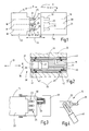
- Weitere Einzelheiten vorteilhafter Ausführungsformen der Erfindung sind Gegenstand von Ansprüchen, der Zeichnung oder der Beschreiben. Es zeigen:
-
Fig. 1 einen Fluidsteckverbinder mit zwei Fluidsteckverbinderteilen, in schematischer Gesamtdarstellung; -
Fig. 2 ein als Buchsenteils ausgebildeten Steckverbinderteil, in schematisierter ausschnittsweiser Vertikalschnittdarstellung; -
Fig. 3 einen als Stecker ausgebildeten Fluidsteckverbinderteil mit Abdeckkappe, die unverlierbar mit dem Stecker verbunden ist, in teilweise geschnittener Draufsicht; -
Fig. 4 den Stecker nachFig. 3 , in Seitenansicht; -
Fig. 5 und 6 Ausführungsformen des als Stecker ausgebildeten Fluidverbinderteils in jeweils ausschnittsweiser, teilweise geschnittener Draufsicht. - In
Fig. 1 ist ein Fluidsteckverbinder 10 veranschaulicht, zu dem zwei Steckverbinderteile 11, 12 gehören, die in einer Steckrichtung 13 zusammenführbar und auseinanderziehbar sind. Das Steckverbinderteil 11 ist als Stecker 14 ausgebildet. Das Steckverbinderteil 12 ist als Fluidsteckdose 15 ausgebildet. - Beispielsweise gehört der Fluidstecker 14 zu einem medizinischen Instrument, beispielsweise einem kryotechnischen Instrument, das im vorliegenden Fall über insgesamt drei Fluidkanäle 16, 17, 18 verfügt, die zur Zu-und Abführung von flüssigen oder gasförmigen Fluiden dienen. Die Fluidkanäle 16 bis 18 setzen sich über rohr-oder schlauchartige Leitungen zu dem distalen Ende des Instruments fort, was in
Fig. 1 nicht weiter dargestellt ist. - Die Fluidkanäle 16 bis 18 kommunizieren im Betriebszustand mit Fluidkanälen 19, 20, 21, die in einem nicht weiter veranschaulichten medizinischen Gerät mit Quellen oder Senken für die Fluide verbunden sind und zu der Fluidsteckdose 15 führen.
- Der Fluidstecker 14 weist ein Steckergehäuse 22 auf, von dem sich zwei oder mehrere, beispielsweise drei Steckstifte 23, 24, 25 in Steckrichtung 13 weg erstrecken. Die Steckstifte 23 bis 25 können, wie es bevorzugt wird, untereinander gleich ausgebildet sein. Sie können jedoch auch unterschiedliche Dimensionen, beispielsweise unterschiedliche Längen und/oder unterschiedliche Querschnitte oder Durchmesser haben, um ein Zusammenfügen des Fluidsteckers 14 mit der Fluidsteckdose 15 nur in einer ausgewählten einzigen Position zu ermöglichen. Die Steckstifte 23 bis 25 können auf einer geraden Linie in gleichen Abständen zueinander oder, um Verwechslungen zu vermeiden, in ungleichen Abständen oder auch auf einer nicht geraden Linie, z.B. im Dreieck oder auf einem Kreisbogen, angeordnet sein. Die Querschnitte der Steckstifte 23 bis 25 sind vorzugsweise Kreisquerschnitte. Es können auch abweichende Querschnittsformen Anwendung finden.
- Unabhängig von Größe und Dimensionierung weist jeder Steckstift 23 bis 25 einen Grundkörper auf, der vorzugsweise im Wesentlichen kreiszylindrisch ist. An seiner Stirn kann eine Einführhilfe 26 vorgesehen sein, beispielsweise in Form einer konischen Fläche 27 (siehe auch
Fig. 5 ). Weiter weist jeder Steckstift 23 bis 25 an seiner vorzugsweise zylindrischen Umfangsfläche 28 zwei Dichtungselemente 29, 30 vorzugsweise in Gestalt von Dichtringen, z.B. O-Ringen auf, zwischen denen eine Fluidöffnungen 31 ausgebildet ist, die mit dem zugeordneten Fluidkanal 16 kommuniziert. Dies gilt entsprechend für alle anderen Steckstifte 23, 24 und die Fluidkanäle 17, 18 in gleicher Weise. - Den Steckstiften 23 bis 25 sind Steckbuchsen 32 bis 34 zugeordnet, die in
Fig. 1 gestrichelt veranschaulicht sind. Die Steckstifte 23 bis 25 und die Steckbuchsen 32 bis 34 werden hier allgemein als "Steckelemente" bezeichnet. -
Fig. 2 veranschaulicht die Steckbuchse 32 exemplarisch und stellvertretend für die anderen beiden Steckbuchsen 33, 34. Mindestens eine, besser zwei, vorzugsweise aber alle Steckbuchsen 32 bis 34 sind in einem Steckverbinderkörper einem Gehäuse 35 der Fluidsteckdose 15 in einer Querrichtung 36 beweglich gelagert. Es kann auch von einer "schwimmenden" Lagerung gesprochen werden. Dazu weist die Steckbuchse 32 eine begrenzte Beweglichkeit in einer ersten Querrichtung 36 auf, die quer zu der Steckrichtung 13 gerichtet ist und die zu der benachbarten Steckbuchse 33 hin und/oder von dieser weggerichtet ist. Zusätzlich oder alternativ können mindestens eine, mehrere oder alle der Steckbuchsen 32 bis 34 in einer anderen Querrichtung, z.B. in einer beliebigen anderen Radialrichtung beweglich gelagert sein. Im vorliegenden Ausführungsbeispiel sind die Steckbuchsen 32 bis 34 in allen Radialrichtungen gleichmäßig beweglich gelagert. - Die Steckbuchse 32 weist eine Buchsenöffnung 37 auf, die im Wesentlichen durch eine Sackbohrung gebildet ist. Der Querschnitt jeder Buchsenöffnung 37 ist auf den Querschnitt des jeweils zugeordneten Steckstifts 23 - 25 passend abgestimmt. An ihrem offenen Ende kann die Buchsenöffnung 37 mit einer Einführhilfe 38 in Gestalt einer konischen Fläche 39 versehen sein. Ansonsten ist die Buchsenöffnung 37 vorzugsweise im Wesentlichen zylindrisch. An einer Stelle, die bei eingestecktem Steckstift 23 auf gleicher Höhe mit der Fluidöffnung 31 liegt, können eine oder mehrere Radialbohrungen 40 vorgesehen sein.
- An dem vorzugsweise zylindrischen Außenumfang der Steckbuchse 32 sind zwei axial voneinander beabstandete Dichtungselemente 41, 42, vorzugsweise Dichtungsringe, z.B. O-Ringe angeordnet, die z.B. in axial voneinander beabstandeten Ringnuten der Steckbuchse 32 sitzen. Zwischen den Dichtungselementen 41, 42 zweigt der Fluidkanal 19 ab, der an der Umfangsfläche der Steckbuchse 32 mündet.
- Die Steckbuchse 32 ist von einer Gasführungshülse 43 aufgenommen, die z.B. als kurzes gerades Rohrstück ausgebildet sein kann. Mit ihrer Innenumfangsfläche liegt sie an den Dichtungselementen 41, 42 der Steckbuchse 32, beispielsweise den O-Ringen, an. Sie begrenzt mit der Steckbuchse 32 einen Gasführungsraum 44, der mit dem Fluidkanal 19 und der Radialbohrung 40 kommuniziert. Ein weiterer Kanal 45 mündet bodenseitig in der Buchsenöffnung 37 und verbindet diese mit dem zwischen der Steckbuchse 32 und der Gasführungshülse 43 ausgebildeten Ringspalt jedoch außerhalb des Gasführungsraums 44. Dieser Kanal 45 dient der Abführung verdrängter Fluide, beispielsweise Luft, beim Einstecken des Steckstifts 23 in die Buchsenöffnung 37.
- Die aus der Steckbuchse 32 und der Gasführungshülse 43 gebildete Einheit ist in dem Gehäuse 35 in einer entsprechenden Aufnahme, zumindest in der einen Querrichtung 36, vorzugsweise aber insgesamt radial z.B. mit Spiel beweglich angeordnet. Zur Vermeidung einer undefinierten Lage und somit zur nachgiebigen Zentrierung der Steckbuchse 32 kann sich die Gasführungshülse 43 auch über mindestens ein oder auch mehrere Federelemente 46 an dem Gehäuse 35 abstützen. Die Federelemente 46 können Metallfedern, beispielsweise in Gestalt von gewellten, ringförmig geschlossenen oder geschlitzten (C-förmigen) Blechringen oder auch Kunststoffelemente, beispielsweise in Gestalt von Ringen, Schnüren oder dergleichen sein. Es kann geschäumtes oder solides Material zum Einsatz kommen. Im vorliegenden Ausführungsbeispiel sind als Federelemente 46 zwei O-Ringe 47, 48 vorgesehen. Es können jedoch auch Federelemente 46, insbesondere O-Ringe, in abweichender Zahl Verwendung finden. Die Federelemente 46 sind in ihrer Federwirkung nachgiebiger ausgebildet als die z.B. durch die O-Ringe gebildeten Dichtungselemente 41, 42. Auf diese Weise bewirkt eine seitliche Verlagerung der Steckbuchse 32 vorzugsweise vorwiegend eine Verformung des mindestens einen Federelements 46, wobei die Gasführungshülse 43 und die Steckbuchse 32 vorzugsweise zueinander im Wesentlichen zentriert bleiben. Auf diese Weise bleibt auch der Gasführungsraum 44 vorzugsweise im Wesentlichen unverformt, d.h. die Spaltweite dieses ringspaltförmigen Raums wird nicht nachteilig geändert.
- Der insoweit beschriebene Fluidsteckverbinder 10 arbeitet wie folgt:
- Zur Beschreibung der Funktion wird davon ausgegangen, dass die Steckstifte 23 bis 25 zwar im Wesentlichen, jedoch nicht exakt mit ihren Steckbuchsen 32 bis 34 fluchten. Wird der Fluidstecker 14 nun in die Fluidsteckdose 15 eingeführt, zentrieren sich die radial beweglichen Steckbuchsen 32, 33, 34, indem die konischen Flächen 27 der Steckstifte 23 bis 25 mit den entsprechenden konischen Flächen 39 der Steckbuchsen 32 bis 34 zusammen wirken und dadurch die jeweilige Steckbuchse 32 bis 34 radial bewegen. Dabei werden die Federelemente 46 entsprechend deformiert. Diese sind ausreichend nachgiebig und geben mit geringer Kraft nach. Die Steckstifte 23 bis 25 können so mit geringer Kraft in die Steckbuchsen 32 bis 34 eingeschoben werden. Die Dichtungen 29, 30 zentrieren dabei den Steckstift 23 in der Steckbuchse 32. Die Dichtungen 29, 30 werden dabei entlang ihres Umfangs im Wesentlichen gleichmäßig verformt. Entsprechendes gilt für die übrigen Paarungen. Die Dichtungen 29, 30 sind erheblich weniger nachgiebig als die Federelemente 46. Wie schon die Dichtungen 41, 42, sind auch die Dichtungen 29, 30 entlang ihres Umfangs im Wesentlichen gleichmäßig verformt. Es ist deshalb eine entlang des gesamten Umfangs gleichmäßig gute und prozesssichere Abdichtung zwischen dem Steckstift 23 und der inneren Wandung der Buchsenöffnung 37 gegeben. Auch ist und bleibt der Gasführungsraum 44 prozesssicher gut abgedichtet.
- In eingestecktem Zustand fluchtet vorzugsweise die Fluidöffnung 31 mit der Radialbohrung 40. Somit sind die Fluidkanäle 16, 19 miteinander in nach außen abgedichteter Kommunikation. Es können auch unter hohem Druck flüssige oder gasförmige Fluide ungestört zwischen den Fluidkanälen 16, 19 ausgetauscht werden.
- Wie die
Figuren 3 und 4 veranschaulichen, kann der Fluidstecker 14 z.B. zu Aufbewahrungszwecken oder zu Reinigungszwecken mit einer Verschlusskappe 49 versehen sein, die an dem Steckergehäuse 22 z.B. verliersicher gehalten sein kann. Eine solche Verschlusskappe 49 kann als Steckbuchsen dienende Blindbuchsen 50 enthalten, wie inFig. 3 lediglich anhand des dem Steckstift 23 zugeordneten Steckplatzes veranschaulicht ist. Die Blindbuchse 50 kann unmittelbar durch die Federmittel 46 an dem Körper der Verschlusskappe 49 abgestützt sein. Wiederum ist die seitliche Beweglichkeit der Blindbuchsen 50 dazu geeignet, etwaige Abstandstoleranzen oder sonstige Anordnungstoleranzen der Steckstifte 23 bis 25 auszugleichen und so ein leichtes Aufstecken der Abdeckkappe 49 zu ermöglichen, ohne dabei die Dichtungen 29, 30 zu beschädigen oder zu überanspruchen. - Bei der vorigen Beschreibung ist davon ausgegangen worden, dass zumindest zwei der drei Steckbuchsen 32 bis 34 radial beweglich angeordnet sind, wobei die radiale Beweglichkeit durch eine entsprechend zentrierende Federkraft des mindestens einen Federelements 46 nicht eingeschränkt wird. Die von dem(den) Federelement(en) 46 verursachte Federkraft ist geringer als die von den Dichtungen 29, 30 oder den Dichtungen 41, 42 erzeugte Federkraft. Dabei können die Steckstifte 23 bis 25 an dem Steckergehäuse 22 starr angeordnet sein. Es ist jedoch alternativ oder ergänzend möglich, wenigstens einen, mehrere oder alle der Steckerstifte 23 bis 25 radial beweglich zu lagern. Ausführungsbeispiele dafür sind in den
Figuren 5 und 6 angegeben. - Das Steckergehäuse 22 kann eine Kammer 51 zur Aufnahme eines Endes 53 des Steckstifts 23 aufweisen. Das Steckergehäuse 22 kann eine nicht dargestellte Trennfuge aufweisen, die durch die Kammer 51 verläuft und die Montage des Steckstifts 23 ermöglicht. Dieser kann in der Kammer 51 mit einer Dichtung 53 abgedichtet gehalten sein. Die Dichtung 53 dient hier zugleich als Federmittel. Sie kann so weich ausgebildet sein, dass sie einer Radialbewegung des Steckstifts 23 eine Kraft entgegensetzt, die wesentlich geringer ist als eine entsprechende, bei gleicher Deformation von den Dichtungen 29, 30 verursachte Kraft. Die Kammer 51 kommuniziert mit dem Fluidkanal 16 der, wie in
Fig. 5 gestrichelt veranschaulicht, sich axial durch den Steckstift 23 bis zu der Fluidöffnung 31 hin fortsetzt. - Eine andere Ausführungsform nach
Fig. 6 nutzt den Fluidstecker 23 als direkten Anschluss für einen Fluidschlauch 54, der durch geeignete, nicht weiter veranschaulichte Fluidverbindungsmittel unmittelbar mit dem proximalen Ende des Steckstifts 23 verbunden ist. Der Steckstift 23 erstreckt sich mit radialem Spiel durch eine Öffnung 55 des Steckergehäuses 22. Zur axialen Abstützung kann der Steckstift 23 mit einem Bund 56, der mit Spiel in einer entsprechenden Ringnut der Öffnung 55 sitzt, oder anderem geeigneten Axialbefestigungsmittel versehen sein. An dem Steckstift 23 können Federmittel 57 angebracht sein, beispielsweise in Gestalt eines oder zweier Elastomerringe 58, 59. Diese Elastomerringe 58, 59 können beispielsweise durch O-Ringe, vorzugsweise weiche O-Ringe gebildet sein. Alternativ können andere Federmittel zum Einsatz kommen. - Wie schon bei den Steckbuchsen 32 bis 34 kann auf die Federmittel 46 bzw. 57 auch verzichtet werden. Außerdem können sie durch Strukturen des Steckergehäuses 22 bzw. des Gehäuses 35 ersetzt sein, wie beispielsweise durch einzelne oder mehrere Kunststoffzungen, eine zunächst formlose und dann aushärtende Elastomermasse oder ähnliches.
- Ein Fluidsteckverbinder weist Steckelemente, beispielsweise in Gestalt von Steckstiften 23 bis 25 oder Steckbuchsen 32 bis 34 auf, die quer zu einer Steckrichtung 13 wenigsten geringfügig beweglich gelagert sind. Federmittel 46, 57 können zur Vorgabe einer Ruheposition der entsprechenden Steckelemente dienen, um sie beweglich und spielfrei anzuordnen. Dadurch wird ein Klappern verhindert und/oder das Entstehen einer sichtbaren, unregelmäßig, nicht konzentrischen Anordnung einer Steckbuchse 32 zu einer Bohrung in dem Gehäuse 35. Diese nicht konzentrische Anordnung könnte als optischer, bzw. qualitativer Mangel empfunden werden..
-
- 10
- Fluidsteckverbinder
- 11, 12
- Steckverbinderteil
- 13
- Steckrichtung
- 14
- Fluidstecker, umfasst einen oder mehrere Steckstifte 23 - 25
- 15
- Fluidsteckdose, umfasst eine oder mehrere Steckbuchsen 32 - 34
- 16 - 18
- Fluidkanal
- 19 - 21
- Fluidkanal
- 22
- Steckergehäuse
- 23 - 25
- Steckstift
- 26
- Einführhilfe
- 27
- Fläche
- 28
- Umfangsfläche
- 29, 30
- Dichtungen
- 31
- Fluidöffnung
- 32 - 34
- Steckbuchse
- 35
- Steckverbinderkörper, Gehäuse
- 36
- Querrichtung
- 37
- Buchsenöffnung
- 38
- Einführhilfe
- 39
- Fläche
- 40
- Radialbohrung
- 41, 42
- Dichtungselement, O-Ring
- 43
- Gasführungshülse
- 44
- Gasführungsraum
- 45
- Kanal
- 46
- Federelement
- 47, 48
- O-Ring
- 49
- Verschlusskappe
- 50
- Blindbuchse
- 51
- Kammer
- 52
- Ende
- 53
- Dichtung
- 54
- Schlauch
- 55
- Öffnung
- 56
- Bund
- 57
- Federmittel
- 58, 59
- Elastomerring
Claims (15)
- Fluidsteckverbinderteil (11, 12) insbesondere für medizinische Geräte oder Instrumente;
das mindestens zwei Steckelemente (23 - 25; 32 - 34) aufweist, die eine gemeinsame Steckrichtung (13) festlegen,
wobei wenigstens eines der Steckelemente (23 - 25; 32 - 34) in mindestens einer Querrichtung (36) beweglich gelagert ist, die zu der Steckrichtung (13) quer orientiert ist. - Fluidsteckverbinderteil nach Anspruch 1, dadurch gekennzeichnet, dass die Steckelemente (23 - 25; 32 - 34) Steckbuchsen (32 - 34) oder Steckstifte (23 - 25) sind.
- Fluidsteckverbinderteil nach einem der vorstehenden Ansprüche, dadurch gekennzeichnet, dass alle Steckelemente (23 - 25; 32 - 34) in der mindestens einen Querrichtung (36) beweglich gelagert sind.
- Fluidsteckverbinderteil nach einem der vorstehenden Ansprüche, dadurch gekennzeichnet, dass die Steckelemente (23 - 25; 32 - 34) in der Querrichtung (36) aufeinander zu und voneinander weg beweglich gelagert sind.
- Fluidsteckverbinderteil nach einem der vorstehenden Ansprüche, dadurch gekennzeichnet, dass mindestens eines der Steckelemente (23 - 25; 32 - 34) in allen radial zu der Steckrichtung (13) orientierten Richtungen beweglich ist.
- Fluidsteckverbinderteil nach einem der vorstehenden Ansprüche, dadurch gekennzeichnet, dass die Steckelemente (23-25; 32 - 34) in einer Reihe angeordnet sind.
- Fluidsteckverbinderteil nach einem der vorstehenden Ansprüche, dadurch gekennzeichnet, dass wenigstens eines der beweglich gelagerten Steckelemente (23 - 25; 32 - 34) in Querrichtung (36) federnd gelagert sind.
- Fluidsteckverbinderteil nach einem der vorstehenden Ansprüche, dadurch gekennzeichnet, dass das beweglich gelagerte Steckelement (32 - 34) von einer beweglich gelagerten Gasführungshülse (43) umgeben ist.
- Fluidsteckverbinderteil nach Anspruch 8, dadurch gekennzeichnet, dass die Gasführungshülse (43) durch mindestens ein Federelement (46) an einem Steckverbinderkörper (35) abgestützt ist.
- Fluidsteckverbinderteil nach einem der vorstehenden Ansprüche, dadurch gekennzeichnet, dass die Gasführungshülse (43) durch ein oder mehrere voneinander beabstandete Federelemente (46) an einem Steckverbinderkörper (35) abgestützt sind.
- Fluidsteckverbinderteil nach Anspruch 10, dadurch gekennzeichnet, dass die Federelemente (46) ringförmige Elastomerkörper sind.
- Fluidsteckverbinderteil nach einem der vorstehenden Ansprüche, dadurch gekennzeichnet, dass das Steckelement (32 - 34) mit zwei voneinander beabstandeten Dichtungselementen (41, 42) in der Gasführungshülse (43) einen Gasführungsraum (44) abgrenzt.
- Fluidsteckverbinderteil nach Anspruch 12, dadurch gekennzeichnet, dass das Steckelement (32 - 34) mindestens eine Radialbohrung (40) aufweist, die den Gasführungsraum (44) mit einer Buchsenöffnung (37) verbindet.
- Fluidsteckverbinderteil nach einem der vorstehenden Ansprüche, dadurch gekennzeichnet, dass das Steckelement (23 - 25; 32 - 34) an seiner Stirnseite eine Einführhilfe (26, 38) aufweist.
- Fluidsteckverbinderteil nach einem der vorstehenden Ansprüche, dadurch gekennzeichnet, dass die Einführhilfe (26, 38) durch eine Konusfläche (27, 39) gebildet ist.
Priority Applications (8)
| Application Number | Priority Date | Filing Date | Title |
|---|---|---|---|
| EP12156560.0A EP2630983B1 (de) | 2012-02-22 | 2012-02-22 | Fluidkupplung mit mehreren radial beweglichen Steckelementen |
| PL12156560T PL2630983T3 (pl) | 2012-02-22 | 2012-02-22 | Złącze płynowe z wieloma promieniowo ruchomymi elementami wtykowymi |
| RU2013107802/14A RU2544296C2 (ru) | 2012-02-22 | 2013-02-21 | Компонент соединителя текучей среды, содержащий несколько встраиваемых элементов |
| KR1020130018849A KR101506073B1 (ko) | 2012-02-22 | 2013-02-21 | 여러 개의 플러깅가능한 요소를 포함하는 유체 커넥터 구성요소 |
| BR102013004200-5A BR102013004200B1 (pt) | 2012-02-22 | 2013-02-22 | Componente de conector de fluído |
| US13/774,343 US8740257B2 (en) | 2012-02-22 | 2013-02-22 | Fluid connector component comprising several pluggable elements |
| CN201310163102.0A CN103349813B (zh) | 2012-02-22 | 2013-02-22 | 具有若干可插接元件的流体连接器组件 |
| JP2013033071A JP5802227B2 (ja) | 2012-02-22 | 2013-02-22 | いくつかのプラグ接続式要素を備える流体コネクタコンポーネント |
Applications Claiming Priority (1)
| Application Number | Priority Date | Filing Date | Title |
|---|---|---|---|
| EP12156560.0A EP2630983B1 (de) | 2012-02-22 | 2012-02-22 | Fluidkupplung mit mehreren radial beweglichen Steckelementen |
Publications (2)
| Publication Number | Publication Date |
|---|---|
| EP2630983A1 true EP2630983A1 (de) | 2013-08-28 |
| EP2630983B1 EP2630983B1 (de) | 2016-10-26 |
Family
ID=45656456
Family Applications (1)
| Application Number | Title | Priority Date | Filing Date |
|---|---|---|---|
| EP12156560.0A Active EP2630983B1 (de) | 2012-02-22 | 2012-02-22 | Fluidkupplung mit mehreren radial beweglichen Steckelementen |
Country Status (8)
| Country | Link |
|---|---|
| US (1) | US8740257B2 (de) |
| EP (1) | EP2630983B1 (de) |
| JP (1) | JP5802227B2 (de) |
| KR (1) | KR101506073B1 (de) |
| CN (1) | CN103349813B (de) |
| BR (1) | BR102013004200B1 (de) |
| PL (1) | PL2630983T3 (de) |
| RU (1) | RU2544296C2 (de) |
Families Citing this family (10)
| Publication number | Priority date | Publication date | Assignee | Title |
|---|---|---|---|---|
| EP2902582B2 (de) * | 2014-01-29 | 2022-12-28 | BAUER Maschinen GmbH | Mastanordnung und Verfahren zum Verbinden einer Werkzeugeinheit mit einem Mastschlitten einer Mastanordnung |
| GB2524771B (en) | 2014-04-02 | 2019-08-21 | Gyrus Medical Ltd | Electrosurgical system |
| US10053046B2 (en) * | 2015-09-04 | 2018-08-21 | Ford Global Technologies, Llc | Side pillar air curtain guide |
| US9968021B2 (en) * | 2016-01-19 | 2018-05-15 | Deere & Company | Work vehicle multi-coupler with breakaway feature |
| JP7004386B2 (ja) * | 2016-09-29 | 2022-02-04 | ニッタ株式会社 | 管継手及び継手連結装置 |
| US10828065B2 (en) * | 2017-08-28 | 2020-11-10 | Covidien Lp | Surgical access system |
| US10806066B2 (en) | 2018-05-18 | 2020-10-20 | Deere & Company | Implement multi-coupler with breakaway feature |
| CN115038396A (zh) * | 2019-10-29 | 2022-09-09 | 帕西拉冷冻技术股份有限公司 | 带有快速连接的针式探头的低温装置 |
| CN116697167A (zh) * | 2022-02-25 | 2023-09-05 | 中国航发商用航空发动机有限责任公司 | 多通道流体连接器 |
| EP4527328A1 (de) * | 2023-09-21 | 2025-03-26 | Erbe Elektromedizin GmbH | Ablationsinstrument |
Citations (9)
| Publication number | Priority date | Publication date | Assignee | Title |
|---|---|---|---|---|
| US2086424A (en) * | 1934-05-05 | 1937-07-06 | Charles H Koehler | Electrical contact device |
| US3214195A (en) * | 1962-05-25 | 1965-10-26 | Crawford Fitting Co | Coupling device for interconnecting multiple fluid lines |
| US3337181A (en) * | 1964-12-10 | 1967-08-22 | Cajon Co | Adjustable manifold fitting |
| US3508580A (en) * | 1967-09-12 | 1970-04-28 | Srm Co | Fluid-tight coupling for laterally misaligned conduits |
| US3937496A (en) * | 1974-12-09 | 1976-02-10 | Greer Hydraulics, Inc. | Flexible coupling |
| GB2419647A (en) * | 2004-10-29 | 2006-05-03 | Visteon Global Tech Inc | Quick connect coupling |
| WO2007118334A1 (en) * | 2006-04-19 | 2007-10-25 | Taimi R & D Inc. | Multifunctionally swivelling coupling assembly for fluid lines |
| WO2008142672A1 (en) * | 2007-05-21 | 2008-11-27 | Stryker Gi Ltd. | Disposable connector for use with endoscopic apparatus |
| US20100181764A1 (en) * | 2007-06-07 | 2010-07-22 | Imoto Yuki | Pipe joint coupling apparatus |
Family Cites Families (21)
| Publication number | Priority date | Publication date | Assignee | Title |
|---|---|---|---|---|
| US1973610A (en) * | 1932-09-19 | 1934-09-11 | Highway Trailer Co | Automatic coupling and shut-off mechanism for vehicle hose lines |
| DE1440871B2 (de) * | 1961-07-31 | 1973-10-31 | International Standard Electric Corp., New York, N.Y. (V.St.A.) | Elektrischer Subminiatur Steckver binder |
| US3469863A (en) * | 1967-04-05 | 1969-09-30 | Trico Products Corp | Fluid coupling assembly |
| JPS5229620U (de) * | 1975-08-22 | 1977-03-02 | ||
| NO140919C (no) * | 1978-04-17 | 1979-12-12 | Helge Dybvig | Anordning ved drivstoffsystem, saerlig for baater |
| IT211623Z2 (it) * | 1986-11-03 | 1989-04-07 | Murray Europ | Raccordo per fluidi. |
| JP2678760B2 (ja) * | 1988-02-29 | 1997-11-17 | 旭エンジニアリング株式会社 | 自動配管接続用芯ずれ矯正装置 |
| US5197895A (en) * | 1991-05-10 | 1993-03-30 | Bicore Monitoring Systems | Disposable electro-fluidic connector with data storage |
| GB9123412D0 (en) * | 1991-11-05 | 1991-12-18 | Clarke Brian K R | Improvements in or relating to coupling assemblies |
| DE4138064C1 (de) * | 1991-11-19 | 1993-05-06 | Kreuzer Gmbh + Co Ohg, 8039 Puchheim, De | |
| DE10026769C2 (de) * | 2000-06-04 | 2003-03-06 | Frank Prochiner | Verbindungskonstruktion zum Verbinden von Bauteilen |
| GB2380241B (en) * | 2001-07-12 | 2003-08-20 | Huntleigh Technology Plc | Connector |
| US6860516B2 (en) * | 2001-12-07 | 2005-03-01 | Pentax Corporation | Channel tube coupling structure for anti-pollution type endoscope |
| DE20319959U1 (de) * | 2003-12-23 | 2005-05-04 | Voss Automotive Gmbh | Steckverbinder für Medienleitungen |
| US7021668B2 (en) * | 2004-02-06 | 2006-04-04 | Westendorf Manufacturing Co., Inc. | Hydraulic line attachment device and method |
| DE102004037459A1 (de) * | 2004-08-02 | 2006-02-23 | Liebherr-Hydraulikbagger Gmbh | Hydraulikschnellkupplung |
| DE102004052475A1 (de) | 2004-10-28 | 2006-05-04 | Eaton Fluid Power Gmbh | Zugfeste Steckkupplung |
| CN101330880B (zh) * | 2005-12-16 | 2011-04-20 | 爱尔伯电子医疗设备公司 | 具有由插座和冷冻探针的插头形成的探针耦合的冷冻治疗设备 |
| GB0604952D0 (en) * | 2006-03-13 | 2006-04-19 | Renishaw Plc | A fluid connector for fluid delivery apparatus |
| CN2915149Y (zh) * | 2006-04-20 | 2007-06-27 | 深圳迈瑞生物医疗电子股份有限公司 | 一种流体管道连接器 |
| US7780201B2 (en) * | 2006-10-13 | 2010-08-24 | Medela Holding Ag | Tube connector with three part construction and latching component |
-
2012
- 2012-02-22 PL PL12156560T patent/PL2630983T3/pl unknown
- 2012-02-22 EP EP12156560.0A patent/EP2630983B1/de active Active
-
2013
- 2013-02-21 KR KR1020130018849A patent/KR101506073B1/ko active Active
- 2013-02-21 RU RU2013107802/14A patent/RU2544296C2/ru active
- 2013-02-22 JP JP2013033071A patent/JP5802227B2/ja active Active
- 2013-02-22 BR BR102013004200-5A patent/BR102013004200B1/pt active IP Right Grant
- 2013-02-22 CN CN201310163102.0A patent/CN103349813B/zh active Active
- 2013-02-22 US US13/774,343 patent/US8740257B2/en active Active
Patent Citations (9)
| Publication number | Priority date | Publication date | Assignee | Title |
|---|---|---|---|---|
| US2086424A (en) * | 1934-05-05 | 1937-07-06 | Charles H Koehler | Electrical contact device |
| US3214195A (en) * | 1962-05-25 | 1965-10-26 | Crawford Fitting Co | Coupling device for interconnecting multiple fluid lines |
| US3337181A (en) * | 1964-12-10 | 1967-08-22 | Cajon Co | Adjustable manifold fitting |
| US3508580A (en) * | 1967-09-12 | 1970-04-28 | Srm Co | Fluid-tight coupling for laterally misaligned conduits |
| US3937496A (en) * | 1974-12-09 | 1976-02-10 | Greer Hydraulics, Inc. | Flexible coupling |
| GB2419647A (en) * | 2004-10-29 | 2006-05-03 | Visteon Global Tech Inc | Quick connect coupling |
| WO2007118334A1 (en) * | 2006-04-19 | 2007-10-25 | Taimi R & D Inc. | Multifunctionally swivelling coupling assembly for fluid lines |
| WO2008142672A1 (en) * | 2007-05-21 | 2008-11-27 | Stryker Gi Ltd. | Disposable connector for use with endoscopic apparatus |
| US20100181764A1 (en) * | 2007-06-07 | 2010-07-22 | Imoto Yuki | Pipe joint coupling apparatus |
Also Published As
| Publication number | Publication date |
|---|---|
| JP2013169469A (ja) | 2013-09-02 |
| KR20130096672A (ko) | 2013-08-30 |
| CN103349813B (zh) | 2015-04-01 |
| PL2630983T3 (pl) | 2017-04-28 |
| BR102013004200B1 (pt) | 2021-03-23 |
| RU2013107802A (ru) | 2014-08-27 |
| US8740257B2 (en) | 2014-06-03 |
| CN103349813A (zh) | 2013-10-16 |
| EP2630983B1 (de) | 2016-10-26 |
| BR102013004200A2 (pt) | 2017-11-28 |
| KR101506073B1 (ko) | 2015-03-25 |
| JP5802227B2 (ja) | 2015-10-28 |
| US20130214527A1 (en) | 2013-08-22 |
| RU2544296C2 (ru) | 2015-03-20 |
Similar Documents
| Publication | Publication Date | Title |
|---|---|---|
| EP2630983B1 (de) | Fluidkupplung mit mehreren radial beweglichen Steckelementen | |
| DE3100037C2 (de) | ||
| DE102011118099A1 (de) | Vorrichtung zum Verbinden zweier Leitungsabschnitte | |
| DE102013200533B4 (de) | Ventilpatrone | |
| EP2446181B1 (de) | Vorrichtung zum verbinden von zwei leitungsabschnitten, insbesondere eine mehrfachkupplung mit einem integrierten absperrventil | |
| EP3081303B1 (de) | Rührwerkskugelmühle | |
| DE102023117369B4 (de) | Kugelventil einer Kältemittelventileinrichtung für eine Klimaanlage | |
| WO2021089754A1 (de) | Gegendorn-kupplungselement, dorn-kupplungselement sowie kupplungssystem für ein geschlossenes fluidtransfersystem | |
| DE112015001056T5 (de) | Vacuumpumpe | |
| EP3982028A1 (de) | Verteilerbaugruppe, insbesondere für eine separationseinheit einer modularen prozess-vorrichtungsanordnung | |
| DE102010046383A1 (de) | Verbindungsanordnung zum Verbinden von hydraulischen Bauteilen | |
| EP3679282B1 (de) | Ventilanordnung | |
| EP3887703A1 (de) | Fluidverbindung | |
| DE112021002981T5 (de) | Schnellverbinder für fluidleitungen mit positivbestätigungsfunktion | |
| EP3699462A1 (de) | Ventilsitz-käfiganordnung | |
| EP1321698A2 (de) | Einrichtung zum Zusammenschalten mehrerer hydraulischer oder pneumatischer Komponenten, insbesondere mehrerer Elektromagnetventile | |
| DE102019128040B4 (de) | Steckverbinder | |
| DE102005052486A1 (de) | Filtereinrichtung | |
| DE102017120695A1 (de) | Ventilanordnung | |
| DE102009033365B4 (de) | Rückschlagventil | |
| DE102021102585A1 (de) | Steckverbindungen zum lösbaren Verbinden von Leitungen und System umfassend eine solche Steckverbindung | |
| EP4560173B1 (de) | Steckkupplung | |
| EP4671582A1 (de) | Ventilkörper, ventilblock und verfahren | |
| DE2308191A1 (de) | Druckmittelverteiler | |
| DE2805980A1 (de) | Steuer- und durchblaseventil fuer dampf und heizoel |
Legal Events
| Date | Code | Title | Description |
|---|---|---|---|
| PUAI | Public reference made under article 153(3) epc to a published international application that has entered the european phase |
Free format text: ORIGINAL CODE: 0009012 |
|
| AK | Designated contracting states |
Kind code of ref document: A1 Designated state(s): AL AT BE BG CH CY CZ DE DK EE ES FI FR GB GR HR HU IE IS IT LI LT LU LV MC MK MT NL NO PL PT RO RS SE SI SK SM TR |
|
| AX | Request for extension of the european patent |
Extension state: BA ME |
|
| 17P | Request for examination filed |
Effective date: 20130918 |
|
| RBV | Designated contracting states (corrected) |
Designated state(s): AL AT BE BG CH CY CZ DE DK EE ES FI FR GB GR HR HU IE IS IT LI LT LU LV MC MK MT NL NO PL PT RO RS SE SI SK SM TR |
|
| 17Q | First examination report despatched |
Effective date: 20140620 |
|
| RIC1 | Information provided on ipc code assigned before grant |
Ipc: A61M 39/10 20060101AFI20160204BHEP Ipc: A61B 18/02 20060101ALI20160204BHEP Ipc: F16L 37/56 20060101ALI20160204BHEP Ipc: A61M 39/12 20060101ALN20160204BHEP Ipc: A61M 39/20 20060101ALN20160204BHEP Ipc: F16L 39/04 20060101ALI20160204BHEP |
|
| GRAP | Despatch of communication of intention to grant a patent |
Free format text: ORIGINAL CODE: EPIDOSNIGR1 |
|
| INTG | Intention to grant announced |
Effective date: 20160404 |
|
| GRAS | Grant fee paid |
Free format text: ORIGINAL CODE: EPIDOSNIGR3 |
|
| INTC | Intention to grant announced (deleted) | ||
| GRAR | Information related to intention to grant a patent recorded |
Free format text: ORIGINAL CODE: EPIDOSNIGR71 |
|
| GRAA | (expected) grant |
Free format text: ORIGINAL CODE: 0009210 |
|
| AK | Designated contracting states |
Kind code of ref document: B1 Designated state(s): AL AT BE BG CH CY CZ DE DK EE ES FI FR GB GR HR HU IE IS IT LI LT LU LV MC MK MT NL NO PL PT RO RS SE SI SK SM TR |
|
| INTG | Intention to grant announced |
Effective date: 20160919 |
|
| REG | Reference to a national code |
Ref country code: GB Ref legal event code: FG4D Free format text: NOT ENGLISH |
|
| REG | Reference to a national code |
Ref country code: CH Ref legal event code: EP |
|
| REG | Reference to a national code |
Ref country code: AT Ref legal event code: REF Ref document number: 839585 Country of ref document: AT Kind code of ref document: T Effective date: 20161115 |
|
| REG | Reference to a national code |
Ref country code: IE Ref legal event code: FG4D Free format text: LANGUAGE OF EP DOCUMENT: GERMAN |
|
| REG | Reference to a national code |
Ref country code: DE Ref legal event code: R096 Ref document number: 502012008612 Country of ref document: DE |
|
| RAP2 | Party data changed (patent owner data changed or rights of a patent transferred) |
Owner name: ERBE ELEKTROMEDIZIN GMBH |
|
| RAP2 | Party data changed (patent owner data changed or rights of a patent transferred) |
Owner name: ERBE ELEKTROMEDIZIN GMBH |
|
| REG | Reference to a national code |
Ref country code: LT Ref legal event code: MG4D Ref country code: FR Ref legal event code: PLFP Year of fee payment: 6 |
|
| PG25 | Lapsed in a contracting state [announced via postgrant information from national office to epo] |
Ref country code: LV Free format text: LAPSE BECAUSE OF FAILURE TO SUBMIT A TRANSLATION OF THE DESCRIPTION OR TO PAY THE FEE WITHIN THE PRESCRIBED TIME-LIMIT Effective date: 20161026 |
|
| REG | Reference to a national code |
Ref country code: NL Ref legal event code: MP Effective date: 20161026 |
|
| PG25 | Lapsed in a contracting state [announced via postgrant information from national office to epo] |
Ref country code: SE Free format text: LAPSE BECAUSE OF FAILURE TO SUBMIT A TRANSLATION OF THE DESCRIPTION OR TO PAY THE FEE WITHIN THE PRESCRIBED TIME-LIMIT Effective date: 20161026 Ref country code: GR Free format text: LAPSE BECAUSE OF FAILURE TO SUBMIT A TRANSLATION OF THE DESCRIPTION OR TO PAY THE FEE WITHIN THE PRESCRIBED TIME-LIMIT Effective date: 20170127 Ref country code: LT Free format text: LAPSE BECAUSE OF FAILURE TO SUBMIT A TRANSLATION OF THE DESCRIPTION OR TO PAY THE FEE WITHIN THE PRESCRIBED TIME-LIMIT Effective date: 20161026 Ref country code: NO Free format text: LAPSE BECAUSE OF FAILURE TO SUBMIT A TRANSLATION OF THE DESCRIPTION OR TO PAY THE FEE WITHIN THE PRESCRIBED TIME-LIMIT Effective date: 20170126 |
|
| PG25 | Lapsed in a contracting state [announced via postgrant information from national office to epo] |
Ref country code: HR Free format text: LAPSE BECAUSE OF FAILURE TO SUBMIT A TRANSLATION OF THE DESCRIPTION OR TO PAY THE FEE WITHIN THE PRESCRIBED TIME-LIMIT Effective date: 20161026 Ref country code: NL Free format text: LAPSE BECAUSE OF FAILURE TO SUBMIT A TRANSLATION OF THE DESCRIPTION OR TO PAY THE FEE WITHIN THE PRESCRIBED TIME-LIMIT Effective date: 20161026 Ref country code: FI Free format text: LAPSE BECAUSE OF FAILURE TO SUBMIT A TRANSLATION OF THE DESCRIPTION OR TO PAY THE FEE WITHIN THE PRESCRIBED TIME-LIMIT Effective date: 20161026 Ref country code: BE Free format text: LAPSE BECAUSE OF NON-PAYMENT OF DUE FEES Effective date: 20170228 Ref country code: IS Free format text: LAPSE BECAUSE OF FAILURE TO SUBMIT A TRANSLATION OF THE DESCRIPTION OR TO PAY THE FEE WITHIN THE PRESCRIBED TIME-LIMIT Effective date: 20170226 Ref country code: PT Free format text: LAPSE BECAUSE OF FAILURE TO SUBMIT A TRANSLATION OF THE DESCRIPTION OR TO PAY THE FEE WITHIN THE PRESCRIBED TIME-LIMIT Effective date: 20170227 Ref country code: RS Free format text: LAPSE BECAUSE OF FAILURE TO SUBMIT A TRANSLATION OF THE DESCRIPTION OR TO PAY THE FEE WITHIN THE PRESCRIBED TIME-LIMIT Effective date: 20161026 Ref country code: ES Free format text: LAPSE BECAUSE OF FAILURE TO SUBMIT A TRANSLATION OF THE DESCRIPTION OR TO PAY THE FEE WITHIN THE PRESCRIBED TIME-LIMIT Effective date: 20161026 |
|
| REG | Reference to a national code |
Ref country code: DE Ref legal event code: R097 Ref document number: 502012008612 Country of ref document: DE |
|
| PG25 | Lapsed in a contracting state [announced via postgrant information from national office to epo] |
Ref country code: DK Free format text: LAPSE BECAUSE OF FAILURE TO SUBMIT A TRANSLATION OF THE DESCRIPTION OR TO PAY THE FEE WITHIN THE PRESCRIBED TIME-LIMIT Effective date: 20161026 Ref country code: EE Free format text: LAPSE BECAUSE OF FAILURE TO SUBMIT A TRANSLATION OF THE DESCRIPTION OR TO PAY THE FEE WITHIN THE PRESCRIBED TIME-LIMIT Effective date: 20161026 Ref country code: SK Free format text: LAPSE BECAUSE OF FAILURE TO SUBMIT A TRANSLATION OF THE DESCRIPTION OR TO PAY THE FEE WITHIN THE PRESCRIBED TIME-LIMIT Effective date: 20161026 Ref country code: RO Free format text: LAPSE BECAUSE OF FAILURE TO SUBMIT A TRANSLATION OF THE DESCRIPTION OR TO PAY THE FEE WITHIN THE PRESCRIBED TIME-LIMIT Effective date: 20161026 Ref country code: CZ Free format text: LAPSE BECAUSE OF FAILURE TO SUBMIT A TRANSLATION OF THE DESCRIPTION OR TO PAY THE FEE WITHIN THE PRESCRIBED TIME-LIMIT Effective date: 20161026 |
|
| PG25 | Lapsed in a contracting state [announced via postgrant information from national office to epo] |
Ref country code: BG Free format text: LAPSE BECAUSE OF FAILURE TO SUBMIT A TRANSLATION OF THE DESCRIPTION OR TO PAY THE FEE WITHIN THE PRESCRIBED TIME-LIMIT Effective date: 20170126 Ref country code: SM Free format text: LAPSE BECAUSE OF FAILURE TO SUBMIT A TRANSLATION OF THE DESCRIPTION OR TO PAY THE FEE WITHIN THE PRESCRIBED TIME-LIMIT Effective date: 20161026 |
|
| PLBE | No opposition filed within time limit |
Free format text: ORIGINAL CODE: 0009261 |
|
| STAA | Information on the status of an ep patent application or granted ep patent |
Free format text: STATUS: NO OPPOSITION FILED WITHIN TIME LIMIT |
|
| PG25 | Lapsed in a contracting state [announced via postgrant information from national office to epo] |
Ref country code: MC Free format text: LAPSE BECAUSE OF FAILURE TO SUBMIT A TRANSLATION OF THE DESCRIPTION OR TO PAY THE FEE WITHIN THE PRESCRIBED TIME-LIMIT Effective date: 20161026 |
|
| REG | Reference to a national code |
Ref country code: CH Ref legal event code: PL |
|
| 26N | No opposition filed |
Effective date: 20170727 |
|
| PG25 | Lapsed in a contracting state [announced via postgrant information from national office to epo] |
Ref country code: LI Free format text: LAPSE BECAUSE OF NON-PAYMENT OF DUE FEES Effective date: 20170228 Ref country code: CH Free format text: LAPSE BECAUSE OF NON-PAYMENT OF DUE FEES Effective date: 20170228 |
|
| REG | Reference to a national code |
Ref country code: IE Ref legal event code: MM4A |
|
| PG25 | Lapsed in a contracting state [announced via postgrant information from national office to epo] |
Ref country code: SI Free format text: LAPSE BECAUSE OF FAILURE TO SUBMIT A TRANSLATION OF THE DESCRIPTION OR TO PAY THE FEE WITHIN THE PRESCRIBED TIME-LIMIT Effective date: 20161026 |
|
| PG25 | Lapsed in a contracting state [announced via postgrant information from national office to epo] |
Ref country code: LU Free format text: LAPSE BECAUSE OF NON-PAYMENT OF DUE FEES Effective date: 20170222 |
|
| REG | Reference to a national code |
Ref country code: BE Ref legal event code: MM Effective date: 20170228 |
|
| REG | Reference to a national code |
Ref country code: FR Ref legal event code: PLFP Year of fee payment: 7 |
|
| PG25 | Lapsed in a contracting state [announced via postgrant information from national office to epo] |
Ref country code: IE Free format text: LAPSE BECAUSE OF NON-PAYMENT OF DUE FEES Effective date: 20170222 |
|
| REG | Reference to a national code |
Ref country code: AT Ref legal event code: MM01 Ref document number: 839585 Country of ref document: AT Kind code of ref document: T Effective date: 20170222 |
|
| PG25 | Lapsed in a contracting state [announced via postgrant information from national office to epo] |
Ref country code: AT Free format text: LAPSE BECAUSE OF NON-PAYMENT OF DUE FEES Effective date: 20170222 |
|
| PG25 | Lapsed in a contracting state [announced via postgrant information from national office to epo] |
Ref country code: MT Free format text: LAPSE BECAUSE OF FAILURE TO SUBMIT A TRANSLATION OF THE DESCRIPTION OR TO PAY THE FEE WITHIN THE PRESCRIBED TIME-LIMIT Effective date: 20161026 |
|
| PG25 | Lapsed in a contracting state [announced via postgrant information from national office to epo] |
Ref country code: HU Free format text: LAPSE BECAUSE OF FAILURE TO SUBMIT A TRANSLATION OF THE DESCRIPTION OR TO PAY THE FEE WITHIN THE PRESCRIBED TIME-LIMIT; INVALID AB INITIO Effective date: 20120222 |
|
| PG25 | Lapsed in a contracting state [announced via postgrant information from national office to epo] |
Ref country code: CY Free format text: LAPSE BECAUSE OF NON-PAYMENT OF DUE FEES Effective date: 20161026 |
|
| PG25 | Lapsed in a contracting state [announced via postgrant information from national office to epo] |
Ref country code: MK Free format text: LAPSE BECAUSE OF FAILURE TO SUBMIT A TRANSLATION OF THE DESCRIPTION OR TO PAY THE FEE WITHIN THE PRESCRIBED TIME-LIMIT Effective date: 20161026 |
|
| PG25 | Lapsed in a contracting state [announced via postgrant information from national office to epo] |
Ref country code: TR Free format text: LAPSE BECAUSE OF FAILURE TO SUBMIT A TRANSLATION OF THE DESCRIPTION OR TO PAY THE FEE WITHIN THE PRESCRIBED TIME-LIMIT Effective date: 20161026 |
|
| PG25 | Lapsed in a contracting state [announced via postgrant information from national office to epo] |
Ref country code: AL Free format text: LAPSE BECAUSE OF FAILURE TO SUBMIT A TRANSLATION OF THE DESCRIPTION OR TO PAY THE FEE WITHIN THE PRESCRIBED TIME-LIMIT Effective date: 20161026 |
|
| PGFP | Annual fee paid to national office [announced via postgrant information from national office to epo] |
Ref country code: GB Payment date: 20260223 Year of fee payment: 15 |
|
| PGFP | Annual fee paid to national office [announced via postgrant information from national office to epo] |
Ref country code: DE Payment date: 20260220 Year of fee payment: 15 |
|
| PGFP | Annual fee paid to national office [announced via postgrant information from national office to epo] |
Ref country code: IT Payment date: 20260220 Year of fee payment: 15 |
|
| PGFP | Annual fee paid to national office [announced via postgrant information from national office to epo] |
Ref country code: FR Payment date: 20260227 Year of fee payment: 15 |
|
| PGFP | Annual fee paid to national office [announced via postgrant information from national office to epo] |
Ref country code: PL Payment date: 20260128 Year of fee payment: 15 |