EP2629341A1 - White light emitting device and lighting device - Google Patents
White light emitting device and lighting device Download PDFInfo
- Publication number
- EP2629341A1 EP2629341A1 EP11832628.9A EP11832628A EP2629341A1 EP 2629341 A1 EP2629341 A1 EP 2629341A1 EP 11832628 A EP11832628 A EP 11832628A EP 2629341 A1 EP2629341 A1 EP 2629341A1
- Authority
- EP
- European Patent Office
- Prior art keywords
- phosphor
- light
- red
- emitting device
- emits
- Prior art date
- Legal status (The legal status is an assumption and is not a legal conclusion. Google has not performed a legal analysis and makes no representation as to the accuracy of the status listed.)
- Granted
Links
- OAICVXFJPJFONN-UHFFFAOYSA-N Phosphorus Chemical compound [P] OAICVXFJPJFONN-UHFFFAOYSA-N 0.000 claims abstract description 335
- 150000002222 fluorine compounds Chemical class 0.000 claims abstract description 63
- 229910052581 Si3N4 Inorganic materials 0.000 claims abstract description 53
- HQVNEWCFYHHQES-UHFFFAOYSA-N silicon nitride Chemical compound N12[Si]34N5[Si]62N3[Si]51N64 HQVNEWCFYHHQES-UHFFFAOYSA-N 0.000 claims abstract description 52
- 238000006243 chemical reaction Methods 0.000 claims description 117
- 238000000295 emission spectrum Methods 0.000 claims description 59
- 239000011342 resin composition Substances 0.000 claims description 53
- 239000011159 matrix material Substances 0.000 claims description 30
- 229920005989 resin Polymers 0.000 claims description 29
- 239000011347 resin Substances 0.000 claims description 29
- 238000002156 mixing Methods 0.000 claims description 23
- 229920002050 silicone resin Polymers 0.000 claims description 22
- 230000002596 correlated effect Effects 0.000 claims description 14
- 238000005286 illumination Methods 0.000 claims description 7
- 229910052684 Cerium Inorganic materials 0.000 claims description 3
- 229910052693 Europium Inorganic materials 0.000 claims description 3
- 230000005284 excitation Effects 0.000 abstract description 9
- 238000005516 engineering process Methods 0.000 abstract description 2
- 230000000052 comparative effect Effects 0.000 description 34
- 239000002585 base Substances 0.000 description 32
- 239000011575 calcium Substances 0.000 description 16
- 239000013078 crystal Substances 0.000 description 16
- 238000009877 rendering Methods 0.000 description 14
- 229910020440 K2SiF6 Inorganic materials 0.000 description 13
- 239000000463 material Substances 0.000 description 13
- 229910052712 strontium Inorganic materials 0.000 description 11
- 239000012190 activator Substances 0.000 description 10
- 229910052788 barium Inorganic materials 0.000 description 9
- 229910052791 calcium Inorganic materials 0.000 description 9
- 238000000034 method Methods 0.000 description 9
- 229910019655 synthetic inorganic crystalline material Inorganic materials 0.000 description 9
- -1 K3AlF6 Inorganic materials 0.000 description 8
- 238000004519 manufacturing process Methods 0.000 description 8
- 150000001875 compounds Chemical class 0.000 description 7
- 239000011572 manganese Substances 0.000 description 7
- 229910052710 silicon Inorganic materials 0.000 description 7
- 239000000243 solution Substances 0.000 description 7
- KRHYYFGTRYWZRS-UHFFFAOYSA-N Fluorane Chemical compound F KRHYYFGTRYWZRS-UHFFFAOYSA-N 0.000 description 6
- 229910000590 K2MnF6 Inorganic materials 0.000 description 6
- 239000011734 sodium Substances 0.000 description 6
- XUIMIQQOPSSXEZ-UHFFFAOYSA-N Silicon Chemical compound [Si] XUIMIQQOPSSXEZ-UHFFFAOYSA-N 0.000 description 5
- 238000010521 absorption reaction Methods 0.000 description 5
- 229910001610 cryolite Inorganic materials 0.000 description 5
- 238000010586 diagram Methods 0.000 description 5
- 239000012286 potassium permanganate Substances 0.000 description 5
- 239000002210 silicon-based material Substances 0.000 description 5
- PPBRXRYQALVLMV-UHFFFAOYSA-N Styrene Chemical compound C=CC1=CC=CC=C1 PPBRXRYQALVLMV-UHFFFAOYSA-N 0.000 description 4
- XLOMVQKBTHCTTD-UHFFFAOYSA-N Zinc monoxide Chemical compound [Zn]=O XLOMVQKBTHCTTD-UHFFFAOYSA-N 0.000 description 4
- 230000000694 effects Effects 0.000 description 4
- 239000003822 epoxy resin Substances 0.000 description 4
- 239000000203 mixture Substances 0.000 description 4
- 239000002245 particle Substances 0.000 description 4
- 229920000647 polyepoxide Polymers 0.000 description 4
- 239000004065 semiconductor Substances 0.000 description 4
- 239000010703 silicon Substances 0.000 description 4
- 238000004088 simulation Methods 0.000 description 4
- 229910052708 sodium Inorganic materials 0.000 description 4
- 239000010936 titanium Substances 0.000 description 4
- 229910052782 aluminium Inorganic materials 0.000 description 3
- 229910019990 cerium-doped yttrium aluminum garnet Inorganic materials 0.000 description 3
- 125000000118 dimethyl group Chemical group [H]C([H])([H])* 0.000 description 3
- 239000006185 dispersion Substances 0.000 description 3
- 239000000945 filler Substances 0.000 description 3
- LNEPOXFFQSENCJ-UHFFFAOYSA-N haloperidol Chemical compound C1CC(O)(C=2C=CC(Cl)=CC=2)CCN1CCCC(=O)C1=CC=C(F)C=C1 LNEPOXFFQSENCJ-UHFFFAOYSA-N 0.000 description 3
- 229910052751 metal Inorganic materials 0.000 description 3
- 239000002184 metal Substances 0.000 description 3
- 229920005668 polycarbonate resin Polymers 0.000 description 3
- 239000004431 polycarbonate resin Substances 0.000 description 3
- 239000007858 starting material Substances 0.000 description 3
- 229920005992 thermoplastic resin Polymers 0.000 description 3
- 229920001187 thermosetting polymer Polymers 0.000 description 3
- 229910052719 titanium Inorganic materials 0.000 description 3
- 229910052727 yttrium Inorganic materials 0.000 description 3
- LFQSCWFLJHTTHZ-UHFFFAOYSA-N Ethanol Chemical compound CCO LFQSCWFLJHTTHZ-UHFFFAOYSA-N 0.000 description 2
- KRHYYFGTRYWZRS-UHFFFAOYSA-M Fluoride anion Chemical compound [F-] KRHYYFGTRYWZRS-UHFFFAOYSA-M 0.000 description 2
- 229910002601 GaN Inorganic materials 0.000 description 2
- 229910052688 Gadolinium Inorganic materials 0.000 description 2
- 229910020491 K2TiF6 Inorganic materials 0.000 description 2
- 229910020826 NaAlF6 Inorganic materials 0.000 description 2
- BPQQTUXANYXVAA-UHFFFAOYSA-N Orthosilicate Chemical compound [O-][Si]([O-])([O-])[O-] BPQQTUXANYXVAA-UHFFFAOYSA-N 0.000 description 2
- 229910052783 alkali metal Inorganic materials 0.000 description 2
- 150000001340 alkali metals Chemical class 0.000 description 2
- 229910052784 alkaline earth metal Inorganic materials 0.000 description 2
- 150000001342 alkaline earth metals Chemical class 0.000 description 2
- 239000012296 anti-solvent Substances 0.000 description 2
- 239000000919 ceramic Substances 0.000 description 2
- 239000000470 constituent Substances 0.000 description 2
- 229910052731 fluorine Inorganic materials 0.000 description 2
- 239000011737 fluorine Substances 0.000 description 2
- 125000001153 fluoro group Chemical group F* 0.000 description 2
- 230000004907 flux Effects 0.000 description 2
- 229910052732 germanium Inorganic materials 0.000 description 2
- YBMRDBCBODYGJE-UHFFFAOYSA-N germanium dioxide Chemical compound O=[Ge]=O YBMRDBCBODYGJE-UHFFFAOYSA-N 0.000 description 2
- 229910052909 inorganic silicate Inorganic materials 0.000 description 2
- 230000031700 light absorption Effects 0.000 description 2
- 229920000642 polymer Polymers 0.000 description 2
- 229910052700 potassium Inorganic materials 0.000 description 2
- 238000001556 precipitation Methods 0.000 description 2
- 150000003839 salts Chemical class 0.000 description 2
- 229910052706 scandium Inorganic materials 0.000 description 2
- 238000007789 sealing Methods 0.000 description 2
- 239000002904 solvent Substances 0.000 description 2
- 238000001228 spectrum Methods 0.000 description 2
- 238000005507 spraying Methods 0.000 description 2
- 238000003756 stirring Methods 0.000 description 2
- 229910052718 tin Inorganic materials 0.000 description 2
- 239000011787 zinc oxide Substances 0.000 description 2
- 229910052726 zirconium Inorganic materials 0.000 description 2
- 229910019975 (NH4)2SiF6 Inorganic materials 0.000 description 1
- MCSXGCZMEPXKIW-UHFFFAOYSA-N 3-hydroxy-4-[(4-methyl-2-nitrophenyl)diazenyl]-N-(3-nitrophenyl)naphthalene-2-carboxamide Chemical compound Cc1ccc(N=Nc2c(O)c(cc3ccccc23)C(=O)Nc2cccc(c2)[N+]([O-])=O)c(c1)[N+]([O-])=O MCSXGCZMEPXKIW-UHFFFAOYSA-N 0.000 description 1
- QGHDLJAZIIFENW-UHFFFAOYSA-N 4-[1,1,1,3,3,3-hexafluoro-2-(4-hydroxy-3-prop-2-enylphenyl)propan-2-yl]-2-prop-2-enylphenol Chemical group C1=C(CC=C)C(O)=CC=C1C(C(F)(F)F)(C(F)(F)F)C1=CC=C(O)C(CC=C)=C1 QGHDLJAZIIFENW-UHFFFAOYSA-N 0.000 description 1
- 239000004925 Acrylic resin Substances 0.000 description 1
- 229920000178 Acrylic resin Polymers 0.000 description 1
- 230000005457 Black-body radiation Effects 0.000 description 1
- OYPRJOBELJOOCE-UHFFFAOYSA-N Calcium Chemical compound [Ca] OYPRJOBELJOOCE-UHFFFAOYSA-N 0.000 description 1
- 229910052691 Erbium Inorganic materials 0.000 description 1
- 239000001856 Ethyl cellulose Substances 0.000 description 1
- ZZSNKZQZMQGXPY-UHFFFAOYSA-N Ethyl cellulose Chemical compound CCOCC1OC(OC)C(OCC)C(OCC)C1OC1C(O)C(O)C(OC)C(CO)O1 ZZSNKZQZMQGXPY-UHFFFAOYSA-N 0.000 description 1
- YCKRFDGAMUMZLT-UHFFFAOYSA-N Fluorine atom Chemical compound [F] YCKRFDGAMUMZLT-UHFFFAOYSA-N 0.000 description 1
- JMASRVWKEDWRBT-UHFFFAOYSA-N Gallium nitride Chemical compound [Ga]#N JMASRVWKEDWRBT-UHFFFAOYSA-N 0.000 description 1
- 229910003638 H2SiF6 Inorganic materials 0.000 description 1
- DGAQECJNVWCQMB-PUAWFVPOSA-M Ilexoside XXIX Chemical compound C[C@@H]1CC[C@@]2(CC[C@@]3(C(=CC[C@H]4[C@]3(CC[C@@H]5[C@@]4(CC[C@@H](C5(C)C)OS(=O)(=O)[O-])C)C)[C@@H]2[C@]1(C)O)C)C(=O)O[C@H]6[C@@H]([C@H]([C@@H]([C@H](O6)CO)O)O)O.[Na+] DGAQECJNVWCQMB-PUAWFVPOSA-M 0.000 description 1
- 229910052765 Lutetium Inorganic materials 0.000 description 1
- 229910017623 MgSi2 Inorganic materials 0.000 description 1
- 229910003202 NH4 Inorganic materials 0.000 description 1
- 239000004793 Polystyrene Substances 0.000 description 1
- 239000004372 Polyvinyl alcohol Substances 0.000 description 1
- ZLMJMSJWJFRBEC-UHFFFAOYSA-N Potassium Chemical compound [K] ZLMJMSJWJFRBEC-UHFFFAOYSA-N 0.000 description 1
- 229910052772 Samarium Inorganic materials 0.000 description 1
- VYPSYNLAJGMNEJ-UHFFFAOYSA-N Silicium dioxide Chemical compound O=[Si]=O VYPSYNLAJGMNEJ-UHFFFAOYSA-N 0.000 description 1
- GWEVSGVZZGPLCZ-UHFFFAOYSA-N Titan oxide Chemical compound O=[Ti]=O GWEVSGVZZGPLCZ-UHFFFAOYSA-N 0.000 description 1
- RTAQQCXQSZGOHL-UHFFFAOYSA-N Titanium Chemical compound [Ti] RTAQQCXQSZGOHL-UHFFFAOYSA-N 0.000 description 1
- TVGGZXXPVMJCCL-UHFFFAOYSA-N [Si].[La] Chemical compound [Si].[La] TVGGZXXPVMJCCL-UHFFFAOYSA-N 0.000 description 1
- 150000004645 aluminates Chemical class 0.000 description 1
- 150000001412 amines Chemical class 0.000 description 1
- 239000007864 aqueous solution Substances 0.000 description 1
- 125000004429 atom Chemical group 0.000 description 1
- DSAJWYNOEDNPEQ-UHFFFAOYSA-N barium atom Chemical compound [Ba] DSAJWYNOEDNPEQ-UHFFFAOYSA-N 0.000 description 1
- 125000001797 benzyl group Chemical group [H]C1=C([H])C([H])=C(C([H])=C1[H])C([H])([H])* 0.000 description 1
- 229910052796 boron Inorganic materials 0.000 description 1
- QHIWVLPBUQWDMQ-UHFFFAOYSA-N butyl prop-2-enoate;methyl 2-methylprop-2-enoate;prop-2-enoic acid Chemical compound OC(=O)C=C.COC(=O)C(C)=C.CCCCOC(=O)C=C QHIWVLPBUQWDMQ-UHFFFAOYSA-N 0.000 description 1
- 229910052792 caesium Inorganic materials 0.000 description 1
- BRPQOXSCLDDYGP-UHFFFAOYSA-N calcium oxide Chemical compound [O-2].[Ca+2] BRPQOXSCLDDYGP-UHFFFAOYSA-N 0.000 description 1
- ODINCKMPIJJUCX-UHFFFAOYSA-N calcium oxide Inorganic materials [Ca]=O ODINCKMPIJJUCX-UHFFFAOYSA-N 0.000 description 1
- 239000000292 calcium oxide Substances 0.000 description 1
- 238000004364 calculation method Methods 0.000 description 1
- 229920002301 cellulose acetate Polymers 0.000 description 1
- 229920006217 cellulose acetate butyrate Polymers 0.000 description 1
- 239000012461 cellulose resin Substances 0.000 description 1
- 229910000420 cerium oxide Inorganic materials 0.000 description 1
- 239000003086 colorant Substances 0.000 description 1
- 238000009833 condensation Methods 0.000 description 1
- 230000005494 condensation Effects 0.000 description 1
- 230000000875 corresponding effect Effects 0.000 description 1
- 239000002612 dispersion medium Substances 0.000 description 1
- 238000009826 distribution Methods 0.000 description 1
- 238000004070 electrodeposition Methods 0.000 description 1
- 239000005007 epoxy-phenolic resin Substances 0.000 description 1
- 229920001249 ethyl cellulose Polymers 0.000 description 1
- 235000019325 ethyl cellulose Nutrition 0.000 description 1
- 238000000695 excitation spectrum Methods 0.000 description 1
- 229910052733 gallium Inorganic materials 0.000 description 1
- 239000011521 glass Substances 0.000 description 1
- 229910052735 hafnium Inorganic materials 0.000 description 1
- 229910000449 hafnium oxide Inorganic materials 0.000 description 1
- WIHZLLGSGQNAGK-UHFFFAOYSA-N hafnium(4+);oxygen(2-) Chemical compound [O-2].[O-2].[Hf+4] WIHZLLGSGQNAGK-UHFFFAOYSA-N 0.000 description 1
- 150000004761 hexafluorosilicates Chemical class 0.000 description 1
- 238000010348 incorporation Methods 0.000 description 1
- 229910052738 indium Inorganic materials 0.000 description 1
- 229910010272 inorganic material Inorganic materials 0.000 description 1
- 239000011147 inorganic material Substances 0.000 description 1
- 229910052747 lanthanoid Inorganic materials 0.000 description 1
- 150000002602 lanthanoids Chemical class 0.000 description 1
- 239000007788 liquid Substances 0.000 description 1
- 229910052744 lithium Inorganic materials 0.000 description 1
- 229910052749 magnesium Inorganic materials 0.000 description 1
- 229910052748 manganese Inorganic materials 0.000 description 1
- 239000002609 medium Substances 0.000 description 1
- 125000005395 methacrylic acid group Chemical group 0.000 description 1
- 239000011259 mixed solution Substances 0.000 description 1
- 238000012986 modification Methods 0.000 description 1
- 230000004048 modification Effects 0.000 description 1
- 239000002105 nanoparticle Substances 0.000 description 1
- 229910052758 niobium Inorganic materials 0.000 description 1
- 230000003287 optical effect Effects 0.000 description 1
- 239000013307 optical fiber Substances 0.000 description 1
- 239000011368 organic material Substances 0.000 description 1
- 229920000620 organic polymer Polymers 0.000 description 1
- BMMGVYCKOGBVEV-UHFFFAOYSA-N oxo(oxoceriooxy)cerium Chemical compound [Ce]=O.O=[Ce]=O BMMGVYCKOGBVEV-UHFFFAOYSA-N 0.000 description 1
- RVTZCBVAJQQJTK-UHFFFAOYSA-N oxygen(2-);zirconium(4+) Chemical compound [O-2].[O-2].[Zr+4] RVTZCBVAJQQJTK-UHFFFAOYSA-N 0.000 description 1
- 229920001568 phenolic resin Polymers 0.000 description 1
- 239000013034 phenoxy resin Substances 0.000 description 1
- 229920006287 phenoxy resin Polymers 0.000 description 1
- 229910052698 phosphorus Inorganic materials 0.000 description 1
- 229920003229 poly(methyl methacrylate) Polymers 0.000 description 1
- 229920002285 poly(styrene-co-acrylonitrile) Polymers 0.000 description 1
- 229920002037 poly(vinyl butyral) polymer Polymers 0.000 description 1
- 229920001225 polyester resin Polymers 0.000 description 1
- 239000004645 polyester resin Substances 0.000 description 1
- 239000004926 polymethyl methacrylate Substances 0.000 description 1
- 229920001296 polysiloxane Polymers 0.000 description 1
- 229920002223 polystyrene Polymers 0.000 description 1
- 229920002451 polyvinyl alcohol Polymers 0.000 description 1
- 239000011591 potassium Substances 0.000 description 1
- VBKNTGMWIPUCRF-UHFFFAOYSA-M potassium;fluoride;hydrofluoride Chemical compound F.[F-].[K+] VBKNTGMWIPUCRF-UHFFFAOYSA-M 0.000 description 1
- 239000000843 powder Substances 0.000 description 1
- 238000003825 pressing Methods 0.000 description 1
- 229910052761 rare earth metal Inorganic materials 0.000 description 1
- 229910052702 rhenium Inorganic materials 0.000 description 1
- 229910052701 rubidium Inorganic materials 0.000 description 1
- 229910052814 silicon oxide Inorganic materials 0.000 description 1
- 239000006104 solid solution Substances 0.000 description 1
- CIOAGBVUUVVLOB-UHFFFAOYSA-N strontium atom Chemical compound [Sr] CIOAGBVUUVVLOB-UHFFFAOYSA-N 0.000 description 1
- 239000000126 substance Substances 0.000 description 1
- 229910052715 tantalum Inorganic materials 0.000 description 1
- JBQYATWDVHIOAR-UHFFFAOYSA-N tellanylidenegermanium Chemical compound [Te]=[Ge] JBQYATWDVHIOAR-UHFFFAOYSA-N 0.000 description 1
- ZEFWRWWINDLIIV-UHFFFAOYSA-N tetrafluorosilane;dihydrofluoride Chemical compound F.F.F[Si](F)(F)F ZEFWRWWINDLIIV-UHFFFAOYSA-N 0.000 description 1
- OGIDPMRJRNCKJF-UHFFFAOYSA-N titanium oxide Inorganic materials [Ti]=O OGIDPMRJRNCKJF-UHFFFAOYSA-N 0.000 description 1
- 229910052720 vanadium Inorganic materials 0.000 description 1
- 239000011800 void material Substances 0.000 description 1
- 229910019901 yttrium aluminum garnet Inorganic materials 0.000 description 1
- 229910052725 zinc Inorganic materials 0.000 description 1
- 239000011701 zinc Substances 0.000 description 1
- 229910001928 zirconium oxide Inorganic materials 0.000 description 1
Images


Classifications
-
- H—ELECTRICITY
- H01—ELECTRIC ELEMENTS
- H01L—SEMICONDUCTOR DEVICES NOT COVERED BY CLASS H10
- H01L33/00—Semiconductor devices with at least one potential-jump barrier or surface barrier specially adapted for light emission; Processes or apparatus specially adapted for the manufacture or treatment thereof or of parts thereof; Details thereof
- H01L33/48—Semiconductor devices with at least one potential-jump barrier or surface barrier specially adapted for light emission; Processes or apparatus specially adapted for the manufacture or treatment thereof or of parts thereof; Details thereof characterised by the semiconductor body packages
- H01L33/50—Wavelength conversion elements
- H01L33/501—Wavelength conversion elements characterised by the materials, e.g. binder
- H01L33/502—Wavelength conversion materials
- H01L33/504—Elements with two or more wavelength conversion materials
-
- C—CHEMISTRY; METALLURGY
- C09—DYES; PAINTS; POLISHES; NATURAL RESINS; ADHESIVES; COMPOSITIONS NOT OTHERWISE PROVIDED FOR; APPLICATIONS OF MATERIALS NOT OTHERWISE PROVIDED FOR
- C09K—MATERIALS FOR MISCELLANEOUS APPLICATIONS, NOT PROVIDED FOR ELSEWHERE
- C09K11/00—Luminescent, e.g. electroluminescent, chemiluminescent materials
- C09K11/08—Luminescent, e.g. electroluminescent, chemiluminescent materials containing inorganic luminescent materials
- C09K11/0883—Arsenides; Nitrides; Phosphides
-
- C—CHEMISTRY; METALLURGY
- C09—DYES; PAINTS; POLISHES; NATURAL RESINS; ADHESIVES; COMPOSITIONS NOT OTHERWISE PROVIDED FOR; APPLICATIONS OF MATERIALS NOT OTHERWISE PROVIDED FOR
- C09K—MATERIALS FOR MISCELLANEOUS APPLICATIONS, NOT PROVIDED FOR ELSEWHERE
- C09K11/00—Luminescent, e.g. electroluminescent, chemiluminescent materials
- C09K11/08—Luminescent, e.g. electroluminescent, chemiluminescent materials containing inorganic luminescent materials
- C09K11/57—Luminescent, e.g. electroluminescent, chemiluminescent materials containing inorganic luminescent materials containing manganese or rhenium
-
- C—CHEMISTRY; METALLURGY
- C09—DYES; PAINTS; POLISHES; NATURAL RESINS; ADHESIVES; COMPOSITIONS NOT OTHERWISE PROVIDED FOR; APPLICATIONS OF MATERIALS NOT OTHERWISE PROVIDED FOR
- C09K—MATERIALS FOR MISCELLANEOUS APPLICATIONS, NOT PROVIDED FOR ELSEWHERE
- C09K11/00—Luminescent, e.g. electroluminescent, chemiluminescent materials
- C09K11/08—Luminescent, e.g. electroluminescent, chemiluminescent materials containing inorganic luminescent materials
- C09K11/61—Luminescent, e.g. electroluminescent, chemiluminescent materials containing inorganic luminescent materials containing fluorine, chlorine, bromine, iodine or unspecified halogen elements
- C09K11/617—Silicates
-
- C—CHEMISTRY; METALLURGY
- C09—DYES; PAINTS; POLISHES; NATURAL RESINS; ADHESIVES; COMPOSITIONS NOT OTHERWISE PROVIDED FOR; APPLICATIONS OF MATERIALS NOT OTHERWISE PROVIDED FOR
- C09K—MATERIALS FOR MISCELLANEOUS APPLICATIONS, NOT PROVIDED FOR ELSEWHERE
- C09K11/00—Luminescent, e.g. electroluminescent, chemiluminescent materials
- C09K11/08—Luminescent, e.g. electroluminescent, chemiluminescent materials containing inorganic luminescent materials
- C09K11/77—Luminescent, e.g. electroluminescent, chemiluminescent materials containing inorganic luminescent materials containing rare earth metals
- C09K11/7728—Luminescent, e.g. electroluminescent, chemiluminescent materials containing inorganic luminescent materials containing rare earth metals containing europium
- C09K11/77348—Silicon Aluminium Nitrides or Silicon Aluminium Oxynitrides
-
- H—ELECTRICITY
- H05—ELECTRIC TECHNIQUES NOT OTHERWISE PROVIDED FOR
- H05B—ELECTRIC HEATING; ELECTRIC LIGHT SOURCES NOT OTHERWISE PROVIDED FOR; CIRCUIT ARRANGEMENTS FOR ELECTRIC LIGHT SOURCES, IN GENERAL
- H05B33/00—Electroluminescent light sources
- H05B33/12—Light sources with substantially two-dimensional radiating surfaces
-
- H—ELECTRICITY
- H01—ELECTRIC ELEMENTS
- H01L—SEMICONDUCTOR DEVICES NOT COVERED BY CLASS H10
- H01L33/00—Semiconductor devices with at least one potential-jump barrier or surface barrier specially adapted for light emission; Processes or apparatus specially adapted for the manufacture or treatment thereof or of parts thereof; Details thereof
- H01L33/48—Semiconductor devices with at least one potential-jump barrier or surface barrier specially adapted for light emission; Processes or apparatus specially adapted for the manufacture or treatment thereof or of parts thereof; Details thereof characterised by the semiconductor body packages
- H01L33/50—Wavelength conversion elements
- H01L33/507—Wavelength conversion elements the elements being in intimate contact with parts other than the semiconductor body or integrated with parts other than the semiconductor body
-
- Y—GENERAL TAGGING OF NEW TECHNOLOGICAL DEVELOPMENTS; GENERAL TAGGING OF CROSS-SECTIONAL TECHNOLOGIES SPANNING OVER SEVERAL SECTIONS OF THE IPC; TECHNICAL SUBJECTS COVERED BY FORMER USPC CROSS-REFERENCE ART COLLECTIONS [XRACs] AND DIGESTS
- Y02—TECHNOLOGIES OR APPLICATIONS FOR MITIGATION OR ADAPTATION AGAINST CLIMATE CHANGE
- Y02B—CLIMATE CHANGE MITIGATION TECHNOLOGIES RELATED TO BUILDINGS, e.g. HOUSING, HOUSE APPLIANCES OR RELATED END-USER APPLICATIONS
- Y02B20/00—Energy efficient lighting technologies, e.g. halogen lamps or gas discharge lamps
Definitions
- the present invention relates to a white light-emitting device that is provided with a Mn 4+ -activated fluoride complex phosphor that emits red light, and with an LED (light-emitting diode) element that is an excitation source of the phosphor.
- Known red phosphors having a narrow-band emission spectrum include Mn 4+ -activated fluoride complex phosphors (Patent Document 1).
- Light emitted by such phosphors comprises substantially no component of wavelength longer than the main emission peak wavelength (ordinarily, 620 to 640 nm), i.e. substantially no deep-red component of low luminosity factor.
- such phosphors absorb substantially no light having a wavelength of 490 nm or longer, i.e. substantially no light emitted by a green phosphor or a yellow phosphor.
- Such properties are deemed to be ideal properties of a red phosphor for white LEDs for illumination where higher efficiency is desirable.
- the inventors had produced trial white LEDs that emit warm white light, using KSNAF (described in detail further on), which is a Mn 4+ -activated fluoride complex phosphor, and a yellow phosphor YAG:Ce, and had found that the white LED afforded superior luminous efficiency.
- KSNAF is a Mn 4+ -activated fluoride complex phosphor, and a yellow phosphor YAG:Ce
- a blue LED element was sealed using a paste resulting from adding powders of KSNAF and YAG:Ce to a liquid silicone resin.
- KSNAF had to be added to a high concentration in the silicone resin in order to achieve the target chromaticity, and the viscosity of the paste became very high as a result.
- the present invention provides a technology that allows reducing, without loss of luminous efficiency, the amount of Mn 4+ -activated fluoride complex phosphor that is used, in a white light-emitting device that comprises the Mn 4+ -activated fluoride complex phosphor and an LED element that is an excitation source of the phosphor.
- the gist of the present invention is as follows.
- the embodiments that are set forth as the gist of the present invention make it possible to reduce the used amount of red phosphor having a narrow-band emission spectrum, for instance a Mn 4+ -activated fluoride complex phosphor, without loss of luminous efficiency, in a white light-emitting device of high color rendering and that is provided with a red phosphor having a narrow-band emission spectrum, for instance a Mn 4+ -activated fluoride complex phosphor or the like, and with an LED element that is an excitation source of the phosphor.
- a white light-emitting device that boasts high production efficiency, by causing the viscosity of the resin composition that contains the red phosphor having a narrow-band emission spectrum, such as a Mn 4+ -activated fluoride complex phosphor or the like, to lie within an appropriate viscosity range.
- Duv 1000 duv
- JIS Z 8725:1999 Method for Determining Distribution Temperature and Color Temperature or Correlated Color Temperature of Light Sources.
- the present invention provides a white light-emitting device that comprises a phosphor, and an LED element that is an excitation source of the phosphor.
- the white light-emitting device comprises an LED element that emits blue light, a phosphor that emits yellow light (hereafter also referred to as yellow phosphor) and a phosphor that emits red light (hereafter also referred to as red phosphor) through wavelength conversion upon being excited, directly or indirectly, by light emitted by the LED element, such that white light can be emitted that is combined light of the light respectively emitted by the blue LED element, the phosphor that emits yellow light and the phosphor that emits red light.
- the white light-emitting device may comprise an LED element that emits light of a shorter wavelength than blue, for instance, a near-ultraviolet LED element or a purple LED element, and a phosphor that emits blue light(hereafter also referred to as blue phosphor), a phosphor that emits yellow light and a phosphor that emits red light, through wavelength conversion upon being excited, directly or indirectly, by the light emitted by the LED element, such that white light can be emitted that is combined light of the light respectively emitted by the phosphor that emits blue light, the phosphor that emits yellow light and the phosphor that emits red light.
- an LED element that emits light of a shorter wavelength than blue, for instance, a near-ultraviolet LED element or a purple LED element
- a phosphor that emits blue light hereafter also referred to as blue phosphor
- a phosphor that emits yellow light a phosphor that emits yellow light
- a phosphor that emits green light (hereafter also referred to as green phosphor), through wavelength conversion when being excited directly or indirectly by light emitted by the LED element, may be used instead of, or in addition to, the yellow phosphor.
- An LED element having a light-emitting structure formed by various types of semiconductor for instance GaN-based semiconductors, ZnO-based semiconductors, SiC-based semiconductor or the like, can be used in the white light-emitting device according to the present invention.
- the LED element may be fixed to a package such as a bullet-type package, an SMD-type package or the like, or may be directly fixed to a circuit board, as in the case of a chip-on-board light-emitting device.
- the way in which the LED element and the phosphors are optically coupled is not limited, and a transparent medium (such as air) may be simply interposed between the LED element and the phosphors; alternatively, an optical element such as a lens, an optical fiber, a waveguide, a reflective mirror or the like may be interposed between the LED element and the phosphors.
- a transparent medium such as air
- an optical element such as a lens, an optical fiber, a waveguide, a reflective mirror or the like may be interposed between the LED element and the phosphors.
- Particulate phosphors are preferably used in the white light-emitting device of the present invention, but the white light-emitting device is not limited thereto, and, for instance, the phosphors may be, in part, a light-emitting ceramic that contains a phosphor phase in the ceramic structure.
- Particulate phosphors are ordinarily dispersed in a translucent matrix having a polymer as a dispersion medium, in order for the phosphors to be immobilized thereby, but the phosphors may alternatively be deposited, by electrodeposition or some other method, on the surface of an appropriate member.
- Structures in which phosphor particles are dispersed in a translucent matrix are typically formed by curing a resin paste in which a particulate phosphor has been dispersed.
- Various structures can be adopted herein, for instance a structure in which the LED element is embedded in a cured product of such a paste, a structure wherein such a cured product covers, in the form of a film, part of the surface of the LED element, or a structure wherein a film comprising such a cured product is disposed at a site spaced apart from the LED element.
- Fig. 1 illustrates schematically a cross-section of a white light-emitting device according to Embodiment 1 of the present invention.
- a white light-emitting device 10 illustrated in the figure comprises a blue LED element 12 that is fixed to the bottom face of a recess that is provided in a package 11, and a wavelength conversion layer 13 that seals the blue LED element 12.
- a particulate yellow phosphor and red phosphor (not shown) are substantially homogeneously dispersed in the interior of the wavelength conversion layer 13.
- the blue LED element 12 has an emission peak wavelength at 440 to 470 nm.
- the material and structure of the blue LED element 12 are not particularly limited, but, preferably, the blue LED element 12 is for instance a gallium nitride-based LED element that uses InGaN in a light-emitting layer.
- the emission peak wavelength of the blue LED element is set in such a manner that the difference vis-à-vis the peak wavelength of the excitation spectrum of the Mn 4+ -activated fluoride complex phosphor that is dispersed in the wavelength conversion layer 13 is no greater than 5 nm.
- the blue LED element 12 may be provided in the form of a plurality of elements.
- the blue LED element 12 emits light upon application of current to the blue LED element 12 via the wiring pattern that is provided in the package 11; the yellow phosphor and the red phosphor emit light upon absorption of light emitted by the blue LED element 12.
- white light resulting from mixing of light of dissimilar colors respectively emitted by the blue LED, the yellow phosphor and the red phosphor, is emitted out of the white light-emitting device 10.
- the yellow phosphor that is dispersed in the wavelength conversion layer 13 is a phosphor the emission color whereof is classified as ""YELLOW GREEN”, “GREENISH YELLOW”, “YELLOW”, or “YELLOWISH ORANGE” in the xy chromaticity diagram (CIE 1931) depicted in Fig. 8 .
- the main emission peak wavelength of the yellow phosphor is ordinarily 530 nm or longer, preferably 540 nm or longer, and particularly preferably 550 nm or longer, and is ordinarily 620 nm or shorter, preferably 600 nm or shorter, and particularly preferably 580 nm or shorter.
- any organic or inorganic yellow phosphor that emits light upon absorption of blue light can be used, but inorganic phosphors are superior in terms of durability.
- Recommended such phosphors include, for instance, phosphors having Ce 3+ as an activator and a garnet-type oxide crystal as a base, represented by the general formula (Y 1-u , Gd u ) 3 (Al 1-v Ga v ) 5 O 12 :Ce, Eu (wherein u and v are 0 ⁇ u ⁇ 0.3 and 0 ⁇ v ⁇ 0.5, respectively), for instance (Y, Gd) 3 Al 5 O 12 :Ce, Tb 3 Al 5 O 12 :Ce or the like; or phosphors having Ce 3+ as an activator and having a lanthanum silicon nitride crystal as a base, for instance La 3 Si 6 N 11 : Ce, Ca 1 .
- Yellow phosphors having Eu 2+ as an activator such as (Ba, Sr, Ca) 2 SiO 4 :Eu, ⁇ -Sialon:Eu or the like, can be excited efficiently not only by blue light, but also by near-ultraviolet light and purple light.
- green phosphor denotes a phosphor that emits light having a color that is classified as “GREEN” or “YELLOWISH GREEN” in the xy chromaticity diagram (CIE 1931) depicted in Fig. 8 .
- the main emission peak wavelength of the green phosphor is ordinarily 500 nm or longer, preferably 510 nm or longer, and particularly preferably 520 nm or longer, and is ordinarily 580 nm or shorter, preferably 570 nm or shorter, and particularly preferably 560 nm or shorter.
- Green phosphors that emits light upon absorption of blue light can be used, but inorganic phosphors are superior in terms of durability.
- Green phosphors that use Eu 2+ or Ce 3+ as an activator are recommended herein.
- Green phosphors that use Eu 2+ as an activator include green phosphors that have, as a base, a crystal that comprises an alkaline earth silicate, an alkaline earth silicon oxynitride, or Sialon.
- green phosphors having an alkaline earth silicate crystal as a base include, for instance, (Ba, Ca, Sr, Mg) 2 SiO 4 :Eu, (Ba,Sr,Ca) 2 (Mg,Zn)Si 2 O 7 :Eu or the like.
- green phosphors using an alkaline earth silicon oxynitride crystal as a base include, for instance, (Ba, Ca, Sr) 3 Si 6 O 12 N 2 :Eu, (Ba, Ca, Sr) 3 Si 6 O 9 N 4 :Eu, (Ca,Sr,Ba)Si 2 O 2 N 2 :Eu or the like.
- green phosphors using a Sialon crystal as a base include, for instance, ⁇ -Sialon: Eu, Sr 3 Si 13 Al 3 O 2 N 21 :Eu, Sr 5 Al 5 Si 21 O 2 N 35 : Eu or the like. These green phosphors can be excited efficiently by blue light, and also by near-ultraviolet and purple light.
- the red phosphor that is dispersed in the wavelength conversion layer 13 is a phosphor the emission color whereof is classified as "RED”, "REDDISH ORANGE” or “ORANGE” in the xy chromaticity diagram (CIE 1931) depicted in Fig. 8 .
- RED REDDISH ORANGE
- ORANGE xy chromaticity diagram
- the amount of Mn 4+ -activated fluoride complex phosphor that is added to the wavelength conversion layer 13 can be significantly reduced by using concomitantly a small amount of a Eu 2+ -activated alkaline earth silicon nitride phosphor, as the red phosphor, with substantially no drop in luminous efficiency as compared with an instance where a Mn 4+ -activated fluoride complex phosphor alone is used.
- This effect is prominent when the white light emitted by the white light-emitting device 10 is warm white light having a significant amount of red component (color temperature ranging from 1600 to 4000 K, preferably from 2500 to 3500 K).
- Mn 4+ -activated fluoride complex phosphors are phosphors having Mn 4+ as an activator, and having a fluoride complex salt of an alkali metal, an amine or an alkaline earth metal, as a base crystal.
- the coordination center in the fluoride complex that forms the base crystal is a trivalent metal (B, Al, Ga, In, Y, Sc or lanthanoid), a tetravalent metal (Si, Ge, Sn, Ti, Zr, Re, Hf) or a pentavalent metal (V, P, Nb or Ta), with 5 to 7 fluorine atoms coordinated around the coordination center.
- a preferred Mn 4+ -activated fluoride complex phosphor is herein A 2 MF 6 :Mn having a hexafluoro complex salt of an alkali metal as a base crystal (A is one or more types selected from among Li, Na, K, Rb, Cs and NH 4 , and M is one or more types selected from among Ge, Si, Sn, Ti and Zr).
- Mn 4+ -activated fluoride complex phosphor wherein A is one or more types selected from among K (potassium) and Na (sodium), and M is Si (silicon) or Ti (titanium), for instance K 2 SiF 6 :Mn (KSF), KSNAF (K 2 Si 1x Na x Al x F 6 :Mn) in which some of the constituent elements of KSF (preferably, 10 mol% or less) are replaced by Al and Na, or K 2 TiF 6 :Mn (KTF).
- A is one or more types selected from among K (potassium) and Na (sodium)
- M is Si (silicon) or Ti (titanium)
- KSF K 2 SiF 6 :Mn
- KSNAF K 2 Si 1x Na x Al x F 6 :Mn
- KTF K 2 TiF 6 :Mn
- KSF and KSNAF can be produced in accordance with a method that involves using K 2 SiF 6 , A 3 AlF 6 , NaF, KF, K 2 MnF 6 , KMnO 4 , K 2 MnCl 6 or the like as starting material compounds, adding these starting material compounds to hydrofluoric acid in proper proportions, causing the compounds to dissolve and react, under stirring, and adding thereafter a poor solvent of the phosphor, to cause the phosphor to precipitate (antisolvent precipitation).
- This method may be carried out in the same way as in the method disclosed in Patent Document 1; also, a high-luminance phosphor having a larger particle size can be obtained by slowing down the addition rate of the poor solvent.
- Eu 2+ -activated alkaline earth silicon nitride phosphors include, for instance, (Ca,Sr,Ba)AlSiN 3 :Eu, (Ca, Sr, Ba) 2 Si 5 N 8 :Eu, SrAlSi 4 N 7 : Eu, (CaAlSiN 3 ) 1-x (Si (3n+2)/4 NnO) x :Eu and the like.
- (CaAlSiN 3 ) 1-x (Si (3n+2)/4 N n O) x :Eu has a base in the form of a solid solution crystal of CaAlSiN 3 and Si (3n+2)/4 N n O, and hence is regarded as an alkaline earth silicon nitride phosphor.
- the maximum peak wavelength of the emission spectrum of the Eu 2+ -activated alkaline earth silicon nitride phosphor ranges from 600 to 630 nm.
- Such Eu 2+ -activated alkaline earth silicon nitride phosphors are preferred in that they exhibit high color rendering properties and high luminosity factor as red phosphors, and hence can be used for forming a light-emitting device of high luminous efficiency.
- the peak wavelengths of the Mn 4+ -activated fluoride complex phosphor and the Eu 2+ -activated alkaline earth silicon nitride phosphor that are contained, as red phosphors, in the wavelength conversion layer 13, obey a specific relationship.
- ⁇ R1 -20 ⁇ R2 ⁇ R1 +30 is satisfied where ⁇ R1 nm denotes the emission peak wavelength of the Mn 4+ -activated fluoride complex phosphor and ⁇ R2 nm denotes the emission peak wavelength of the Eu 2+ -activated alkaline earth silicon nitride phosphor.
- ⁇ R1 -20 ⁇ R2 ⁇ R1 is satisfied.
- a red phosphor that satisfies such a requirement exhibits high color rendering properties and high luminosity factor as a red phosphor, and hence a white light-emitting device can be achieved that has high luminous efficiency.
- a transparent resin can be used as the base material of the wavelength conversion layer 13.
- resins include, for instance, various types of thermoplastic resins, thermosetting resins and photocurable resins, specific instances whereof include, for instance, methacrylic resins (polymethyl methacrylate or the like), styrene resins (polystyrene, styrene-acrylonitrile copolymers or the like), polycarbonate resins, polyester resins, phenoxy resins, butyral resins, polyvinyl alcohol, cellulose resins (ethyl cellulose, cellulose acetate, cellulose acetate butyrate and the like), epoxy resins, phenolic resins and silicone resins.
- the base material of the wavelength conversion layer 13, made up of a resin composition, contains at least the Mn 4+ -activated fluoride complex phosphor and the Eu 2+ -activated alkaline earth silicon nitride phosphor.
- the amount of Mn 4+ -activated fluoride complex phosphor that is added to the wavelength conversion layer 13 can be significantly reduced by using concomitantly a small amount of a Eu 2+ -activated alkaline earth silicon nitride phosphor, as a red phosphor, in the resin composition, with substantially no drop in luminous efficiency as compared with an instance where a Mn 4+ -activated fluoride complex phosphor alone is used.
- effects are elicited when the content ratio of the Eu 2+ -activated alkaline earth silicon nitride phosphor with respect to the total of the Mn 4+ -activated fluoride complex phosphor and Eu 2+ -activated alkaline earth silicon nitride phosphor contained in the resin composition ranges from 0.5 wt% to 14.0 wt%.
- the content ratio of the Eu 2+ -activated alkaline earth silicon nitride phosphor is 0.5 wt% or higher, more preferably 1.5 wt% or higher, and yet more preferably 2.0 wt% or higher, and is preferably 14.0 wt% or lower, more preferably 10.0 wt% or lower, yet more preferably 6.0 wt% or lower.
- the blending proportion of the Mn 4+ -activated fluoride complex phosphor contained in the resin composition ranges preferably from 10 wt% to 50 wt%, more preferably from 15 wt% to 40 wt%, and yet more preferably from 16 wt% to 30 wt%.
- the blending proportion of the Eu 2+ -activated alkaline earth silicon nitride phosphor contained in the resin composition is preferably 0.1 wt% or higher, more preferably 0.2 wt% or higher, and yet more preferably 0.3 wt% or higher, and is preferably 5.0 wt% or lower, more preferably 3.0 wt% or lower, and yet more preferably 2.0 wt% or lower.
- the viscosity of the resin composition is an appropriate one. If the viscosity is excessively high, a long time (10 seconds or longer) has to elapse until complete dripping of a target amount of resin composition upon scooping of the resin composition with a spatula and transfer of the resin composition to the package. Also, dispensing may fail to take place at an ordinary pressure using a dispenser, and/or the resin composition may fly off a nozzle if the pressure is increased, all of which detracts from the manufacturing efficiency of the white light-emitting device. If the viscosity is too low, on the other hand, handling becomes difficult during production of the light-emitting device.
- the base material of the wavelength conversion layer 13 is made up of a resin composition that comprises at least a red phosphor having a narrow-band emission spectrum such that the maximum emission peak ranges from 600 nm to 660 nm and the full width at half maximum of the red emission peak is 20 nm or less, and a red phosphor having a broad-band emission spectrum such that the maximum emission peak ranges from 600 nm to 660 nm, and the full width at half maximum of the red emission peak is 80 nm or more.
- the amount of red phosphor that has a narrow-band emission spectrum and that is added to the wavelength conversion layer 13 can be significantly reduced by using concomitantly, in the resin composition, also a small amount of the red phosphor having a broad-band emission spectrum, as a red phosphor, in addition to the red phosphor having a narrow-band emission spectrum, with substantially no drop in luminous efficiency as compared with an instance where there is used only the red phosphor having a narrow-band emission spectrum.
- the content ratio of the red-colored phosphor having a broad-band emission spectrum is preferably 0.5 wt% or higher, more preferably 1.5 wt% or higher, and yet more preferably 2.0 wt% or higher, and is preferably 14.0 wt% or lower, more preferably 10.0 wt% or lower, yet more preferably 6.0 wt% or lower.
- the blending proportion of the red phosphor having a narrow-band emission spectrum and contained in the resin composition ranges preferably from 10 wt% to 50 wt%, more preferably from 15 wt% to 40 wt%, and yet more preferably from 16 wt% to 30 wt%.
- the blending proportion of the red-colored phosphor having a broad-band emission spectrum and contained in the resin composition is preferably 0.1 wt% or higher, more preferably 0.2 wt% or higher and yet more preferably 0.3 wt% or higher, and is preferably 5.0 wt% or lower, more preferably 3.0 wt% or lower, and yet more preferably 2.0 wt% or lower.
- the viscosity of the resin composition is an appropriate one. If the viscosity is excessively high, a long time (10 seconds or longer) has to elapse until complete dripping of a target amount of resin composition upon scooping of the resin composition with a spatula and transfer of the resin composition to the package. Also, dispensing may fail to take place at an ordinary pressure using a dispenser, and/or the resin composition may fly off a nozzle if the pressure is increased, all of which detracts from the manufacturing efficiency of the white light-emitting device. If the viscosity is too low, on the other hand, handling becomes difficult during production of the light-emitting device.
- the maximum peak wavelength in the emission spectrum of the red phosphor having a broad-band emission spectrum ranges from 600 to 630 nm.
- Such a broad-band red-colored phosphor is preferred in that the phosphor exhibits high color rendering properties and high luminosity factor, as a red phosphor, and hence can be used for forming a light-emitting device of high luminous efficiency.
- the peak wavelength of the red phosphor having a narrow-band emission spectrum and the red-colored phosphor having a broad-band emission spectrum that are contained in the wavelength conversion layer 13 obey a specific relationship. Specifically, it is preferable that ⁇ R3 -40 ⁇ R4 ⁇ R3 +10 is satisfied where ⁇ R3 nm denotes the emission peak wavelength of the red phosphor having a narrow-band emission spectrum and ⁇ R4 nm denotes the emission peak wavelength of the red-colored phosphor having a broad-band emission spectrum.
- High color rendering properties and high luminosity factor as a red phosphor are achieved through incorporation of a red phosphor that satisfies such a requirement. Accordingly, a white light-emitting device can be achieved that has high luminous efficiency.
- Examples of narrow-band red phosphors having a maximum emission peak ranging from 600 nm to 660 nm and a full width at half maximum, of a red emission peak, of 20 nm or less include, for instance, Mn 4+ -activated fluoride complex phosphors, red emission phosphors for ultraviolet to blue light excitation, characterized by containing Li, represented by the general formula (L a1-x-y , Eu x , Ln y ) 2 O 2 S (wherein x and y denote numbers that satisfy 0.02 ⁇ x ⁇ 0.50 and 0 ⁇ y ⁇ 0.50, respectively, and Ln represents at least one type of trivalent rare-earth element from among Y, Gd, Lu, Sc, Sm and Er), and a manganese-activated deep-red (600 nm to 670 nm) phosphor represented by chemical formula (1) below (k-x) MgO ⁇ xAF 2 ⁇ GeO 2 : yMn 4+ (1) (wherein
- red-colored phosphor having a broad-band emission spectrum such that the maximum emission peak ranges from 600 nm to 660 nm and the full width at half maximum of the red emission peak is 80 nm or more include, for instance, Eu 2+ -activated alkaline earth silicon nitride phosphors, Ba 3 MgSi 2 O 8 :Eu 2+ ,Mn 2+ and the like.
- a silicon-containing compound for the purpose of heat resistance, light resistance and so forth, is preferably used in the base material of the wavelength conversion layer 13.
- the term silicon-containing compound denotes a compound having a silicon atom in the molecule.
- examples thereof include, for instance, organic materials (silicone-based materials) such as polyorganosiloxanes, and inorganic materials such as silicon oxide, silicon nitride, silicon oxynitride and the like.
- Particularly preferred among the foregoing are silicone-based materials, from the viewpoint of transparency, adhesiveness, ease of handling, and excellent mechanical-thermal stress relaxation characteristics, among other properties.
- Silicone-based materials ordinarily refer to organic polymers having siloxane bonds in the main chain. Depending on the curing mechanism, such materials may be, for instance, of condensation type, addition type, sol-gel type or photocurable type.
- the base of the Mn 4+ -activated fluoride complex phosphor is a fluorine-containing compound, and hence the phosphor exhibits ordinarily a low refractive index.
- the refractive index of phosphors having a hexafluorosilicate base is low.
- the refractive index of KSF is 1.34
- the refractive index of (NH 4 ) 2 SiF 6 :Mn is 1.37.
- the base material of the wavelength conversion layer 13 has a low refractive index, of 1.45 or less, so that the excitation light that strikes the particles of the Mn 4+ -activated fluoride complex phosphor from outside is not significantly reflected at the surface.
- Examples of recommended base materials include, for instance, dimethyl silicone-based silicone resins.
- a light-diffusing material may be added to the wavelength conversion layer 13.
- the blue LED element 12 of Embodiment 1 is replaced by a near-ultraviolet or purple LED element, and a blue phosphor is added to the wavelength conversion layer 13.
- the blue phosphor is a phosphor that is classified as "PURPLISH BLUE", “BLUE” or “GREENISH BLUE” in the xy chromaticity diagram (CIE 1931) depicted in Fig. 8 .
- the main emission peak wavelength of the blue phosphor is ordinarily 430 nm or longer, preferably 440 nm or longer, and is ordinarily 500 nm or shorter, preferably 480 nm or shorter, and particularly preferably 460 nm or shorter.
- any organic or inorganic blue phosphor that emits light upon absorption of near-ultraviolet light or purple light can be used herein, but inorganic phosphors are superior in terms of durability.
- Recommended such phosphors include, for instance, blue phosphors having Eu 2+ as an activator and having, as a base, a crystal that comprises an alkaline earth aluminate or alkaline earth halophosphate, for instance (Ba,Sr,Ca)MgAl 10 O 17 :Eu, (Ca, Sr, Ba) 5 (PO 4 ) 3 Cl:Eu or the like.
- the blue phosphor emits light upon absorption of light emitted by a near-ultraviolet or purple LED element. If the wavelength conversion layer 13 comprises a yellow phosphor or green phosphor having Ce 3+ as an activator, these phosphors emit light mainly upon absorption of the light emitted by the blue phosphor. The same is true of the Mn 4+ -activated fluoride complex phosphor.
- a phosphor contained in the wavelength conversion layer 13 and having Eu 2+ as an activator (including the Eu 2+ -activated alkaline earth silicon nitride phosphor) emits light upon absorption of both light emitted by the near-ultraviolet or purple LED element, and light emitted by the blue phosphor.
- the luminous efficiency of the white light-emitting device according to Variation 1 tends to be poorer than that of the white light-emitting device of Embodiment 1.
- the blue phosphor by contrast, has a broader emission band than that of the blue LED element, and hence the white light-emitting device according to Variation 1 tends to be superior to the white light-emitting device of Embodiment 1 as regards color rendering properties.
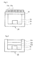
- Fig. 2 illustrates schematically a cross-section of a white light-emitting device according to Embodiment 2 of the present invention.
- a white light-emitting device 20 illustrated in the figure comprises a blue LED element 22 that is fixed to the bottom face of a recess that is provided in a package 21, a first wavelength conversion layer 23a that is disposed above the blue LED element 22 with an intervening space 24 in between, and a second wavelength conversion layer 23b that is stacked on the first wavelength conversion layer 23a.
- the first wavelength conversion layer 23a and the second wavelength conversion layer 23b are configured through dispersion of a particulate phosphor in a translucent matrix.
- the phosphor dispersed in the first wavelength conversion layer 23a comprises a Mn 4+ -activated fluoride complex phosphor that emits red light.
- the phosphor dispersed in the second wavelength conversion layer 23b comprises a Eu 2+ -activated alkaline earth silicon nitride phosphor that emits red light.
- a yellow phosphor may be incorporated in either wavelength conversion layer, but in terms of refractive index, the yellow phosphor preferably incorporated in the wavelength conversion layer that does not contain the Mn 4+ -activated fluoride complex phosphor.
- a green phosphor may be dispersed instead of, or in addition to, the yellow phosphor.
- the space 24 may be void, or part thereof may be filled with a translucent filler. Preferably, the entirety of the space 24 is filled with a translucent filler.
- the same materials as exemplified for the base material of the wavelength conversion layer 13 in Embodiment 1 may be used in the filler.
- Embodiment 1 The same phosphors as in Embodiment 1 are used in the phosphors contained in the blue LED element 22, the first wavelength conversion layer 23a and the second wavelength conversion layer 23b.
- the materials exemplified as the base material of the wavelength conversion layer 13 in Embodiment 1 can be used in the translucent matrix of the first wavelength conversion layer 23a and the second wavelength conversion layer 23b.
- the white light-emitting device 20 can be produced in accordance with the following procedure.
- thermosetting resin in a case where, for instance a thermosetting resin is used in the base of the translucent matrix of the first wavelength conversion layer 23a and of the second wavelength conversion layer 23b, the sheet molded body A and the sheet molded body B can be strongly bonded to each other through complete curing at the stage of forming the stack sheet, without complete curing of thermosetting resin at the stage of producing the two sheet molded bodies.
- thermoplastic resin is used as the base of the translucent matrix of the first wavelength conversion layer 23a and of the second wavelength conversion layer 23b, the two sheet molded bodies can be strongly bonded to each other through pressing at a temperature equal to or higher than the softening temperature of thermoplastic resin.
- the Mn 4+ -activated fluoride complex phosphor has a low refractive index. Therefore, a resin having a low refractive index is preferably used as the base of the translucent matrix of the first wavelength conversion layer 23a.
- a recommended resin herein is, for instance, a commercially-available dimethyl silicone resin having a refractive index 1.41.
- the Eu 2+ -activated alkaline earth silicon nitride phosphor is dispersed in the second wavelength conversion layer 23b.
- the Eu 2+ -activated alkaline earth silicon nitride phosphor is an inorganic phosphor.
- the yellow phosphor and/or green phosphor that are likewise dispersed are also preferably inorganic phosphors.
- the refractive index of inorganic phosphors, even when low, is of 1.6 or higher, and is for instance of 1.90 for YAG:Ce.
- the refractive index of the translucent matrix of the second wavelength conversion layer 23b is higher than that of the translucent matrix of the first wavelength conversion layer 23a, in order for light emitted by the phosphors not to be strongly trapped within phosphor particles.
- the refractive index of the translucent matrix of the second wavelength conversion layer 23b is higher than 1.50.
- Epoxy resins having a refractive index ranging from 1.53 to 1.57 are available.
- Diphenyldimethyl-based and phenylmethyl-based silicone resins having a refractive index of 1.52 are available.
- Polycarbonate resins, styrene resins and others have likewise refractive indices higher than 1.50.
- the refractive index of epoxy resins, silicone resins, acrylic resins, polycarbonate resins and the like can be increased up to about 1.8 through addition of high-refractive index inorganic nanoparticles that comprise, for instance, calcium oxide, cerium oxide, hafnium oxide, titanium oxide, zinc oxide, zirconium oxide or the like. If the refractive index of the translucent matrix exceeds the refractive index of the phosphor, however, efficiency may drop in some instances due to reflection of excitation light on the surface of the phosphor.
- all phosphors, except the Mn 4+ -activated fluoride complex phosphor, are dispersed in the second translucent matrix of high refractive index.
- the first wavelength conversion layer 23a and the second wavelength conversion layer 23b of Embodiment 2 are formed side by side on the surface of a transparent film 25 that comprises glass or a polymer as depicted in Fig.3 .
- Fig. 4 illustrates schematically a cross-section of a white light-emitting device according to Embodiment 3 of the present invention.
- a white light-emitting device 30 illustrated in the figure comprises a blue LED element 32 that is fixed to the bottom face of a recess that is provided in a package 31, a first wavelength conversion layer 33a that is formed so as to seal the blue LED element 32, a second wavelength conversion layer 33b stacked on the first wavelength conversion layer 33a, and a further third wavelength conversion layer 33c stacked on the second wavelength conversion layer 33b.
- the first wavelength conversion layer 33a, the second wavelength conversion layer 33b and the third wavelength conversion layer 33c are configured through dispersion of a particulate phosphor in a translucent matrix.
- the phosphor dispersed in the first wavelength conversion layer 33a comprises a Eu 2+ -activated alkaline earth silicon nitride phosphor that emits red light.
- the phosphor dispersed in the second wavelength conversion layer 33b is a yellow phosphor and/or a green phosphor.
- the phosphor dispersed in the third wavelength conversion layer 33c is a Mn 4+ -activated fluoride complex phosphor that emits red light.
- the same phosphors as in Embodiment 1 are used in the phosphors contained in the blue LED element 32, the first wavelength conversion layer 33a, the second wavelength conversion layer 33b and the third wavelength conversion layer 33c.
- the first wavelength conversion layer 33a, the second wavelength conversion layer 33b and the third wavelength conversion layer 33c are formed through pouring of a resin paste, having the phosphor dispersed therein, into the recess of the package 31, followed by curing.
- the base of the resin paste is for instance a silicone resin or an epoxy resin.
- a low-refractive index resin for instance a dimethyl silicone resin, is used as the base in the translucent matrix of the third wavelength conversion layer 33c in which the Mn 4+ -activated fluoride complex phosphor is dispersed.
- the refractive index of the translucent matrix of the first wavelength conversion layer 33a in which the Eu 2+ -activated alkaline earth silicon nitride phosphor is dispersed is higher than that of the third wavelength conversion layer 33c.
- an inorganic phosphor is dispersed in the second wavelength conversion layer 33b, and the refractive index of the translucent matrix is preferably higher than that of the third wavelength conversion layer 33c.
- n 1 >n 2 >n 3 denote respectively the refractive indices of the translucent matrices of the first wavelength conversion layer 33a, the second wavelength conversion layer 33b and the third wavelength conversion layer 33c.
- the silicone resin that is the base of the composition is of low-refractive index type, with a refractive index ranging from 1.41 to less than 1.45.
- the KSNAF used in the present experimental example was synthesized according to the following procedure. Firstly, 3.4712 g of K 2 MnF6 and 1.3252 g of NaF were dissolved in a mixed solution of 40 ml of an H 2 SiF 6 aqueous solution (33 wt%) and 160 ml of hydrofluoric acid (47.3 wt%), to prepare a solution (solution A). Next, the solution A was added to a solution (solution B) resulting from dissolving 18.92 g of KHF 2 and 8.16 g of K 3 AlF 6 in 320 ml of hydrofluoric acid (47.3 wt%). The solution B was held at 26°C, and yellow crystals precipitated upon addition, under stirring, of the solution A. The yellow crystals were filtered off using No. 5C filter paper, were washed thrice thereafter with 50 ml of ethanol, and were dried at 150°C for 2 hours, to yield 19.6 g of a phosphor (KSNAF).
- KSNAF
- Y 3 Al 5 O 12 :Ce (abbreviation YAG) and La 3 Si 6 N 11 :Ce (abbreviation LSN) were used as yellow phosphors, and KSNAF, KSF and Sr x Ca 1-x AlSiN 3 :Eu (abbreviation SCASN) were used as red phosphors.
- YAG or LSN was used as a yellow phosphor as in the examples, but only one from among KSNAF or KSF and SCASN was used as the red phosphor.
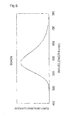
- Fig. 5 and Fig. 6 illustrate the emission spectra of KSNAF and SCASN.
- the emission peak wavelength 617 nm of SCASN is 14 nm shorter than the maximum emission peak wavelength 631 nm of KSNAF, and is positioned at a longer wavelength than the peak wavelength 613 nm of the comparatively broad-emission band of KSNAF on the shorter wavelength side of the maximum emission peak.
- Table 2 gives the blending ratio of the various phosphors in the silicone resin compositions used to produce the white LEDs according to the examples and comparative examples.
- Example 2 Phosphor type Phosphor blending ratio [wt%] Emission color Abbreviation Example 1 Yellow YAG 7.5 Red KSNAF 11.5 Red SCASN 1.3 Comparative Example 1 Yellow YAG 6.0 Red KSNAF 38.4 Comparative Example 2 Yellow YAG 7.7 Red SCASN 2.4 Example 2 Yellow LSN 5.5 Red KSF 24.7 Red SCASN 0.5 Comparative Example 3 Yellow LSN 4.4 Red KSF 31.7 Comparative Example 4 Yellow LSN 8.1 Red SCASN 2.4
- the blending ratio of KSNAF in the silicone resin composition had to be increased to 38.4 wt%, and the blending ratio of KSF to 31.7 wt%, in Comparative Examples 1 and 3 where KSNAF or KSF alone was used as the red phosphor, in order to produce a white LED having a correlated color temperature of about 2700 K.
- the blending ratio of KSNAF could be reduced to 11.5 wt%, and the blending ratio of KSF to 24.7 wt%, through the concomitant use of a small amount of SCASN.
- the viscosity of the silicone resin paste used for sealing the white LEDs in Examples 1 and 2 dropped significantly with respect to the silicone resin paste used in Comparative Examples 1 and 3.
- Table 3 gives the emission characteristics, upon application of a 20 mA current, of the white LEDs of Examples 1 to 2, and Comparative Examples 1 to 4.
- Fig. 7 illustrates the emission spectrum of the white LED according to Example 1.
- Dripping of the target amount of the resin composition was complete over a short time (within 5 seconds). Dispensing using a dispenser was possible at ordinary pressure. No spraying out of a nozzle occurred even when the pressure was raised. C: a long time (10 seconds or longer) has to elapse until complete dripping of the target amount of resin composition upon scooping of the resin composition with a spatula and transfer to the package. Dispensing using a dispenser was not possible at an ordinary pressure. Spraying out of a nozzle occurred when the pressure was raised.
- the conversion efficiency given in Table 3 is a value resulting from dividing the luminous flux of the white LEDs (upon application of 20 mA) by the bare chip output (upon application of 20 mA) of the blue LED element that is mounted in the 3528SMD-type PPA resin package, as measured before sealing with a silicone resin composition.
- Table 3 shows, the conversion efficiency of the white LEDs according to Examples 1 to 2 and Comparative Examples 1 to 4 are substantially identical.
- the color rendering properties of the white LEDs, an indicator of which is the average color rendering index Ra are best in Comparative Examples 1 and 3, next in Examples 1 and 2, and poorest in Comparative Examples 2 and 4.
- the average color rendering index Ra in the white LEDs of Examples 1 and 2 is 82.
- the white LEDs satisfy the required illumination levels in, for instance, homes, hotels, restaurants, shops, offices, schools, hospitals and factories where precision work is performed.
- the color rendering properties in the white LEDs of Comparative Examples 2 and 4 where no KSNAF or KSF is used in the red phosphor, fail to reach these levels.
- the simulation was carried out as follows, using an emission spectrum measured upon application of a 20 mA current to various white LED samples.
- a synthetic spectrum was created by selecting one type of each white light-emitting device corresponding to the white LED that uses 100% of KSF, as a red phosphor, plus LSN, of Comparative Example 3, and the white LED that uses 100% of SCASN, as a red phosphor, plus LSN, of Comparative Example 4, and by adding the respective emission spectra, at a ratio of n:(10-n).
- the CIE chromaticity coordinate value (x,y), the correlated color temperature Tcp and the average color rendering index Ra for the created synthetic spectrum were worked out by calculation. Changes in the luminous flux ratio of the two types of white LED were simulated by varying 'n' in the above ratio, in increments of 1, from 1 to 9.
- Example 4 Phosphor type Phosphor blending ratio [wt%] Content ratio % of SCASN with respect to total KSF+SCASN [wt%/wt%] Emission color Abbreviation Comparative Example 5 Yellow LSN 4.4 0.0 Red KSF 31.7 Red SCASN 0.0 Example 3 Yellow LSN 4.8 0.8 Red KSF 28.5 Red SCASN 0.2 Example 4 Yellow LSN 5.1 1.9 Red KSF 25.4 Red SCASN 0.5 Example 5 Yellow LSN 5.5 3.1 Red KSF 22.2 Red SCASN 0.7 Example 6 Yellow LSN 5.9 4.8 Red KSF 19.0 Red SCASN 1.0 Example 7 Yellow LSN 6.3 7.0 Red KSF 15.9 Red SCASN 1.2 Example 8 Yellow LSN 6.
- the white light-emitting device of the invention of the present application can be used in an illumination device such as light bulbs, downlights, line illumination and the like.
Abstract
Description
- The present invention relates to a white light-emitting device that is provided with a Mn4+-activated fluoride complex phosphor that emits red light, and with an LED (light-emitting diode) element that is an excitation source of the phosphor.
- Known red phosphors having a narrow-band emission spectrum include Mn4+-activated fluoride complex phosphors (Patent Document 1). Light emitted by such phosphors comprises substantially no component of wavelength longer than the main emission peak wavelength (ordinarily, 620 to 640 nm), i.e. substantially no deep-red component of low luminosity factor. Also, such phosphors absorb substantially no light having a wavelength of 490 nm or longer, i.e. substantially no light emitted by a green phosphor or a yellow phosphor. Such properties are deemed to be ideal properties of a red phosphor for white LEDs for illumination where higher efficiency is desirable. A high-efficiency white LEDs that emits warm white light and in which K2TiF6:Mn, which is a Mn4+-activated fluoride complex phosphor, is concomitantly used with a broad-band yellow phosphor Tb3Al5O12:Ce, has actually been reported (Patent Document 2).
-
- Patent Document 1:
US Patent Publication No. 3576756 - Patent Document 2:
US Patent Application Publication No. 2006/0169998 - The inventors had produced trial white LEDs that emit warm white light, using KSNAF (described in detail further on), which is a Mn4+-activated fluoride complex phosphor, and a yellow phosphor YAG:Ce, and had found that the white LED afforded superior luminous efficiency. In this trial production, a blue LED element was sealed using a paste resulting from adding powders of KSNAF and YAG:Ce to a liquid silicone resin. However, KSNAF had to be added to a high concentration in the silicone resin in order to achieve the target chromaticity, and the viscosity of the paste became very high as a result.
- High paste viscosity results in poorer transportability (due to lower fluidity and less precise dosing), occurrence of cobwebbing, more difficult defoaming, as well as difficulties in achieving a homogeneous phosphor dispersion, all of which translates into a lower manufacturing efficiency of the white LED. It is deemed, therefore, that it would be possible to produce more efficiently a white LED that uses a Mn4+-activated fluoride complex phosphor if the used amount of the phosphor could be reduced.
- Also, costly fluorine-containing compounds are used to produce the Mn4+-activated fluoride complex phosphor, and hence reducing the amount of the phosphor used would also be advantageous in terms of cost.
- Therefore, the present invention provides a technology that allows reducing, without loss of luminous efficiency, the amount of Mn4+-activated fluoride complex phosphor that is used, in a white light-emitting device that comprises the Mn4+-activated fluoride complex phosphor and an LED element that is an excitation source of the phosphor.
- The gist of the present invention is as follows.
- (1) A white light-emitting device comprising: an LED element that emits blue light; and a resin composition that contains a phosphor that emits yellow light and/or a phosphor that emits green light through wavelength conversion of light emitted by the LED element that emits blue light, and a phosphor that emits red light through wavelength conversion of light emitted by the LED element that emits blue light,
wherein the phosphor that emits red light contains at least a Mn4+-activated fluoride complex phosphor and an Eu2+-activated alkaline earth silicon nitride phosphor, and
a content ratio of the Eu2+-activated alkaline earth silicon nitride phosphor with respect to the total of the Mn4+-activated fluoride complex phosphor and Eu2+-activated alkaline earth silicon nitride phosphor contained in the resin composition ranges from 0.5 wt% to 14.0 wt%. - (2) A white light-emitting device comprising: an LED element; and a resin composition that contains a phosphor that emits blue light through wavelength conversion of light emitted by the LED element, a phosphor that emits yellow light and/or a phosphor that emits green light through wavelength conversion of light emitted by the LED element, and a phosphor that emits red light through wavelength conversion of light emitted by the LED element,
wherein the phosphor that emits red light contains at least a Mn4+-activated fluoride complex phosphor and an Eu2+-activated alkaline earth silicon nitride phosphor, and
a content ratio of the Eu2+-activated alkaline earth silicon nitride phosphor with respect to the total of the Mn4+-activated fluoride complex phosphor and Eu2+-activated alkaline earth silicon nitride phosphor contained in the resin composition ranges from 0.5 wt% to 14.0 wt%. - (3) The white light-emitting device according to (1) or (2), wherein λR1-20≤λR2≤λR1+30 is satisfied where λR1 nm is an emission peak wavelength of the Mn4+-activated fluoride complex phosphor and λR2 nm is an emission peak wavelength of the Eu2+-activated alkaline earth silicon nitride phosphor.
- (4) The white light-emitting device according to (3), wherein a maximum peak wavelength in an emission spectrum of the Eu2+-activated alkaline earth silicon nitride phosphor ranges from 600 to 630 nm.
- (5) The white light-emitting device according to (3) or (4), wherein the Mn4+-activated fluoride complex phosphor is KSF or KSNAF.
- (6) The white light-emitting device according to any one of (3) to (5), wherein the Eu2+-activated alkaline earth silicon nitride phosphor is SryCa1-yAlSiN3:Eu.
- (7) The white light-emitting device according to any one of (1) to (6), wherein the phosphor that emits yellow light is a (Y1-u, Gdu)3(Al1-vGav)5O12:Ce, Eu phosphor (where u and v are 0≤u≤0.3 and 0≤v≤0.5, respectively) or Ca1.5xLa3-xSi6N11:Ce (where x is 0≤x≤1).
- (8) The white light-emitting device according to any one of (1) to (7), wherein the Mn4+-activated fluoride complex phosphor is dispersed in a cured product of a resin paste.
- (9) The white light-emitting device according to (8), wherein a base resin of the resin paste is a silicone resin.
- (10) The white light-emitting device according to any one of (1) to (9), wherein a correlated color temperature of emitted white light ranges from 1600 to 4000 K.
- (11) The white light-emitting device according to any one of (1) to (9), wherein a correlated color temperature of emitted white light ranges from 2500 to 3500 K.
- (12) The white light-emitting device according to any one of (1) to (11), wherein a blending proportion of the Mn4+-activated fluoride complex phosphor contained in the resin composition ranges from 10 wt% to 50 wt%, and
a blending proportion of the Eu2+-activated alkaline earth silicon nitride phosphor contained in the resin composition ranges from 0.1 wt% to 5.0 wt%. - (13) A white light-emitting device, comprising: an LED element that emits blue light; a phosphor that emits yellow light and/or a phosphor that emits green light through wavelength conversion of light emitted by the LED element that emits blue light; and a phosphor that emits red light through wavelength conversion of light emitted by the LED element that emits blue light; or comprising: an LED element; a phosphor that emits blue light through wavelength conversion of light emitted by the LED element; a phosphor that emits yellow light and/or a phosphor that emits green light through wavelength conversion of light emitted by the LED element; and a phosphor that emits red light through wavelength conversion of light emitted by the LED element,
wherein the phosphor that emits red light contains a Mn4+-activated fluoride complex phosphor dispersed in a first translucent matrix and an Eu2+-activated alkaline earth silicon nitride phosphor dispersed in a second translucent matrix, and
a content ratio of the Eu2+-activated alkaline earth silicon nitride phosphor with respect to the total of the Mn4+-activated fluoride complex phosphor and Eu2+-activated alkaline earth silicon nitride phosphor ranges from 0.5 wt% to 14.0 wit%. - (14) The white light-emitting device according to (13), wherein a refractive index of the first translucent matrix is lower than a refractive index of the second translucent matrix.
- (15) The white light-emitting device according to (14), wherein all the phosphors, except the Mn4+-activated fluoride complex phosphor, are dispersed in the second translucent matrix.
- (16) The white light-emitting device according to any one of (13) to (15), wherein the first translucent matrix is a cured product of a resin paste.
- (17) The white light-emitting device according to (16), wherein a base resin of the resin paste is a silicone resin.
- (18) The white light-emitting device according to (17), wherein a refractive index of the silicone resin is smaller than 1.45.
- (19) The white light-emitting device according to any one of (13) to (18), wherein a correlated color temperature of emitted white light ranges from 1600 to 4000 K.
- (20) The white light-emitting device according to any one of (13) to (19), wherein a correlated color temperature of emitted white light ranges from 2500 to 3500 K.
- (21) A white light-emitting device comprising: an LED element that emits blue light; and a resin composition that contains a phosphor that emits yellow light and/or a phosphor that emits green light through wavelength conversion of light emitted by the LED element that emits blue light, and a phosphor that emits red light through wavelength conversion of light emitted by the LED element that emits blue light,
wherein the phosphor that emits red light contains at least a red phosphor having a narrow-band emission spectrum such that a maximum emission peak thereof ranges from 600 nm to 660 nm and the full width at half maximum of a red emission peak is 20 nm or less, and a red phosphor having a broad-band emission spectrum such that a maximum emission peak thereof ranges from 600 nm to 660 nm and the full width at half maximum of a red emission peak is 80 nm or more, and
a content ratio of the red phosphor having the broad-band emission spectrum with respect to the total of the red phosphor having the narrow-band emission spectrum and the red phosphor having the broad-band emission spectrum that are contained in the resin composition ranges from 0.5 wt% to 14.0 wt%. - (22) A white light-emitting device comprising: an LED element; and a resin composition that contains a phosphor that emits blue light through wavelength conversion of light emitted by the LED element, a phosphor that emits yellow light and/or a phosphor that emits green light through wavelength conversion of light emitted by the LED element, and a phosphor that emits red light through wavelength conversion of light emitted by the LED element,
wherein the phosphor that emits red light contains at least a red phosphor having a narrow-band emission spectrum such that a maximum emission peak thereof ranges from 600 nm to 660 nm and the full width at half maximum of a red emission peak is 20 nm or less, and a red phosphor having a broad-band emission spectrum such that a maximum emission peak thereof ranges from 600 nm to 660 nm and the full width at half maximum of a red emission peak is 80 nm or more, and
a content ratio of the red phosphor having the broad-band emission spectrum with respect to the total of the red phosphor having the narrow-band emission spectrum and the red phosphor having the broad-band emission spectrum that are contained in the resin composition ranges from 0.5 wt% to 14.0 wt%. - (23) The white light-emitting device according to (21) or (22), wherein a blending proportion of the red phosphor having the narrow-band emission spectrum and contained in the resin composition ranges from 10 wt% to 50 wt%.
- (24) The white light-emitting device according to any one of (21) to (23), wherein a blending proportion of the red phosphor having the broad-band emission spectrum and contained in the resin composition ranges from 0.1 wt% to 5.0 wt%.
- (25) An illumination device, comprising the white light-emitting device according to any one of (1) to (24).
- The embodiments that are set forth as the gist of the present invention make it possible to reduce the used amount of red phosphor having a narrow-band emission spectrum, for instance a Mn4+-activated fluoride complex phosphor, without loss of luminous efficiency, in a white light-emitting device of high color rendering and that is provided with a red phosphor having a narrow-band emission spectrum, for instance a Mn4+-activated fluoride complex phosphor or the like, and with an LED element that is an excitation source of the phosphor. Accordingly, a white light-emitting device can be obtained that boasts high production efficiency, by causing the viscosity of the resin composition that contains the red phosphor having a narrow-band emission spectrum, such as a Mn4+-activated fluoride complex phosphor or the like, to lie within an appropriate viscosity range.
-
-
Fig. 1 illustrates schematically a cross-sectional structure of a white light-emitting device according to an embodiment of the present invention; -
Fig. 2 illustrates schematically a cross-sectional structure of a white light-emitting device according to an embodiment of the present invention; -
Fig. 3 illustrates schematically a cross-sectional structure of a white light-emitting device according to an embodiment of the present invention; -
Fig. 4 illustrates schematically a cross-sectional structure of a white light-emitting device according to an embodiment of the present invention; -
Fig. 5 illustrates an emission spectrum of a KSNAF phosphor; -
Fig. 6 illustrates an emission spectrum of a SCASN phosphor; -
Fig. 7 illustrates an emission spectrum of a white LED according to Example 1 of the present invention; -
Fig. 8 is a chromaticity diagram (CIE 1931); and -
Fig. 9 illustrates changes in color rendering properties upon variation of a ratio of mixed light in a white light-emitting device according to a simulation in an example of the present invention. - In the invention and in the present description, light having a color that exhibits a deviation Duv of -20 to +20 from the black-body radiation locus is referred to as white light. The definition of Duv (= 1000 duv) conforms to JIS Z 8725:1999 "Method for Determining Distribution Temperature and Color Temperature or Correlated Color Temperature of Light Sources".
- In one embodiment thereof, the present invention provides a white light-emitting device that comprises a phosphor, and an LED element that is an excitation source of the phosphor. The white light-emitting device comprises an LED element that emits blue light, a phosphor that emits yellow light (hereafter also referred to as yellow phosphor) and a phosphor that emits red light (hereafter also referred to as red phosphor) through wavelength conversion upon being excited, directly or indirectly, by light emitted by the LED element, such that white light can be emitted that is combined light of the light respectively emitted by the blue LED element, the phosphor that emits yellow light and the phosphor that emits red light. Alternatively, the white light-emitting device may comprise an LED element that emits light of a shorter wavelength than blue, for instance, a near-ultraviolet LED element or a purple LED element, and a phosphor that emits blue light(hereafter also referred to as blue phosphor), a phosphor that emits yellow light and a phosphor that emits red light, through wavelength conversion upon being excited, directly or indirectly, by the light emitted by the LED element, such that white light can be emitted that is combined light of the light respectively emitted by the phosphor that emits blue light, the phosphor that emits yellow light and the phosphor that emits red light. In these white light-emitting devices, a phosphor that emits green light (hereafter also referred to as green phosphor), through wavelength conversion when being excited directly or indirectly by light emitted by the LED element, may be used instead of, or in addition to, the yellow phosphor.
- An LED element having a light-emitting structure formed by various types of semiconductor, for instance GaN-based semiconductors, ZnO-based semiconductors, SiC-based semiconductor or the like, can be used in the white light-emitting device according to the present invention. The LED element may be fixed to a package such as a bullet-type package, an SMD-type package or the like, or may be directly fixed to a circuit board, as in the case of a chip-on-board light-emitting device. The way in which the LED element and the phosphors are optically coupled is not limited, and a transparent medium (such as air) may be simply interposed between the LED element and the phosphors; alternatively, an optical element such as a lens, an optical fiber, a waveguide, a reflective mirror or the like may be interposed between the LED element and the phosphors.
- Particulate phosphors are preferably used in the white light-emitting device of the present invention, but the white light-emitting device is not limited thereto, and, for instance, the phosphors may be, in part, a light-emitting ceramic that contains a phosphor phase in the ceramic structure. Particulate phosphors are ordinarily dispersed in a translucent matrix having a polymer as a dispersion medium, in order for the phosphors to be immobilized thereby, but the phosphors may alternatively be deposited, by electrodeposition or some other method, on the surface of an appropriate member. Structures in which phosphor particles are dispersed in a translucent matrix are typically formed by curing a resin paste in which a particulate phosphor has been dispersed. Various structures can be adopted herein, for instance a structure in which the LED element is embedded in a cured product of such a paste, a structure wherein such a cured product covers, in the form of a film, part of the surface of the LED element, or a structure wherein a film comprising such a cured product is disposed at a site spaced apart from the LED element.
-
Fig. 1 illustrates schematically a cross-section of a white light-emitting device according toEmbodiment 1 of the present invention. A white light-emittingdevice 10 illustrated in the figure comprises ablue LED element 12 that is fixed to the bottom face of a recess that is provided in apackage 11, and awavelength conversion layer 13 that seals theblue LED element 12. A particulate yellow phosphor and red phosphor (not shown) are substantially homogeneously dispersed in the interior of thewavelength conversion layer 13. - Although not shown in the figure, a known wiring pattern is provided in the
package 11. Theblue LED element 12 has an emission peak wavelength at 440 to 470 nm. The material and structure of theblue LED element 12 are not particularly limited, but, preferably, theblue LED element 12 is for instance a gallium nitride-based LED element that uses InGaN in a light-emitting layer. Preferably, the emission peak wavelength of the blue LED element is set in such a manner that the difference vis-à-vis the peak wavelength of the excitation spectrum of the Mn4+-activated fluoride complex phosphor that is dispersed in thewavelength conversion layer 13 is no greater than 5 nm. Theblue LED element 12 may be provided in the form of a plurality of elements. - The
blue LED element 12 emits light upon application of current to theblue LED element 12 via the wiring pattern that is provided in thepackage 11; the yellow phosphor and the red phosphor emit light upon absorption of light emitted by theblue LED element 12. As a result, white light, resulting from mixing of light of dissimilar colors respectively emitted by the blue LED, the yellow phosphor and the red phosphor, is emitted out of the white light-emittingdevice 10. - The yellow phosphor that is dispersed in the
wavelength conversion layer 13 is a phosphor the emission color whereof is classified as ""YELLOW GREEN", "GREENISH YELLOW", "YELLOW", or "YELLOWISH ORANGE" in the xy chromaticity diagram (CIE 1931) depicted inFig. 8 . The main emission peak wavelength of the yellow phosphor is ordinarily 530 nm or longer, preferably 540 nm or longer, and particularly preferably 550 nm or longer, and is ordinarily 620 nm or shorter, preferably 600 nm or shorter, and particularly preferably 580 nm or shorter. - Any organic or inorganic yellow phosphor that emits light upon absorption of blue light can be used, but inorganic phosphors are superior in terms of durability. Recommended such phosphors include, for instance, phosphors having Ce3+ as an activator and a garnet-type oxide crystal as a base, represented by the general formula (Y1-u, Gdu)3(Al1-vGav)5O12:Ce, Eu (wherein u and v are 0≤u≤0.3 and 0≤v≤0.5, respectively), for instance (Y, Gd)3Al5O12:Ce, Tb3Al5O12:Ce or the like; or phosphors having Ce3+ as an activator and having a lanthanum silicon nitride crystal as a base, for instance La3Si6N11: Ce, Ca1.5xLa3xSi6N11:Ce (where x is 0≤x≤1) or the like. These yellow phosphors are excited efficiently excited by blue light. Yellow phosphors having Eu2+ as an activator, such as (Ba, Sr, Ca)2SiO4:Eu, α-Sialon:Eu or the like, can be excited efficiently not only by blue light, but also by near-ultraviolet light and purple light.
- In the
wavelength conversion layer 13 there can be dispersed a green phosphor instead of, or in addition to, the yellow phosphor. The term "green phosphor" denotes a phosphor that emits light having a color that is classified as "GREEN" or "YELLOWISH GREEN" in the xy chromaticity diagram (CIE 1931) depicted inFig. 8 . The main emission peak wavelength of the green phosphor is ordinarily 500 nm or longer, preferably 510 nm or longer, and particularly preferably 520 nm or longer, and is ordinarily 580 nm or shorter, preferably 570 nm or shorter, and particularly preferably 560 nm or shorter. - Any organic or inorganic green phosphor that emits light upon absorption of blue light can be used, but inorganic phosphors are superior in terms of durability. Green phosphors that use Eu2+ or Ce3+ as an activator are recommended herein. Green phosphors that use Eu2+ as an activator include green phosphors that have, as a base, a crystal that comprises an alkaline earth silicate, an alkaline earth silicon oxynitride, or Sialon. Specific examples of green phosphors having an alkaline earth silicate crystal as a base include, for instance, (Ba, Ca, Sr, Mg)2SiO4:Eu, (Ba,Sr,Ca)2(Mg,Zn)Si2O7:Eu or the like. Specific examples of green phosphors using an alkaline earth silicon oxynitride crystal as a base include, for instance, (Ba, Ca, Sr)3Si6O12N2:Eu, (Ba, Ca, Sr)3Si6O9N4:Eu, (Ca,Sr,Ba)Si2O2N2:Eu or the like. Specific examples of green phosphors using a Sialon crystal as a base include, for instance, β-Sialon: Eu, Sr3Si13Al3O2N21:Eu, Sr5Al5Si21O2N35: Eu or the like. These green phosphors can be excited efficiently by blue light, and also by near-ultraviolet and purple light.
- Examples of green phosphors that use Ce3+ as an activator include, for instance, green phosphors having a garnet-type oxide crystal as a base, for instance Ca3(Sc,Mg)2Si3O12:Ce, or green phosphors having, as a base, a crystal of a scandate of an alkaline earth metal, for instance CaSc2O4:Ce. These green phosphors are efficiently excited by blue light.
- The red phosphor that is dispersed in the
wavelength conversion layer 13 is a phosphor the emission color whereof is classified as "RED", "REDDISH ORANGE" or "ORANGE" in the xy chromaticity diagram (CIE 1931) depicted inFig. 8 . As the red phosphor there is used a Mn4+-activated fluoride complex phosphor and/or a Eu2+-activated alkaline earth silicon nitride phosphor. The amount of Mn4+-activated fluoride complex phosphor that is added to thewavelength conversion layer 13 can be significantly reduced by using concomitantly a small amount of a Eu2+-activated alkaline earth silicon nitride phosphor, as the red phosphor, with substantially no drop in luminous efficiency as compared with an instance where a Mn4+-activated fluoride complex phosphor alone is used. This effect is prominent when the white light emitted by the white light-emittingdevice 10 is warm white light having a significant amount of red component (color temperature ranging from 1600 to 4000 K, preferably from 2500 to 3500 K). - Herein, Mn4+-activated fluoride complex phosphors are phosphors having Mn4+ as an activator, and having a fluoride complex salt of an alkali metal, an amine or an alkaline earth metal, as a base crystal. The coordination center in the fluoride complex that forms the base crystal is a trivalent metal (B, Al, Ga, In, Y, Sc or lanthanoid), a tetravalent metal (Si, Ge, Sn, Ti, Zr, Re, Hf) or a pentavalent metal (V, P, Nb or Ta), with 5 to 7 fluorine atoms coordinated around the coordination center.
- A preferred Mn4+-activated fluoride complex phosphor is herein A2MF6:Mn having a hexafluoro complex salt of an alkali metal as a base crystal (A is one or more types selected from among Li, Na, K, Rb, Cs and NH4, and M is one or more types selected from among Ge, Si, Sn, Ti and Zr). Particularly preferred among the foregoing is a Mn4+-activated fluoride complex phosphor wherein A is one or more types selected from among K (potassium) and Na (sodium), and M is Si (silicon) or Ti (titanium), for instance K2SiF6:Mn (KSF), KSNAF (K2Si1xNaxAlxF6:Mn) in which some of the constituent elements of KSF (preferably, 10 mol% or less) are replaced by Al and Na, or K2TiF6:Mn (KTF).
- In KSNAF, some of the constituent atoms of KSF (preferably, 10 mol% or less) are replaced by Al and Na. Herein, KSF and KSNAF can be produced in accordance with a method that involves using K2SiF6, A3AlF6, NaF, KF, K2MnF6, KMnO4, K2MnCl6 or the like as starting material compounds, adding these starting material compounds to hydrofluoric acid in proper proportions, causing the compounds to dissolve and react, under stirring, and adding thereafter a poor solvent of the phosphor, to cause the phosphor to precipitate (antisolvent precipitation). This method may be carried out in the same way as in the method disclosed in
Patent Document 1; also, a high-luminance phosphor having a larger particle size can be obtained by slowing down the addition rate of the poor solvent. - Examples of combinations of starting material compounds that can be used in the production of KSF or KSNAF by antisolvent precipitation are given below.
- 1) combination of K2SiF6, K2NaAlF6 and K2MnF6.
- 2) combination of K2SiF6, K3AlF6, NaF and K2MnF6.
- 3) combination of K2SiF6, K3AlF6, Na3AlF6 and K2MnF6.
- 4) combination of K2SiF6, KF, Na3AlF6 and K2MnF6.
- 5) combination of K2SiF6, K2NaAlF6 and KMnO4.
- 6) combination of K2SiF6, K3AlF6, NaF and KMnO4.
- 7) combination of K2SiF6, K3AlF6, Na3AlF6 and KMnO4.
- 8) combination of K2SiF6, KF, Na3AlF6 and KMnO4.
- 9) combination of K2SiF6 and K2MnCl6.
- 10) combination of K2SiF6, K3AlF6, NaF and K2MnCl6.
- 11) combination of K2SiF6, K3AlF6, Na3AlF6 and K2MnCl6.
- Specific examples of Eu2+-activated alkaline earth silicon nitride phosphors include, for instance, (Ca,Sr,Ba)AlSiN3:Eu, (Ca, Sr, Ba)2Si5N8:Eu, SrAlSi4N7: Eu, (CaAlSiN3)1-x(Si(3n+2)/4NnO)x:Eu and the like. Herein, (CaAlSiN3)1-x(Si(3n+2)/4NnO)x:Eu has a base in the form of a solid solution crystal of CaAlSiN3 and Si(3n+2)/4NnO, and hence is regarded as an alkaline earth silicon nitride phosphor.
- Preferably, the maximum peak wavelength of the emission spectrum of the Eu2+-activated alkaline earth silicon nitride phosphor ranges from 600 to 630 nm. Such Eu2+-activated alkaline earth silicon nitride phosphors are preferred in that they exhibit high color rendering properties and high luminosity factor as red phosphors, and hence can be used for forming a light-emitting device of high luminous efficiency.
- Preferably, the peak wavelengths of the Mn4+-activated fluoride complex phosphor and the Eu2+-activated alkaline earth silicon nitride phosphor that are contained, as red phosphors, in the
wavelength conversion layer 13, obey a specific relationship. Specifically it is preferable that λR1-20≤λR2≤λR1+30 is satisfied where λR1 nm denotes the emission peak wavelength of the Mn4+-activated fluoride complex phosphor and λR2 nm denotes the emission peak wavelength of the Eu2+-activated alkaline earth silicon nitride phosphor. It is more preferable that λR1-20≤λR2≤λR1 is satisfied. A red phosphor that satisfies such a requirement exhibits high color rendering properties and high luminosity factor as a red phosphor, and hence a white light-emitting device can be achieved that has high luminous efficiency. - A transparent resin can be used as the base material of the
wavelength conversion layer 13. Examples of resins include, for instance, various types of thermoplastic resins, thermosetting resins and photocurable resins, specific instances whereof include, for instance, methacrylic resins (polymethyl methacrylate or the like), styrene resins (polystyrene, styrene-acrylonitrile copolymers or the like), polycarbonate resins, polyester resins, phenoxy resins, butyral resins, polyvinyl alcohol, cellulose resins (ethyl cellulose, cellulose acetate, cellulose acetate butyrate and the like), epoxy resins, phenolic resins and silicone resins. - The base material of the
wavelength conversion layer 13, made up of a resin composition, contains at least the Mn4+-activated fluoride complex phosphor and the Eu2+-activated alkaline earth silicon nitride phosphor.
The amount of Mn4+-activated fluoride complex phosphor that is added to thewavelength conversion layer 13 can be significantly reduced by using concomitantly a small amount of a Eu2+-activated alkaline earth silicon nitride phosphor, as a red phosphor, in the resin composition, with substantially no drop in luminous efficiency as compared with an instance where a Mn4+-activated fluoride complex phosphor alone is used. Specifically, effects are elicited when the content ratio of the Eu2+-activated alkaline earth silicon nitride phosphor with respect to the total of the Mn4+-activated fluoride complex phosphor and Eu2+-activated alkaline earth silicon nitride phosphor contained in the resin composition ranges from 0.5 wt% to 14.0 wt%. Preferably, the content ratio of the Eu2+-activated alkaline earth silicon nitride phosphor is 0.5 wt% or higher, more preferably 1.5 wt% or higher, and yet more preferably 2.0 wt% or higher, and is preferably 14.0 wt% or lower, more preferably 10.0 wt% or lower, yet more preferably 6.0 wt% or lower. - The blending proportion of the Mn4+-activated fluoride complex phosphor contained in the resin composition ranges preferably from 10 wt% to 50 wt%, more preferably from 15 wt% to 40 wt%, and yet more preferably from 16 wt% to 30 wt%.
The blending proportion of the Eu2+-activated alkaline earth silicon nitride phosphor contained in the resin composition is preferably 0.1 wt% or higher, more preferably 0.2 wt% or higher, and yet more preferably 0.3 wt% or higher, and is preferably 5.0 wt% or lower, more preferably 3.0 wt% or lower, and yet more preferably 2.0 wt% or lower. - In the present invention it is possible to reduce the blending proportion of the Mn4+-activated fluoride complex phosphor, as described above, and hence the viscosity of the resin composition is an appropriate one. If the viscosity is excessively high, a long time (10 seconds or longer) has to elapse until complete dripping of a target amount of resin composition upon scooping of the resin composition with a spatula and transfer of the resin composition to the package. Also, dispensing may fail to take place at an ordinary pressure using a dispenser, and/or the resin composition may fly off a nozzle if the pressure is increased, all of which detracts from the manufacturing efficiency of the white light-emitting device. If the viscosity is too low, on the other hand, handling becomes difficult during production of the light-emitting device.
- In another configuration, the base material of the
wavelength conversion layer 13 is made up of a resin composition that comprises at least a red phosphor having a narrow-band emission spectrum such that the maximum emission peak ranges from 600 nm to 660 nm and the full width at half maximum of the red emission peak is 20 nm or less, and a red phosphor having a broad-band emission spectrum such that the maximum emission peak ranges from 600 nm to 660 nm, and the full width at half maximum of the red emission peak is 80 nm or more.
The amount of red phosphor that has a narrow-band emission spectrum and that is added to thewavelength conversion layer 13 can be significantly reduced by using concomitantly, in the resin composition, also a small amount of the red phosphor having a broad-band emission spectrum, as a red phosphor, in addition to the red phosphor having a narrow-band emission spectrum, with substantially no drop in luminous efficiency as compared with an instance where there is used only the red phosphor having a narrow-band emission spectrum. Specifically, effects are elicited when the content ratio of the red-colored phosphor having a broad-band emission spectrum ranges from 0.5 wt% to 14.0 wt% with respect to the total of the red phosphor having a narrow-band emission spectrum and the red-colored phosphor having a broad-band emission spectrum that are contained in the resin composition. The content ratio of the red-colored phosphor having a broad-band emission spectrum is preferably 0.5 wt% or higher, more preferably 1.5 wt% or higher, and yet more preferably 2.0 wt% or higher, and is preferably 14.0 wt% or lower, more preferably 10.0 wt% or lower, yet more preferably 6.0 wt% or lower. - The blending proportion of the red phosphor having a narrow-band emission spectrum and contained in the resin composition ranges preferably from 10 wt% to 50 wt%, more preferably from 15 wt% to 40 wt%, and yet more preferably from 16 wt% to 30 wt%.
The blending proportion of the red-colored phosphor having a broad-band emission spectrum and contained in the resin composition is preferably 0.1 wt% or higher, more preferably 0.2 wt% or higher and yet more preferably 0.3 wt% or higher, and is preferably 5.0 wt% or lower, more preferably 3.0 wt% or lower, and yet more preferably 2.0 wt% or lower. - In the present invention, it is possible to reduce the blending proportion of the red phosphor having a narrow-band emission spectrum, as described above, and hence the viscosity of the resin composition is an appropriate one. If the viscosity is excessively high, a long time (10 seconds or longer) has to elapse until complete dripping of a target amount of resin composition upon scooping of the resin composition with a spatula and transfer of the resin composition to the package. Also, dispensing may fail to take place at an ordinary pressure using a dispenser, and/or the resin composition may fly off a nozzle if the pressure is increased, all of which detracts from the manufacturing efficiency of the white light-emitting device. If the viscosity is too low, on the other hand, handling becomes difficult during production of the light-emitting device.
- Preferably, the maximum peak wavelength in the emission spectrum of the red phosphor having a broad-band emission spectrum ranges from 600 to 630 nm. Such a broad-band red-colored phosphor is preferred in that the phosphor exhibits high color rendering properties and high luminosity factor, as a red phosphor, and hence can be used for forming a light-emitting device of high luminous efficiency.
- Preferably, the peak wavelength of the red phosphor having a narrow-band emission spectrum and the red-colored phosphor having a broad-band emission spectrum that are contained in the
wavelength conversion layer 13 obey a specific relationship. Specifically, it is preferable that λR3-40≤λR4≤λR3+10 is satisfied where λR3 nm denotes the emission peak wavelength of the red phosphor having a narrow-band emission spectrum and λR4 nm denotes the emission peak wavelength of the red-colored phosphor having a broad-band emission spectrum. High color rendering properties and high luminosity factor as a red phosphor are achieved through incorporation of a red phosphor that satisfies such a requirement. Accordingly, a white light-emitting device can be achieved that has high luminous efficiency. - Examples of narrow-band red phosphors having a maximum emission peak ranging from 600 nm to 660 nm and a full width at half maximum, of a red emission peak, of 20 nm or less include, for instance, Mn4+-activated fluoride complex phosphors, red emission phosphors for ultraviolet to blue light excitation, characterized by containing Li, represented by the general formula (La1-x-y, Eux, Lny)2O2S (wherein x and y denote numbers that satisfy 0.02≤x≤0.50 and 0≤y≤0.50, respectively, and Ln represents at least one type of trivalent rare-earth element from among Y, Gd, Lu, Sc, Sm and Er), and a manganese-activated deep-red (600 nm to 670 nm) phosphor represented by chemical formula (1) below
(k-x) MgO·xAF2·GeO2: yMn4+ (1)
(wherein k is a real number from 2.8 to 5, x is a real number from 0.1 to 0.7, y is a real number from 0.005 to 0.015, and A is calcium (Ca), strontium (Sr), barium (Ba), zinc (Zn) or a mixture thereof).
Examples of the red-colored phosphor having a broad-band emission spectrum such that the maximum emission peak ranges from 600 nm to 660 nm and the full width at half maximum of the red emission peak is 80 nm or more include, for instance, Eu2+-activated alkaline earth silicon nitride phosphors, Ba3MgSi2O8:Eu2+,Mn2+ and the like. - In applications where, in particular, large output is required, such as illumination or the like, a silicon-containing compound, for the purpose of heat resistance, light resistance and so forth, is preferably used in the base material of the
wavelength conversion layer 13. Herein, the term silicon-containing compound denotes a compound having a silicon atom in the molecule. Examples thereof include, for instance, organic materials (silicone-based materials) such as polyorganosiloxanes, and inorganic materials such as silicon oxide, silicon nitride, silicon oxynitride and the like. Particularly preferred among the foregoing are silicone-based materials, from the viewpoint of transparency, adhesiveness, ease of handling, and excellent mechanical-thermal stress relaxation characteristics, among other properties. Silicone-based materials ordinarily refer to organic polymers having siloxane bonds in the main chain. Depending on the curing mechanism, such materials may be, for instance, of condensation type, addition type, sol-gel type or photocurable type. - The base of the Mn4+-activated fluoride complex phosphor is a fluorine-containing compound, and hence the phosphor exhibits ordinarily a low refractive index. In particular, the refractive index of phosphors having a hexafluorosilicate base is low. In an approximation using the refractive index of the base crystal, the refractive index of KSF is 1.34, and the refractive index of (NH4)2SiF6:Mn is 1.37. Preferably, therefore, the base material of the
wavelength conversion layer 13 has a low refractive index, of 1.45 or less, so that the excitation light that strikes the particles of the Mn4+-activated fluoride complex phosphor from outside is not significantly reflected at the surface. Examples of recommended base materials include, for instance, dimethyl silicone-based silicone resins. A light-diffusing material may be added to thewavelength conversion layer 13. - In
Variation 1, theblue LED element 12 ofEmbodiment 1 is replaced by a near-ultraviolet or purple LED element, and a blue phosphor is added to thewavelength conversion layer 13. The blue phosphor is a phosphor that is classified as "PURPLISH BLUE", "BLUE" or "GREENISH BLUE" in the xy chromaticity diagram (CIE 1931) depicted inFig. 8 . The main emission peak wavelength of the blue phosphor is ordinarily 430 nm or longer, preferably 440 nm or longer, and is ordinarily 500 nm or shorter, preferably 480 nm or shorter, and particularly preferably 460 nm or shorter. - Any organic or inorganic blue phosphor that emits light upon absorption of near-ultraviolet light or purple light can be used herein, but inorganic phosphors are superior in terms of durability. Recommended such phosphors include, for instance, blue phosphors having Eu2+ as an activator and having, as a base, a crystal that comprises an alkaline earth aluminate or alkaline earth halophosphate, for instance (Ba,Sr,Ca)MgAl10O17:Eu, (Ca, Sr, Ba)5(PO4)3Cl:Eu or the like.
- In
Variation 1, the blue phosphor emits light upon absorption of light emitted by a near-ultraviolet or purple LED element. If thewavelength conversion layer 13 comprises a yellow phosphor or green phosphor having Ce3+ as an activator, these phosphors emit light mainly upon absorption of the light emitted by the blue phosphor. The same is true of the Mn4+-activated fluoride complex phosphor. Meanwhile, a phosphor contained in thewavelength conversion layer 13 and having Eu2+ as an activator (including the Eu2+-activated alkaline earth silicon nitride phosphor) emits light upon absorption of both light emitted by the near-ultraviolet or purple LED element, and light emitted by the blue phosphor. Thus, part of the phosphor is excited indirectly by the LED element. Therefore, the luminous efficiency of the white light-emitting device according toVariation 1 tends to be poorer than that of the white light-emitting device ofEmbodiment 1. The blue phosphor, by contrast, has a broader emission band than that of the blue LED element, and hence the white light-emitting device according toVariation 1 tends to be superior to the white light-emitting device ofEmbodiment 1 as regards color rendering properties. -
Fig. 2 illustrates schematically a cross-section of a white light-emitting device according to Embodiment 2 of the present invention. A white light-emittingdevice 20 illustrated in the figure comprises ablue LED element 22 that is fixed to the bottom face of a recess that is provided in apackage 21, a firstwavelength conversion layer 23a that is disposed above theblue LED element 22 with an interveningspace 24 in between, and a secondwavelength conversion layer 23b that is stacked on the firstwavelength conversion layer 23a. The firstwavelength conversion layer 23a and the secondwavelength conversion layer 23b are configured through dispersion of a particulate phosphor in a translucent matrix. The phosphor dispersed in the firstwavelength conversion layer 23a comprises a Mn4+-activated fluoride complex phosphor that emits red light. The phosphor dispersed in the secondwavelength conversion layer 23b comprises a Eu2+-activated alkaline earth silicon nitride phosphor that emits red light. A yellow phosphor may be incorporated in either wavelength conversion layer, but in terms of refractive index, the yellow phosphor preferably incorporated in the wavelength conversion layer that does not contain the Mn4+-activated fluoride complex phosphor. In the secondwavelength conversion layer 23b, a green phosphor may be dispersed instead of, or in addition to, the yellow phosphor. - The
space 24 may be void, or part thereof may be filled with a translucent filler. Preferably, the entirety of thespace 24 is filled with a translucent filler. The same materials as exemplified for the base material of thewavelength conversion layer 13 inEmbodiment 1 may be used in the filler. - The same phosphors as in
Embodiment 1 are used in the phosphors contained in theblue LED element 22, the firstwavelength conversion layer 23a and the secondwavelength conversion layer 23b. The materials exemplified as the base material of thewavelength conversion layer 13 inEmbodiment 1 can be used in the translucent matrix of the firstwavelength conversion layer 23a and the secondwavelength conversion layer 23b. - The white light-emitting
device 20 can be produced in accordance with the following procedure. - 1) There is produced a sheet molded body A that comprises a composition in which a Mn4+-activated fluoride complex phosphor is dispersed in a translucent matrix.
- 2) There is produced a sheet molded body B that comprises a composition in which a yellow phosphor and a Eu2+-activated alkaline earth silicon nitride phosphor is dispersed in a translucent matrix.
- 3) The sheet molded body A and the sheet molded body B are stacked and bonded to each other, to produce a stack sheet.
- 4) The
blue LED element 22 is fixed to the interior of the recess of thepackage 21. - 5) The stack sheet produced in 3) above is bonded to the top of the
package 21, in such a way so as to plug the recess. The sheet molded body A yields the firstwavelength conversion layer 23a and the sheet molded body B yields the secondwavelength conversion layer 23b. The stack sheet may be bonded to thepackage 21 with either side of the stack sheet facing outward, or the firstwavelength conversion layer 23a may be the outward side contrary to the example ofFig. 2 . - In the above procedure, in a case where, for instance a thermosetting resin is used in the base of the translucent matrix of the first
wavelength conversion layer 23a and of the secondwavelength conversion layer 23b, the sheet molded body A and the sheet molded body B can be strongly bonded to each other through complete curing at the stage of forming the stack sheet, without complete curing of thermosetting resin at the stage of producing the two sheet molded bodies. If a thermoplastic resin is used as the base of the translucent matrix of the firstwavelength conversion layer 23a and of the secondwavelength conversion layer 23b, the two sheet molded bodies can be strongly bonded to each other through pressing at a temperature equal to or higher than the softening temperature of thermoplastic resin. - As described above, the Mn4+-activated fluoride complex phosphor has a low refractive index. Therefore, a resin having a low refractive index is preferably used as the base of the translucent matrix of the first
wavelength conversion layer 23a. A recommended resin herein is, for instance, a commercially-available dimethyl silicone resin having a refractive index 1.41. - On the other hand, the Eu2+-activated alkaline earth silicon nitride phosphor is dispersed in the second
wavelength conversion layer 23b. The Eu2+-activated alkaline earth silicon nitride phosphor is an inorganic phosphor. The yellow phosphor and/or green phosphor that are likewise dispersed are also preferably inorganic phosphors. The refractive index of inorganic phosphors, even when low, is of 1.6 or higher, and is for instance of 1.90 for YAG:Ce. Preferably, therefore, the refractive index of the translucent matrix of the secondwavelength conversion layer 23b is higher than that of the translucent matrix of the firstwavelength conversion layer 23a, in order for light emitted by the phosphors not to be strongly trapped within phosphor particles. - Preferably, the refractive index of the translucent matrix of the second
wavelength conversion layer 23b is higher than 1.50. Epoxy resins having a refractive index ranging from 1.53 to 1.57 are available. Diphenyldimethyl-based and phenylmethyl-based silicone resins having a refractive index of 1.52 (for instance, SCR-1011 by Shin-Etsu Chemical Co., Ltd.) are available. Polycarbonate resins, styrene resins and others have likewise refractive indices higher than 1.50. As is known, the refractive index of epoxy resins, silicone resins, acrylic resins, polycarbonate resins and the like can be increased up to about 1.8 through addition of high-refractive index inorganic nanoparticles that comprise, for instance, calcium oxide, cerium oxide, hafnium oxide, titanium oxide, zinc oxide, zirconium oxide or the like. If the refractive index of the translucent matrix exceeds the refractive index of the phosphor, however, efficiency may drop in some instances due to reflection of excitation light on the surface of the phosphor. - In terms of refractive index, preferably, all phosphors, except the Mn4+-activated fluoride complex phosphor, are dispersed in the second translucent matrix of high refractive index.
- In Variation 2, the first
wavelength conversion layer 23a and the secondwavelength conversion layer 23b of Embodiment 2 are formed side by side on the surface of atransparent film 25 that comprises glass or a polymer as depicted inFig.3 . -
Fig. 4 illustrates schematically a cross-section of a white light-emitting device according to Embodiment 3 of the present invention. A white light-emittingdevice 30 illustrated in the figure comprises ablue LED element 32 that is fixed to the bottom face of a recess that is provided in apackage 31, a firstwavelength conversion layer 33a that is formed so as to seal theblue LED element 32, a secondwavelength conversion layer 33b stacked on the firstwavelength conversion layer 33a, and a further thirdwavelength conversion layer 33c stacked on the secondwavelength conversion layer 33b. The firstwavelength conversion layer 33a, the secondwavelength conversion layer 33b and the thirdwavelength conversion layer 33c are configured through dispersion of a particulate phosphor in a translucent matrix. The phosphor dispersed in the firstwavelength conversion layer 33a comprises a Eu2+-activated alkaline earth silicon nitride phosphor that emits red light. The phosphor dispersed in the secondwavelength conversion layer 33b is a yellow phosphor and/or a green phosphor. The phosphor dispersed in the thirdwavelength conversion layer 33c is a Mn4+-activated fluoride complex phosphor that emits red light. - The same phosphors as in
Embodiment 1 are used in the phosphors contained in theblue LED element 32, the firstwavelength conversion layer 33a, the secondwavelength conversion layer 33b and the thirdwavelength conversion layer 33c. The firstwavelength conversion layer 33a, the secondwavelength conversion layer 33b and the thirdwavelength conversion layer 33c are formed through pouring of a resin paste, having the phosphor dispersed therein, into the recess of thepackage 31, followed by curing. The base of the resin paste is for instance a silicone resin or an epoxy resin. - A low-refractive index resin, for instance a dimethyl silicone resin, is used as the base in the translucent matrix of the third
wavelength conversion layer 33c in which the Mn4+-activated fluoride complex phosphor is dispersed. Preferably, the refractive index of the translucent matrix of the firstwavelength conversion layer 33a in which the Eu2+-activated alkaline earth silicon nitride phosphor is dispersed is higher than that of the thirdwavelength conversion layer 33c. Preferably, an inorganic phosphor is dispersed in the secondwavelength conversion layer 33b, and the refractive index of the translucent matrix is preferably higher than that of the thirdwavelength conversion layer 33c. Light generated in theblue LED element 31 and light generated in the firstwavelength conversion layer 33a can be extracted easily towards the exterior across the surface of the thirdwavelength conversion layer 33c, so that luminous efficiency is thus improved, by setting n1>n2>n3, wherein n1, n2, n3 denote respectively the refractive indices of the translucent matrices of the firstwavelength conversion layer 33a, the secondwavelength conversion layer 33b and the thirdwavelength conversion layer 33c. - The present invention is explained below in more concrete terms based on examples, but the scope of the present invention is not limited to or by the specific examples.
One 350 µm-square InGaN-based blue LED element having an emission peak wavelength of 450 nm was packaged in a 3528SMD-type PPA resin package, and was sealed with a silicone resin composition having a phosphor dispersed therein, to produce a white LED that emitted white light having a correlated color temperature of about 2700 K. The silicone resin that is the base of the composition is of low-refractive index type, with a refractive index ranging from 1.41 to less than 1.45. - The KSNAF used in the present experimental example was synthesized according to the following procedure. Firstly, 3.4712 g of K2MnF6 and 1.3252 g of NaF were dissolved in a mixed solution of 40 ml of an H2SiF6 aqueous solution (33 wt%) and 160 ml of hydrofluoric acid (47.3 wt%), to prepare a solution (solution A). Next, the solution A was added to a solution (solution B) resulting from dissolving 18.92 g of KHF2 and 8.16 g of K3AlF6 in 320 ml of hydrofluoric acid (47.3 wt%). The solution B was held at 26°C, and yellow crystals precipitated upon addition, under stirring, of the solution A. The yellow crystals were filtered off using No. 5C filter paper, were washed thrice thereafter with 50 ml of ethanol, and were dried at 150°C for 2 hours, to yield 19.6 g of a phosphor (KSNAF).
- In the white LEDs according to the examples of the present invention, Y3Al5O12:Ce (abbreviation YAG) and La3Si6N11:Ce (abbreviation LSN) were used as yellow phosphors, and KSNAF, KSF and SrxCa1-xAlSiN3:Eu (abbreviation SCASN) were used as red phosphors. In the white LEDs according to the comparative examples, YAG or LSN was used as a yellow phosphor as in the examples, but only one from among KSNAF or KSF and SCASN was used as the red phosphor. Specifically, KSNAF or KSF alone was used in Comparative Examples 1 and 3, and SCASN alone was used in Comparative Examples 2 and 4. Table 1 gives the emission characteristics of the phosphors used in the examples and comparative examples.
Fig. 5 andFig. 6 illustrate the emission spectra of KSNAF and SCASN. The emission peak wavelength 617 nm of SCASN is 14 nm shorter than the maximum emission peak wavelength 631 nm of KSNAF, and is positioned at a longer wavelength than the peak wavelength 613 nm of the comparatively broad-emission band of KSNAF on the shorter wavelength side of the maximum emission peak. -
Table 1 Abbreviation Emission color Emission peak wavelength [nm] (excitation wavelength [nm]) Full width at half maximum [nm] Phosphor type YAG Yellow 559 (465) 113 LSN Yellow 532 (470) 115 KSF Red 631 (455) 5 SCASN Red 617 (455) 81 - Table 2 gives the blending ratio of the various phosphors in the silicone resin compositions used to produce the white LEDs according to the examples and comparative examples.
-
Table 2 Phosphor type Phosphor blending ratio [wt%] Emission color Abbreviation Example 1 Yellow YAG 7.5 Red KSNAF 11.5 Red SCASN 1.3 Comparative Example 1 Yellow YAG 6.0 Red KSNAF 38.4 Comparative Example 2 Yellow YAG 7.7 Red SCASN 2.4 Example 2 Yellow LSN 5.5 Red KSF 24.7 Red SCASN 0.5 Comparative Example 3 Yellow LSN 4.4 Red KSF 31.7 Comparative Example 4 Yellow LSN 8.1 Red SCASN 2.4 - As Table 2 shows, the blending ratio of KSNAF in the silicone resin composition had to be increased to 38.4 wt%, and the blending ratio of KSF to 31.7 wt%, in Comparative Examples 1 and 3 where KSNAF or KSF alone was used as the red phosphor, in order to produce a white LED having a correlated color temperature of about 2700 K. In Example 1 and Example 2, by contrast, the blending ratio of KSNAF could be reduced to 11.5 wt%, and the blending ratio of KSF to 24.7 wt%, through the concomitant use of a small amount of SCASN. Along with that, the viscosity of the silicone resin paste used for sealing the white LEDs in Examples 1 and 2 dropped significantly with respect to the silicone resin paste used in Comparative Examples 1 and 3.
- Table 3 gives the emission characteristics, upon application of a 20 mA current, of the white LEDs of Examples 1 to 2, and Comparative Examples 1 to 4.
Fig. 7 illustrates the emission spectrum of the white LED according to Example 1. -
Table 3 Phosphor Correlated color temperature Chromaticity point (x, y) Ra Conversion efficiency Viscosity Yellow red [K] [lm/W] Example 1 YAG KSNA F, SCAS N 2664 (0.460,0.407 ) 82 252 A Comparative Example 1 YAG KSNA F 2645 (0.464,0.411 ) 90 256 C Comparative Example 2 YAG SCAS N 2698 (0.460,0.411 ) 71 254 A Example 2 LSN KSF, SCAS N 2637 (0.462,0.408 ) 93 220 A Comparative Example 3 LSN KSF 2686 (0.460,0.409 ) 87 222 C Comparative Example 4 LSN SCAS N 2716 (0.460,0.413 ) 77 228 A A: the resin composition could be scooped with a spatula and dripped quickly into the package. Dripping of the target amount of the resin composition was complete over a short time (within 5 seconds). Dispensing using a dispenser was possible at ordinary pressure. No spraying out of a nozzle occurred even when the pressure was raised.
C: a long time (10 seconds or longer) has to elapse until complete dripping of the target amount of resin composition upon scooping of the resin composition with a spatula and transfer to the package. Dispensing using a dispenser was not possible at an ordinary pressure. Spraying out of a nozzle occurred when the pressure was raised. - The conversion efficiency given in Table 3 is a value resulting from dividing the luminous flux of the white LEDs (upon application of 20 mA) by the bare chip output (upon application of 20 mA) of the blue LED element that is mounted in the 3528SMD-type PPA resin package, as measured before sealing with a silicone resin composition. As Table 3 shows, the conversion efficiency of the white LEDs according to Examples 1 to 2 and Comparative Examples 1 to 4 are substantially identical. However, the color rendering properties of the white LEDs, an indicator of which is the average color rendering index Ra, are best in Comparative Examples 1 and 3, next in Examples 1 and 2, and poorest in Comparative Examples 2 and 4. The average color rendering index Ra in the white LEDs of Examples 1 and 2 is 82. Therefore, the white LEDs satisfy the required illumination levels in, for instance, homes, hotels, restaurants, shops, offices, schools, hospitals and factories where precision work is performed. By contrast, the color rendering properties in the white LEDs of Comparative Examples 2 and 4, where no KSNAF or KSF is used in the red phosphor, fail to reach these levels.
- A simulation was performed next on changes in color rendering properties upon changes in the content ratio of Eu2+-activated alkaline earth silicon nitride phosphor with respect to the total of Mn4+-activated fluoride complex phosphor and Eu2+-activated alkaline earth silicon nitride phosphor. The simulation was carried out as follows, using an emission spectrum measured upon application of a 20 mA current to various white LED samples. A synthetic spectrum was created by selecting one type of each white light-emitting device corresponding to the white LED that uses 100% of KSF, as a red phosphor, plus LSN, of Comparative Example 3, and the white LED that uses 100% of SCASN, as a red phosphor, plus LSN, of Comparative Example 4, and by adding the respective emission spectra, at a ratio of n:(10-n). The CIE chromaticity coordinate value (x,y), the correlated color temperature Tcp and the average color rendering index Ra for the created synthetic spectrum were worked out by calculation. Changes in the luminous flux ratio of the two types of white LED were simulated by varying 'n' in the above ratio, in increments of 1, from 1 to 9.
- Tables 4 and 5, and
Fig. 9 , illustrate the results of an assessment, in accordance with a method including the above-described simulation, of the way in which the color rendering properties of mixed light changes for combinations in which there varies the proportion of emission spectra for the white LED of LSN+KSF 100% as the red phosphor (Comparative Example 5 when n=0) and the white LED of LSN+SCASN 100% (Comparative Example 9 when n=10). -
Table 4 Phosphor type Phosphor blending ratio [wt%] Content ratio % of SCASN with respect to total KSF+SCASN [wt%/wt%] Emission color Abbreviation Comparative Example 5 Yellow LSN 4.4 0.0 Red KSF 31.7 Red SCASN 0.0 Example 3 Yellow LSN 4.8 0.8 Red KSF 28.5 Red SCASN 0.2 Example 4 Yellow LSN 5.1 1.9 Red KSF 25.4 Red SCASN 0.5 Example 5 Yellow LSN 5.5 3.1 Red KSF 22.2 Red SCASN 0.7 Example 6 Yellow LSN 5.9 4.8 Red KSF 19.0 Red SCASN 1.0 Example 7 Yellow LSN 6.3 7.0 Red KSF 15.9 Red SCASN 1.2 Example 8 Yellow LSN 6. 6 10.2 Red KSF 12.7 Red SCASN 1.4 Comparative Example 6 Yellow LSN 7.0 15.0 Red KSF 9.5 Red SCASN 1.7 Comparative Example 7 Yellow LSN 7.4 23.2 Red KSF 6.3 Red SCASN 1.9 Comparative Example 8 Red LSN 7.7 40.5 Red KSF 3.2 Red SCASN 2.2 Comparative Example 9 Red LSN 8.1 100.0 Red KSF 0.0 Red SCASN 2.4 -
Table 5 Phosphor Correlated color temperature Chromaticity point Ra Blending ratio of red phosphor (KSF:SCASN) Yellow Red [K] (x, y) Comparative Example 5 LSN KSF 2629 (0.461,0.403) 86 100:0 Example 3 LSN KSF, SCASN 2640 (0.461,0.404) 89 90:10 Example 4 LSN KSF, SCASN 2650 (0.460,0.405) 91 80:20 Example 5 LSN KSF, SCASN 2660 (0.460,0.406) 93 70:30 Example 6 LSN KSF, SCASN 2670 (0.460,0.407) 93 60:40 Example 7 LSN KSF, SCASN 2681 (0.460,0.408) 91 50:50 Example 8 LSN KSF, SCASN 2691 (0.460,0.409) 88 40:60 Comparative Example 6 LSN KSF, SCASN 2701 (0.460,0.410) 86 30:70 Comparative Example 7 LSN KSF, SCASN 2710 (0.459,0.411) 83 20:80 Comparative Example 8 LSN KSF, SCASN 2720 (0.459,0.412) 80 10:90 Comparative Example 9 LSN SCASN 2730 (0.459,0.413) 77 0:100 - The white light-emitting device of the invention of the present application can be used in an illumination device such as light bulbs, downlights, line illumination and the like.
- While the invention has been described in detail and with reference to specific embodiments thereof, it will be apparent to one skilled in the art that various changes and modifications can be made therein without departing from the spirit and scope thereof.
-
- 10, 20, 30 white light-emitting device
- 11, 21, 31 package
- 12, 22, 32 blue LED element
- 13 wavelength conversion layer
- 23a, 33a first wavelength conversion layer
- 23b, 33b second wavelength conversion layer
- 33c third wavelength conversion layer
Claims (25)
- A white light-emitting device comprising: an LED element that emits blue light; and a resin composition that contains a phosphor that emits yellow light and/or a phosphor that emits green light through wavelength conversion of light emitted by the LED element that emits blue light, and a phosphor that emits red light through wavelength conversion of light emitted by the LED element that emits blue light,
wherein the phosphor that emits red light contains at least a Mn4+-activated fluoride complex phosphor and an Eu2+-activated alkaline earth silicon nitride phosphor, and
a content ratio of the Eu2+-activated alkaline earth silicon nitride phosphor with respect to the total of the Mn4+-activated fluoride complex phosphor and Eu2+-activated alkaline earth silicon nitride phosphor contained in the resin composition ranges from 0.5 wt% to 14.0 wt%. - A white light-emitting device comprising: an LED element; and a resin composition that contains a phosphor that emits blue light through wavelength conversion of light emitted by the LED element, a phosphor that emits yellow light and/or a phosphor that emits green light through wavelength conversion of light emitted by the LED element, and a phosphor that emits red light through wavelength conversion of light emitted by the LED element,
wherein the phosphor that emits red light contains at least a Mn4+-activated fluoride complex phosphor and an Eu2+-activated alkaline earth silicon nitride phosphor, and
a content ratio of the Eu2+-activated alkaline earth silicon nitride phosphor with respect to the total of the Mn4+-activated fluoride complex phosphor and Eu2+-activated alkaline earth silicon nitride phosphor contained in the resin composition ranges from 0.5 wt% to 14.0 wt%. - The white light-emitting device according to claim 1 or 2, wherein λR1-20≤λR2λR1+30 is satisfied where λR1 nm is an emission peak wavelength of the Mn4+-activated fluoride complex phosphor and λR2 nm is an emission peak wavelength of the Eu2+-activated alkaline earth silicon nitride phosphor.
- The white light-emitting device according to claim 3, wherein a maximum peak wavelength in an emission spectrum of the Eu2+-activated alkaline earth silicon nitride phosphor ranges from 600 to 630 nm.
- The white light-emitting device according to claim 3 or 4, wherein the Mn4+-activated fluoride complex phosphor is KSF or KSNAF.
- The white light-emitting device according to any one of claims 3 to 5, wherein the Eu2+-activated alkaline earth silicon nitride phosphor is SryCa1-yAlSiN3: Eu.
- The white light-emitting device according to any one of claims 1 to 6, wherein the phosphor that emits yellow light is a (Y1-u,Gdu)3 (Al1-vGav)5O12: Ce, Eu phosphor (where u and v are 0≤u≤0.3 and 0≤v≤0.5, respectively) or Ca1.5xLa3-xSi6N11:Ce (where x is 0≤x≤1).
- The white light-emitting device according to any one of claims 1 to 7, wherein the Mn4+-activated fluoride complex phosphor is dispersed in a cured product of a resin paste.
- The white light-emitting device according to claim 8, wherein a base resin of the resin paste is a silicone resin.
- The white light-emitting device according to any one of claims 1 to 9, wherein a correlated color temperature of emitted white light ranges from 1600 to 4000K.
- The white light-emitting device according to any one of claims 1 to 9, wherein a correlated color temperature of emitted white light ranges from 2500 to 3500K.
- The white light-emitting device according to any one of claims 1 to 11, wherein a blending proportion of the Mn4+-activated fluoride complex phosphor contained in the resin composition ranges from 10 wt% to 50 wt%, and
a blending proportion of the Eu2+-activated alkaline earth silicon nitride phosphor contained in the resin composition ranges from 0.1 wt% to 5.0 wt%. - A white light-emitting device, comprising: an LED element that emits blue light; a phosphor that emits yellow light and/or a phosphor that emits green light through wavelength conversion of light emitted by the LED element that emits blue light; and a phosphor that emits red light through wavelength conversion of light emitted by the LED element that emits blue light; or comprising: an LED element; a phosphor that emits blue light through wavelength conversion of light emitted by the LED element; a phosphor that emits yellow light and/or a phosphor that emits green light through wavelength conversion of light emitted by the LED element; and a phosphor that emits red light through wavelength conversion of light emitted by the LED element,
wherein the phosphor that emits red light contains a Mn4+-activated fluoride complex phosphor dispersed in a first translucent matrix and an Eu2+-activated alkaline earth silicon nitride phosphor dispersed in a second translucent matrix, and
a content ratio of the Eu2+-activated alkaline earth silicon nitride phosphor with respect to the total of the Mn4+-activated fluoride complex phosphor and Eu2+-activated alkaline earth silicon nitride phosphor ranges from 0.5 wt% to 14.0 wt%. - The white light-emitting device according to claim 13, wherein a refractive index of the first translucent matrix is lower than a refractive index of the second translucent matrix.
- The white light-emitting device according to claim 14, wherein all the phosphors, except the Mn4+-activated fluoride complex phosphor, are dispersed in the second translucent matrix.
- The white light-emitting device according to any one of claims 13 to 15, wherein the first translucent matrix is a cured product of a resin paste.
- The white light-emitting device according to claim 16, wherein a base resin of the resin paste is a silicone resin.
- The white light-emitting device according to claim 17, wherein a refractive index of the silicone resin is smaller than 1.45.
- The white light-emitting device according to any one of claims 13 to 18, wherein a correlated color temperature of emitted white light ranges from 1600 to 4000K.
- The white light-emitting device according to any one of claims 13 to 19, wherein a correlated color temperature of emitted white light ranges from 2500 to 3500K.
- A white light-emitting device comprising: an LED element that emits blue light; and a resin composition that contains a phosphor that emits yellow light and/or a phosphor that emits green light through wavelength conversion of light emitted by the LED element that emits blue light, and a phosphor that emits red light through wavelength conversion of light emitted by the LED element that emits blue light,
wherein the phosphor that emits red light contains at least a red phosphor having a narrow-band emission spectrum such that a maximum emission peak thereof ranges from 600 nm to 660 nm and the full width at half maximum of a red emission peak is 20 nm or less, and a red phosphor having a broad-band emission spectrum such that a maximum emission peak thereof ranges from 600 nm to 660 nm and the full width at half maximum of a red emission peak is 80 nm or more, and
a content ratio of the red phosphor having the broad-band emission spectrum with respect to the total of the red phosphor having the narrow-band emission spectrum and the red phosphor having the broad-band emission spectrum that are contained in the resin composition ranges from 0.5 wt% to 14.0 wt%. - A white light-emitting device comprising: an LED element; and a resin composition that contains a phosphor that emits blue light through wavelength conversion of light emitted by the LED element, a phosphor that emits yellow light and/or a phosphor that emits green light through wavelength conversion of light emitted by the LED element, and a phosphor that emits red light through wavelength conversion of light emitted by the LED element,
wherein the phosphor that emits red light contains at least a red phosphor having a narrow-band emission spectrum such that a maximum emission peak thereof ranges from 600 nm to 660 nm and the full width at half maximum of a red emission peak is 20 nm or less, and a red phosphor having a broad-band emission spectrum such that a maximum emission peak thereof ranges from 600 nm to 660 nm and the full width at half maximum of a red emission peak is 80 nm or more, and
a content ratio of the red phosphor having the broad-band emission spectrum with respect to the total of the red phosphor having the narrow-band emission spectrum and the red phosphor having the broad-band emission spectrum that are contained in the resin composition ranges from 0.5 wt% to 14.0 wt%. - The white light-emitting device according to claim 21 or 22, wherein a blending proportion of the red phosphor having the narrow-band emission spectrum and contained in the resin composition ranges from 10 wt% to 50 wt%.
- The white light-emitting device according to any one of claims 21 to 23, wherein a blending proportion of the red phosphor having the broad-band emission spectrum and contained in the resin composition ranges from 0.1 wt% to 5.0 wt%.
- An illumination device, comprising the white light-emitting device according to any one of claims 1 to 24.
Applications Claiming Priority (2)
| Application Number | Priority Date | Filing Date | Title |
|---|---|---|---|
| JP2010232888 | 2010-10-15 | ||
| PCT/JP2011/073698 WO2012050199A1 (en) | 2010-10-15 | 2011-10-14 | White light emitting device and lighting device |
Publications (4)
| Publication Number | Publication Date |
|---|---|
| EP2629341A1 true EP2629341A1 (en) | 2013-08-21 |
| EP2629341A4 EP2629341A4 (en) | 2016-03-23 |
| EP2629341B1 EP2629341B1 (en) | 2020-02-26 |
| EP2629341B8 EP2629341B8 (en) | 2020-04-08 |
Family
ID=45938419
Family Applications (1)
| Application Number | Title | Priority Date | Filing Date |
|---|---|---|---|
| EP11832628.9A Active EP2629341B8 (en) | 2010-10-15 | 2011-10-14 | White light emitting device and lighting device |
Country Status (5)
| Country | Link |
|---|---|
| US (1) | US8890403B2 (en) |
| EP (1) | EP2629341B8 (en) |
| JP (4) | JP4974310B2 (en) |
| CN (1) | CN102986044B (en) |
| WO (1) | WO2012050199A1 (en) |
Cited By (28)
| Publication number | Priority date | Publication date | Assignee | Title |
|---|---|---|---|---|
| EP2843717A1 (en) * | 2013-08-27 | 2015-03-04 | Industry-Academic Cooperation Foundation Yonsei University | Phosphor film, and light emitting device and system using the same |
| WO2015091081A1 (en) * | 2013-12-20 | 2015-06-25 | Koninklijke Philips N.V. | A light emitting device |
| WO2015142478A1 (en) * | 2014-03-18 | 2015-09-24 | GE Lighting Solutions, LLC | Heavily phosphor loaded led package |
| WO2015191521A3 (en) * | 2014-06-13 | 2016-02-04 | General Electric Comapny | Led package with red-emitting phosphors |
| EP2988340A1 (en) * | 2014-08-18 | 2016-02-24 | Seoul Semiconductor Co., Ltd. | Light emitting diode package and manufacturing method thereof |
| US9371481B2 (en) | 2014-06-12 | 2016-06-21 | General Electric Company | Color stable red-emitting phosphors |
| US9385282B2 (en) | 2014-06-12 | 2016-07-05 | General Electric Company | Color stable red-emitting phosphors |
| US9388336B2 (en) | 2013-12-13 | 2016-07-12 | General Electric Company | Processes for preparing color stable manganese-doped complex fluoride phosphors |
| CN105849920A (en) * | 2013-12-27 | 2016-08-10 | 西铁城电子株式会社 | Light-emitting device and method for designing light emitting device |
| US9567516B2 (en) | 2014-06-12 | 2017-02-14 | General Electric Company | Red-emitting phosphors and associated devices |
| US9580648B2 (en) | 2013-03-15 | 2017-02-28 | General Electric Company | Color stable red-emitting phosphors |
| US9590148B2 (en) | 2014-03-18 | 2017-03-07 | GE Lighting Solutions, LLC | Encapsulant modification in heavily phosphor loaded LED packages for improved stability |
| US9698314B2 (en) | 2013-03-15 | 2017-07-04 | General Electric Company | Color stable red-emitting phosphors |
| WO2017158052A1 (en) * | 2016-03-16 | 2017-09-21 | Osram Opto Semiconductors Gmbh | Optoelectronic component, method for producing an optoelectronic component and flashlight for a portable device |
| US10230022B2 (en) | 2014-03-13 | 2019-03-12 | General Electric Company | Lighting apparatus including color stable red emitting phosphors and quantum dots |
| EP3347924A4 (en) * | 2015-09-10 | 2019-04-10 | Intematix Corporation | Phosphor converted white light emitting devices and photoluminescence compounds for general lighting and display backlighting |
| US10333034B2 (en) | 2016-12-29 | 2019-06-25 | Amtran Technology Co., Ltd. | Phosphor and light emitting device and backlight module including the same |
| WO2019213644A1 (en) * | 2018-05-04 | 2019-11-07 | Intematix Corporation | High color rendering white light emitting devices and high color rendering photoluminescence compositions |
| CN110476112A (en) * | 2017-03-30 | 2019-11-19 | 夏普株式会社 | Display device and head-mounted display |
| CN111554790A (en) * | 2013-12-27 | 2020-08-18 | 西铁城电子株式会社 | Method for designing light-emitting device |
| WO2020190914A1 (en) * | 2019-03-18 | 2020-09-24 | Intematix Corporation | Packaged white light emitting device comprising photoluminescence layered structure |
| WO2021004916A1 (en) * | 2019-07-11 | 2021-01-14 | Robert Bosch Gmbh | Lighting device and method for producing a lighting device |
| US10950585B2 (en) | 2019-03-18 | 2021-03-16 | Intematix Corporation | Tunable LED-filaments and tunable LED-filament lamps |
| US10954438B2 (en) | 2015-05-18 | 2021-03-23 | Current Lighting Solutions, Llc | Process for improved halide materials |
| US11050003B2 (en) | 2017-01-13 | 2021-06-29 | Intematix Corporation | Narrow-band red phosphors for LED lamps |
| US11342311B2 (en) | 2019-03-18 | 2022-05-24 | Intematix Corporation | LED-filaments and LED-filament lamps utilizing manganese-activated fluoride red photoluminescence material |
| US11781714B2 (en) | 2019-03-18 | 2023-10-10 | Bridgelux, Inc. | LED-filaments and LED-filament lamps |
| US11901492B2 (en) | 2015-09-10 | 2024-02-13 | Intematix Corporation | High color rendering white light emitting devices and high color rendering photoluminescence compositions |
Families Citing this family (125)
| Publication number | Priority date | Publication date | Assignee | Title |
|---|---|---|---|---|
| EP2432037B1 (en) | 2009-08-26 | 2019-05-22 | Mitsubishi Chemical Corporation | Semiconductor white light-emitting device |
| WO2012050199A1 (en) * | 2010-10-15 | 2012-04-19 | 三菱化学株式会社 | White light emitting device and lighting device |
| CN103299719B (en) | 2011-09-02 | 2014-10-22 | 三菱化学株式会社 | Lighting method and light-emitting device |
| CN103299718B (en) | 2011-09-02 | 2015-12-23 | 西铁城电子株式会社 | Means of illumination and light-emitting device |
| JP5840540B2 (en) * | 2012-03-15 | 2016-01-06 | 株式会社東芝 | White lighting equipment |
| KR101964418B1 (en) * | 2012-07-02 | 2019-04-01 | 엘지이노텍 주식회사 | Phosphor composition and lighting device the same |
| WO2014010211A1 (en) * | 2012-07-10 | 2014-01-16 | 株式会社小糸製作所 | Light emitting module |
| WO2014024138A1 (en) * | 2012-08-10 | 2014-02-13 | Koninklijke Philips N.V. | A phosphor converted light emitting diode, a lamp and a luminaire |
| RU2639733C2 (en) * | 2012-11-01 | 2017-12-22 | Люмиледс Холдинг Б.В. | Device with wide colour palette based on led |
| CN104884573B (en) * | 2012-12-26 | 2018-03-06 | 三菱化学株式会社 | Fluorophor, used the fluorophor containing fluorescencer composition and light-emitting device and used the image display device and lighting device of the light-emitting device |
| KR102087270B1 (en) * | 2012-12-28 | 2020-03-10 | 신에쓰 가가꾸 고교 가부시끼가이샤 | Wavelength conversion member and light-emitting device |
| JP6094254B2 (en) * | 2013-02-21 | 2017-03-15 | 東芝ライテック株式会社 | Light emitting module and lighting device |
| WO2014136748A1 (en) | 2013-03-04 | 2014-09-12 | 三菱化学株式会社 | Light-emitting device, method for designing light-emitting device, method for driving light-emitting device, illumination method, and method for manufacturing light-emitting device |
| DE202013101431U1 (en) * | 2013-04-04 | 2014-07-09 | Zumtobel Lighting Gmbh | Lighting device for generating white light |
| CZ2013301A3 (en) * | 2013-04-22 | 2014-07-16 | Crytur Spol. S R. O. | White light-emitting diode with monocrystalline luminophore and process for producing thereof |
| JP2015038960A (en) * | 2013-05-16 | 2015-02-26 | 株式会社日本セラテック | Light emitting device |
| WO2015002139A1 (en) * | 2013-07-03 | 2015-01-08 | 電気化学工業株式会社 | Phosphor and light emitting device |
| TWI596805B (en) * | 2013-07-24 | 2017-08-21 | 晶元光電股份有限公司 | Light-emitting element and the manufacturing method of the same |
| US9399732B2 (en) | 2013-08-22 | 2016-07-26 | General Electric Company | Processes for preparing color stable manganese-doped phosphors |
| US10381527B2 (en) | 2014-02-10 | 2019-08-13 | Consumer Lighting, Llc | Enhanced color-preference LED light sources using yag, nitride, and PFS phosphors |
| CN105659397B (en) * | 2013-10-15 | 2018-04-20 | 夏普株式会社 | Light-emitting device |
| CN105706256B (en) * | 2013-11-08 | 2018-03-13 | 夏普株式会社 | Light-emitting device and lighting device |
| KR102122359B1 (en) * | 2013-12-10 | 2020-06-12 | 삼성전자주식회사 | Method for manufacturing light emitting device |
| JP6191453B2 (en) * | 2013-12-27 | 2017-09-06 | 日亜化学工業株式会社 | Light emitting device |
| JP6356018B2 (en) * | 2014-09-03 | 2018-07-11 | シチズン電子株式会社 | LIGHT EMITTING DEVICE AND LIGHT EMITTING DEVICE MANUFACTURING METHOD |
| JP6666064B2 (en) * | 2014-09-03 | 2020-03-13 | シチズン電子株式会社 | Light emitting device including semiconductor light emitting element and lighting method |
| JP6356005B2 (en) * | 2013-12-27 | 2018-07-11 | シチズン電子株式会社 | LIGHT EMITTING DEVICE AND LIGHT EMITTING DEVICE DESIGN METHOD |
| CA2934249C (en) | 2013-12-30 | 2022-11-01 | General Electric Company | Moisture-resistant phosphor compositions and associate methods |
| US10104726B2 (en) * | 2014-01-28 | 2018-10-16 | Sharp Kabushiki Kaisha | Light emitting diode drive device and illumination device |
| JP6036728B2 (en) * | 2014-02-28 | 2016-11-30 | 信越化学工業株式会社 | Lighting device |
| JP6262335B2 (en) * | 2014-04-08 | 2018-01-17 | シャープ株式会社 | LED drive circuit |
| KR102145207B1 (en) * | 2014-04-17 | 2020-08-19 | 삼성전자주식회사 | Light emitting device, backlight unit and display apparatus |
| CN103980896B (en) * | 2014-04-29 | 2015-10-07 | 中国科学院福建物质结构研究所 | The preparation method of fluorochemical fluorescent powder material |
| US9512356B2 (en) * | 2014-05-01 | 2016-12-06 | General Electric Company | Process for preparing red-emitting phosphors |
| US9546318B2 (en) | 2014-05-01 | 2017-01-17 | General Electric Company | Process for preparing red-emitting phosphors |
| US9660151B2 (en) * | 2014-05-21 | 2017-05-23 | Nichia Corporation | Method for manufacturing light emitting device |
| JP6476592B2 (en) * | 2014-05-22 | 2019-03-06 | 信越化学工業株式会社 | Wavelength conversion member |
| US9376615B2 (en) | 2014-06-12 | 2016-06-28 | General Electric Company | Color stable red-emitting phosphors |
| JP6503929B2 (en) * | 2014-06-30 | 2019-04-24 | 日亜化学工業株式会社 | Semiconductor light emitting device |
| KR101467808B1 (en) * | 2014-07-14 | 2014-12-03 | 엘지전자 주식회사 | Phosphor emitting yellow light and light emitting device package using the same |
| JP2016042579A (en) * | 2014-08-18 | 2016-03-31 | ソウル セミコンダクター カンパニー リミテッド | Light emitting diode package and manufacturing method thereof |
| KR102441273B1 (en) * | 2014-08-27 | 2022-09-08 | 서울반도체 주식회사 | Light emitting diode package and manufacturing method thereof |
| KR102261952B1 (en) | 2014-08-26 | 2021-06-08 | 엘지이노텍 주식회사 | Phosphor composition and light emitting device package including the same |
| KR102273653B1 (en) * | 2014-08-29 | 2021-07-06 | 서울반도체 주식회사 | Light emitting diode package |
| JP2017529567A (en) * | 2014-09-09 | 2017-10-05 | ジーイー・ライティング・ソルーションズ,エルエルシー | LED light source with improved color preference using YAG, nitride and PFS phosphor |
| JP6524860B2 (en) * | 2014-09-30 | 2019-06-05 | 日亜化学工業株式会社 | Light emitting device |
| KR102256594B1 (en) * | 2014-10-07 | 2021-05-26 | 서울반도체 주식회사 | Light emitting diode package |
| KR102354843B1 (en) * | 2015-01-16 | 2022-01-25 | 서울반도체 주식회사 | Light emitting device |
| KR102256593B1 (en) * | 2014-10-08 | 2021-05-26 | 서울반도체 주식회사 | Light emitting diode package |
| US10811572B2 (en) * | 2014-10-08 | 2020-10-20 | Seoul Semiconductor Co., Ltd. | Light emitting device |
| KR102288404B1 (en) * | 2014-11-20 | 2021-08-11 | 서울반도체 주식회사 | Light emitting device |
| KR102288377B1 (en) * | 2014-11-20 | 2021-08-11 | 서울반도체 주식회사 | Light emitting device |
| US9559274B2 (en) | 2014-10-17 | 2017-01-31 | Nichia Corporation | Light emitting device and resin composition |
| US9397276B2 (en) | 2014-10-17 | 2016-07-19 | Nichia Corporation | Light emitting device and resin composition |
| US10047286B2 (en) | 2014-10-27 | 2018-08-14 | General Electric Company | Color stable red-emitting phosphors |
| JP6753051B2 (en) * | 2014-10-31 | 2020-09-09 | 日亜化学工業株式会社 | Light emitting device |
| KR102337406B1 (en) | 2014-12-09 | 2021-12-13 | 삼성전자주식회사 | Fluoride phosphor, method of manufacturing the same, light emitting device, display apparatus and illumination apparatus |
| US9982190B2 (en) | 2015-02-20 | 2018-05-29 | General Electric Company | Color stable red-emitting phosphors |
| CN104810357A (en) * | 2015-04-02 | 2015-07-29 | 信利半导体有限公司 | Display, backlight module and LED light source device |
| KR101694702B1 (en) * | 2015-04-21 | 2017-01-11 | 우리이앤엘 주식회사 | Led light source unit and backlight assembly using the same |
| US10174248B2 (en) | 2015-05-18 | 2019-01-08 | General Electric Company | Process for improved halide materials |
| JP6100831B2 (en) | 2015-05-26 | 2017-03-22 | シャープ株式会社 | Light emitting device and image display device |
| US9871173B2 (en) | 2015-06-18 | 2018-01-16 | Cree, Inc. | Light emitting devices having closely-spaced broad-spectrum and narrow-spectrum luminescent materials and related methods |
| JP6529029B2 (en) * | 2015-06-29 | 2019-06-12 | 国立研究開発法人産業技術総合研究所 | Rare earth free white lighting device |
| RU2018103898A (en) * | 2015-07-02 | 2019-08-05 | Филипс Лайтинг Холдинг Б.В. | LED LAMP WITH RED LUMINOPHORUM WITH SLOW ATTENUATION, LEADING TO CHANGE THE STATE OF THE LIGHT OUT |
| KR102423748B1 (en) * | 2015-07-08 | 2022-07-22 | 쑤저우 레킨 세미컨덕터 컴퍼니 리미티드 | Lgiht emitting device |
| KR102472340B1 (en) * | 2015-08-25 | 2022-11-30 | 쑤저우 레킨 세미컨덕터 컴퍼니 리미티드 | Red phosphor and lgiht emitting apparatus comprising same |
| WO2017034355A1 (en) * | 2015-08-25 | 2017-03-02 | 엘지이노텍 주식회사 | Red phosphor and light emitting device comprising same |
| KR101854114B1 (en) * | 2015-09-23 | 2018-06-14 | 한국화학연구원 | Metal fluoride-based red phosphors and light emitting device containing the same |
| WO2017052234A1 (en) * | 2015-09-23 | 2017-03-30 | 한국화학연구원 | Metal fluoride red phosphor and light emitting element using same |
| KR102499548B1 (en) * | 2015-11-06 | 2023-03-03 | 엘지이노텍 주식회사 | light emitting Package and automobile lamp using the same |
| KR102419336B1 (en) | 2015-12-04 | 2022-07-12 | 도레이 카부시키가이샤 | A phosphor sheet, a luminous body using the same, a light source unit, a display, and a manufacturing method of the luminous body |
| KR102528015B1 (en) * | 2015-12-18 | 2023-05-10 | 쑤저우 레킨 세미컨덕터 컴퍼니 리미티드 | Light emitting device and lighting system having thereof |
| KR102494856B1 (en) * | 2015-12-18 | 2023-02-17 | 쑤저우 레킨 세미컨덕터 컴퍼니 리미티드 | Phosphor, light emitting device having thereof and light unit having thereof |
| CN105609599B (en) * | 2016-02-17 | 2018-06-29 | 中国计量学院 | A kind of encapsulating material and its method for packaging white LED for blue chip |
| DE102016202905A1 (en) | 2016-02-25 | 2017-08-31 | Tridonic Jennersdorf Gmbh | LED module with luminescent compound layer |
| JP2017157621A (en) * | 2016-02-29 | 2017-09-07 | 豊田合成株式会社 | White light-emitting device |
| US10256374B2 (en) * | 2016-03-04 | 2019-04-09 | Nichia Corporation | Light emitting device |
| JP6304297B2 (en) | 2016-04-06 | 2018-04-04 | 日亜化学工業株式会社 | Method for manufacturing light emitting device |
| KR102578085B1 (en) * | 2016-04-29 | 2023-09-14 | 쑤저우 레킨 세미컨덕터 컴퍼니 리미티드 | Phosphor composition, light emitting device package and lighting apparatus including the same |
| CN109154425B (en) * | 2016-05-13 | 2021-06-15 | 新唐科技日本株式会社 | Light source device and lighting device |
| JP6477779B2 (en) * | 2016-05-26 | 2019-03-06 | 日亜化学工業株式会社 | Light emitting device |
| EP3249703B1 (en) | 2016-05-26 | 2021-08-04 | Nichia Corporation | Light emitting device |
| CN106010515A (en) * | 2016-06-06 | 2016-10-12 | 厦门科煜光电有限公司 | Nitrogen-containing aluminum silicate compound red luminescent material and preparation method thereof |
| CN108269904B (en) * | 2017-01-03 | 2019-12-27 | 瑞轩科技股份有限公司 | Phosphor and light emitting device and backlight module using the same |
| CN110383514A (en) * | 2017-03-08 | 2019-10-25 | 松下知识产权经营株式会社 | Light supply apparatus |
| WO2018198949A1 (en) * | 2017-04-27 | 2018-11-01 | パナソニックIpマネジメント株式会社 | Wavelength converting element, light-emitting device, and illumination device |
| DE102017122996A1 (en) * | 2017-10-04 | 2019-04-04 | Osram Opto Semiconductors Gmbh | Phosphor mixture, conversion element and optoelectronic component |
| KR102030247B1 (en) * | 2017-10-17 | 2019-10-08 | 주식회사 유제이엘 | Chip scale led package having high color reproducibility and manufacturing method thereof |
| US10541353B2 (en) | 2017-11-10 | 2020-01-21 | Cree, Inc. | Light emitting devices including narrowband converters for outdoor lighting applications |
| CN108048079A (en) * | 2017-11-27 | 2018-05-18 | 广东晶科电子股份有限公司 | A kind of red fluorescence powder, white light emitting diode and backlight module |
| JP7286266B2 (en) * | 2017-12-15 | 2023-06-05 | パナソニックIpマネジメント株式会社 | lighting equipment |
| JP2019109330A (en) * | 2017-12-18 | 2019-07-04 | パナソニックIpマネジメント株式会社 | Wavelength conversion device, light source apparatus, illumination apparatus and projection type video display apparatus |
| DE102018101428A1 (en) * | 2018-01-23 | 2019-07-25 | Osram Opto Semiconductors Gmbh | Optoelectronic component |
| JP2019134150A (en) * | 2018-01-29 | 2019-08-08 | 日亜化学工業株式会社 | Light emitting device |
| JP6528872B2 (en) * | 2018-03-01 | 2019-06-12 | 日亜化学工業株式会社 | Method of manufacturing light emitting device |
| JP6912728B2 (en) * | 2018-03-06 | 2021-08-04 | 日亜化学工業株式会社 | Light emitting device and light source device |
| DE102018105085B4 (en) * | 2018-03-06 | 2024-05-02 | OSRAM Opto Semiconductors Gesellschaft mit beschränkter Haftung | Optoelectronic component and light source |
| CN108461603B (en) * | 2018-05-03 | 2020-03-31 | 重庆文理学院 | LED lamp pearl of plant cultivation usefulness |
| CN108571667A (en) * | 2018-05-16 | 2018-09-25 | 厦门通士达照明有限公司 | Improve the method and LED light of special colour rendering index R9 in LED light |
| KR102567653B1 (en) * | 2018-06-11 | 2023-08-17 | 삼성디스플레이 주식회사 | Backlight unit and display device including the same |
| US10685941B1 (en) | 2019-07-09 | 2020-06-16 | Intematix Corporation | Full spectrum white light emitting devices |
| US10371325B1 (en) | 2018-06-25 | 2019-08-06 | Intematix Corporation | Full spectrum white light emitting devices |
| US10756242B2 (en) | 2018-07-30 | 2020-08-25 | Lumileds Llc | Light-emitting device with light scatter tuning to control color shift |
| JP2020053447A (en) * | 2018-09-25 | 2020-04-02 | 日亜化学工業株式会社 | Light emitting module |
| CN112752827A (en) * | 2018-09-26 | 2021-05-04 | 松下知识产权经营株式会社 | Warm color composite phosphor, wavelength converter, and light-emitting device |
| JP6760350B2 (en) * | 2018-10-25 | 2020-09-23 | 日亜化学工業株式会社 | Light emitting device |
| JP2020136121A (en) * | 2019-02-21 | 2020-08-31 | パナソニックIpマネジメント株式会社 | Light emitting device, outdoor luminaire and emergency luminaire |
| US11205886B2 (en) * | 2019-03-12 | 2021-12-21 | Nichia Corporation | Method of manufacturing optical member, optical member, and light emitting device |
| US10468564B1 (en) | 2019-03-18 | 2019-11-05 | Intematix Corporation | Packaged white light emitting device comprising photoluminescence layered structure |
| KR20200115761A (en) * | 2019-03-25 | 2020-10-08 | 삼성디스플레이 주식회사 | Display device and manufacturing method thereof |
| CN111755584A (en) | 2019-03-29 | 2020-10-09 | 日亚化学工业株式会社 | Light emitting device |
| JP7227482B2 (en) * | 2019-03-29 | 2023-02-22 | 日亜化学工業株式会社 | light emitting device |
| JP7060816B2 (en) * | 2019-03-29 | 2022-04-27 | 日亜化学工業株式会社 | Light emitting device |
| CN110224054B (en) * | 2019-05-10 | 2020-04-24 | 深圳清华大学研究院 | Single-color LED for plant illumination and plant illumination lamp |
| US11887973B2 (en) | 2019-07-09 | 2024-01-30 | Intematix Corporation | Full spectrum white light emitting devices |
| CN115315821A (en) * | 2020-03-27 | 2022-11-08 | 日亚化学工业株式会社 | Light emitting device and lamp provided with same |
| CN111860987A (en) * | 2020-07-08 | 2020-10-30 | 江苏科慧半导体研究院有限公司 | Mixed fluorescent material emission spectrum prediction method and device |
| US11444225B2 (en) | 2020-09-08 | 2022-09-13 | Dominant Opto Technologies Sdn Bhd | Light emitting diode package having a protective coating |
| JP7041375B2 (en) * | 2020-09-26 | 2022-03-24 | 日亜化学工業株式会社 | Light emitting device |
| US11329206B2 (en) | 2020-09-28 | 2022-05-10 | Dominant Opto Technologies Sdn Bhd | Lead frame and housing sub-assembly for use in a light emitting diode package and method for manufacturing the same |
| JPWO2022255221A1 (en) * | 2021-05-31 | 2022-12-08 | ||
| CN113363371A (en) * | 2021-06-03 | 2021-09-07 | 旭宇光电(深圳)股份有限公司 | Full-spectrum light-emitting diode and lamp thereof |
| KR102445091B1 (en) * | 2021-08-04 | 2022-09-20 | 주식회사 디엠엘이디 | LED lighting apparatus with antibacterial and sterilizing function |
| WO2023188921A1 (en) * | 2022-03-31 | 2023-10-05 | 日亜化学工業株式会社 | Light-emitting apparatus and illumination apparatus |
Family Cites Families (25)
| Publication number | Priority date | Publication date | Assignee | Title |
|---|---|---|---|---|
| US3576756A (en) | 1968-06-12 | 1971-04-27 | Mallinckrodt Chemical Works | Fluocomplexes of titanium, silicon, tin and germanium, activated by tetravalent manganese |
| WO2003032407A1 (en) * | 2001-10-01 | 2003-04-17 | Matsushita Electric Industrial Co.,Ltd. | Semiconductor light emitting element and light emitting device using this |
| SG173925A1 (en) | 2002-03-22 | 2011-09-29 | Nichia Corp | Nitride phosphor and production process thereof, and light emitting device |
| US20060214903A1 (en) * | 2003-02-21 | 2006-09-28 | Sanyo Electric Co., Ltd. | Light-emitting device and display |
| JP2004335579A (en) * | 2003-05-01 | 2004-11-25 | Fine Rubber Kenkyusho:Kk | Light emitting device |
| US7358542B2 (en) | 2005-02-02 | 2008-04-15 | Lumination Llc | Red emitting phosphor materials for use in LED and LCD applications |
| US7497973B2 (en) | 2005-02-02 | 2009-03-03 | Lumination Llc | Red line emitting phosphor materials for use in LED applications |
| US7648649B2 (en) | 2005-02-02 | 2010-01-19 | Lumination Llc | Red line emitting phosphors for use in led applications |
| US20070114562A1 (en) | 2005-11-22 | 2007-05-24 | Gelcore, Llc | Red and yellow phosphor-converted LEDs for signal applications |
| KR100745751B1 (en) | 2005-04-20 | 2007-08-02 | 삼성전자주식회사 | Photo-Luminescenct Liquid Crystal Display |
| JP2007204730A (en) * | 2005-09-06 | 2007-08-16 | Sharp Corp | Phosphor and light-emitting device |
| JP2009019163A (en) * | 2007-07-13 | 2009-01-29 | Sharp Corp | Phosphor particle aggregate for light emitting device, light emitting device, and backlight device for liquid crystal display |
| JP2009065137A (en) * | 2007-08-09 | 2009-03-26 | Toshiba Lighting & Technology Corp | Light-emitting device |
| US8299701B2 (en) * | 2007-12-27 | 2012-10-30 | Ge Lighting Solutions Llc | Lighting device having illumination, backlighting and display applications |
| CN101925665B (en) * | 2008-01-21 | 2013-04-03 | 日亚化学工业株式会社 | Light emitting device |
| TWI438262B (en) | 2008-02-07 | 2014-05-21 | Mitsubishi Chem Corp | A semiconductor light emitting device, a backlight, a color image display device, and a phosphor |
| JP2009218422A (en) | 2008-03-11 | 2009-09-24 | Sharp Corp | Semiconductor light emitting device, and image display device |
| JP5369486B2 (en) * | 2008-04-28 | 2013-12-18 | 豊田合成株式会社 | Light emitting device |
| JP2010093132A (en) * | 2008-10-09 | 2010-04-22 | Sharp Corp | Semiconductor light emitting device, and image display and liquid crystal display using the same |
| EP2432037B1 (en) | 2009-08-26 | 2019-05-22 | Mitsubishi Chemical Corporation | Semiconductor white light-emitting device |
| US20120267999A1 (en) | 2010-02-26 | 2012-10-25 | Mitsubishi Chemical Corporation | Halophosphate phosphor and white light-emitting device |
| CN102686700B (en) | 2010-02-26 | 2015-03-25 | 三菱化学株式会社 | Halophosphate phosphor and white light emitting device |
| JP2012060097A (en) | 2010-06-25 | 2012-03-22 | Mitsubishi Chemicals Corp | White semiconductor light-emitting device |
| WO2012050199A1 (en) * | 2010-10-15 | 2012-04-19 | 三菱化学株式会社 | White light emitting device and lighting device |
| JP5105132B1 (en) | 2011-06-02 | 2012-12-19 | 三菱化学株式会社 | Semiconductor light emitting device, semiconductor light emitting system, and lighting fixture |
-
2011
- 2011-10-14 WO PCT/JP2011/073698 patent/WO2012050199A1/en active Application Filing
- 2011-10-14 EP EP11832628.9A patent/EP2629341B8/en active Active
- 2011-10-14 JP JP2011227050A patent/JP4974310B2/en active Active
- 2011-10-14 CN CN201180034307.8A patent/CN102986044B/en active Active
-
2012
- 2012-04-05 JP JP2012086634A patent/JP6040556B2/en active Active
- 2012-04-05 JP JP2012086635A patent/JP5987424B2/en active Active
-
2013
- 2013-03-15 US US13/832,713 patent/US8890403B2/en active Active
-
2016
- 2016-08-10 JP JP2016157305A patent/JP6172364B2/en active Active
Cited By (49)
| Publication number | Priority date | Publication date | Assignee | Title |
|---|---|---|---|---|
| US9580648B2 (en) | 2013-03-15 | 2017-02-28 | General Electric Company | Color stable red-emitting phosphors |
| US9698314B2 (en) | 2013-03-15 | 2017-07-04 | General Electric Company | Color stable red-emitting phosphors |
| EP2843717A1 (en) * | 2013-08-27 | 2015-03-04 | Industry-Academic Cooperation Foundation Yonsei University | Phosphor film, and light emitting device and system using the same |
| US9388336B2 (en) | 2013-12-13 | 2016-07-12 | General Electric Company | Processes for preparing color stable manganese-doped complex fluoride phosphors |
| WO2015091081A1 (en) * | 2013-12-20 | 2015-06-25 | Koninklijke Philips N.V. | A light emitting device |
| CN105829797B (en) * | 2013-12-20 | 2021-01-22 | 昕诺飞控股有限公司 | Light emitting device |
| US10451793B2 (en) | 2013-12-20 | 2019-10-22 | Signify Holding B.V. | Lighting device having plural light-sources and light guide with wavelength converting means and out coupling means |
| CN105829797A (en) * | 2013-12-20 | 2016-08-03 | 飞利浦照明控股有限公司 | A light emitting device |
| CN111554790A (en) * | 2013-12-27 | 2020-08-18 | 西铁城电子株式会社 | Method for designing light-emitting device |
| CN105849920B (en) * | 2013-12-27 | 2020-11-06 | 西铁城电子株式会社 | Light emitting device and method for designing light emitting device |
| CN105849920A (en) * | 2013-12-27 | 2016-08-10 | 西铁城电子株式会社 | Light-emitting device and method for designing light emitting device |
| EP3091585A4 (en) * | 2013-12-27 | 2017-07-26 | Citizen Electronics Co., Ltd | Light-emitting device and method for designing light emitting device |
| US11450789B2 (en) | 2013-12-27 | 2022-09-20 | Citizen Electronics Co., Ltd. | Illumination method using a light-emitting device |
| CN111554790B (en) * | 2013-12-27 | 2023-09-15 | 西铁城电子株式会社 | Design method of light-emitting device |
| US10230022B2 (en) | 2014-03-13 | 2019-03-12 | General Electric Company | Lighting apparatus including color stable red emitting phosphors and quantum dots |
| EP4332196A2 (en) | 2014-03-18 | 2024-03-06 | Current Lighting Solutions, LLC | Heavily phosphor loaded led package |
| WO2015142478A1 (en) * | 2014-03-18 | 2015-09-24 | GE Lighting Solutions, LLC | Heavily phosphor loaded led package |
| US9680067B2 (en) | 2014-03-18 | 2017-06-13 | GE Lighting Solutions, LLC | Heavily phosphor loaded LED packages having higher stability |
| US9590148B2 (en) | 2014-03-18 | 2017-03-07 | GE Lighting Solutions, LLC | Encapsulant modification in heavily phosphor loaded LED packages for improved stability |
| US9567516B2 (en) | 2014-06-12 | 2017-02-14 | General Electric Company | Red-emitting phosphors and associated devices |
| US9371481B2 (en) | 2014-06-12 | 2016-06-21 | General Electric Company | Color stable red-emitting phosphors |
| US9385282B2 (en) | 2014-06-12 | 2016-07-05 | General Electric Company | Color stable red-emitting phosphors |
| WO2015191521A3 (en) * | 2014-06-13 | 2016-02-04 | General Electric Comapny | Led package with red-emitting phosphors |
| US9929319B2 (en) | 2014-06-13 | 2018-03-27 | General Electric Company | LED package with red-emitting phosphors |
| KR20170020865A (en) * | 2014-06-13 | 2017-02-24 | 제네럴 일렉트릭 컴퍼니 | Led package with red-emitting phosphors |
| US10249801B2 (en) | 2014-08-18 | 2019-04-02 | Seoul Semiconductor Co., Ltd. | Light emitting diode package and manufacturing method thereof |
| US10424697B2 (en) | 2014-08-18 | 2019-09-24 | Seoul Semiconductor Co., Ltd. | Light emitting diode package and manufacturing method thereof |
| US9741907B2 (en) | 2014-08-18 | 2017-08-22 | Seoul Semiconductor Co., Ltd. | Light emitting diode package and manufacturing method thereof |
| CN105374922A (en) * | 2014-08-18 | 2016-03-02 | 首尔半导体株式会社 | Light emitting diode package and manufacturing method thereof |
| US10510933B1 (en) | 2014-08-18 | 2019-12-17 | Seoul Semiconductor Co., Ltd. | Light emitting diode package and manufacturing method thereof |
| EP2988340A1 (en) * | 2014-08-18 | 2016-02-24 | Seoul Semiconductor Co., Ltd. | Light emitting diode package and manufacturing method thereof |
| US10954438B2 (en) | 2015-05-18 | 2021-03-23 | Current Lighting Solutions, Llc | Process for improved halide materials |
| EP3489327A1 (en) * | 2015-09-10 | 2019-05-29 | Intematix Corporation | Phosphor converted white light emitting devices |
| US11901492B2 (en) | 2015-09-10 | 2024-02-13 | Intematix Corporation | High color rendering white light emitting devices and high color rendering photoluminescence compositions |
| EP3347924A4 (en) * | 2015-09-10 | 2019-04-10 | Intematix Corporation | Phosphor converted white light emitting devices and photoluminescence compounds for general lighting and display backlighting |
| US10629784B2 (en) | 2016-03-16 | 2020-04-21 | Osram Oled Gmbh | Optoelectronic component, method for producing an optoelectronic component and flashlight for a portable device |
| WO2017158052A1 (en) * | 2016-03-16 | 2017-09-21 | Osram Opto Semiconductors Gmbh | Optoelectronic component, method for producing an optoelectronic component and flashlight for a portable device |
| US10333034B2 (en) | 2016-12-29 | 2019-06-25 | Amtran Technology Co., Ltd. | Phosphor and light emitting device and backlight module including the same |
| US11050003B2 (en) | 2017-01-13 | 2021-06-29 | Intematix Corporation | Narrow-band red phosphors for LED lamps |
| CN110476112A (en) * | 2017-03-30 | 2019-11-19 | 夏普株式会社 | Display device and head-mounted display |
| CN110476112B (en) * | 2017-03-30 | 2022-07-19 | 夏普株式会社 | Display device and head-mounted display |
| WO2019213644A1 (en) * | 2018-05-04 | 2019-11-07 | Intematix Corporation | High color rendering white light emitting devices and high color rendering photoluminescence compositions |
| US10847566B2 (en) | 2018-05-04 | 2020-11-24 | Intematix Corporation | High color rendering white light emitting devices and high color rendering photoluminescence compositions |
| US11342311B2 (en) | 2019-03-18 | 2022-05-24 | Intematix Corporation | LED-filaments and LED-filament lamps utilizing manganese-activated fluoride red photoluminescence material |
| US10950585B2 (en) | 2019-03-18 | 2021-03-16 | Intematix Corporation | Tunable LED-filaments and tunable LED-filament lamps |
| US11631792B2 (en) | 2019-03-18 | 2023-04-18 | Intematix Corporation | Packaged white light emitting devices comprising photoluminescence layered structure |
| WO2020190914A1 (en) * | 2019-03-18 | 2020-09-24 | Intematix Corporation | Packaged white light emitting device comprising photoluminescence layered structure |
| US11781714B2 (en) | 2019-03-18 | 2023-10-10 | Bridgelux, Inc. | LED-filaments and LED-filament lamps |
| WO2021004916A1 (en) * | 2019-07-11 | 2021-01-14 | Robert Bosch Gmbh | Lighting device and method for producing a lighting device |
Also Published As
| Publication number | Publication date |
|---|---|
| JP4974310B2 (en) | 2012-07-11 |
| JP2012169646A (en) | 2012-09-06 |
| US8890403B2 (en) | 2014-11-18 |
| JP6040556B2 (en) | 2016-12-07 |
| EP2629341B1 (en) | 2020-02-26 |
| CN102986044A (en) | 2013-03-20 |
| JP2012178574A (en) | 2012-09-13 |
| CN102986044B (en) | 2015-05-06 |
| JP2012104814A (en) | 2012-05-31 |
| WO2012050199A1 (en) | 2012-04-19 |
| JP2016195284A (en) | 2016-11-17 |
| US20130264937A1 (en) | 2013-10-10 |
| EP2629341A4 (en) | 2016-03-23 |
| EP2629341B8 (en) | 2020-04-08 |
| JP6172364B2 (en) | 2017-08-02 |
| JP5987424B2 (en) | 2016-09-07 |
Similar Documents
| Publication | Publication Date | Title |
|---|---|---|
| EP2629341B1 (en) | White light emitting device and lighting device | |
| KR101731741B1 (en) | Red line emitting phosphors for use in led applications | |
| RU2648080C1 (en) | Led-module with luminophor transformation with improved white color transmission and transformation effectiveness | |
| US9293668B2 (en) | Phosphor-converted single-color LED including a long-wavelength pass filter | |
| US9777213B2 (en) | Phosphor, phosphor-containing composition and light-emitting unit using phosphor, and image display device and lighting device using light-emitting unit | |
| TWI394817B (en) | White light-emitting device | |
| JP2011029497A (en) | White light emitting device and illumination apparatus using the same | |
| TWI676673B (en) | Led package with red-emitting phosphors | |
| TW201720908A (en) | Phosphor converted white light emitting devices and photoluminescence compounds for general lighting and display backlighting | |
| TW200927886A (en) | Red line emitting complex fluoride phosphors activated with Mn4+ | |
| EP2741339A1 (en) | Optical wavelength conversion member | |
| JP5672985B2 (en) | Semiconductor white light emitting device | |
| JP5370047B2 (en) | Color rendering improvement method for white light emitting device and white light emitting device | |
| KR20150016252A (en) | Silicate phosphors | |
| CN209281137U (en) | Wavelength convert component, projector and lighting device | |
| TW201808844A (en) | Wavelength conversion member | |
| JP6231787B2 (en) | Phosphor and light emitting device | |
| JP6450936B2 (en) | Phosphor dispersed glass | |
| KR20120129330A (en) | Phosphor, light emitting device, surface light source apparatus, display apparatus and illumination apparatus | |
| JP2020004986A (en) | Manufacturing method for light-emitting device | |
| WO2023171254A1 (en) | Light-emitting device | |
| JP2024517092A (en) | Uranium-Based Phosphors and Compositions for Display and Lighting Applications - Patent application | |
| WO2018037760A1 (en) | Wavelength conversion member |
Legal Events
| Date | Code | Title | Description |
|---|---|---|---|
| PUAI | Public reference made under article 153(3) epc to a published international application that has entered the european phase |
Free format text: ORIGINAL CODE: 0009012 |
|
| 17P | Request for examination filed |
Effective date: 20130322 |
|
| AK | Designated contracting states |
Kind code of ref document: A1 Designated state(s): AL AT BE BG CH CY CZ DE DK EE ES FI FR GB GR HR HU IE IS IT LI LT LU LV MC MK MT NL NO PL PT RO RS SE SI SK SM TR |
|
| DAX | Request for extension of the european patent (deleted) | ||
| RA4 | Supplementary search report drawn up and despatched (corrected) |
Effective date: 20160224 |
|
| RIC1 | Information provided on ipc code assigned before grant |
Ipc: C09K 11/57 20060101ALI20160218BHEP Ipc: C09K 11/61 20060101ALI20160218BHEP Ipc: H01L 33/50 20100101AFI20160218BHEP Ipc: C09K 11/08 20060101ALI20160218BHEP Ipc: C09K 11/77 20060101ALI20160218BHEP Ipc: C09K 11/59 20060101ALI20160218BHEP Ipc: C09K 11/64 20060101ALI20160218BHEP |
|
| RAP1 | Party data changed (applicant data changed or rights of an application transferred) |
Owner name: MITSUBISHI CHEMICAL CORPORATION |
|
| RAP1 | Party data changed (applicant data changed or rights of an application transferred) |
Owner name: MITSUBISHI CHEMICAL CORPORATION |
|
| STAA | Information on the status of an ep patent application or granted ep patent |
Free format text: STATUS: EXAMINATION IS IN PROGRESS |
|
| 17Q | First examination report despatched |
Effective date: 20190129 |
|
| GRAP | Despatch of communication of intention to grant a patent |
Free format text: ORIGINAL CODE: EPIDOSNIGR1 |
|
| STAA | Information on the status of an ep patent application or granted ep patent |
Free format text: STATUS: GRANT OF PATENT IS INTENDED |
|
| INTG | Intention to grant announced |
Effective date: 20190919 |
|
| GRAS | Grant fee paid |
Free format text: ORIGINAL CODE: EPIDOSNIGR3 |
|
| GRAJ | Information related to disapproval of communication of intention to grant by the applicant or resumption of examination proceedings by the epo deleted |
Free format text: ORIGINAL CODE: EPIDOSDIGR1 |
|
| GRAL | Information related to payment of fee for publishing/printing deleted |
Free format text: ORIGINAL CODE: EPIDOSDIGR3 |
|
| STAA | Information on the status of an ep patent application or granted ep patent |
Free format text: STATUS: EXAMINATION IS IN PROGRESS |
|
| GRAR | Information related to intention to grant a patent recorded |
Free format text: ORIGINAL CODE: EPIDOSNIGR71 |
|
| STAA | Information on the status of an ep patent application or granted ep patent |
Free format text: STATUS: GRANT OF PATENT IS INTENDED |
|
| GRAA | (expected) grant |
Free format text: ORIGINAL CODE: 0009210 |
|
| STAA | Information on the status of an ep patent application or granted ep patent |
Free format text: STATUS: THE PATENT HAS BEEN GRANTED |
|
| GRAT | Correction requested after decision to grant or after decision to maintain patent in amended form |
Free format text: ORIGINAL CODE: EPIDOSNCDEC |
|
| INTC | Intention to grant announced (deleted) | ||
| AK | Designated contracting states |
Kind code of ref document: B1 Designated state(s): AL AT BE BG CH CY CZ DE DK EE ES FI FR GB GR HR HU IE IS IT LI LT LU LV MC MK MT NL NO PL PT RO RS SE SI SK SM TR |
|
| INTG | Intention to grant announced |
Effective date: 20200121 |
|
| REG | Reference to a national code |
Ref country code: GB Ref legal event code: FG4D |
|
| REG | Reference to a national code |
Ref country code: CH Ref legal event code: EP |
|
| REG | Reference to a national code |
Ref country code: CH Ref legal event code: PK Free format text: BERICHTIGUNG B8 |
|
| REG | Reference to a national code |
Ref country code: AT Ref legal event code: REF Ref document number: 1238709 Country of ref document: AT Kind code of ref document: T Effective date: 20200315 |
|
| RAP2 | Party data changed (patent owner data changed or rights of a patent transferred) |
Owner name: MITSUBISHI CHEMICAL CORPORATION |
|
| REG | Reference to a national code |
Ref country code: IE Ref legal event code: FG4D |
|
| RIN2 | Information on inventor provided after grant (corrected) |
Inventor name: SATOU, YOSHIHITO Inventor name: KIJIMA, NAOTO Inventor name: SAKUTA, HIROAKI Inventor name: HONG, BYUNGCHUL |
|
| REG | Reference to a national code |
Ref country code: DE Ref legal event code: R096 Ref document number: 602011065288 Country of ref document: DE |
|
| PG25 | Lapsed in a contracting state [announced via postgrant information from national office to epo] |
Ref country code: FI Free format text: LAPSE BECAUSE OF FAILURE TO SUBMIT A TRANSLATION OF THE DESCRIPTION OR TO PAY THE FEE WITHIN THE PRESCRIBED TIME-LIMIT Effective date: 20200226 Ref country code: NO Free format text: LAPSE BECAUSE OF FAILURE TO SUBMIT A TRANSLATION OF THE DESCRIPTION OR TO PAY THE FEE WITHIN THE PRESCRIBED TIME-LIMIT Effective date: 20200526 Ref country code: RS Free format text: LAPSE BECAUSE OF FAILURE TO SUBMIT A TRANSLATION OF THE DESCRIPTION OR TO PAY THE FEE WITHIN THE PRESCRIBED TIME-LIMIT Effective date: 20200226 |
|
| REG | Reference to a national code |
Ref country code: NL Ref legal event code: MP Effective date: 20200226 |
|
| REG | Reference to a national code |
Ref country code: DE Ref legal event code: R082 Ref document number: 602011065288 Country of ref document: DE Representative=s name: HOFFMANN - EITLE PATENT- UND RECHTSANWAELTE PA, DE Ref country code: DE Ref legal event code: R081 Ref document number: 602011065288 Country of ref document: DE Owner name: CITIZEN ELECTRONICS CO., LTD., FUJIYOSHIDA-SHI, JP Free format text: FORMER OWNER: MITSUBISHI CHEMICAL CORPORATION, TOKYO, JP Ref country code: DE Ref legal event code: R081 Ref document number: 602011065288 Country of ref document: DE Owner name: NICHIA CORPORATION, ANAN-SHI, JP Free format text: FORMER OWNER: MITSUBISHI CHEMICAL CORPORATION, TOKYO, JP |
|
| REG | Reference to a national code |
Ref country code: LT Ref legal event code: MG4D |
|
| PG25 | Lapsed in a contracting state [announced via postgrant information from national office to epo] |
Ref country code: LV Free format text: LAPSE BECAUSE OF FAILURE TO SUBMIT A TRANSLATION OF THE DESCRIPTION OR TO PAY THE FEE WITHIN THE PRESCRIBED TIME-LIMIT Effective date: 20200226 Ref country code: SE Free format text: LAPSE BECAUSE OF FAILURE TO SUBMIT A TRANSLATION OF THE DESCRIPTION OR TO PAY THE FEE WITHIN THE PRESCRIBED TIME-LIMIT Effective date: 20200226 Ref country code: HR Free format text: LAPSE BECAUSE OF FAILURE TO SUBMIT A TRANSLATION OF THE DESCRIPTION OR TO PAY THE FEE WITHIN THE PRESCRIBED TIME-LIMIT Effective date: 20200226 Ref country code: GR Free format text: LAPSE BECAUSE OF FAILURE TO SUBMIT A TRANSLATION OF THE DESCRIPTION OR TO PAY THE FEE WITHIN THE PRESCRIBED TIME-LIMIT Effective date: 20200527 Ref country code: IS Free format text: LAPSE BECAUSE OF FAILURE TO SUBMIT A TRANSLATION OF THE DESCRIPTION OR TO PAY THE FEE WITHIN THE PRESCRIBED TIME-LIMIT Effective date: 20200626 Ref country code: BG Free format text: LAPSE BECAUSE OF FAILURE TO SUBMIT A TRANSLATION OF THE DESCRIPTION OR TO PAY THE FEE WITHIN THE PRESCRIBED TIME-LIMIT Effective date: 20200526 |
|
| RAP2 | Party data changed (patent owner data changed or rights of a patent transferred) |
Owner name: CITIZEN ELECTRONICS CO., LTD. |
|
| PG25 | Lapsed in a contracting state [announced via postgrant information from national office to epo] |
Ref country code: NL Free format text: LAPSE BECAUSE OF FAILURE TO SUBMIT A TRANSLATION OF THE DESCRIPTION OR TO PAY THE FEE WITHIN THE PRESCRIBED TIME-LIMIT Effective date: 20200226 |
|
| PG25 | Lapsed in a contracting state [announced via postgrant information from national office to epo] |
Ref country code: EE Free format text: LAPSE BECAUSE OF FAILURE TO SUBMIT A TRANSLATION OF THE DESCRIPTION OR TO PAY THE FEE WITHIN THE PRESCRIBED TIME-LIMIT Effective date: 20200226 Ref country code: SM Free format text: LAPSE BECAUSE OF FAILURE TO SUBMIT A TRANSLATION OF THE DESCRIPTION OR TO PAY THE FEE WITHIN THE PRESCRIBED TIME-LIMIT Effective date: 20200226 Ref country code: PT Free format text: LAPSE BECAUSE OF FAILURE TO SUBMIT A TRANSLATION OF THE DESCRIPTION OR TO PAY THE FEE WITHIN THE PRESCRIBED TIME-LIMIT Effective date: 20200719 Ref country code: LT Free format text: LAPSE BECAUSE OF FAILURE TO SUBMIT A TRANSLATION OF THE DESCRIPTION OR TO PAY THE FEE WITHIN THE PRESCRIBED TIME-LIMIT Effective date: 20200226 Ref country code: RO Free format text: LAPSE BECAUSE OF FAILURE TO SUBMIT A TRANSLATION OF THE DESCRIPTION OR TO PAY THE FEE WITHIN THE PRESCRIBED TIME-LIMIT Effective date: 20200226 Ref country code: CZ Free format text: LAPSE BECAUSE OF FAILURE TO SUBMIT A TRANSLATION OF THE DESCRIPTION OR TO PAY THE FEE WITHIN THE PRESCRIBED TIME-LIMIT Effective date: 20200226 Ref country code: ES Free format text: LAPSE BECAUSE OF FAILURE TO SUBMIT A TRANSLATION OF THE DESCRIPTION OR TO PAY THE FEE WITHIN THE PRESCRIBED TIME-LIMIT Effective date: 20200226 Ref country code: DK Free format text: LAPSE BECAUSE OF FAILURE TO SUBMIT A TRANSLATION OF THE DESCRIPTION OR TO PAY THE FEE WITHIN THE PRESCRIBED TIME-LIMIT Effective date: 20200226 Ref country code: SK Free format text: LAPSE BECAUSE OF FAILURE TO SUBMIT A TRANSLATION OF THE DESCRIPTION OR TO PAY THE FEE WITHIN THE PRESCRIBED TIME-LIMIT Effective date: 20200226 |
|
| REG | Reference to a national code |
Ref country code: AT Ref legal event code: MK05 Ref document number: 1238709 Country of ref document: AT Kind code of ref document: T Effective date: 20200226 |
|
| REG | Reference to a national code |
Ref country code: DE Ref legal event code: R097 Ref document number: 602011065288 Country of ref document: DE |
|
| PLBE | No opposition filed within time limit |
Free format text: ORIGINAL CODE: 0009261 |
|
| STAA | Information on the status of an ep patent application or granted ep patent |
Free format text: STATUS: NO OPPOSITION FILED WITHIN TIME LIMIT |
|
| PG25 | Lapsed in a contracting state [announced via postgrant information from national office to epo] |
Ref country code: AT Free format text: LAPSE BECAUSE OF FAILURE TO SUBMIT A TRANSLATION OF THE DESCRIPTION OR TO PAY THE FEE WITHIN THE PRESCRIBED TIME-LIMIT Effective date: 20200226 Ref country code: IT Free format text: LAPSE BECAUSE OF FAILURE TO SUBMIT A TRANSLATION OF THE DESCRIPTION OR TO PAY THE FEE WITHIN THE PRESCRIBED TIME-LIMIT Effective date: 20200226 |
|
| 26N | No opposition filed |
Effective date: 20201127 |
|
| REG | Reference to a national code |
Ref country code: DE Ref legal event code: R082 Ref document number: 602011065288 Country of ref document: DE Representative=s name: HOFFMANN - EITLE PATENT- UND RECHTSANWAELTE PA, DE Ref country code: DE Ref legal event code: R081 Ref document number: 602011065288 Country of ref document: DE Owner name: NICHIA CORPORATION, ANAN-SHI, JP Free format text: FORMER OWNER: CITIZEN ELECTRONICS CO., LTD., FUJIYOSHIDA-SHI, YAMANASHI-KEN, JP Ref country code: DE Ref legal event code: R081 Ref document number: 602011065288 Country of ref document: DE Owner name: CITIZEN ELECTRONICS CO., LTD., FUJIYOSHIDA-SHI, JP Free format text: FORMER OWNER: CITIZEN ELECTRONICS CO., LTD., FUJIYOSHIDA-SHI, YAMANASHI-KEN, JP |
|
| PG25 | Lapsed in a contracting state [announced via postgrant information from national office to epo] |
Ref country code: SI Free format text: LAPSE BECAUSE OF FAILURE TO SUBMIT A TRANSLATION OF THE DESCRIPTION OR TO PAY THE FEE WITHIN THE PRESCRIBED TIME-LIMIT Effective date: 20200226 Ref country code: PL Free format text: LAPSE BECAUSE OF FAILURE TO SUBMIT A TRANSLATION OF THE DESCRIPTION OR TO PAY THE FEE WITHIN THE PRESCRIBED TIME-LIMIT Effective date: 20200226 |
|
| REG | Reference to a national code |
Ref country code: CH Ref legal event code: PL |
|
| GBPC | Gb: european patent ceased through non-payment of renewal fee |
Effective date: 20201014 |
|
| PG25 | Lapsed in a contracting state [announced via postgrant information from national office to epo] |
Ref country code: LU Free format text: LAPSE BECAUSE OF NON-PAYMENT OF DUE FEES Effective date: 20201014 Ref country code: MC Free format text: LAPSE BECAUSE OF FAILURE TO SUBMIT A TRANSLATION OF THE DESCRIPTION OR TO PAY THE FEE WITHIN THE PRESCRIBED TIME-LIMIT Effective date: 20200226 |
|
| REG | Reference to a national code |
Ref country code: BE Ref legal event code: MM Effective date: 20201031 |
|
| PG25 | Lapsed in a contracting state [announced via postgrant information from national office to epo] |
Ref country code: FR Free format text: LAPSE BECAUSE OF NON-PAYMENT OF DUE FEES Effective date: 20201031 |
|
| PG25 | Lapsed in a contracting state [announced via postgrant information from national office to epo] |
Ref country code: LI Free format text: LAPSE BECAUSE OF NON-PAYMENT OF DUE FEES Effective date: 20201031 Ref country code: GB Free format text: LAPSE BECAUSE OF NON-PAYMENT OF DUE FEES Effective date: 20201014 Ref country code: BE Free format text: LAPSE BECAUSE OF NON-PAYMENT OF DUE FEES Effective date: 20201031 Ref country code: CH Free format text: LAPSE BECAUSE OF NON-PAYMENT OF DUE FEES Effective date: 20201031 |
|
| PG25 | Lapsed in a contracting state [announced via postgrant information from national office to epo] |
Ref country code: IE Free format text: LAPSE BECAUSE OF NON-PAYMENT OF DUE FEES Effective date: 20201014 |
|
| PG25 | Lapsed in a contracting state [announced via postgrant information from national office to epo] |
Ref country code: TR Free format text: LAPSE BECAUSE OF FAILURE TO SUBMIT A TRANSLATION OF THE DESCRIPTION OR TO PAY THE FEE WITHIN THE PRESCRIBED TIME-LIMIT Effective date: 20200226 Ref country code: MT Free format text: LAPSE BECAUSE OF FAILURE TO SUBMIT A TRANSLATION OF THE DESCRIPTION OR TO PAY THE FEE WITHIN THE PRESCRIBED TIME-LIMIT Effective date: 20200226 Ref country code: CY Free format text: LAPSE BECAUSE OF FAILURE TO SUBMIT A TRANSLATION OF THE DESCRIPTION OR TO PAY THE FEE WITHIN THE PRESCRIBED TIME-LIMIT Effective date: 20200226 |
|
| PG25 | Lapsed in a contracting state [announced via postgrant information from national office to epo] |
Ref country code: MK Free format text: LAPSE BECAUSE OF FAILURE TO SUBMIT A TRANSLATION OF THE DESCRIPTION OR TO PAY THE FEE WITHIN THE PRESCRIBED TIME-LIMIT Effective date: 20200226 Ref country code: AL Free format text: LAPSE BECAUSE OF FAILURE TO SUBMIT A TRANSLATION OF THE DESCRIPTION OR TO PAY THE FEE WITHIN THE PRESCRIBED TIME-LIMIT Effective date: 20200226 |
|
| REG | Reference to a national code |
Ref country code: DE Ref legal event code: R081 Ref document number: 602011065288 Country of ref document: DE Owner name: NICHIA CORPORATION, ANAN-SHI, JP Free format text: FORMER OWNERS: CITIZEN ELECTRONICS CO., LTD., FUJIYOSHIDA-SHI, YAMANASHI-KEN, JP; NICHIA CORPORATION, ANAN-SHI, TOKUSHIMA, JP |
|
| P01 | Opt-out of the competence of the unified patent court (upc) registered |
Effective date: 20231227 |
|
| PGFP | Annual fee paid to national office [announced via postgrant information from national office to epo] |
Ref country code: DE Payment date: 20230830 Year of fee payment: 13 |