EP2628363B1 - A method, a user interaction system and a portable electronic devicefor controlling a lighting system - Google Patents
A method, a user interaction system and a portable electronic devicefor controlling a lighting system Download PDFInfo
- Publication number
- EP2628363B1 EP2628363B1 EP11776574.3A EP11776574A EP2628363B1 EP 2628363 B1 EP2628363 B1 EP 2628363B1 EP 11776574 A EP11776574 A EP 11776574A EP 2628363 B1 EP2628363 B1 EP 2628363B1
- Authority
- EP
- European Patent Office
- Prior art keywords
- camera
- image
- location
- lighting
- specific
- Prior art date
- Legal status (The legal status is an assumption and is not a legal conclusion. Google has not performed a legal analysis and makes no representation as to the accuracy of the status listed.)
- Active
Links
Images


Classifications
-
- G—PHYSICS
- G06—COMPUTING OR CALCULATING; COUNTING
- G06F—ELECTRIC DIGITAL DATA PROCESSING
- G06F3/00—Input arrangements for transferring data to be processed into a form capable of being handled by the computer; Output arrangements for transferring data from processing unit to output unit, e.g. interface arrangements
- G06F3/01—Input arrangements or combined input and output arrangements for interaction between user and computer
- G06F3/011—Arrangements for interaction with the human body, e.g. for user immersion in virtual reality
-
- G—PHYSICS
- G06—COMPUTING OR CALCULATING; COUNTING
- G06T—IMAGE DATA PROCESSING OR GENERATION, IN GENERAL
- G06T11/00—2D [Two Dimensional] image generation
- G06T11/60—Editing figures and text; Combining figures or text
-
- H—ELECTRICITY
- H05—ELECTRIC TECHNIQUES NOT OTHERWISE PROVIDED FOR
- H05B—ELECTRIC HEATING; ELECTRIC LIGHT SOURCES NOT OTHERWISE PROVIDED FOR; CIRCUIT ARRANGEMENTS FOR ELECTRIC LIGHT SOURCES, IN GENERAL
- H05B47/00—Circuit arrangements for operating light sources in general, i.e. where the type of light source is not relevant
- H05B47/10—Controlling the light source
- H05B47/155—Coordinated control of two or more light sources
-
- H—ELECTRICITY
- H05—ELECTRIC TECHNIQUES NOT OTHERWISE PROVIDED FOR
- H05B—ELECTRIC HEATING; ELECTRIC LIGHT SOURCES NOT OTHERWISE PROVIDED FOR; CIRCUIT ARRANGEMENTS FOR ELECTRIC LIGHT SOURCES, IN GENERAL
- H05B47/00—Circuit arrangements for operating light sources in general, i.e. where the type of light source is not relevant
- H05B47/10—Controlling the light source
- H05B47/175—Controlling the light source by remote control
- H05B47/196—Controlling the light source by remote control characterised by user interface arrangements
- H05B47/1965—Controlling the light source by remote control characterised by user interface arrangements using handheld communication devices
-
- H—ELECTRICITY
- H05—ELECTRIC TECHNIQUES NOT OTHERWISE PROVIDED FOR
- H05B—ELECTRIC HEATING; ELECTRIC LIGHT SOURCES NOT OTHERWISE PROVIDED FOR; CIRCUIT ARRANGEMENTS FOR ELECTRIC LIGHT SOURCES, IN GENERAL
- H05B47/00—Circuit arrangements for operating light sources in general, i.e. where the type of light source is not relevant
- H05B47/10—Controlling the light source
- H05B47/175—Controlling the light source by remote control
- H05B47/198—Grouping of control procedures or address assignation to light sources
- H05B47/1985—Creation of lighting zones or scenes
-
- H—ELECTRICITY
- H05—ELECTRIC TECHNIQUES NOT OTHERWISE PROVIDED FOR
- H05B—ELECTRIC HEATING; ELECTRIC LIGHT SOURCES NOT OTHERWISE PROVIDED FOR; CIRCUIT ARRANGEMENTS FOR ELECTRIC LIGHT SOURCES, IN GENERAL
- H05B47/00—Circuit arrangements for operating light sources in general, i.e. where the type of light source is not relevant
- H05B47/10—Controlling the light source
- H05B47/175—Controlling the light source by remote control
- H05B47/19—Controlling the light source by remote control via wireless transmission
Definitions
- the invention relates to user interaction systems for controlling lighting systems.
- WO 2010/079400 A1 discloses a control system for controlling one or more light sources.
- the system comprises an image sensor array for obtaining a scene image of a scene.
- the light emitted by the light sources comprises for each one of the light sources a unique code.
- the codes are detected by the system. In this way the system obtains knowledge about the available light sources in the environment and a footprint of each one of the light sources.
- the system presents the scene image to a user on a display and accompanies the scene image with a control image in which control items are shown.
- the control items are related to the recognized light sources in the scene and the user may select via the respective control items a specific operational mode for the respective light sources.
- the scene image may be updated to show the result of the controlling of the light sources.
- the user may select a zone in the scene image and provide a desired light effect for the selected zone.
- the system uses an intelligent mapping algorithm to control the light devices to optimally render the requested light effect.
- WO 2010/004488 A1 relates to control of a lighting infrastructure such as a complex lighting system. It provides a computer-implemented method comprising the acts of: generating a single room view of a room with the lighting infrastructure by combining different views of the room on a display, receiving and processing of input signals with regard to the generated single room view, and creating output signals for controlling the lighting infrastructure in response to the processed input signals.
- the single room view allows control of a lighting infrastructure in manner similar to using a computer paint program.
- WO2008/142603 A2 discloses a lighting system including light sources and a user interface configured to display an image of an environment including an object provided with a first illumination.
- the image is provided by a camera to a remote display device.
- a processor is configured to change the first illumination to a second illumination in response to a signal, and to select at least one of the light sources to provide the second illumination based on attributes of the second illumination and availability and specifications of the light sources.
- the signal may be provided by a user viewing the image.
- the processor is further configured to generate the signal by detecting a change of the object, using content analysis of the image in comparison with a previous image.
- WO 2009/004531 A1 relates to a light control system with a user interface for interactively changing settings in a lighting system, particularly enabling interactive changes of light scenes created by a lighting system.
- the user interface graphically represents a scene to be lit such as a shop with furnishings and several targets for lighting effects such as mannequins and clothing racks with a user interface, and enables a user to activate locations and targets of interest and to select lighting effects for a selected location or target of the scenery to be lit.
- WO2011092609 A1 discloses an interactive lighting control system for controlling and creating of light effects.
- the system combines a location indication with a light effect driven approach in lighting control, in order to create light effects such as the tuning of light scenes especially with large and diverse lighting infrastructures.
- the system comprises: an interface for receiving data indicating a real location in a real environment from an input device, which is adapted to detect a location in the real environment by pointing to the location, and for receiving data related to a light effect desired at the real location; and a light effect controller for mapping the real location to a virtual location of a virtual view of the real environment and determining light effects available at the virtual location.
- An object of the invention is to provide a more user-friendly user interaction system for controlling a lighting system.
- a first aspect of the invention provides a user interaction system as claimed in claim 1.
- a second aspect of the invention provides a portable electronic device as claimed in claim 9.
- a third aspect of the invention provides a method of controlling a lighting system as claimed in claim 11.
- Advantageous embodiments are defined in the dependent claims.
- a user interaction system in accordance with claim 1 is provided.
- the user interaction system provides the user information about the possible lighting effect that may be obtained at the specific location which is indicated by the location indication. This is user-friendly because the user knows a priori, before providing input related to a desired lighting effect, what effects may be obtainable for the specific location. Therefore, the user does not have to discover through trial-and-error whether the effect he has in mind is obtainable. Thus, the user will not select an unobtainable effect and will not be disappointed by the lighting system. Lighting systems become much more complex and a surface or an area of the environment is often lit by a plurality of controllable light sources and, thus, the lighting effect is the combination of a plurality of lighting effects of individual controllable light sources.
- the at least two controllable light sources which contribute to the obtainable lighting effect have to emit light to obtain the obtainable lighting effect.
- individually controllable light sources like, for example, individually controllable Light Emitting Diodes
- the system is capable of analyzing the lighting effects of a plurality of controllable light sources on the basis of the lighting system model and translates the lighting effects of controllable individual light sources to lighting effects for the specific location.
- the system performs the translation from "what are the capabilities of the lighting system” to "which effect is obtainable at the indicated location".
- the user needs to have less knowledge about the functioning of lighting systems in general, and the lighting system of the environment in particular.
- the indicated location is a location in the subarea image or the indicated location is a location in the environment. If the indicated location is a location in the subarea image, the location identification means has to detect which specific location in the environment matches with the indicated location in the subarea image. If the indicated location is indicated in the environment, the location identification means has to detect which specific location has been indicated.
- the location indication may be a point in the subarea image or a point in the environment, and the location indication may be an indicated area in the subarea image or an indicated area in the environment.
- a further advantage of the system is that the user need not necessarily be present in the environment.
- the particular moment in time when the subarea image was obtained may be a moment in time that does not relate to the moment in time at which the user indicates a location and receives feedback with respect to the obtainable lighting effects.
- an image of the subarea of the environment may be stored in a database together with the information of the lighting system and information of the environment.
- a device may comprises the system and a camera for obtaining the subarea image, and after obtaining the subarea image the device may be relocated to another room and/or the user may move the device to a more comfortable position before providing the user input and receiving information about the obtainable effect.
- the subarea image is an image of the subarea.
- the image may be a schematic drawing of the subarea of the environment or the image may be a recording of the subarea of the environment, for example, the image may be a photograph of the subarea taken at a particular moment in time.
- the display may present the subarea image without the overlay image, for example, before the location indication is received. If the overlay image is generated the display presents the subarea image and the overlay image.
- the lighting system model may be obtained via known technologies, such as for example the so-termed darkroom calibration, or technologies which are related to the disclosure of the patent application cited in the background of the art section.
- the light sources emit coded light and the system of the patent application uses an image sensor to detect the footprints of the light sources and to detect the identification codes of the light sources.
- the lighting system model was composed by a person, for example a technician, who installed the lighting system in the environment.
- the means for receiving a location indication is a user-input means for receiving user-input comprising the location indication. It is more user-friendly if the user selects the location indication himself. The system then provides the obtainable effect for a location of which the user wants to know the obtainable effect.
- the obtainable effect is at least one of: the light intensity may locally be increased or decreased, the locally obtainable light colors are a specific subspace of a color space, the light intensity may globally be increased or decreased, the obtainable light colors in an area at and around the specific location are a specific subspace of the color space, the contrast may be increased or decreased in an area at and around the specific location, a colder or warmer color is obtainable, the color temperature may be increased or decreased, and an effect of a redirectable controllable light source may be moved.
- the obtainable effect may relate to the specific location only, when for example at the specific location the intensity may be increased or decreased, or the obtainable effect may relate to the specific location and an area close to the specific location, when for example the intensity may be increased or decreased globally.
- globally is to be taken to mean: at the specific location and at an area around the specific location.
- the input means are further configured for receiving a desired lighting effect or a desired lighting effect change.
- the received desired lighting effect and the received desired lighting effect change are received for the specific location.
- the user after providing, via the user-input means, a location indication and receiving feedback from the system about the obtainable effects, the user provides input wherein the user expresses an expectation with respect to a lighting effect at the specific location.
- the desired effect or effect change may relate to locally changing the intensity and/or the color of the light, or changing the intensity and/or the color of the light in an area at and around the specific area.
- the user interaction system further comprises a light effect controller to generate a control signal for a controllable light source of the lighting system to optimally obtain the desired lighting effect or the desired lighting effect change at the specific location.
- the generation of the control signals is based on the lighting system model.
- the lighting system model further comprises information concerning the relation between values of control signals for the controllable light sources and a response of the respective controllable light sources when receiving the control signals.
- the lighting model may further comprise the relations between the control signals that the controllable light sources of the lighting system may receive and how the control signals change the operation of controllable light sources.
- the lighting model comprises enough information to allow the system to determine how a lighting effect in the environment changes if specific control signals are provided to one or more controllable light sources of the lighting system.
- the user provides the desired light effect or the desired light effect change and on the basis of the information in the model the light effect controller generates at least one control signal for a controllable light source of the lighting system such that the desired light effect or the desired light effect change is obtained as much as possible by the lighting system if the controllable light source of the lighting system receives the at least one control signal.
- the user does not need to have a lot of knowledge about the lighting system and about how the controllable light sources of the lighting system have to be controlled.
- the light effect controller is configured to generate the control signal such that the desired effect or the desired effect change may be obtained as much as possible.
- the at least one control signal is not necessarily immediately provided to the lighting system. In subsequent embodiments the at least one control signal is utilized for different purposes.
- controllable light source may be controlled via the control signal. Examples are intensity of the emitted light, color of the emitted light, light emission angle, or in the case of redirectable light sources, for example, location of the effect of the redirectable light source, exact location of the light source, and direction in which a light beam is emitted.
- Other parameters which may be comprised in the control signal are for example time-dependent parameters, like for example "emit at a specific intensity during a specific interval of time".
- the overlay image creator is further configured to generate the overlay image, which comprises information which presents the changed operation of the controllable light source of the lighting system in accordance with the generated control signal.
- the overlay image is a virtual addition to the reality of the subarea image, which shows the user what the subarea is going to look like when the lighting system is controlled with the control signal. This allows the user to evaluate the lighting situation that may arise from controlling the lighting system with the generated control signal, even before the lighting system is controlled with the control signal. It is convenient for the user to evaluate the controlling of the lighting system in a virtual environment, because it allows the design of a lighting control pattern without using the lighting system and, thus, the lighting system is not unnecessarily occupied for designing the lighting control pattern.
- the overlay image creator is configured to generate the overlay image which comprises virtual objects which are positioned in the subarea of the environment and which are virtually lit by the controllable light sources of the lighting system in accordance with the control signal.
- the overlay image creator is configured to generate the overlay image which comprises feedback about the feasibility of the desired lighting effect or the desired lighting effect change.
- the light effect controller may be unable to control the lighting system such that the desired light effect or the desired light effect change is obtained, because of limitations of the lighting system.
- the overlay image may provide feedback to the user, which indicates to which extent the desired light effect is obtainable and to which extent the desired light effect change is obtainable, in other words, the feedback presents how feasible the desired light effect or light effect change is, given the lighting system present in the environment. In general this is perceived as user-friendly because it makes the user aware of limitations of the lighting system and the user is not unexpectedly disappointed if the lighting system is controlled with the control signal.
- the user interaction system further comprises an output means to provide the control signal to the lighting system.
- the lighting system may not only be controlled in a virtual environment, but also in the real environment.
- the system is a user-friendly system which may be used to evaluate obtainable effects of the lighting system in a virtual environment by means of the overlay image, and which may be used to control the lighting system in the real environment.
- the overlay image creator is further configured for generating the overlay image comprising information related to one or more controllable light sources of the lighting system.
- the information of a specific controllable light source is at least one of: position of the specific light source, direction in which the light beam of the specific light source can be emitted, footprint of the light beam of the specific light source, colors that can be emitted by the specific light source, intensities that can be emitted by the specific light source, movement options of the specific light source, relation between the obtainable effect and the specific light source.
- the additional information is for example related to the current position and current operation of the light sources, i.e., where are the light sources located and how do the light sources operate to obtain the lighting situation which is recorded in the subarea image.
- the additional information is, for example, related to the capabilities of the light sources of the lighting system, which are not necessarily being operated at the particular moment in time when the subarea image is recorded.
- possible movements of a redirectable spot are presented, the possible subspace of a color space of the light source is presented, as well as the possible light intensities, the possible light emission angles, etc.
- the user interaction system further comprises a camera to obtain a camera image and the display is further configured to display the camera image.
- the camera obtains one or more successive camera images and the display presents the one or more camera images, and consequently the user interaction system is a means for the user to view the environment. It is especially user-friendly to show the camera images on the display when the camera has a different viewing angle than the user, and the camera may for example be capable of zooming to details which are difficult to recognize for a user.
- the subarea image may also be presented on the display, either together with the overlay image, or initially without the overlay image.
- the camera image may be presented independently of the subarea image and/or independently of the overlay image, or together with the subarea image and/or the overlay image. If the camera image and the subarea image are presented simultaneously, this may be done in an overlay manner, or the two images may be presented next to each other.
- the overlay image is continuously generated and presented together with the camera image.
- the user-input means is further configured for receiving user input indicating at a particular moment in time that the camera image is the subarea image. While browsing with the user interaction system, the user may, at the particular moment in time, decide that the camera image which is presented on the display is the subarea image. In other words, when the user provides the input that the camera image is the subarea image, the user indicates to the user interaction system that he wants to receive information with respect to an obtainable light effect in the camera image at that particular moment in time.
- the camera comprises at least one of: means to detect a location of the camera, means to detect a direction in which the camera is directed, a tilt sensor to detect the tilt of the camera, and means to detect the angle of view of the camera.
- the location identification means is configured to detect which specific subarea of the environment is imaged in the subarea image on the basis of at least one of: the detected location of the camera, the detected direction, the detected tilt and the detected angle of view.
- the location identification means is configured to base the detection of the specific location on the detected specific subarea.
- the user interaction system has to know which specific subarea is recorded in the subarea, so that the location identification means is capable of detecting which specific location in the environment matches with the location indication.
- This provides means to detect, while obtaining a recording of the subarea via the camera, to which part of the environment the camera is directed and which part of the environment is recorded by the camera. This is very user-friendly because the user interaction system is capable of automatically detecting which specific location is indicated in the subarea image, without requiring additional user interaction.
- the location identification means has also knowledge about the environment. This may be pre-programmed in the location identification means in the form of a model of the environment, or the location identification means is capable of deducting the model of the environment from the subarea image, or the location identification means receives, together with the lighting system model, a model of the environment.
- the subarea image is accompanied with information which expresses which specific subarea of the environment is imaged in the subarea image.
- the user-input means may be configured to base the location indication on at least one of: the detected location of the camera, the detected direction, the detected tilt and the detected angle of view.
- the camera together with the display, is the detection means of the camera, as well as the user-input means, i.e. a means to point to a location in the environment and thereby provide a location indication.
- the user-input means i.e. a means to point to a location in the environment and thereby provide a location indication.
- One may for example browse with the camera, and finally direct the camera to a subarea and zoom in to the centre of the subarea to provide the location indication.
- the overlay image creator may generate the overlay image such that the user may receive information about one or more obtainable lighting effects at the indicated location.
- a portable electronic device which comprises the user interaction system according to one of the embodiments of the user interaction system according to the first aspect of the invention.
- the portable electronic device is for example a mobile phone or a portable computer.
- a method of controlling a lighting system for lighting an environment according to claim 11 is provided.
- the method starts again with the step of displaying a subarea image after performing all the steps of the method.
- a computer program product which comprises instructions for causing a processor system to perform the method according to the third aspect of the invention.
- the portable electronic device and the method of controlling the lighting system provide the same benefits as the user interaction system according to the first aspect of the invention and have similar embodiments with similar effects as the corresponding embodiments of the system.
- a first embodiment of a user interaction system 100 is shown in Fig. 1a .
- a lighting system for lighting an environment may be controlled.
- the user interaction system 100 comprises a display 106, an input means 102, a location identification means 104 and an overlay image creator 108.
- the display is capable of displaying a subarea image 112 and an overlay image 113, which are shown in Fig. 1b .
- the subarea image 112 may be displayed without the overlay image 113 and together with the overlay image 113.
- the subarea image 112 is a recording of a specific subarea of the environment and the subarea image 112 is recorded at a specific moment in time.
- the user-input means 102 is for receiving user input.
- the user input comprises a location indication 118.
- the location indication 118 may initially relate to a point or location in the subarea image 112 or may initially relate to a point or location in the environment.
- the location identification means 104 detects which specific location in the environment is indicated by the location indication 118.
- the overlay image creator 108 generates the overlay image 113.
- the overlay image 113 comprises information 116 related to a lighting effect which is obtainable by the lighting system at the specific location in the environment.
- the obtainable lighting effect is an effect of at least two light sources. In other words, at least two light sources contribute to the obtainable lighting effect.
- the information which is related to the obtainable lighting effect is based on a lighting system model 110.
- the overlay image creator 108 comprises the lighting system model 110 in an internal storage or the overlay image creator 108 is capable of accessing the lighting system model 110, for example, via a network connection.
- the lighting system model 110 represents the effects that are obtainable in the environment by light sources of the lighting system.
- the lighting system model comprises information about which lighting effects are obtainable where in the environment and by which light sources of the lighting system.
- the user interaction system 100 presents on the display 106 the subarea image 112, which is shown in Fig. 1b .
- the subarea image 112 is a recording of the specific subarea of the environment. Two walls of the subarea are imaged in the subarea image 112.
- a first luminaire 114 is present on a small table 122 and a second luminaire 120 is present on one of the walls.
- the first luminaire 114 is used to locally light the small table 122.
- the second luminaire 120 is used to globally light the subspace. Therefore, the total amount of light which falls on the small table 122 depends on light emitted by the first luminaire 114 and the second luminaire 120.
- the display 106 may be combined with the input means 102.
- the input means 102 has a touch-sensitive layer integrated with the display 106, enabling a user to provide user input by touching the display 106.
- a stylus 124 is used by the user to provide a location indication 118 to the input means 102.
- the stylus 124 touches the display 106 at one or more pixels of the top surface of the small table 122.
- the input means is not necessarily a touch screen, but may comprise a keyboard, or a mouse, or other means to receive input from a user.
- the location identification means 104 subsequently detects which specific location in the subarea is indicated by the location indication 118.
- the location identification means 104 has, for example, a model of the environment and knows which subarea of the environment is imaged in the subarea image 112. By mapping the position of the pixels which are touched with the stylus 124 to a surface in the model of the environment, the location identification means 104 is capable of detecting that the location indication 118 matches with a specific location on the top surface of the small table 122.
- the location identification is an indication area in the subarea image.
- the user input may be a polygon that is drawn around the indication area.
- the overlay image creator 108 uses the lighting system model 110 to generate the overlay image 113.
- the overlay image 113 is presented on the display 106 together with the subarea image 112 in an overlay manner.
- the overlay image 113 comprises information 116 which relates to the obtainable lighting effects at the specific location.
- the information 116 is presented in the form of text, however, the information 116 may also be presented in a graphical format.
- four different characteristics of obtainable lighting effects at the specific location are presented.
- only one characteristic of a lighting effect for the specific location is presented.
- the information 116 shows the user that the local brightness, which is the brightness at the specific location, may be increased and decreased.
- the global brightness which relates also to the brightness in an area around the specific location, can only be decreased.
- the contrast which is related to the ratio between local spot intensity and global ambient intensity, can be decreased and increased.
- the available lighting colors at the specific location are a plurality of combinations of the colors red, green and blue.
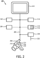
- Fig. 2 shows another embodiment of a user interaction system 200.
- the user interaction system 200 comprises a display 212, an input means 202, a location identification means 204, an overlay image creator 214, a light effect controller 218, an output means 220 and a camera 208.
- the user interaction system 200 further comprises a communication bus 206, which is used by the different components of the system to communicate with each other.
- the display 212 displays a subarea image, an overlay image and/or a camera image.
- the input means 202 receives user input.
- the user input comprises a location indication.
- the location identification means 204 detects which specific location in the environment is indicated by the location indication.
- the overlay image creator 214 generates the overlay image which comprises information with respect to an obtainable lighting effect at the specific location in the environment.
- To create the overlay image a lighting system model 216 is used by the overlay image creator. In the shown embodiment, the lighting system model 216 is stored in the lighting effect controller 218 and is accessed by the overlay image creator
- the user-input means 202 may also receive user input with respect to a desired lighting effect for the specific location which was indicated with the location indication.
- a desired lighting effect a desired effect change may be provided as well, which means that the provided user input is a desired change of the lighting situation which is imaged in the subarea image. If the provided lighting effect change is, for example, "locally higher brightness", the brightness, as imaged in the subarea image, of the specific location has to increase locally.
- the light effect controller 218 uses the desired lighting effect or the desired lighting effect change to generate at least one control signal for at least one light source of the lighting system such that, if the light sources of the lighting system emit light according to the at least one control signal, the desired lighting effect or the desired lighting effect change is optimally obtained at the specific location.
- the light effect controller 218 stores the lighting system model 216, which does not only contain information about which light effects are obtainable by the light sources of the lighting system, but also comprises information which links the obtainable lighting effects with control signals to control the operation of the light sources to obtain the lighting effects.
- the control signal may comprise information with respect to every controllable characteristic of the light sources of the lighting system. For example, if the light emission of the light sources is controllable, the control signal may comprise control information to emit at a specific light intensity. In other examples, the color of the light, the light emission angle or, for example, the position of the light sources is controllable.
- the generated control signal may be provided to the lighting system via the output means 220.
- An output 222 of the output means 220 is for example a DMX-bus, which is a communication bus system which is used by some lighting systems to communicate control parameters to the light sources.
- the output 222 may also employ another communication technology, like a wireless Ethernet, Bluetooth, ZigBee or Z-Wave connection.
- the control signal is not necessarily used for controlling the lighting system.
- the overlay image creator 214 is capable of generating an overlay image which would also present the changed operation of the light sources of the lighting system if the lighting system were controlled with the control signal.
- the overlay image creator 214 accesses the lighting system model 216 to render the lighting effect, which is the result of the control signal.
- Such an overlay image is presented together with the subarea image on the display 212 and the combined view virtually presents the effects of the controlling.
- the overlay image creator 214 is further capable of generating an overlay image which presents information with respect to the feasibility of the desired lighting effect or the desired lighting effect change.
- the overlay image may communicate to the user that not the complete lighting effect may be obtained and the overlay image may possibly communicate to which extent the lighting effect may be obtained.
- the user interaction system 200 further comprises a camera 208.
- the camera obtains a camera image of a part of the environment which comprises the lighting system.
- the display 212 may present the camera image.
- the user interaction system 200 may be used to browse the environment to find a subarea in which the lighting system has to be controlled.
- the user-input means 202 may also receive specific user-input which indicates that at the particular moment of providing the specific user-input the camera image is the subarea image.
- the browsing and the provision of the specific user-input may be used by the user of the user interaction system 200 to record the subarea image.
- the camera image is not anymore presented on the display 212 and the camera image is replaced by the subarea image. In other words, while browsing, the camera image is frozen for controlling the lighting system with respect to one or more locations imaged in the frozen camera image.
- the camera 208 comprises at least one of the subsequent means: means 210 to detect a location of the camera, means 224 to detect a direction in which the camera 208 is directed for recording the camera image, a tilt sensor 226 and means 228 to detect the angle of view of the camera 208.
- the means 210 to detect the location of the camera 208 is, for example, a GPS sensor, or a sensor which is capable of determining the location of the camera 208 with respect to a known fixed point in the environment.
- the means 224 to detect a direction in which the camera 208 is directed is, for example, an electronic compass.
- the means 228 to detect the angle of view is, for example, the zoom controller of the camera 208.
- the different detecting sensors in the camera 208 may be used for different purposes.
- the camera 208 is a fixed camera whose direction and tilt may be controlled. The location of such a camera is known, and the tilt and the direction correspond to the controlled value, and it is assumed that the angle of view is fixed.
- the detected location of the camera 208, the detected recording direction, the detected tilt and/or the detected angle of view are used by the location identification means 204 to determine which specific subarea of the environment is imaged in the subarea image.
- the location identification means 204 has, for example, a model of the environment which is combined with the detected parameters to determine which specific subarea is imaged. Alternatively, trigonometry is used to detect which specific subarea is imaged in the subarea image.
- the detected location of the camera 208, the detected recording direction, the detected tilt and/or the detected angle of view are used by the input means to detect which location indication the user is providing as user-input.
- the fact that the user is directing the camera 208 to a specific point in the environment may be interpreted by the user-input means 202 as the user providing the user-input of the location indication.
- the center point of the camera image may be regarded as the location indication if the user keeps the camera 208 in a fixed position for a predetermined interval of time.
- this may be interpreted by the input means 202 as the user providing the user input of the location indication.
- a mobile phone which is provided with a video camera, comprises the user interaction system of Fig 2 , wherein the camera 208 of the user interaction system is the camera of the mobile phone.
- the user browses through the environment and at a particular moment in time a button is pressed such that the user indicates that the camera image at the particular moment in time is the subarea image.
- the user zooms, with the camera 208, to a specific location of the subarea of the environment and at the moment in time that the maximum zoom is reached, the user-input means 202 considers the location that is imaged in the zoom image as the location indication.
- the user does not have to zoom towards the location which is the location indication, but the user has to align the center of the camera image with the location indication and keep the camera 208 in a fixed position for a predetermined interval of time.
- the location identification means 204 comprises 3D model generation means for generating a model of the subarea through analyzing the subarea image. The determined specific subarea is subsequently used to detect which specific location is indicated with the location indication.
- markers are available in the environment. Some of the markers may be visible in the subarea image and the visible markers are recognized by the location identification means 204 to identify which specific subarea of the environment is imaged in the subarea image.
- the location identification means 204 requires knowledge of available markers and their relation with the environment.
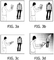
- Fig. 3 shows a typical use case of the user interaction system.
- Fig. 3a shows a mannequin in a shop. The shop is lit by a lighting system. After dressing the mannequin in clothes of the new collection, the shop-assistant gets a portable electronic device having at one side a display and at a side opposite the display a camera. The shop-assistant directs the camera of the portable electronic device towards the mannequin.
- Fig. 3b is shown that the shop-assistant provides input to the portable electronic device and the device records the image of the mannequin as the subarea image.
- Fig. 3c the shop-assistant moves the portable electronic device to a more comfortable position while the display of the portable electronic device still presents the subarea image.
- Fig. 3d shows that the shop-assistant selects on the (touch-) screen of the portable electronic device a location for which he likes to control the lighting.
- the portable electronic device presents, in an overlay image, obtainable effects at the selected location and, subsequently, the shop-assistant provides a desired lighting effect for the selected location.
- the control signals which are generated by the portable electronic device are immediately provided to the lighting system such that the shop-assistant is able to see in the shop what the effect of the controlling is.
- the lighting system of the shop is not immediately controlled and the portable electronic device presents, in the overlay image, the effect of the controlling of the lighting system such that the shop-assistant is able to design the light situation around the mannequin in a virtual environment.
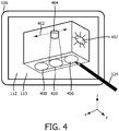
- Fig. 4 relates to another embodiment, wherein the lighting system comprises a redirectable luminaire 404 and a fixed luminaire 407.
- the display 106 is shown, which presents the subarea image 112 and the overlay image 113.
- the overlay image presents the obtainable lighting effects at the location indicated with the stylus 124.
- a relatively bright spot 406 of light may be obtained at the indicated location.
- the light at the indication location is the sum of the light from the redirectable luminaire 404 and the fixed luminaire 407 which emits light towards the whole environment.
- the overlay image 113 also presents the relation between the position of the redirectable luminaire 404 and the lighting effects which may be obtained by the redirectable luminaire 404.
- the redirectable luminaire 404 may be controlled to move along a line 402 shown in the overlay image 113.
- the footprint of the light beam moves along imaged path 410.
- the leftmost footprint 408 is obtained and in the rightmost position the rightmost footprint 406 may be obtained.
- the light effect controller If the user provides as input that the desired effect is that a bright spot has to be created at the indicated location, the light effect controller generates a control signal indicating that the redirectable luminaire 404 has to move to its rightmost position.
- the user may, in an example, drag the brightest spot over the floor to another position.
- the brightest spot substantially corresponds to the footprint of the redirectable luminaire 404.
- the redirectable luminaire 404 is rotatable around an x-axis and a y-axis.
- the direction of the x-axis and the y-axis is indicated at the bottom right end of Fig. 4 .
- the footprint of such a redirectable luminaire may be directed towards the floor or to one of the walls.
- the obtainable effect is that a local bright spot may be created almost anywhere in the subspace.
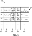
- Fig. 5 shows an example of a lighting system model 500.
- a model may be built using known techniques, such as, for example, so-termed darkroom calibration, light planning software, CAD representations, or using a technology that is related to emitting coded light with the light sources and recording and analyzing the emission of coded light.
- the document that is cited in the background of the art relates to building such a model by using light sources that emit coded light.
- the lighting system model 500 is presented in the form of a Table, however, such a model may be stored differently, for example, in a relational database, and the model may be implemented differently, for example, in a light simulation module.
- the Table comprises in the rows the characteristics of one specific light source. For example, row 512 comprises the parameters of the first light source.
- row 512 comprises the parameters of the first light source.
- an identification code of the respective light source is presented, in column 504 the location (within the environment) of the respective light source, in column 506 the footprint of the respective light source, in column 508 the subspace of the CIE XYZ color space wherein light may be emitted by the respective light source, and in column 510 there is stored the light intensity range of the respective light source.
- the first light source which has the identification code LS1 is located in the environment at a position which is described with coordinates (x1, y1, z1).
- the first light source has an oval footprint on the floor of the environment, and the color of the emitted light is a point somewhere in the middle of the CIE XYZ color space. Further, the first light source may be switched off, so that no light is emitted, but if the light source is switched on, the emitted light intensity is in between a value I min1 and I max1 .
- the overlay image creator finds in column 506 of the table 500 that light sources LS1 and LS2 have a footprint at this specific position and thus that the combination of capabilities of light sources LS1 and LS2 determine the obtainable effects.
- the obtainable light intensities are the sum of the light intensities that may be emitted by light source LS1 and light source LS2.
- the model 500 of Fig. 5 is just an example of such a model. More information may be available in the model, such as for example the relation between value control signals that may be received by the light sources and the characteristics of the light that is emitted in response to receiving the control signals.
- Column 506 may further comprise information with respect to the intensity distribution within the footprint of the light beam of the respective light source when the respective light source emits light at maximum intensity.
- the footprints of the respective light sources are presented in column 506 as a footprint on the floor or the walls of the environment. Light planning software is often also capable of working with virtual planes, and therefore the footprint may also be stored as a footprint on a virtual plane in the environment.
- Column 508 of the model 500 which comprises the color space obtainable by the respective light source, may also be represented by three color points in the XYZ color space which define the corners of the obtainable color space.
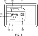
- Fig. 6 shows another embodiment wherein the subarea image 112 is a schematic drawing of a room.
- the subarea image shows, for example, that in an office a meeting table 606 with 6 chairs is placed at the right end of the meeting room.
- a wall 602 has an entrance door and a reproduction of a famous Mondrian painting is attached to a sidewall 610.
- Part 604 of the schematic drawing of the room does not correspond to a wall in the environment and is drawn for clarity reasons only.
- the overlay image 113 presents an obtainable effect 608 on the table 606.
- the obtainable effect 608 is local light on the table 606.
- Fig. 7 shows a flowchart of a method.
- a subarea image is displayed.
- the subarea image is an image of a specific subarea of the environment at the particular moment in time.
- user input is received.
- the user input comprises a location indication.
- it is detected which specific location in the environment is indicated by the location indication.
- an overlay image is generated.
- the overlay image comprises information related to a lighting effect which is obtainable by the lighting system at the specific location.
- the obtainable lighting effect is an effect of at least two controllable light sources of the lighting systems.
- the information related to the obtainable lighting effect is based on a lighting system model representing effects that are obtainable in the environment by controllable light source of the lighting system.
- the subarea image and the overlay image are displayed. In an embodiment, after all the steps of the method have been performed, the method starts again with the step of displaying 702 a subarea image.
- any reference signs placed between parentheses shall not be construed as limiting the claim.
- Use of the verb "comprise” and its conjugations does not exclude the presence of elements or steps other than those stated in a claim.
- the article “a” or “an” preceding an element does not exclude the presence of a plurality of such elements.
- the invention may be implemented by means of hardware comprising several distinct elements, and by means of a suitably programmed computer. In the device claim enumerating several means, several of these means may be embodied by one and the same item of hardware.
Landscapes
- Engineering & Computer Science (AREA)
- Theoretical Computer Science (AREA)
- General Engineering & Computer Science (AREA)
- Physics & Mathematics (AREA)
- General Physics & Mathematics (AREA)
- Human Computer Interaction (AREA)
- Circuit Arrangement For Electric Light Sources In General (AREA)
- Processing Or Creating Images (AREA)
- User Interface Of Digital Computer (AREA)
Priority Applications (1)
| Application Number | Priority Date | Filing Date | Title |
|---|---|---|---|
| EP11776574.3A EP2628363B1 (en) | 2010-10-15 | 2011-10-13 | A method, a user interaction system and a portable electronic devicefor controlling a lighting system |
Applications Claiming Priority (3)
| Application Number | Priority Date | Filing Date | Title |
|---|---|---|---|
| EP10187697 | 2010-10-15 | ||
| PCT/IB2011/054542 WO2012049656A2 (en) | 2010-10-15 | 2011-10-13 | A method and a user interaction system for controlling a lighting system, a portable electronic device and a computer program product |
| EP11776574.3A EP2628363B1 (en) | 2010-10-15 | 2011-10-13 | A method, a user interaction system and a portable electronic devicefor controlling a lighting system |
Publications (2)
| Publication Number | Publication Date |
|---|---|
| EP2628363A2 EP2628363A2 (en) | 2013-08-21 |
| EP2628363B1 true EP2628363B1 (en) | 2021-05-05 |
Family
ID=44898109
Family Applications (1)
| Application Number | Title | Priority Date | Filing Date |
|---|---|---|---|
| EP11776574.3A Active EP2628363B1 (en) | 2010-10-15 | 2011-10-13 | A method, a user interaction system and a portable electronic devicefor controlling a lighting system |
Country Status (7)
Families Citing this family (46)
| Publication number | Priority date | Publication date | Assignee | Title |
|---|---|---|---|---|
| WO2011092609A1 (en) * | 2010-01-29 | 2011-08-04 | Koninklijke Philips Electronics N.V. | Interactive lighting control system and method |
| EP2659739B1 (en) | 2010-12-29 | 2018-05-23 | Philips Lighting Holding B.V. | Setting up hybrid coded-light - zigbee lighting system |
| CN109041372B (zh) | 2011-12-14 | 2021-01-05 | 飞利浦灯具控股公司 | 用于控制照明的方法和装置 |
| US9445480B2 (en) * | 2012-04-12 | 2016-09-13 | Lg Electronics Inc. | Lighting system, lighting apparatus, and lighting control method |
| US9089227B2 (en) * | 2012-05-01 | 2015-07-28 | Hussmann Corporation | Portable device and method for product lighting control, product display lighting method and system, method for controlling product lighting, and -method for setting product display location lighting |
| CN104541580B (zh) * | 2012-08-16 | 2018-03-02 | 飞利浦灯具控股公司 | 控制包括一个或多个可控设备的系统 |
| US10678407B2 (en) | 2012-08-16 | 2020-06-09 | Signify Holding B.V. | Controlling a system comprising one or more controllable device |
| JP2014044916A (ja) * | 2012-08-28 | 2014-03-13 | Panasonic Corp | 照明制御システム |
| EP2891386B1 (en) * | 2012-08-30 | 2016-03-16 | Koninklijke Philips N.V. | Controlling light source(s) via a portable device |
| JP6097963B2 (ja) * | 2012-09-13 | 2017-03-22 | パナソニックIpマネジメント株式会社 | 照明システム |
| ES2796739T3 (es) * | 2012-10-24 | 2020-11-30 | Signify Holding Bv | Generación de un diseño de dispositivo de iluminación |
| CN104756604B (zh) * | 2012-10-24 | 2019-07-09 | 飞利浦灯具控股公司 | 帮助用户选择照明设备设计 |
| PL2939504T5 (pl) * | 2012-10-24 | 2022-10-24 | Signify Holding B.V. | Pomaganie użytkownikowi w wyborze projektu urządzenia oświetleniowego |
| WO2014064634A1 (en) * | 2012-10-24 | 2014-05-01 | Koninklijke Philips N.V. | Assisting a user in selecting a lighting device design |
| JP6495294B2 (ja) * | 2013-09-16 | 2019-04-03 | シグニファイ ホールディング ビー ヴィ | 照明を制御する方法及び装置 |
| US10568179B2 (en) * | 2013-09-20 | 2020-02-18 | Osram Sylvania Inc. | Techniques and photographical user interface for controlling solid-state luminaire with electronically adjustable light beam distribution |
| US9872368B2 (en) * | 2014-01-10 | 2018-01-16 | Panasonic Intellectual Property Corporation Of America | Control method for mobile device |
| CN105050227B (zh) * | 2014-03-21 | 2019-07-26 | 奥斯兰姆施尔凡尼亚公司 | 用于控制可调整光束分布的固态泛光灯的方法和用户接口 |
| WO2015169619A1 (en) | 2014-05-05 | 2015-11-12 | Koninklijke Philips N.V. | Device with a camera and a screen |
| US10134064B2 (en) * | 2014-06-27 | 2018-11-20 | Ledvance Llc | Lighting audit and LED lamp retrofit |
| CN104093251B (zh) * | 2014-07-08 | 2017-12-05 | 四川长虹电器股份有限公司 | 基于智能灯泡的景观灯应用方法 |
| WO2016009016A1 (en) | 2014-07-17 | 2016-01-21 | Koninklijke Philips N.V. | Method of obtaining gesture zone definition data for a control system based on user input |
| CN104219833B (zh) * | 2014-07-31 | 2017-12-05 | 四川长虹电器股份有限公司 | 智能生成灯光位置分布电子地图的方法 |
| EP3180963B8 (en) | 2014-08-11 | 2019-04-10 | Signify Holding B.V. | Light system interface and method |
| RU2707183C2 (ru) * | 2014-09-01 | 2019-11-25 | Филипс Лайтинг Холдинг Б.В. | Способ управления осветительной системой, компьютерный программный продукт, носимое вычислительное устройство и набор осветительной системы |
| DE102014225706A1 (de) * | 2014-12-12 | 2016-06-16 | Fraunhofer-Gesellschaft zur Förderung der angewandten Forschung e.V. | Verfahren zur selektiven Einstellung einer gewünschten Helligkeit und/oder Farbe eines bestimmten Raumbereiches und Datenverarbeitungsvorrichtung hierzu |
| JP6704935B2 (ja) * | 2015-04-22 | 2020-06-03 | シグニファイ ホールディング ビー ヴィSignify Holding B.V. | 照明配置図作成器 |
| US10292246B2 (en) * | 2015-04-28 | 2019-05-14 | Signify Holding B.V. | Area illumination system and method |
| US20160370981A1 (en) * | 2015-06-19 | 2016-12-22 | Uniform Industrial Corp. | Editing device and method for edit and preview of light control pattern |
| CN106406504B (zh) * | 2015-07-27 | 2019-05-07 | 常州市武进区半导体照明应用技术研究院 | 人机交互界面的氛围渲染系统与方法 |
| WO2018200685A2 (en) | 2017-04-27 | 2018-11-01 | Ecosense Lighting Inc. | Methods and systems for an automated design, fulfillment, deployment and operation platform for lighting installations |
| JP2020504895A (ja) * | 2016-10-27 | 2020-02-13 | シグニファイ ホールディング ビー ヴィSignify Holding B.V. | 物体識別子を記憶する方法 |
| WO2018082929A1 (en) * | 2016-11-01 | 2018-05-11 | Philips Lighting Holding B.V. | A lighting-system and a lighting-system control method |
| GB2559321B (en) * | 2017-01-10 | 2022-09-21 | Hoare Lea Llp | Graphical lighting control system |
| US10412802B2 (en) * | 2017-03-02 | 2019-09-10 | Osram Sylvania Inc. | Luminaire with programmable light distribution |
| US10420186B2 (en) * | 2017-05-31 | 2019-09-17 | Nbcuniversal Media, Llc | Color tunable light with zone control |
| JP7163361B2 (ja) | 2017-07-26 | 2022-10-31 | シグニファイ ホールディング ビー ヴィ | 光源を介してデバイスの存在を伝えるためのシステム |
| US10098204B1 (en) | 2018-03-13 | 2018-10-09 | Cisco Technology, Inc. | System to determine the placement of smart light emitters |
| US11151797B2 (en) | 2018-04-09 | 2021-10-19 | Signify Holding B.V. | Superimposing a virtual representation of a sensor and its detection zone over an image |
| ES2992891T3 (en) | 2018-04-13 | 2024-12-19 | Nbcuniversal Media Llc | Digitally adjustable focused beam lighting system |
| DE102019133753A1 (de) * | 2018-12-10 | 2020-07-16 | Electronic Theatre Controls, Inc. | Werkzeuge für augmentierte realität in der lichtgestaltung |
| DE102019102252A1 (de) * | 2019-01-30 | 2020-07-30 | Trilux Gmbh & Co. Kg | Verfahren zur Unterstützung der Installation eines Sensors bzw. einer Leuchte in Beleuchtungssystemen |
| US11047560B2 (en) * | 2019-05-29 | 2021-06-29 | Nbcuniversal Media, Llc | Light emitting diode cooling systems and methods |
| US11333342B2 (en) | 2019-05-29 | 2022-05-17 | Nbcuniversal Media, Llc | Light emitting diode cooling systems and methods |
| US20240219888A1 (en) * | 2022-12-29 | 2024-07-04 | Integrated Illumination Systems, Inc. | Systems and methods for manufacturing light fixtures |
| US12025302B1 (en) | 2023-04-28 | 2024-07-02 | NBCUniversal Studios LLC | Light emitting diode lighting systems and methods |
Family Cites Families (14)
| Publication number | Priority date | Publication date | Assignee | Title |
|---|---|---|---|---|
| KR100538948B1 (ko) * | 2003-08-11 | 2005-12-27 | 삼성전자주식회사 | 적응적 이미지의 표시가 가능한 휴대용 단말기의디스플레이 장치 |
| WO2006023149A2 (en) * | 2004-07-08 | 2006-03-02 | Color Kinetics Incorporated | Led package methods and systems |
| EP1875778A2 (en) | 2005-03-23 | 2008-01-09 | Koninklijke Philips Electronics N.V. | Light condition recorder system and method |
| WO2007072294A1 (en) * | 2005-12-22 | 2007-06-28 | Koninklijke Philips Electronics N.V. | Button arrangement for colored lighting controller |
| KR20090091825A (ko) * | 2006-12-22 | 2009-08-28 | 코닌클리즈케 필립스 일렉트로닉스 엔.브이. | 추상적인 기술로부터 조명 분위기를 렌더링하는 것의 가능성을 자동적으로 검증하기 위한 방법 및 시스템 |
| CN105517255B (zh) | 2007-05-22 | 2018-05-15 | 飞利浦灯具控股公司 | 远程照明控制 |
| CN101690406A (zh) | 2007-06-29 | 2010-03-31 | 皇家飞利浦电子股份有限公司 | 具有用于交互地改变照明系统内设置的用户界面的光控制系统以及使用用户界面交互地改变照明系统内设置的方法 |
| JP2009016941A (ja) * | 2007-06-29 | 2009-01-22 | Funai Electric Co Ltd | 撮像装置 |
| WO2009004586A1 (en) | 2007-07-05 | 2009-01-08 | Philips Intellectual Property & Standards Gmbh | Apparatus and method for modifying a light scene |
| US8494660B2 (en) * | 2008-07-11 | 2013-07-23 | Koninklijke Philips N.V. | Method and computer implemented apparatus for controlling a lighting infrastructure |
| CN102165849B (zh) | 2008-09-26 | 2016-08-03 | 皇家飞利浦电子股份有限公司 | 用于多个光源的自动调试的系统和方法 |
| PL3484249T3 (pl) * | 2009-01-06 | 2022-05-23 | Signify Holding B.V. | Układ sterowania do sterowania jednym lub większą liczbą źródeł urządzeń sterowalnych i sposób umożliwiania takiego sterowania |
| CN102652463B (zh) * | 2009-12-18 | 2014-10-29 | 皇家飞利浦电子股份有限公司 | 用于创建光场景的照明工具 |
| WO2011092609A1 (en) | 2010-01-29 | 2011-08-04 | Koninklijke Philips Electronics N.V. | Interactive lighting control system and method |
-
2011
- 2011-10-13 BR BR112013008713-7A patent/BR112013008713A2/pt not_active IP Right Cessation
- 2011-10-13 US US13/879,057 patent/US9041731B2/en active Active
- 2011-10-13 CN CN201180049717.XA patent/CN103168505B/zh active Active
- 2011-10-13 EP EP11776574.3A patent/EP2628363B1/en active Active
- 2011-10-13 WO PCT/IB2011/054542 patent/WO2012049656A2/en active Application Filing
- 2011-10-13 CA CA2821303A patent/CA2821303C/en active Active
- 2011-10-13 JP JP2013533318A patent/JP5819431B2/ja active Active
Also Published As
| Publication number | Publication date |
|---|---|
| CA2821303A1 (en) | 2012-04-19 |
| JP2014500573A (ja) | 2014-01-09 |
| JP5819431B2 (ja) | 2015-11-24 |
| US9041731B2 (en) | 2015-05-26 |
| US20130214698A1 (en) | 2013-08-22 |
| CA2821303C (en) | 2018-01-16 |
| CN103168505A (zh) | 2013-06-19 |
| RU2013122115A (ru) | 2014-11-20 |
| WO2012049656A3 (en) | 2012-09-13 |
| EP2628363A2 (en) | 2013-08-21 |
| BR112013008713A2 (pt) | 2021-05-25 |
| CN103168505B (zh) | 2015-11-25 |
| WO2012049656A2 (en) | 2012-04-19 |
Similar Documents
| Publication | Publication Date | Title |
|---|---|---|
| EP2628363B1 (en) | A method, a user interaction system and a portable electronic devicefor controlling a lighting system | |
| RU2622405C2 (ru) | Дистанционное управление источником света | |
| EP2298034B1 (en) | Method and computer implemented apparatus for controlling a lighting infrastructure | |
| US10353535B2 (en) | Multi-view display viewing zone layout and content assignment | |
| US10049493B1 (en) | System and methods for providing interaction with elements in a virtual architectural visualization | |
| JP5825561B2 (ja) | インタラクティブな照明制御システム及び方法 | |
| JP6445025B2 (ja) | ジェスチャ制御 | |
| KR20170105445A (ko) | 디바이스 관리를 포함하는 디스플레이 장치들의 구성 및 동작 | |
| EP3289829B1 (en) | Color picker | |
| KR20210083574A (ko) | 가상 공간 인테리어를 이용한 인터페이스 제공 방법 및 그 장치 | |
| US11410390B2 (en) | Augmented reality device for visualizing luminaire fixtures | |
| JP2017520886A (ja) | 照明システム | |
| US10803630B2 (en) | Image processing system, method, and program | |
| WO2010070517A1 (en) | System for simulation of a lighting distribution | |
| WO2020244577A1 (zh) | 一种基于位置的交互方法和交互系统 | |
| RU2574586C2 (ru) | Способ и система взаимодействия с пользователем для управления системой освещения, портативное электронное устройство и компьютерный программный продукт | |
| WO2021224262A2 (en) | Augmented reality based design | |
| KR102595377B1 (ko) | 사물 인터넷 환경에서 조명을 관리하는 방법 및 장치 |
Legal Events
| Date | Code | Title | Description |
|---|---|---|---|
| PUAI | Public reference made under article 153(3) epc to a published international application that has entered the european phase |
Free format text: ORIGINAL CODE: 0009012 |
|
| 17P | Request for examination filed |
Effective date: 20130515 |
|
| AK | Designated contracting states |
Kind code of ref document: A2 Designated state(s): AL AT BE BG CH CY CZ DE DK EE ES FI FR GB GR HR HU IE IS IT LI LT LU LV MC MK MT NL NO PL PT RO RS SE SI SK SM TR |
|
| RAP1 | Party data changed (applicant data changed or rights of an application transferred) |
Owner name: KONINKLIJKE PHILIPS N.V. |
|
| DAX | Request for extension of the european patent (deleted) | ||
| RAP1 | Party data changed (applicant data changed or rights of an application transferred) |
Owner name: PHILIPS LIGHTING HOLDING B.V. |
|
| RIN1 | Information on inventor provided before grant (corrected) |
Inventor name: VAN DE SLUIS, BARTEL, MARINUS Inventor name: ENGELEN, DIRK, VALENTINUS, RENE Inventor name: MASON, JONATHAN, DAVID Inventor name: WEDA, JOHANNES Inventor name: ALIAKSEYEU, DZMITRY, VIKTOROVICH |
|
| RAP1 | Party data changed (applicant data changed or rights of an application transferred) |
Owner name: PHILIPS LIGHTING HOLDING B.V. |
|
| RAP1 | Party data changed (applicant data changed or rights of an application transferred) |
Owner name: SIGNIFY HOLDING B.V. |
|
| STAA | Information on the status of an ep patent application or granted ep patent |
Free format text: STATUS: EXAMINATION IS IN PROGRESS |
|
| 17Q | First examination report despatched |
Effective date: 20190604 |
|
| REG | Reference to a national code |
Ref country code: DE Ref legal event code: R079 Ref document number: 602011070882 Country of ref document: DE Free format text: PREVIOUS MAIN CLASS: H05B0037020000 Ipc: H05B0047155000 |
|
| GRAP | Despatch of communication of intention to grant a patent |
Free format text: ORIGINAL CODE: EPIDOSNIGR1 |
|
| STAA | Information on the status of an ep patent application or granted ep patent |
Free format text: STATUS: GRANT OF PATENT IS INTENDED |
|
| RIC1 | Information provided on ipc code assigned before grant |
Ipc: G06F 3/01 20060101ALI20201116BHEP Ipc: G06T 11/60 20060101ALI20201116BHEP Ipc: G06F 3/03 20060101ALI20201116BHEP Ipc: H05B 47/19 20200101ALI20201116BHEP Ipc: H05B 47/155 20200101AFI20201116BHEP |
|
| INTG | Intention to grant announced |
Effective date: 20201130 |
|
| GRAS | Grant fee paid |
Free format text: ORIGINAL CODE: EPIDOSNIGR3 |
|
| GRAA | (expected) grant |
Free format text: ORIGINAL CODE: 0009210 |
|
| STAA | Information on the status of an ep patent application or granted ep patent |
Free format text: STATUS: THE PATENT HAS BEEN GRANTED |
|
| AK | Designated contracting states |
Kind code of ref document: B1 Designated state(s): AL AT BE BG CH CY CZ DE DK EE ES FI FR GB GR HR HU IE IS IT LI LT LU LV MC MK MT NL NO PL PT RO RS SE SI SK SM TR |
|
| REG | Reference to a national code |
Ref country code: GB Ref legal event code: FG4D |
|
| REG | Reference to a national code |
Ref country code: CH Ref legal event code: EP |
|
| REG | Reference to a national code |
Ref country code: AT Ref legal event code: REF Ref document number: 1391512 Country of ref document: AT Kind code of ref document: T Effective date: 20210515 |
|
| REG | Reference to a national code |
Ref country code: DE Ref legal event code: R096 Ref document number: 602011070882 Country of ref document: DE |
|
| REG | Reference to a national code |
Ref country code: IE Ref legal event code: FG4D |
|
| REG | Reference to a national code |
Ref country code: SE Ref legal event code: TRGR |
|
| REG | Reference to a national code |
Ref country code: LT Ref legal event code: MG9D |
|
| REG | Reference to a national code |
Ref country code: AT Ref legal event code: MK05 Ref document number: 1391512 Country of ref document: AT Kind code of ref document: T Effective date: 20210505 |
|
| PG25 | Lapsed in a contracting state [announced via postgrant information from national office to epo] |
Ref country code: LT Free format text: LAPSE BECAUSE OF FAILURE TO SUBMIT A TRANSLATION OF THE DESCRIPTION OR TO PAY THE FEE WITHIN THE PRESCRIBED TIME-LIMIT Effective date: 20210505 Ref country code: FI Free format text: LAPSE BECAUSE OF FAILURE TO SUBMIT A TRANSLATION OF THE DESCRIPTION OR TO PAY THE FEE WITHIN THE PRESCRIBED TIME-LIMIT Effective date: 20210505 Ref country code: BG Free format text: LAPSE BECAUSE OF FAILURE TO SUBMIT A TRANSLATION OF THE DESCRIPTION OR TO PAY THE FEE WITHIN THE PRESCRIBED TIME-LIMIT Effective date: 20210805 Ref country code: AT Free format text: LAPSE BECAUSE OF FAILURE TO SUBMIT A TRANSLATION OF THE DESCRIPTION OR TO PAY THE FEE WITHIN THE PRESCRIBED TIME-LIMIT Effective date: 20210505 Ref country code: HR Free format text: LAPSE BECAUSE OF FAILURE TO SUBMIT A TRANSLATION OF THE DESCRIPTION OR TO PAY THE FEE WITHIN THE PRESCRIBED TIME-LIMIT Effective date: 20210505 |
|
| PG25 | Lapsed in a contracting state [announced via postgrant information from national office to epo] |
Ref country code: LV Free format text: LAPSE BECAUSE OF FAILURE TO SUBMIT A TRANSLATION OF THE DESCRIPTION OR TO PAY THE FEE WITHIN THE PRESCRIBED TIME-LIMIT Effective date: 20210505 Ref country code: GR Free format text: LAPSE BECAUSE OF FAILURE TO SUBMIT A TRANSLATION OF THE DESCRIPTION OR TO PAY THE FEE WITHIN THE PRESCRIBED TIME-LIMIT Effective date: 20210806 Ref country code: IS Free format text: LAPSE BECAUSE OF FAILURE TO SUBMIT A TRANSLATION OF THE DESCRIPTION OR TO PAY THE FEE WITHIN THE PRESCRIBED TIME-LIMIT Effective date: 20210905 Ref country code: RS Free format text: LAPSE BECAUSE OF FAILURE TO SUBMIT A TRANSLATION OF THE DESCRIPTION OR TO PAY THE FEE WITHIN THE PRESCRIBED TIME-LIMIT Effective date: 20210505 Ref country code: ES Free format text: LAPSE BECAUSE OF FAILURE TO SUBMIT A TRANSLATION OF THE DESCRIPTION OR TO PAY THE FEE WITHIN THE PRESCRIBED TIME-LIMIT Effective date: 20210505 Ref country code: PT Free format text: LAPSE BECAUSE OF FAILURE TO SUBMIT A TRANSLATION OF THE DESCRIPTION OR TO PAY THE FEE WITHIN THE PRESCRIBED TIME-LIMIT Effective date: 20210906 Ref country code: NO Free format text: LAPSE BECAUSE OF FAILURE TO SUBMIT A TRANSLATION OF THE DESCRIPTION OR TO PAY THE FEE WITHIN THE PRESCRIBED TIME-LIMIT Effective date: 20210805 Ref country code: PL Free format text: LAPSE BECAUSE OF FAILURE TO SUBMIT A TRANSLATION OF THE DESCRIPTION OR TO PAY THE FEE WITHIN THE PRESCRIBED TIME-LIMIT Effective date: 20210505 |
|
| REG | Reference to a national code |
Ref country code: NL Ref legal event code: MP Effective date: 20210505 |
|
| PG25 | Lapsed in a contracting state [announced via postgrant information from national office to epo] |
Ref country code: NL Free format text: LAPSE BECAUSE OF FAILURE TO SUBMIT A TRANSLATION OF THE DESCRIPTION OR TO PAY THE FEE WITHIN THE PRESCRIBED TIME-LIMIT Effective date: 20210505 |
|
| PG25 | Lapsed in a contracting state [announced via postgrant information from national office to epo] |
Ref country code: RO Free format text: LAPSE BECAUSE OF FAILURE TO SUBMIT A TRANSLATION OF THE DESCRIPTION OR TO PAY THE FEE WITHIN THE PRESCRIBED TIME-LIMIT Effective date: 20210505 Ref country code: DK Free format text: LAPSE BECAUSE OF FAILURE TO SUBMIT A TRANSLATION OF THE DESCRIPTION OR TO PAY THE FEE WITHIN THE PRESCRIBED TIME-LIMIT Effective date: 20210505 Ref country code: EE Free format text: LAPSE BECAUSE OF FAILURE TO SUBMIT A TRANSLATION OF THE DESCRIPTION OR TO PAY THE FEE WITHIN THE PRESCRIBED TIME-LIMIT Effective date: 20210505 Ref country code: CZ Free format text: LAPSE BECAUSE OF FAILURE TO SUBMIT A TRANSLATION OF THE DESCRIPTION OR TO PAY THE FEE WITHIN THE PRESCRIBED TIME-LIMIT Effective date: 20210505 Ref country code: SK Free format text: LAPSE BECAUSE OF FAILURE TO SUBMIT A TRANSLATION OF THE DESCRIPTION OR TO PAY THE FEE WITHIN THE PRESCRIBED TIME-LIMIT Effective date: 20210505 Ref country code: SM Free format text: LAPSE BECAUSE OF FAILURE TO SUBMIT A TRANSLATION OF THE DESCRIPTION OR TO PAY THE FEE WITHIN THE PRESCRIBED TIME-LIMIT Effective date: 20210505 |
|
| REG | Reference to a national code |
Ref country code: DE Ref legal event code: R097 Ref document number: 602011070882 Country of ref document: DE |
|
| PLBE | No opposition filed within time limit |
Free format text: ORIGINAL CODE: 0009261 |
|
| STAA | Information on the status of an ep patent application or granted ep patent |
Free format text: STATUS: NO OPPOSITION FILED WITHIN TIME LIMIT |
|
| 26N | No opposition filed |
Effective date: 20220208 |
|
| PG25 | Lapsed in a contracting state [announced via postgrant information from national office to epo] |
Ref country code: IS Free format text: LAPSE BECAUSE OF FAILURE TO SUBMIT A TRANSLATION OF THE DESCRIPTION OR TO PAY THE FEE WITHIN THE PRESCRIBED TIME-LIMIT Effective date: 20210905 Ref country code: AL Free format text: LAPSE BECAUSE OF FAILURE TO SUBMIT A TRANSLATION OF THE DESCRIPTION OR TO PAY THE FEE WITHIN THE PRESCRIBED TIME-LIMIT Effective date: 20210505 |
|
| REG | Reference to a national code |
Ref country code: CH Ref legal event code: PL |
|
| REG | Reference to a national code |
Ref country code: BE Ref legal event code: MM Effective date: 20211031 |
|
| PG25 | Lapsed in a contracting state [announced via postgrant information from national office to epo] |
Ref country code: MC Free format text: LAPSE BECAUSE OF FAILURE TO SUBMIT A TRANSLATION OF THE DESCRIPTION OR TO PAY THE FEE WITHIN THE PRESCRIBED TIME-LIMIT Effective date: 20210505 |
|
| PG25 | Lapsed in a contracting state [announced via postgrant information from national office to epo] |
Ref country code: LU Free format text: LAPSE BECAUSE OF NON-PAYMENT OF DUE FEES Effective date: 20211013 Ref country code: IT Free format text: LAPSE BECAUSE OF FAILURE TO SUBMIT A TRANSLATION OF THE DESCRIPTION OR TO PAY THE FEE WITHIN THE PRESCRIBED TIME-LIMIT Effective date: 20210505 Ref country code: BE Free format text: LAPSE BECAUSE OF NON-PAYMENT OF DUE FEES Effective date: 20211031 |
|
| PG25 | Lapsed in a contracting state [announced via postgrant information from national office to epo] |
Ref country code: LI Free format text: LAPSE BECAUSE OF NON-PAYMENT OF DUE FEES Effective date: 20211031 Ref country code: CH Free format text: LAPSE BECAUSE OF NON-PAYMENT OF DUE FEES Effective date: 20211031 |
|
| PG25 | Lapsed in a contracting state [announced via postgrant information from national office to epo] |
Ref country code: IE Free format text: LAPSE BECAUSE OF NON-PAYMENT OF DUE FEES Effective date: 20211013 |
|
| PG25 | Lapsed in a contracting state [announced via postgrant information from national office to epo] |
Ref country code: HU Free format text: LAPSE BECAUSE OF FAILURE TO SUBMIT A TRANSLATION OF THE DESCRIPTION OR TO PAY THE FEE WITHIN THE PRESCRIBED TIME-LIMIT; INVALID AB INITIO Effective date: 20111013 Ref country code: CY Free format text: LAPSE BECAUSE OF FAILURE TO SUBMIT A TRANSLATION OF THE DESCRIPTION OR TO PAY THE FEE WITHIN THE PRESCRIBED TIME-LIMIT Effective date: 20210505 |
|
| P01 | Opt-out of the competence of the unified patent court (upc) registered |
Effective date: 20230421 |
|
| PG25 | Lapsed in a contracting state [announced via postgrant information from national office to epo] |
Ref country code: MK Free format text: LAPSE BECAUSE OF FAILURE TO SUBMIT A TRANSLATION OF THE DESCRIPTION OR TO PAY THE FEE WITHIN THE PRESCRIBED TIME-LIMIT Effective date: 20210505 |
|
| PG25 | Lapsed in a contracting state [announced via postgrant information from national office to epo] |
Ref country code: TR Free format text: LAPSE BECAUSE OF FAILURE TO SUBMIT A TRANSLATION OF THE DESCRIPTION OR TO PAY THE FEE WITHIN THE PRESCRIBED TIME-LIMIT Effective date: 20210505 |
|
| PG25 | Lapsed in a contracting state [announced via postgrant information from national office to epo] |
Ref country code: MT Free format text: LAPSE BECAUSE OF FAILURE TO SUBMIT A TRANSLATION OF THE DESCRIPTION OR TO PAY THE FEE WITHIN THE PRESCRIBED TIME-LIMIT Effective date: 20210505 |
|
| PGFP | Annual fee paid to national office [announced via postgrant information from national office to epo] |
Ref country code: GB Payment date: 20241022 Year of fee payment: 14 |
|
| PGFP | Annual fee paid to national office [announced via postgrant information from national office to epo] |
Ref country code: FR Payment date: 20241025 Year of fee payment: 14 |
|
| PGFP | Annual fee paid to national office [announced via postgrant information from national office to epo] |
Ref country code: SE Payment date: 20241025 Year of fee payment: 14 |
|
| PGFP | Annual fee paid to national office [announced via postgrant information from national office to epo] |
Ref country code: DE Payment date: 20241227 Year of fee payment: 14 |