EP2626476B2 - Working machine with settings change system - Google Patents
Working machine with settings change system Download PDFInfo
- Publication number
- EP2626476B2 EP2626476B2 EP12817066.9A EP12817066A EP2626476B2 EP 2626476 B2 EP2626476 B2 EP 2626476B2 EP 12817066 A EP12817066 A EP 12817066A EP 2626476 B2 EP2626476 B2 EP 2626476B2
- Authority
- EP
- European Patent Office
- Prior art keywords
- mobile terminal
- setting
- code
- working machine
- control device
- Prior art date
- Legal status (The legal status is an assumption and is not a legal conclusion. Google has not performed a legal analysis and makes no representation as to the accuracy of the status listed.)
- Active
Links
- 230000008859 change Effects 0.000 title claims description 130
- 238000004891 communication Methods 0.000 claims description 112
- 238000003860 storage Methods 0.000 claims description 66
- 230000004044 response Effects 0.000 claims description 8
- 238000007726 management method Methods 0.000 description 52
- 238000004519 manufacturing process Methods 0.000 description 21
- 230000005540 biological transmission Effects 0.000 description 20
- 238000010586 diagram Methods 0.000 description 19
- 238000000034 method Methods 0.000 description 13
- 238000013500 data storage Methods 0.000 description 11
- 230000007246 mechanism Effects 0.000 description 11
- 238000012545 processing Methods 0.000 description 11
- 238000009826 distribution Methods 0.000 description 9
- 239000000446 fuel Substances 0.000 description 9
- 238000002347 injection Methods 0.000 description 8
- 239000007924 injection Substances 0.000 description 8
- 239000004973 liquid crystal related substance Substances 0.000 description 8
- 238000010276 construction Methods 0.000 description 7
- 230000007704 transition Effects 0.000 description 6
- 238000003825 pressing Methods 0.000 description 5
- 230000008602 contraction Effects 0.000 description 4
- 230000006870 function Effects 0.000 description 3
- 230000015654 memory Effects 0.000 description 3
- 230000007935 neutral effect Effects 0.000 description 3
- 238000012508 change request Methods 0.000 description 2
- 230000007423 decrease Effects 0.000 description 2
- 230000003247 decreasing effect Effects 0.000 description 2
- XLYOFNOQVPJJNP-UHFFFAOYSA-N water Substances O XLYOFNOQVPJJNP-UHFFFAOYSA-N 0.000 description 2
- 241000206607 Porphyra umbilicalis Species 0.000 description 1
- 230000001133 acceleration Effects 0.000 description 1
- 230000008033 biological extinction Effects 0.000 description 1
- 230000001419 dependent effect Effects 0.000 description 1
- 238000013461 design Methods 0.000 description 1
- 238000001514 detection method Methods 0.000 description 1
- 238000011161 development Methods 0.000 description 1
- 230000000694 effects Effects 0.000 description 1
- 239000000284 extract Substances 0.000 description 1
- 239000002828 fuel tank Substances 0.000 description 1
- 238000012986 modification Methods 0.000 description 1
- 230000004048 modification Effects 0.000 description 1
- 230000002265 prevention Effects 0.000 description 1
- 239000000243 solution Substances 0.000 description 1
Images


Classifications
-
- A—HUMAN NECESSITIES
- A01—AGRICULTURE; FORESTRY; ANIMAL HUSBANDRY; HUNTING; TRAPPING; FISHING
- A01B—SOIL WORKING IN AGRICULTURE OR FORESTRY; PARTS, DETAILS, OR ACCESSORIES OF AGRICULTURAL MACHINES OR IMPLEMENTS, IN GENERAL
- A01B79/00—Methods for working soil
- A01B79/005—Precision agriculture
-
- E—FIXED CONSTRUCTIONS
- E02—HYDRAULIC ENGINEERING; FOUNDATIONS; SOIL SHIFTING
- E02F—DREDGING; SOIL-SHIFTING
- E02F9/00—Component parts of dredgers or soil-shifting machines, not restricted to one of the kinds covered by groups E02F3/00 - E02F7/00
- E02F9/20—Drives; Control devices
-
- A—HUMAN NECESSITIES
- A01—AGRICULTURE; FORESTRY; ANIMAL HUSBANDRY; HUNTING; TRAPPING; FISHING
- A01B—SOIL WORKING IN AGRICULTURE OR FORESTRY; PARTS, DETAILS, OR ACCESSORIES OF AGRICULTURAL MACHINES OR IMPLEMENTS, IN GENERAL
- A01B76/00—Parts, details or accessories of agricultural machines or implements, not provided for in groups A01B51/00 - A01B75/00
-
- A—HUMAN NECESSITIES
- A01—AGRICULTURE; FORESTRY; ANIMAL HUSBANDRY; HUNTING; TRAPPING; FISHING
- A01B—SOIL WORKING IN AGRICULTURE OR FORESTRY; PARTS, DETAILS, OR ACCESSORIES OF AGRICULTURAL MACHINES OR IMPLEMENTS, IN GENERAL
- A01B77/00—Machines for lifting and treating soil
-
- B—PERFORMING OPERATIONS; TRANSPORTING
- B60—VEHICLES IN GENERAL
- B60K—ARRANGEMENT OR MOUNTING OF PROPULSION UNITS OR OF TRANSMISSIONS IN VEHICLES; ARRANGEMENT OR MOUNTING OF PLURAL DIVERSE PRIME-MOVERS IN VEHICLES; AUXILIARY DRIVES FOR VEHICLES; INSTRUMENTATION OR DASHBOARDS FOR VEHICLES; ARRANGEMENTS IN CONNECTION WITH COOLING, AIR INTAKE, GAS EXHAUST OR FUEL SUPPLY OF PROPULSION UNITS IN VEHICLES
- B60K35/00—Arrangement of adaptations of instruments
-
- B60K35/80—
-
- B—PERFORMING OPERATIONS; TRANSPORTING
- B60—VEHICLES IN GENERAL
- B60R—VEHICLES, VEHICLE FITTINGS, OR VEHICLE PARTS, NOT OTHERWISE PROVIDED FOR
- B60R16/00—Electric or fluid circuits specially adapted for vehicles and not otherwise provided for; Arrangement of elements of electric or fluid circuits specially adapted for vehicles and not otherwise provided for
- B60R16/02—Electric or fluid circuits specially adapted for vehicles and not otherwise provided for; Arrangement of elements of electric or fluid circuits specially adapted for vehicles and not otherwise provided for electric constitutive elements
-
- B—PERFORMING OPERATIONS; TRANSPORTING
- B66—HOISTING; LIFTING; HAULING
- B66C—CRANES; LOAD-ENGAGING ELEMENTS OR DEVICES FOR CRANES, CAPSTANS, WINCHES, OR TACKLES
- B66C1/00—Load-engaging elements or devices attached to lifting or lowering gear of cranes or adapted for connection therewith for transmitting lifting forces to articles or groups of articles
- B66C1/02—Load-engaging elements or devices attached to lifting or lowering gear of cranes or adapted for connection therewith for transmitting lifting forces to articles or groups of articles by suction means
- B66C1/0256—Operating and control devices
-
- B—PERFORMING OPERATIONS; TRANSPORTING
- B66—HOISTING; LIFTING; HAULING
- B66C—CRANES; LOAD-ENGAGING ELEMENTS OR DEVICES FOR CRANES, CAPSTANS, WINCHES, OR TACKLES
- B66C17/00—Overhead travelling cranes comprising one or more substantially horizontal girders the ends of which are directly supported by wheels or rollers running on tracks carried by spaced supports
- B66C17/06—Overhead travelling cranes comprising one or more substantially horizontal girders the ends of which are directly supported by wheels or rollers running on tracks carried by spaced supports specially adapted for particular purposes, e.g. in foundries, forges; combined with auxiliary apparatus serving particular purposes
- B66C17/18—Overhead travelling cranes comprising one or more substantially horizontal girders the ends of which are directly supported by wheels or rollers running on tracks carried by spaced supports specially adapted for particular purposes, e.g. in foundries, forges; combined with auxiliary apparatus serving particular purposes for manipulating workpieces during forging operations
-
- E—FIXED CONSTRUCTIONS
- E02—HYDRAULIC ENGINEERING; FOUNDATIONS; SOIL SHIFTING
- E02F—DREDGING; SOIL-SHIFTING
- E02F9/00—Component parts of dredgers or soil-shifting machines, not restricted to one of the kinds covered by groups E02F3/00 - E02F7/00
- E02F9/20—Drives; Control devices
- E02F9/2025—Particular purposes of control systems not otherwise provided for
- E02F9/2054—Fleet management
-
- E—FIXED CONSTRUCTIONS
- E02—HYDRAULIC ENGINEERING; FOUNDATIONS; SOIL SHIFTING
- E02F—DREDGING; SOIL-SHIFTING
- E02F9/00—Component parts of dredgers or soil-shifting machines, not restricted to one of the kinds covered by groups E02F3/00 - E02F7/00
- E02F9/24—Safety devices, e.g. for preventing overload
-
- E—FIXED CONSTRUCTIONS
- E02—HYDRAULIC ENGINEERING; FOUNDATIONS; SOIL SHIFTING
- E02F—DREDGING; SOIL-SHIFTING
- E02F9/00—Component parts of dredgers or soil-shifting machines, not restricted to one of the kinds covered by groups E02F3/00 - E02F7/00
- E02F9/26—Indicating devices
-
- F—MECHANICAL ENGINEERING; LIGHTING; HEATING; WEAPONS; BLASTING
- F15—FLUID-PRESSURE ACTUATORS; HYDRAULICS OR PNEUMATICS IN GENERAL
- F15B—SYSTEMS ACTING BY MEANS OF FLUIDS IN GENERAL; FLUID-PRESSURE ACTUATORS, e.g. SERVOMOTORS; DETAILS OF FLUID-PRESSURE SYSTEMS, NOT OTHERWISE PROVIDED FOR
- F15B11/00—Servomotor systems without provision for follow-up action; Circuits therefor
- F15B11/06—Servomotor systems without provision for follow-up action; Circuits therefor involving features specific to the use of a compressible medium, e.g. air, steam
- F15B11/072—Combined pneumatic-hydraulic systems
- F15B11/076—Combined pneumatic-hydraulic systems with pneumatic drive or displacement and speed control or stopping by hydraulic braking
-
- G—PHYSICS
- G05—CONTROLLING; REGULATING
- G05B—CONTROL OR REGULATING SYSTEMS IN GENERAL; FUNCTIONAL ELEMENTS OF SUCH SYSTEMS; MONITORING OR TESTING ARRANGEMENTS FOR SUCH SYSTEMS OR ELEMENTS
- G05B15/00—Systems controlled by a computer
- G05B15/02—Systems controlled by a computer electric
-
- G—PHYSICS
- G06—COMPUTING; CALCULATING OR COUNTING
- G06F—ELECTRIC DIGITAL DATA PROCESSING
- G06F21/00—Security arrangements for protecting computers, components thereof, programs or data against unauthorised activity
- G06F21/30—Authentication, i.e. establishing the identity or authorisation of security principals
- G06F21/31—User authentication
- G06F21/34—User authentication involving the use of external additional devices, e.g. dongles or smart cards
- G06F21/35—User authentication involving the use of external additional devices, e.g. dongles or smart cards communicating wirelessly
-
- H—ELECTRICITY
- H04—ELECTRIC COMMUNICATION TECHNIQUE
- H04M—TELEPHONIC COMMUNICATION
- H04M11/00—Telephonic communication systems specially adapted for combination with other electrical systems
-
- H—ELECTRICITY
- H04—ELECTRIC COMMUNICATION TECHNIQUE
- H04M—TELEPHONIC COMMUNICATION
- H04M3/00—Automatic or semi-automatic exchanges
- H04M3/42—Systems providing special services or facilities to subscribers
- H04M3/50—Centralised arrangements for answering calls; Centralised arrangements for recording messages for absent or busy subscribers ; Centralised arrangements for recording messages
- H04M3/51—Centralised call answering arrangements requiring operator intervention, e.g. call or contact centers for telemarketing
- H04M3/5166—Centralised call answering arrangements requiring operator intervention, e.g. call or contact centers for telemarketing in combination with interactive voice response systems or voice portals, e.g. as front-ends
-
- H—ELECTRICITY
- H04—ELECTRIC COMMUNICATION TECHNIQUE
- H04W—WIRELESS COMMUNICATION NETWORKS
- H04W12/00—Security arrangements; Authentication; Protecting privacy or anonymity
- H04W12/06—Authentication
- H04W12/068—Authentication using credential vaults, e.g. password manager applications or one time password [OTP] applications
-
- H—ELECTRICITY
- H04—ELECTRIC COMMUNICATION TECHNIQUE
- H04W—WIRELESS COMMUNICATION NETWORKS
- H04W4/00—Services specially adapted for wireless communication networks; Facilities therefor
- H04W4/20—Services signaling; Auxiliary data signalling, i.e. transmitting data via a non-traffic channel
-
- B60K2360/566—
-
- F—MECHANICAL ENGINEERING; LIGHTING; HEATING; WEAPONS; BLASTING
- F15—FLUID-PRESSURE ACTUATORS; HYDRAULICS OR PNEUMATICS IN GENERAL
- F15B—SYSTEMS ACTING BY MEANS OF FLUIDS IN GENERAL; FLUID-PRESSURE ACTUATORS, e.g. SERVOMOTORS; DETAILS OF FLUID-PRESSURE SYSTEMS, NOT OTHERWISE PROVIDED FOR
- F15B2211/00—Circuits for servomotor systems
- F15B2211/20—Fluid pressure source, e.g. accumulator or variable axial piston pump
- F15B2211/275—Control of the prime mover, e.g. hydraulic control
-
- F—MECHANICAL ENGINEERING; LIGHTING; HEATING; WEAPONS; BLASTING
- F15—FLUID-PRESSURE ACTUATORS; HYDRAULICS OR PNEUMATICS IN GENERAL
- F15B—SYSTEMS ACTING BY MEANS OF FLUIDS IN GENERAL; FLUID-PRESSURE ACTUATORS, e.g. SERVOMOTORS; DETAILS OF FLUID-PRESSURE SYSTEMS, NOT OTHERWISE PROVIDED FOR
- F15B2211/00—Circuits for servomotor systems
- F15B2211/30—Directional control
- F15B2211/32—Directional control characterised by the type of actuation
- F15B2211/321—Directional control characterised by the type of actuation mechanically
- F15B2211/324—Directional control characterised by the type of actuation mechanically manually, e.g. by using a lever or pedal
Definitions
- the present invention relates to a working machine such as a tractor, backhoe, combine harvester, or transplanter, a data communication system of the working machine, an operation system for the working machine, and a setting change system for the working machine.
- Patent Literature 1 As a technique that uses a mobile phone to rewrite data in a control device of a construction machine, there is one disclosed in Patent Literature 1.
- a construction machine compatible with a mobile phone in Patent Literature 1 is provided with: the control device; a sensor that is connected to the control device; a storage part that stores rewriting target data that can be rewritten by data on running information based on detection output of the sensor and data from a mobile phone; and a transceiver that transceives data with the mobile phone by wireless or cable.
- the construction machine compatible with a mobile phone inputs rewriting target data to the mobile phone from the control device of the construction machine, and then outputs data, which is intended to rewrite the rewriting target data, to the control device of the construction machine to rewrite the data.
- Patent Literature 2 discloses a working vehicle that is provided with communication means adapted to communicate with a portable terminal and code authentication means adapted to carry out authentication processing based on an authentication code inputted from the portable terminal and a preliminarily stored authentication code, and further provided with controlling means adapted to control on/off of a power source, wherein when the code authentication means authenticates the authentication code from the portable terminal, the power source is turned on.
- Patent Literature 1 is adapted to be able to, on a display screen of a display device, display an operating member figure indicating an operating member that operates an actuator as well as displaying a maximum flow rate level of operating oil to be supplied/discharged to/from the actuator by an operation of the operating member corresponding to the operating member figure, and then change the maximum flow rate level while seeing the display screen (setting screen).
- Patent Literature 1 is adapted such that, only by putting the mobile phone into the data output mode, data in the control device of the construction machine can be rewritten, and therefore has a problem that as long as there is a mobile phone, even an unspecified number of third persons other than a user can easily rewrite data in the control device. That is, Patent Literature 1 has the problem that although a mobile phone can be used to rewrite data in the control device, security against data rewriting is poor, and data can be rewritten too easily.
- a technique of Patent Literature 2 is configured such that although the power source can be turned on by the authentication based on the authentication code inputted from the mobile terminal and the preliminarily stored authentication code, the authentication code to be stored in the working machine is one that a user can use a numeric keypad to freely set, and therefore the authentication code can be easily changed. For this reason, in the case of using the numeric keypad to change the authentication code to be stored in the working machine, the power of the working machine can be turned on, and therefore a third person different from a user who uses the working machine may be able to easily operate the working machine.
- JP 2011 120540 A discloses a remote control system of an agricultural implement.
- JP 2005 255094 A discloses a theft prevention system for construction machine capable of preventing a password from being easily known by a theft. More specifically an antitheft device mounted on an industrial machine is disclosed with a portable terminal carried by an operator of said industrial machine, security information storage means for storing security information, security information transmitting means for transmitting the security information, security information receiving means for receiving the security information. It is checked if a first identification number matches a second personal identification number stored in the personal identification number storage means and permits the operation of the industrial machine when the matching is found based on the result.
- JP 2005 032273 A discloses a mobile terminal installed in a moving body.
- US 2004/0030919 A1 discloses a machine management system for operating machine, comprising a personal digital assistant (PDA).
- PDA personal digital assistant
- the present invention is, in consideration of the above-described problems, intended to provide a working machine with a setting change system which enables a setting of the working machine to be easily made by an operation at hand.
- the working machine can be provided with a control device that can make wireless communication with a mobile terminal and stores a working machine-use ID code
- the control device is provided with: ID code registration means adapted to register the working machine-use ID code in the mobile terminal as a mobile-use ID code; ID code checking means adapted to check the mobile-use ID code and the working machine-use ID code with each other; and data communication means adapted to, in a case where as a result of the checking by the checking means, matching between the ID codes is established, enable data communication between the mobile terminal and the control device, and in a case where the matching is not established, disable the data communication.
- the control device stores a registration code; and a registration code different from the mobile-use ID code is transmitted from the mobile terminal to the ID code registration means, and in a case where matching between the registration code transmitted from the mobile terminal and the registration code is established, the ID code registration means transmits the working machine-use ID code to the mobile terminal.
- a data communication system for a working machine is provided with a mobile terminal, and a control device that can make data communication with the mobile terminal and stores a working machine-use ID code, and provided with: ID code registration means adapted to register the working machine-use ID code in the mobile terminal as a mobile-use ID code; ID code checking means adapted to check the mobile-use ID code and the working machine-use ID code with each other; and data communication means adapted to, in a case where as a result of the checking by the checking means, matching between the ID codes is established, enable the data communication between the mobile terminal and the control device, and in a case where the matching is not established, disable the data communication.
- the control device stores a registration code; the mobile terminal is adapted to be able to transmit a registration code different from the mobile-use ID code to the control device; and in a case where matching between the registration code transmitted from the mobile terminal and the registration code stored in the control device is established, the ID code registration means transmits the working machine-use ID code to the mobile terminal.
- an operation system for a working machine is provided with: a management server that manages the working machine; a mobile terminal that can make wireless communication with the working machine and the management server; and a control device that is provided in the working machine, wherein: the management server is provided with ID code transmitting means adapted to, after completion of user registration, transmit a mobile-use ID code to the mobile terminal; the mobile terminal is provided with data storage means adapted to store the mobile-use ID code transmitted from the ID code transmitting means, and data transmitting means adapted to transmit the mobile-use ID code stored in the data storage means to the working machine; and the control device is provided with ID code checking means adapted to check the mobile-use ID code transmitted from the mobile terminal and a preliminarily stored working machine-use ID code with each other, and control restriction means adapted, in a case where as a result of the checking by the checking means, matching between the ID codes is established, to allow normal control by the control device, and in a case where the matching is not established, not to allow the
- the ID code transmitting means of the management server is configured to transmit a preset operation allowable time to the mobile terminal together with the mobile-use ID code;
- the data storage means of the mobile terminal is configured to store the mobile-use ID code and the operation allowable time transmitted from the ID code transmitting means with relating the mobile-use ID code and the operation allowable time to each other, and the data transmitting means of the mobile terminal is configured to transmit the mobile-use ID code and the operation allowable time to the working machine;
- the control restriction means of the control device is configured to, within the operation allowable time, allow the normal operation based on the established matching between the ID codes.
- the change instruction transmitting means transmits a setting already stored in the content storage means together with the change instruction signal.
- the change instruction transmitting means transmits, together with the change instruction signal, a program for displaying, on a display part of the mobile terminal, a setting screen for changing a setting.
- a working machine is provided with content checking means adapted to check the setting received by the content receiving means and the setting transmitted from the mobile terminal with each other, wherein the content storage means is configured to, in a case where matching between the settings is established, store the setting received by the content receiving means as a new setting.
- a setting change system for a working machine is provided with: the working machine provided with a control device that can change a setting of the working machine; and a mobile terminal that can make communication with the control device through wireless communication, wherein the working machine is provided with: content receiving means adapted to receive a setting changed on the mobile terminal side; and content storage means adapted to store the setting received by the content receiving means as a new setting.
- the working machine is further provided with change instruction transmitting means adapted to transmit a change instruction signal instructing the mobile terminal to change the setting, wherein in response to the change instruction signal, the content receiving means receives the setting changed on the mobile terminal side.
- the change instruction transmitting means transmits a setting already stored in the content storage means together with the change instruction signal.
- the change instruction transmitting means transmits, together with the change instruction signal, a program for displaying, on a display part of the mobile terminal, a setting screen for changing a setting.
- a setting change system for a working machine is provided with content checking means adapted to check the setting received by the content receiving means and the setting transmitted from the mobile terminal with each other, wherein the content storage means is configured to, in a case where matching between the settings is established, store the setting received by the content receiving means as a new setting.
- the data communication can be easily made. Further, a mobile terminal that can make data communication with a specific working machine can be added, and therefore a plurality of mobile terminals can be used to make the data communication with the one working machine.
- the working machine and the mobile terminal can be related to each other, and therefore security for the relating can be improved.
- the ID code (mobile-use ID code) for operating the working machine cannot be obtained, and therefore a third person can be prevented from operating the working machine.
- the worker When the worker changes the setting, the worker can change the setting to new a setting while seeing the setting before the change, and therefore the worker easily plans how to change the setting from the current situation and can therefore easily change the setting.
- the reliability of the setting change by the mobile terminal can be increased.
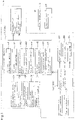
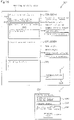
- Fig. 1 illustrates an overall view of a data communication system for a working machine.
- the data communication system 1 for a working machine is a system for making data communication between the working machine 2 such as a tractor, backhoe, combine harvester, or transplanter, and a mobile terminal 3.
- the mobile terminal 3 is a PDA (Personal Data Assistance), a tablet PC, or the like that is easily carried and can make wireless communication, and includes a smartphone or mobile phone having a telephone function. Also, the mobile terminal 3 is one that can, through the data communication, transmit a control program and control parameter necessary for the working machine to the working machine and obtain information the working machine has.
- PDA Personal Data Assistance
- tablet PC tablet PC
- the mobile terminal 3 is one that can, through the data communication, transmit a control program and control parameter necessary for the working machine to the working machine and obtain information the working machine has.
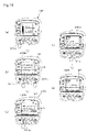
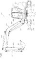
- the working machine 2 that can make wireless communication with the mobile terminal 3 is described in detail by taking a tractor as an example.
- the tractor 2 is configured such that on a traveling car body 10 having wheels in front and rear parts, an engine (e.g., a diesel engine) 11, a transmission 12, a control device 13, and the like are mounted.
- an engine e.g., a diesel engine
- a transmission 12 e.g., a transmission 12
- a control device 13 e.g., a control device 13
- a three-point link mechanism 14 is provided so as to be movable up and down.
- Various types of working units (in the illustrated example, a cultivator) 15 can be attached/detached to/from the three-point link mechanism 14.
- the working unit 15 is adapted such that power from the engine 11 is transmitted thereto through a PTO shaft.
- a cabin 16 of an independently mounted type is provided, and inside the cabin 16, a driver's seat 17 is provided.
- a display device 18 for displaying various pieces of information on the tractor 2 is provided.
- the display device 18 is, differently from the mobile terminal 3, fixed around the driver's seat 17 of the tractor 2, and when an operator sits on the driver's seat 17, the operator can visually recognize content displayed on the display device 18 from the driver's seat 17.
- the display device 18 is a fixed type display device.
- Such a tractor 2 is adapted to be able to travel and work with the working unit 15.
- the control device 13 is one that, in the tractor 2, controls a traveling system and a working system, and configured to include a CPU and the like. In the tractor 2, the traveling system control and the working system control are performed by a plurality of (e.g., two) control devices 13A and 13B. Note that the present embodiment is adapted to control the tractor 2 with the plurality of control devices 13A and 13B; however, the number of control devices 13 may be one or more.
- the first control device 13A is one that controls the whole of the tractor 2, and adapted to be able to make mutual communication with the other control device 13B, i.e., the second control device 13B through an in-car communication network such as CAN (Controller Area Network) or FlexRay.
- CAN Controller Area Network
- FlexRay FlexRay
- the first control deice 13A is adapted to be inputted with an accelerator pedal operation amount at the time of operating an accelerator pedal, a shift lever position at the time of operating a transmission shift lever, and the like.
- the first control device 13A is adapted to be able to output a control instruction to the second control device 13B on the basis of the accelerator pedal operation amount so as to control the engine 11 to have a predetermined rotation number, and also control the transmission 12 (performing transmission control) on the basis of the shift lever position.
- the first control device 13A is adapted to be inputted with an engine rotation upper limit, an accelerator lever amount, an engine rotation number, and the like.
- the engine rotation upper limit is adapted to be settable by a control provided near the driver's seat 17, and the accelerator lever amount is adapted to be settable by an accelerator lever provided near the driver's seat 17.
- the first control device 13A In the case where the engine rotation upper limit is inputted, the first control device 13A outputs a control instruction to the second control device 13B so as to prevent a rotation number of the engine 11 from exceeding the engine rotation upper limit.
- the first control device 13A is adapted to output a control instruction according to the accelerator pedal operation amount to the second control device 13B when the accelerator pedal operation amount is equal to or more than the accelerator lever amount, whereas when the accelerator pedal operation amount is less than the accelerator lever amount, the first control device 13A is adapted not to issue the control instruction according to the accelerator pedal operation amount to prevent the control of the rotation number of the engine 11 according to the accelerator pedal operation amount.
- the first control device 13A controls the display device 18 that displays various pieces of information on the tractor 2, such as the engine rotation number, a transmission gear level, oil temperature, and also, on the basis of input from an operating member, controls the upward and downward movements of the three-point link mechanism 14 (3P up-and-down control) .
- the second control device 13B (engine computer unit) is one that mainly controls the engine 11, and on the basis of input of the accelerator pedal operation amount, crank position, cam position, and the like outputted through the first control device 13A, controls an injector 27, common rail 28, supply pump 29, and the like.
- the engine control in the second control device 13B is the same as typical diesel engine control, and for example, by the control of the injector 27, a fuel injection quantity, injection timing, and a fuel injection rate are set, and by the control of the supply pump 29 and common rail 28, a fuel injection pressure is set.
- the above-described first control device 13A and second control device 13B can control the traveling system and working system of the tractor 2. Note that the control of the traveling system and working system of the tractor 2 is not limited to the above-described one.
- the first control device 13A is provided with a communication part (transceiver part) 30 for making the data communication with the mobile terminal 3 through the wireless communication.
- the present invention is systemized to determine whether or not to allow the data communication between the first control device 13A and the mobile terminal 3, and in the case where the data communication is allowed, to make the data communication, and in the case where the data communication is not allowed, not to make the data communication.
- a working machine-use ID code which is stored in the first control device 13A
- a mobile-use ID code which is stored in the mobile terminal 3
- the working machine-use ID code is assigned to each tractor 2 (working machine 2), i.e., specific to the tractor 2; and for example, stored (saved) in a storage part 31 of the first control device 13A at the time of manufacturing the tractor 2 by a manufacturing company that manufactures the tractor 2.
- the mobile-use ID code is preliminarily stored in a storage part 32 of the mobile terminal 3 by after-mentioned ID code registration means 45.
- the storage part 31 of the first control device 13A and the storage part 32 of the mobile terminal 3 are respectively configured to include, for example, nonvolatile memories.
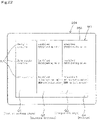
- the first control device 13A is provided with ID code obtaining means 40, ID code checking means 41, and data communication means 42.
- the ID code obtaining means 40, ID code checking means 41, and data communication means 42 are respectively configured to include programs and the likes stored in the first control device 13A.
- the ID code obtaining means 40 is means adapted to obtain the mobile-use ID code from the mobile terminal 3 through the wireless communication.
- the ID code checking means 41 is means adapted to check the mobile-use ID code and the working machine-use ID code with each other. In the case where the matching between the ID codes checked by the ID code checking means 41 is established, the data communication means 42 brings the mobile terminal 3 and the first control device 13A into a data communicable state (enabled state), and in the case where the matching is not established, brings the mobile terminal 3 and the first control device 13A into a data incommunicable state (disabled state).
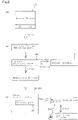
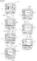
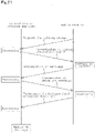
- a menu for "Obtain ID code” is displayed on the display device 18. Then, when the menu for "Obtain ID code” is selected by the switch or the like, as illustrated in Fig. 2(b) , the ID code obtaining means 40 is activated.
- the ID code obtaining means 40 When the ID code obtaining means 40 is activated, first, in order to make an ID code request outside through the transceiver part 30, a signal is transmitted to search for a wirelessly communicable mobile terminal 3. Then, in the case where there is a response from the mobile terminal 3, the ID code obtaining means 40 makes a request for a mobile-use ID code to the mobile terminal 3, and obtains the mobile-use ID code transmitted from the mobile terminal 3.
- the ID code checking means 41 is activated, and the working machine-use ID code, which is stored in the storage part 31 of the first control device 13A is called up by the ID code checking means 41. Then, the ID code checking means 41 checks the called-up working machine-use ID code and the mobile-use ID code with each other.
- timing to check the ID codes by the ID code checking means 41 is only required to be timing to make the data communication between the working machine 2 and the mobile terminal 2, and a method for the checking is not limited to the method illustrated in Fig. 2 .
- the ID code checking means 41 determines that the matching between the ID codes is established because the mobile-use ID code and the working machine-use ID code coincide with each other. In the case where the mobile-use ID code and the working machine-use ID code does not coincide with each other, the ID code checking means 41 determines that the matching between the ID codes is not established.
- the data communication means 42 continues the wireless communication between the first control device 13A (transceiver part 30) and the mobile terminal 3, and also by enabling data transmission from the first control device 13A to the mobile terminal 3 as well as enabling reception of data transmitted from the mobile terminal 3, brings the both into the state where the data communication can be made.
- first control device 13A and the other control device mounted in the tractor 2 can make the mutual data communication through the CAN, and therefore in the data communicable state, data of the other control device can also be transmitted through the first control device 13A, and the other control device can receive data of the mobile terminal 3 through the first control device 13A.
- the data communication means 42 brings the both into the state where the data communication cannot be made.
- the data communication means 42 locks the data communication so as to prevent data from being bi-directionally communicated between the control device 13A and the mobile terminal 3.
- only the mobile-use ID code and a registration code are preferably configured to be receivable.
- the first control device 13A is provided with data writing means 43, data distribution means 44, and the ID code registration means 45.
- the data writing means 43, data distribution means 44, and ID code registration means 45 are respectively configured to include programs and the likes stored in the first control device 13A.
- the data writing means 43 is one that, in the state where the data communication means 42 makes it possible to make the data communication between the mobile terminal 3 and the first control device 13A, writes data transmitted from the mobile terminal 3.
- the data distribution means 44 is one that, as with the data writing means 43, in the data communicable state, distributes (outputs) data to the mobile terminal 3.
- the switch or the like of the display device 18 is operated to display a writing content selection screen for selecting content of the data writing.
- a menu for selecting content of the data writing is displayed, and the menu including, for example, "Write control program” and "Write control parameter" is displayed.
- a device selection screen for selecting a device (writing target device) for which a control program or a control parameter is written is displayed.
- the device selection screen for example, "First control device”, “Second control device”, and “Display device” are displayed.
- the data writing means 43 makes a control program, which corresponds to a writing target device selected on the device selection screen, receivable from the mobile terminal 3 to the first control device 13A (transceiver part 30), and when receiving the control program transmitted from the mobile terminal 3, rewrites a control program for the device selected on the device selection screen.
- This enables a control program or the like to be freely rewritten as long as the control program and a control parameter for a device or the like mounted in the tractor 2 are stored in the mobile terminal 3.
- an output content selection screen for selecting output content of data is displayed.
- a menu for selecting the data output content is displayed.
- the operation control information refers to information that records an engine driving time of the tractor 2 on a date basis
- the failure history refers to a history that records failure time and a failure part with relating the failure time and the failure part to each other.
- the data distribution means 44 transmits content (operation control information or failure information) selected on the output content selection screen from the first control device 13A (transceiver part 30) to the mobile terminal 3.
- content operation control information or failure information
- the data distribution means 44 transmits content (operation control information or failure information) selected on the output content selection screen from the first control device 13A (transceiver part 30) to the mobile terminal 3.
- This enables data stored in the tractor 2 to be freely transmitted to the mobile terminal 3.
- pieces of output content may include, in addition to the operation control information and the failure history, any data as long as the data is on the tractor 2.
- the ID code registration means 45 is one that registers the working machine-use ID code in the mobile terminal 3 as the mobile-use ID code so as to establish the matching between the mobile-use ID code and the working machine-use ID code.
- the ID code registration means 45 relates the mobile-use ID code and the working machine-use ID code to each other to thereby enable the matching between the ID codes to be established.
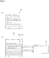
- an ID code registration screen is displayed.
- the ID code registration screen first enters an input mode in which a registration code for allowing registration is inputted.
- the registration code is preliminarily set for each tractor 2 separately from the working machine-use ID code or the mobile-use ID code, and unless the registration code is known, the working machine-use ID code cannot be registered in the mobile terminal 3 as the mobile-use ID code.
- the registration code is preliminarily stored in the storage part 31 of the first control device 13A.
- the registration code is controlled by a manufacturing company that manufactures the tractor 2, a sales company that sells the tractor 2, and a rental company that rents the tractor 2, and in the case of registering the ID code, a user or the like obtains the registration code from any of these companies in advance.
- the ID code registration means 45 checks the inputted registration code with the registration code stored in the storage part 31 of the first control device 13A.
- the ID code registration means 45 displays, on the ID code registration screen, "Checking completed” indicating that the matching is established, and then allows the ID code registration to transmit the working machine-use ID code stored in the storage part 31 of the first control device 13A and a registration allowance signal to the mobile terminal 3 through the transceiver part 30.
- the ID code registration means 45 does not transmit the working machine-use ID code to the mobile terminal 3, and therefore the ID code cannot be registered.
- the mobile terminal 3 upon receipt of the working machine-use ID code and the registration allowance signal that are transmitted from the tractor 2, i.e., the first control device 13A, the mobile terminal 3 stores the transmitted working machine-use ID code in the storage part 32 of the mobile terminal 3 as the mobile-use ID code.
- the storage part 32 of the mobile terminal 3 may be adapted to be able to store a plurality of mobile-use ID codes.
- ID code registration means 45 is used to relate a plurality of tractors 2 to one mobile terminal 3
- data communication with the plurality of tractors 2 can be made by the one mobile terminal 3.
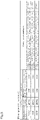
- working machine-use ID codes of the respective tractors 2 are "M13510006", “M13510007”, and "M1351008".
- the user can use the mobile terminal 3 to make data communication with the two tractors 2 of the three tractors 2.
- the ID code registration screen may be displayed on the mobile terminal 3.
- the ID code registration screen is displayed on a display screen of the mobile terminal 3.
- a program for displaying the ID code registration screen may be preliminarily stored in the mobile terminal 3, or obtained from the tractor 2 at the time of ID code registration through wireless communication.
- the ID code registration means 45 checks the inputted registration code and a registration code stored in the storage part 31 of the first control device 13A with each other, and in the case where matching between the registration codes is established, allows ID code registration to transmit a working machine-use ID code stored in the storage part 31 of the first control device 13A and a registration allowance signal to the mobile terminal 3 through the transceiver part 30. In the case where the matching between the registration codes is not established, the ID code registration means 45 does not transmit the working machine-use ID code to the mobile terminal 3, and therefore the ID code cannot be registered.
- the above-described ID code obtaining means 40, ID code checking means 41, data communication means 42, ID code registration means 45, data writing means 43, and data distribution means 44 are not provided in the first control device 13A, but may be provided in another control device mounted in the tractor 2, for example, in the second control device. Also, the ID code obtaining means 40, ID code checking means 41, data communication means 42, ID code registration means 45, data writing means 43, and data distribution means 44 are not all provided in one control device, but may be provided with being dispersed in corresponding control devices.
- control device is provided with the ID code checking means 41 and the data communication means 42, so that only in the case where matching between ID codes is established, data communication between the working machine 2 and the mobile terminal 3 becomes possible, and therefore security of the data communication in the working machine 2 can be improved.
- the mobile terminal 3 can be used to freely make data communication with the specific working machine 2.
- control device is provided with the ID code registration means 45, so that a mobile terminal 3 that can make data communication with a specific working machine 2 can be added, and therefore a plurality of mobile terminals 3 can be used to make data communication with the one working machine 2. Further, the control device is provided with the data writing means 43 and the data distribution means 44, and therefore writing, rewriting, and distribution (output) of data of the control device can be easily performed.
- ID codes are checked with each other in the control device of the working machine 2; however, the ID codes may be checked with each other in the mobile terminal 3.
- the mobile terminal 3 obtains a working machine-use ID code from the control device to check the obtained working machine-use ID code with a mobile-use ID code.
- the present invention may be adapted such that in the case where matching is established in the mobile terminal 3, the mobile terminal 3 allows data communication between the mobile terminal 3 and the control device, whereas in the case where the matching is not established, the mobile terminal 3 does not allow the data communication. That is, the mobile terminal 3 may be provided with the ID code checking means 41 and the data communication means 42.
- a method for obtaining a registration code is not particularly limited; however, the present invention may be adapted to, for example, use the mobile terminal 3 to access a management server of any of the manufacturing company, sales company, and rental company, and make user registration in the management server to thereby obtain the registration code from the management server.
- the manufacturing company stores a working machine-use ID code on a working machine side 2 (in a control device or the like) at the time of manufacturing the working machine 2; however, the present invention may be adapted to be able to, with use of the display device 18 or the like, manually store the working machine-use ID code in the control device or the like.
- coincidence between a mobile-use ID code and a working machine-use ID code is set as a condition for matching establishment; however, in the case where a mobile-use ID code stored in the mobile terminal 3 and a working machine-use ID code stored on the working machine side are related to each other, the ID codes may be treated on the assumption that matching is established.
- an encryption code used to make data communication between the working machine side and the mobile terminal side may be used as a working machine-use ID code or a mobile-use ID code, or an encryption code that changes with time may be used as a working machine-use ID code or a mobile-use ID code.
- a mobile-use ID code used to make data communication may be one that is temporarily stored in the storage part 32 when, for example, the data communication is made (only when ID code checking is performed).
- the ID code registration means 45 registers a working machine-use ID code in the mobile terminal 3 so as to be able to relate the working machine-use ID code as a mobile-use ID code, and then after ID code checking, the registered mobile-use ID code is automatically erased.
- the mobile-use ID code may be one that is not erased after the ID code checking but stored in the storage part 32 over a long period of time even after the ID code checking (even after the end of data communication).
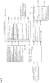
- Fig. 7 illustrates an overall view of an operation system for a working machine.
- the working machine operation system 101 is provided with: a management server 103 that manages the working machine 102; a mobile terminal 104 that can make wireless communication with the working machine 102 and the management server 103; and a control device 105 that is provided in the working machine 102.
- the working machine operation system 101 is one that, when a user or the like using the working machine 102 makes user registration, transmits a mobile-use ID code from the management server 103 to the mobile terminal 104 through a network, and uses the mobile-use ID code transmitted to the mobile terminal 104 to or not to allow operation of the working machine 102.
- the mobile terminal 104 is a PDA (Personal Data Assistance), a tablet PC, or the like that is easily carried and can make wireless communication, and includes a smartphone or mobile phone having a telephone function.
- PDA Personal Data Assistance
- the mobile terminal 104 is provided with: data storage means 107 adapted to store the mobile-use ID code or the like transmitted from the management server 103; and data transmitting means 8 adapted to transmit the mobile-use ID code stored in the data storage means 107 to the working machine 102.
- the data storage means 107 is configured to include a nonvolatile memory and the like, and the data transmitting means 8 is configured to include a program and the like.
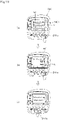
- the tractor 102 is configured such that, on a traveling car body 110 having wheels in front and rear parts, an engine (e.g., a diesel engine) 111, a transmission 112, the control device 105, and the like are mounted.
- an engine e.g., a diesel engine
- a transmission 112 the control device 105
- the like On a rear side of the traveling car body 110, a three-point link mechanism 114 is provided so as to be movable up and down.
- Various types of working units (in the illustrated example, a cultivator) 115 can be attached/detached to/from the three-point link mechanism 114.
- the working unit 115 is adapted such that power from the engine 111 is transmitted thereto through a PTO shaft.
- a cabin 116 of an independently mounted type is provided, and inside the cabin 116, a driver's seat 117 is provided.
- a display device 118 for displaying various pieces of information on the tractor 102 is provided.
- the display device 118 is, differently from the mobile terminal 104, fixed around the driver's seat 117 of the tractor 102, and when an operator sits on the driver's seat 117, the operator can visually recognize content displayed on the display device 118 from the driver's seat 117.
- Such a tractor 102 is adapted to be able to travel and work with the working unit 115.
- the control device 105 is one that controls a traveling system and a working system in the tractor 102, and configured to include a CPU and the like.
- the traveling system and the working system are controlled by a plurality of (e.g., two) control devices 105A and 105B.
- the present embodiment is adapted to control the tractor 102 with the plurality of control devices 105A and 105B; however, the number of control devices 105 may be one or more.
- the first control device 105A is one that controls the whole of the tractor 102, and adapted to make mutual communication with the other control device 105B, i.e., the second control device 105B through an in-car communication network such as CAN (Controller Area Network) or FlexRay. Also, the first control device 105A is adapted to be provided with a communication part (transceiver part) 130 for making wireless communication with the mobile terminal 104 such as a PDA (Personal Data Assistance) that is easily carried and can make the wireless communication, and able to make the wireless communication with the mobile terminal 104 through the communication part.
- a communication part 130 for making wireless communication with the mobile terminal 104
- PDA Personal Data Assistance
- the first control device 105A is adapted to be inputted with an accelerator pedal operation amount at the time of operating an accelerator pedal, a shift lever position at the time of operating a transmission shift lever, and the like.
- the first control device 105A is adapted to be able to output a control instruction to the second control device 105B on the basis of the accelerator pedal operation amount so as to control the engine 111 to have a predetermined rotation number, and also control the transmission 112 (performing transmission control) on the basis of the shift lever position.
- the first control device 105A is adapted to be inputted with an engine rotation upper limit, an accelerator lever amount, an engine rotation number, and the like.
- the engine rotation upper limit is adapted to be settable by a control provided near the driver's seat 117
- the accelerator lever amount is adapted to be settable by an accelerator lever provided near the driver's seat 117.
- the first control device 105A outputs a control instruction to the second control device 105B so as to prevent the rotation number of the engine 111 from exceeding the engine rotation upper limit. Also, in the case where the accelerator lever amount is inputted, the first control device 105A is adapted to output a control instruction according to the accelerator pedal operation amount to the second control device 105B in the case where the accelerator pedal operation amount is equal to or more than the accelerator lever amount, whereas in the case where the accelerator pedal operation amount is less than the accelerator lever amount, the first control device 105A is adapted not to issue the control instruction according to the accelerator pedal operation amount to prevent the control of the rotation number of the engine 111 according to the accelerator pedal operation amount.
- the first control device 105A controls the display device 18 that displays various pieces of information on the tractor 102, such as the engine rotation number, a transmission gear level, oil temperature, and also, on the basis of input from an operating member, controls the upward and downward movements of the three-point link mechanism 114 (3P up-and-down control).
- the second control device 105B (engine computer unit) is one that mainly controls the engine 111, and on the basis of input of the accelerator pedal operation amount through the first control device 105A, crank position, cam position, and the like, controls an injector 127, a common rail 128, a supply pump 129, and the like.
- the engine control in the second control device 105B is the same as typical diesel engine control, and for example, by the control of the injector 127, a fuel injection quantity, injection timing, and a fuel injection rate are set, and by the control of the supply pump 129 and common rail 128, a fuel injection pressure is set.
- the first control device 105A and the second control device 105B can control the traveling system and working system of the tractor 102. Note that the control of the traveling system and working system of the tractor 102 is not limited to the above-described one.
- Such a tractor 102 is adapted, in the case where matching between a mobile-use ID code transmitted from the mobile terminal 104 and a preliminarily stored working machine-use ID code is established, to allow the control by the control devices 105 to make the tractor 102 operable, and on the other hand, in the case where the matching is not established, not to allow the control to restrict the operation of the tractor 102.
- the ID codes are checked with each other by the first control device 105A or the second control device 105B.
- the first control device 105A is taken as an example to provide a description.
- the first control device 105A is provided with ID code obtaining means 140, ID code checking means 141, and control restriction means 142.
- the ID code obtaining means 140, ID code checking means 141, and control restriction means 142 are respectively configured to include programs and the likes stored in the first control device 105.
- the ID code obtaining means 140 is one that obtains a mobile-use ID code from the mobile terminal 104 through wireless communication.
- the ID code checking means 141 is one that checks the mobile-use ID code transmitted from the mobile terminal 104 and a working machine-use ID code stored on the tractor 102 side.
- the working machine-use ID code is one that is assigned to each tractor 102 (working machine 2), i.e., specific to the tractor 2, and for example, stored (saved) in a storage part 143 of the first control device 105A.
- the storage part 143 is configured to include, for example, a nonvolatile memory.
- the working machine-use ID code is preliminarily written in the storage part 143 at the time of manufacturing the tractor 102 by a manufacturing company that manufactures the tractor 102.
- the mobile-use ID code is one that is stored in the storage part (data storage means 107) of the mobile terminal 104, and for example, transmitted from the management server 103 (ID code transmitting means 151) and written in the storage part 107.
- the ID code obtaining means 140 is activated to wait for transmission of the mobile-use ID code from the mobile terminal 104.
- the ID code obtaining means 140 obtains the mobile-use ID code transmitted from the mobile terminal 104.
- the ID code checking means 141 calls up the working machine-use ID code stored in the storage part 143 of the first control device 105A to check the called-up working machine-use ID code and the obtained mobile-use ID code with each other.
- the ID code checking means 141 determines that matching between the ID codes is established, because the mobile-use ID code and the working machine-use ID code coincide with each other. In the case where the mobile-use ID code and the working machine-use ID code does not coincide with each other, the ID code checking means 141 determines that the matching between the ID codes is not established.
- control restriction means 142 allows the control by the control devices 105 to perform normally performed control (normal control) without control restriction.
- control restriction means 142 transmits an allowance signal, which allows control, to all of the control devices 105, and the respective control devices 105 performs the normal control on driving parts such as the engine 111, transmission 112, and three-point link mechanism 116 according to operations of the tractor 102.
- the control restriction means 142 does not allow the control by the control devices 105 (sometimes referred to as "control not allowed") to place a restriction on the control.
- a non-allowance signal which does not allow the normal control, is transmitted to part or all of the control devices 105 (a signal indicating "control not allowed" is transmitted). At least one control device 105 having received the non-allowance signal partially or wholly stops or restricts control.
- the second control device 105B having received the non-allowance signal makes the accelerator pedal control amount zero (makes the accelerator pedal inoperable). That is, in the case where "control not allowed" is given by the control restriction means 142, the second control device 105B does not perform the normal control corresponding to the accelerator pedal, and an engine operation is restricted to prevent the tractor 102 from traveling.
- the stop or restriction of the normal control of the operation parts by the respective control devices 105 is not limited to the above-described one.
- the first control device 105A is adapted to control the transmission (operation part) on the basis of the shift lever position; however, the first control device 105A may be adapted, in the case of "control not allowed", not to perform the normal control of the transmission 12 based on the shift lever position, or not to perform the normal control of the three-point link mechanism 116 (operation part). To stop or restrict the normal control, it is preferable to partially or wholly stop control of the engine to prevent the tractor 102 from traveling.
- the mobile-use ID code is transmitted from the mobile terminal 104 to the tractor 102 to check the ID codes with each other, and in the case where the matching between the ID codes is established, the tractor 102 can be operated.
- the engine operation and the like of the tractor 102 can be restricted.
- the operation system 101 for the working machine is one that is adapted to require user registration in order to obtain the above-described mobile-use ID code, and then after the completion of the user registration, transmit the ID code from the management server 103 to a desired mobile terminal 104.
- the user registration refers to registering (storing) information on a user who uses the tractor 102 or has purchased the tractor 102 in the management server 103.
- the management server 103 is installed in the manufacturing company that manufactures the tractor 102, a sales company that sells the tractor 102, a rental company that rents the tractor 102, a finance company that pays for the tractor 102 in place of the user, or another companies. That is the management server 103 is installed in a company that requires the user registration.
- the management server 103 is provided with: user information storage means 150 adapted to store various pieces of information on the user registration; and ID code transmitting means 151 adapted to, after completion of the user registration, transmit the mobile-use ID code to the mobile terminal 104.
- the user information storage means 150 is configured to include a database and the like, and the ID code transmitting means 151 is configured to include a program and the like stored in the management server 103.
- the database 150 mainly stores pieces of information on tractors 102 (pieces of tractor information) and pieces of information on users (pieces of user information) with respectively relating the pieces of tractor information and the pieces of user information to each other.
- the database 150 stores, as the pieces of tractor information, working machine-use ID codes for respectively identifying tractors 102.
- the database 150 stores, as the pieces of user information, mobile-use ID codes, and names, addresses, mail addresses of mobile terminals 104, and phone numbers of the mobile terminals 104 of the users, and the like.
- the user registration is adapted to relate tractor information and corresponding user information to each other.
- a user uses a mobile terminal 104 to access the management server 103.
- a registration format R is prepared, and to enable pieces of necessary information to be inputted in the registration format R, on a display screen of the mobile terminal 104, the registration format R is displayed.
- the registration format R is adapted to be able to be inputted with a purchase date of the tractor 102 that the user purchased, a model number of the tractor 102, a working machine-use ID code of the tractor 102, and a name, an address, a mail address of the mobile terminal 104, and a phone number of the mobile terminal 104 of the user.
- the working machine-use ID code of the tractor 102 is preferably informed from the manufacturing company after the purchase of the tractor 102, i.e., when the tractor 102 is paid for, and for example, the working machine-use ID code is preferably stated in an instruction manual, warranty, and/or user registration guidebook of the purchased tractor 102.
- the management server 103 After such pieces of information have been inputted in the registration format R to complete the registration, in the management server 103, the purchase date of the tractor 102, the model number of the tractor 102, the working machine-use ID code of the tractor 102, and the name, address, mail address of the mobile terminal 104, and phone number of the mobile terminal 104, and the like of the user are stored with being related to one another.
- the management server 103 transmits a mobile-use ID code to the mobile terminal 104 related to the working machine-use ID code by the ID code transmitting means 151.
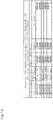
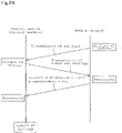
- Fig. 11(a) it is assumed that after a user A has purchased a tractor 102 having a working machine-use ID code of "M13510006" from the manufacturing company, the user A accesses the management server 103 to make user registration. Then, as illustrated in Fig. 11(b) , the ID code transmitting means 151 of the management server 103 transmits the same ID code ("M13510006") as the working machine-use ID code to a mobile terminal 104 that is registered in the user registration by the user A. As illustrated in Fig.
- the mobile terminal 104 upon receipt of the ID code ("M13510006") transmitted from the management server 103, the mobile terminal 104 obtains the ID code as a mobile-use ID code, and stores the obtained mobile-use ID code in a storage part (data storage means 107).
- the mobile-use ID code from the management server 103 may be automatically obtained when the mobile-use ID code to be stored in the mobile terminal 104 itself is transmitted with communication with the outside being monitored.
- the present invention may be adapted to provide the mobile terminal 104 with an ID code obtaining mode in advance; operate the mobile terminal 104 to thereby put the mobile terminal 104 in the ID code obtaining mode; and only when putting the mobile terminal 104 in the ID code obtaining mode, obtain the mobile-use ID code.
- the mobile terminal 104 can be identified by the mail address or phone number of the mobile terminal 104 inputted in the user registration. In the user registration, it is necessary to, in the management server 103, store information that identifies the mobile terminal 104; however, the information is not limited to the mail address or phone number of the mobile terminal 104, but may be any information as long as the information identifies the mobile terminal 104.
- a mobile-use ID code cannot be obtained, and therefore it becomes difficult for a third person other than a user who uses a working machine 102 to obtain an ID code for operating the working machine 102 and easily operate the working machine 102.
- the management server 103 of the manufacturing company or the like is accessed to surely make the user registration, the working machine 102 cannot be operated, and therefore it is very difficult to operate the working machine 102 before the purchase of the working machine 102, so that the working machine 102 can be surely prevented from being stolen before selling (purchasing).
- the user registration is made in the management server 103 of the manufacturing company; however, the user registration may be made in the management server 103 of the rental company that rents the working machine 102.
- the above-described second embodiment is adapted to, whenever matching between a mobile-use ID code and a working machine-use ID code is established, allow the normal control; however, a third embodiment is adapted to set an operation allowable time during which control (normal control) is allowed, and in the case where matching between ID codes is established within the operation allowable time, allow the control.
- control normal control
- the case of setting the operation allowable time is described in detail.
- ID code obtaining means 140 also obtains the operation allowable time when a mobile-use ID code is transmitted from a mobile terminal 104.
- the operation allowable time is one that is transmitted from a management server 130, and set for each specific tractor 102.
- a first control device 105A stores the obtained operation allowable time in a storage part 143 in the case where the obtained operation allowable time is for a working machine 102 (tractor 102) corresponding to the first control device 105A itself.
- the first control device 105A does not store the operation allowable time.
- the operation allowable time may be represented as a remaining time, or set as a period.
- the operation allowable time is represented as a remaining time
- the first control device 105A decreases the operation allowable time to update the operation allowable time stored in the storage part 143.
- the updated operation allowable time (remaining operation allowable time) is 70 hours.
- control restriction means 142 In the case where the operation allowable time (remaining operation allowable time) stored in the first control device 105A is not zero hours (within the operation allowable time), and matching between ID codes is established, control restriction means 142 outputs an allowance signal to enable the normal operation by respective control devices 105 to be performed. On the other hand, in the case where the operation allowable time (remaining operation allowable time) stored in the first control device 105A is zero hours (out of the operation allowable time), even in the case where the matching between ID codes is established, the control restriction means 142 does not output the allowance signal to disable the normal control by the respective control devices 105 from being performed.
- the control restriction means 142 allows the normal operation based on established ID code matching until the end of the operation allowable time (period) is reached. Also, in the case where the operation allowable time is set as a period, the control restriction means 142 allows the normal operation based on the established ID code matching until the period terminates.
- control restriction means 142 allows the normal control based on the established ID code matching until "June 30, 2011”
- the control restriction means 142 allows the normal control based on the established ID code matching until "7 July, 2011” that is the last day of the period.
- the management server 103 is preferably installed in a rental company or a finance company.
- a user makes user registration in the management server 103 of the rental company.
- the user first uses a mobile terminal 104 to access the management server 103 of the rental company, and inputs pieces of tractor information in a registration format R, such as a period of a rental (rental period), a model number of a tractor 102, and a store that rents the tractor 102 (rental store) .
- the user inputs pieces of user information such as a name, address, mail address of the mobile terminal 104, and phone number of the mobile terminal 104 of the user.
- the management server 103 of the rental company extracts pieces of rental information on a rentable tractor 102 (such as a model number of the tractor 102, working machine-use ID code of the tractor 102 to be rented, rental period of the tractor 102, and rental store of the tractor 102) from the pieces of information in the registration format R inputted at the time of the user registration, and pieces of information on tractors 102 stored in the management server 103.
- pieces of rental information on a rentable tractor 102 such as a model number of the tractor 102, working machine-use ID code of the tractor 102 to be rented, rental period of the tractor 102, and rental store of the tractor 102
- the management server 103 searches whether or not any tractor 102 meeting the conditions inputted in the registration format R is present, and in the case where a tractor 102 meeting the conditions in the registration format R is present, informs the mobile terminal 104 of the user or the like of the pieces of rental information (such as the model number, rental period, and rental store of the tractor 102) excluding the working machine-use ID code.
- ID code transmitting means 151 of the management server 103 transmits the working machine-use ID code (ID code for the working machine to be rented) corresponding to the tractor 102, which is the subject of the rental agreement, to the mobile terminal 104 of the user as a mobile-use ID code. Also, the ID code transmitting means 151 transmits the rental period as the operation allowable time together with the mobile-use ID code.
- Data storage means 107 of the mobile terminal 104 stores the working machine-use ID code (mobile-use ID code) and operation allowable time transmitted from the ID code transmitting means 151 of the rental management server 103 with relating the mobile-use ID code and the operation allowable time to each other.
- the data storage means 107 of the mobile terminal 104 stores “M13510006” as the mobile-use ID code as well as storing "1 June to 7 July, 2011” as the operation allowable time.
- the data transmitting means 8 of the mobile terminal 104 transmits, to the first control device 105A, "M13510006" as the mobile-use ID code as well as transmitting "1 June to 7 July, 2011” as the operation allowable time.
- a tractor 102 currently rented in the case where matching between ID codes is established within a period of, for example, 1 June to 7 July, 2011, a tractor 102 currently rented can be operated. In the case where a rental period has passed, or the ID code matching is not established, the operation of the tractor 102 can be surely restricted.
- the rental company is taken as an example to provide the description; however, in a fourth embodiment, a finance company that pays a purchase price of a tractor 102 in a lump sum in place of a user is taken as an example to provide a description.
- a payment schedule for the user to make a payment in installments to the finance company is created.
- pieces of price payment information such as the number of installments paid to the finance company by the user, due dates, and payment amounts are listed.
- user registration is made.
- a registration format R in addition to a tractor 102 purchase date when the user purchased the tractor 102, a model number of the tractor 102, a working machine-use ID code of the tractor 102, a name, an address, a mail address of a mobile terminal 104, and a phone number of the mobile terminal 104 of the user, the pieces of payment information listed in the payment schedule are inputted to complete the user registration.
- ID code transmitting means 151 of the management server 103 of the finance company transmits a first due date to the mobile terminal 104 as an operation allowable time as well as transmitting the working machine-use ID code as a mobile-use ID code.
- the mobile terminal 104 Upon receipt of the mobile-use ID code and the operation allowable time as described above, the mobile terminal 104 stores the mobile-use ID code and the operation allowable time in a storage part.
- the management server 103 of the finance company regards the user registration as being made again (not actually made), and transmits the working machine-use ID code as the mobile-use ID code as well as transmitting a new due date as the operation allowable time to the mobile terminal 104.
- the mobile terminal 104 Upon receipt of the new operation allowable time, the mobile terminal 104 updates the already stored operation allowable time.
- the user in the case where matching between the ID codes is established during a period during which the user repeatedly makes the payment, the user can operate the tractor 102 for which the user continues to make the payment. In the case where the payment is overdue and any of the due dates has passed, or the matching between the ID codes is not established, the tractor 102 can be surely restricted from being operated.
- the management server 103 of the finance company preferably sets the operation allowable time to a very large value (e.g., a few hundred years or more) to thereby enable the tractor 102 to be used for a long period of time regardless of payment.
- the working machine in any of the manufacturing company that manufactures the working machine, the rental company that rents the working machine, and the finance company that pays for the working machine in a lump sum in place of a user, unless user registration is made to obtain an ID code for operating the working machine, the working machine cannot be operated, and therefore the working machine can be prevented from being operated by a third person other than the user.
- the ID code for operating the working machine is transmitted to a mobile terminal that the user possesses, and therefore a third person can be prevented from using the ID code to operate the working machine.
- the condition for the operation can be applied to even the user.
- the tractor is taken as an example to provide the description; however, the working machine may be a backhoe, combine harvester, transplanter, or the like.
- the timing to check the ID codes by the ID code checking means 141 is preferably timing when the working machine 102 is used, for example, an engine 111 is started; however, the ID code checking is only required to be performed when a user or the like uses the working machine 102, and the timing is not limited to the starting time of the engine 111.
- Fig. 16 illustrates an overall view of a setting change system for a working machine.
- the setting change system 201 for a working machine is one that enables after-mentioned control devices 230 to make and change various settings of a working machine 202 through a display device 203 installed in the working machine 202, and also enables the control devices 230 to make and change the various settings of the working machine 202 even with use of another mobile terminal 204 different from the display device 203.
- the mobile terminal 204 is one that can make wireless communication with the display device 203 and the like.
- the mobile terminal 204 is a wireless device that can, through the mutual wireless communication with the display device 203, transmit data of the mobile terminal 204 to the display device 203, and receive data from the display device 203.
- the data communication between the mobile terminal 204 and the display device 203 enables settings of the working machine 202, which are set on the display device 203, to be transmitted to the mobile terminal 204, and settings set with the mobile terminal 204 in place of the display device 203 to be transmitted to the display device 203.
- the display device 203 is connected with a communication part (transceiver part) 228 for making the wireless communication with the mobile terminal 204, and can thereby make the data communication through the transceiver part.
- Such a mobile terminal 204 is a PDA (Personal Data Assistance), a tablet PC, or the like that is easily carried and can make wireless communication, and includes a smartphone or mobile phone having a telephone function.
- PDA Personal Data Assistance
- the backhoe 202 is provided with a traveling unit 210 as a lower unit and a revolving body 211 as an upper unit.
- a crawler type traveling unit that is adapted to be provided with a left and right pair of traveling bodies 212 respectively having crawlers made of rubber, and drive the both traveling bodies 212 with a traveling motor is employed. Also, a front part of the traveling unit 210 is provided with a dozer 213.
- the revolving body 211 has: a revolving base 215 that is supported on the traveling unit 210 through a revolving bearing 214 so as to be revolvable left and right around a vertical revolving pivot; and a working unit 216 (excavating unit) that is provided at a front part of the revolving base 215.
- a working unit 216 excavating unit
- a display device 203 that can display various pieces of information on the backhoe and also make various settings of the backhoe is installed (fixed).
- the working unit 216 is provided with: a swing bracket 221 that is supported by a support bracket 220 provided at the front part of the revolving base 215 with being offset slightly to the light of a horizontally central part so as to be swingable left and right around a vertical shaft center; a boom 222 that is vertically swingably supported by the swing bracket 221 with a base part side thereof being pivotally attached to the swing bracket 221 so as to be rotationally movable around a horizontal shaft center; an arm 223 that is supported by a fore end side of the boom 222 so as to be swingable back and forth with being pivotally attached to the fore end side so as to be rotationally movable around a horizontal shaft center; and a bucket 224 that is provided on a fore end side of the arm 223 so as to be operable in a scooping/dumping manner.
- the swing bracket 221 is swung by expansion and contraction of a swing cylinder that is provided inside the revolving base 215; the boom 222 is swung by expansion and contraction of a boom cylinder 225 that is set between the boom 222 and the swing bracket 221; the arm 223 is swung by expansion and contraction of an arm cylinder 226 that is set between the arm 223 and the boom 222; and the bucket 224 is subjected to the scooping/dumping operation by expansion and contraction of a bucket cylinder 227 that is set between the bucket 224 and the arm 23.
- actuators such as the swing cylinder, boom cylinder 224, arm cylinder 226, and bucket cylinder 227 are adapted to operate through control valves that can supply the operating oil to the respective actuators. Also, a pilot pressure on each of the control valves is adjusted by an operation of an after-mentioned operating member, an electromagnetic proportional valve, and the like, and thereby a flow rate of the operating oil toward the control valve is changed.
- the backhoe 202 is provided with the control devices 230 for controlling the backhoe 202, and the control devices 230 and the display device 203 are adapted to be able to make mutual communication (data exchange) through an in-car communication network such as CAN (Controller Area Network) or FlexRay.
- CAN Controller Area Network
- FlexRay FlexRay
- control devices 230 in the present embodiment perform various types of control such as auto-idle control (AI control), flow rate control, boom height control, and arm angle control.
- AI control auto-idle control
- flow rate control flow rate control
- boom height control boom height control
- arm angle control arm angle control
- the display device 203 is adapted such that settings (on/off of each control and setting values) having been already set can be changed thereon, such as a change in setting (on/off setting of each control) indicating whether or not each control in the control devices 230 should be operated, and a change in setting value such as an upper limit or a lower limit in each control.
- each control in the control devices 230, and the changes in settings on the display device 203 are described. Note that each control performed by any of the control devices 230 in the working machine 202 such as the backhoe 202 is not limited to any of various types of control described below.
- the AI control or the flow rate control is performed by one of the control devices, which is configured to include a CPU and the like (referred to as a first control device) 230A.
- the first control device 230A is inputted with various types of control signals such as operation amounts of the operating members (e.g., an operation lever 233 and an operation switch) for operating the various types of actuators such as the swing cylinder, boom cylinder 224, arm cylinder 226, and bucket cylinder 227, a governor angle (governor position) from a governor sensor, an operation amount (angle) of an accelerator lever, an on signal/off signal of an idle-switch (AI-SW), and an engine rotation number from an engine rotation sensor.
- operation amounts of the operating members e.g., an operation lever 233 and an operation switch
- actuators such as the swing cylinder, boom cylinder 224, arm cylinder 226, and bucket cylinder 227
- a governor angle governor position
- AI-SW idle-switch
- the AI control is one that, when the operating members for operating the arm 223 (arm cylinder 226), boom 220 (boom cylinder 224), and the like are operated, increases/decreases the engine rotation number according to the accelerator lever operation amount, and when the operating members are not operated, fixes the engine rotation number to that in an idling state.
- the AI control by the first control device 230A when the operation laver 233 is placed in a neutral position to input the on signal of the idle-switch, regardless of the accelerator lever operation amount, an idle signal is outputted to an auto-idle motor to drive the auto-idle motor, and the engine rotation number is controlled to the idling rotation number. Also, in the AI control by the first control device 230A, when the operation lever 233 is swung back and forth or left and right to input the off signal of the idle-switch, an operation signal is outputted to the auto-idle motor on the basis of an accelerator position signal to drive the auto-idle motor. When the auto-idle motor is driven, the governor lever is operated to control the engine rotation number to a rotation number corresponding to the accelerator lever.
- the flow rate control is one that operates the actuators according to the operation amounts of the operating members.
- the boom height control and the arm angle control are performed by a control device (second control device) 230B different from the first control device 230A.
- the second control device 230B is inputted with various types of control signals such as control signals respectively indicating an arm angle and a boom angle.
- the boom height control is one that, when a height of the boom 222 becomes a preset upper limit of the boom height, regardless of an operation of the operation lever 233, stops an upward operation of the boom 222.
- the height of the boom 222 is replaced by the boom angle, and on the basis of the boom angle, the height of the boom 222 is determined.
- the boom angle is inputted to the second control device 230B.
- the second control device 230B stops the upward operation of the boom by demagnetizing a solenoid of an electromagnetic proportional valve or an electromagnetic valve for supplying a pilot pressure (pilot oil) to a control valve for supplying the operating oil to the boom cylinder 224.
- the arm angle control is one that, when the arm angle reaches a predetermined upper limit or lower limit of the arm angle, regardless of an operation of the operation lever 233, stops a scooping operation of the arm 223. Specifically, in the arm angle control by the second control device 230B, when the arm 223 is subjected to the scooping operation by the operation lever 233, the arm angle is inputted to the second control device 230B.
- the second control device 230B stops the scooping operation of the arm 223 by demagnetizing a solenoid of an electromagnetic proportional valve or an electromagnetic valve for supplying a pilot pressure (pilot oil) to a control valve for supplying the operating oil to the arm cylinder 226.
- the display device 203 is adapted to be inputted with pieces of information (data) on the working machine 202. That is, the display device 203 is adapted to be inputted with the pieces of data inputted to the first control device 230A and the second control device 230B through the CAN communication, and in addition, inputted with pieces of data such as setting values necessary for display or setting.
- Fig. 17 is a diagram in which a display part of the display device 203 is viewed from a front side.
- the display part 240 of the display device 203 is configured to include: a fixed display part 240a that indicates a state of the backhoe 202 on the basis of lighting or extinction of lamps such as LEDs; and a liquid crystal display part (variable display part) 240b that is configured to include a liquid crystal and the like and displays various pieces of information by making a display variable. Also, the display part 240 is provided with a plurality of switches 241, and by operating the switches 241, various operations can be performed.
- the display device 203 has: a normal scree mode that is seen when an operator or the like operates the backhoe 202; and a setting screen mode that is seen when the operator or the like makes settings of the backhoe 202.
- a program that puts the display device 203 into the normal screen mode or the setting screen mode is stored in the control device 230, i.e., the first control device 230A or the second control device 230B, and by executing the program, the display device 203 is adapted to operate. This enables the settings to be changed by the control device 230 through the display device 203.
- the program that puts the display device 203 into the normal screen mode or the setting screen mode i.e., the program for changing the settings may be stored in the display device 203.
- the pieces of information (drive information) on the backhoe 202 such as a fuel (remaining amount) outputted from a fuel sensor, a water temperature outputted from a water temperature sensor, and the engine rotation number.
- the normal screen mode is only required to display information that is necessary for the operator to operate the backhoe 202, but, of course, not limited to one illustrated in Fig. 17 .
- the liquid crystal display part 240b may be adapted to display a flow rate of the operating oil that, when a figure indicating an equipped attachment or the operating lever is operated, flows through a corresponding one of the actuators.
- Figs. 18 to 20 are diagrams exemplifying a method for switching the display device 203 to the setting screen mode to change the settings of the backhoe 202.
- Fig. 18 illustrates a screen transition of the display device 203 in the case of changing a setting value of the upper limit or lower limit of the arm angle used for the arm angle control.
- a first switch 241a is pressed.
- the display device 203 is switched from the normal screen mode to the setting screen mode, and as illustrated in Fig. 18(b) , the liquid crystal display part 240b is switched to a setting screen M1 for making settings.
- a plurality of items N to be set are displayed, and every time the second switch 241b is pressed, a setting item to be selected can be changed by scrolling.
- a fifth switch 241e By pressing a fifth switch 241e, a setting item N can be determined.
- a setting item N of "Arm limitation setting” is selected.
- a guide display that provides guidance so as to bring the arm to a position desired to be newly set (limitation position) is provided, and by operating the arm with the operation lever to bring the arm to the desired upper limit position or lower limit position, and then pressing a third switch 241c, the upper limit or lower limit of the arm angle can be changed.
- the changed setting value (the upper limit or lower limit of the arm angle) is stored in a storage part 253 provided in any of the first control device 230A, second control device 230B, and display device 203.
- the control device 230 (30B) changes the arm angle setting according to the upper limit or lower limit of the arm angle stored in the storage part 253.
- Fig. 19 illustrates a screen transition of the display device 203 in the case of making a setting that enables or disables the arm angle control.
- a special operation of, while pressing the first switch 241a, rotating an engine starting cylinder provided in the backhoe 202 to turn an ignition key from off to on is performed.
- the display device 203 is put into the setting screen mode; the liquid crystal display part 240b is switched to the setting screen M1; and the plurality of setting items N are displayed on the setting screen M1.
- "Arm limitation change" is selected, and the fifth switch 241e is pressed.
- an item that enables the arm angle control and an item that disables the arm angle control are displayed on the setting screen M1.
- the arm angle control can be enabled or disabled.
- the setting of enabling or disabling the arm angle control is stored in the storage part 253.
- the control device 230 (30B) changes the arm angle setting according to the setting of enabling or disabling the arm angle control, which is stored in the storage part 253.
- Fig. 20 illustrates a screen transition of the display device 203 in the case of changing the idling rotation number in the AI control.
- a setting item N of "AI control" is selected.
- the setting screen M1 is switched to a screen for setting the idling rotation number, and by operations of some of the switches 241 and the like, a value of the idling rotation number displayed on the setting screen M1 is changed (increased/decreased). Then, by pressing the third switch 241c, the changed value (setting value) of the idling rotation number displayed on the setting screen M1 is set as a new idling rotation number.
- a guide display that provides guidance so as to move the accelerator (accelerator lever) to a maximum (MAX) position is provided on the setting screen M1.
- a guide display that provides guidance so as to move the accelerator to an idling position is provided on the setting screen M1.
- a display indicating that the setting of the idling rotation number is completed is provided on the setting screen M1.
- the changed idling rotation number (setting value) is stored in the storage part 253.
- the control device 230 (230A) changes a setting of the AI control according to the idling rotation number stored in the storage part 253.
- the various settings in the backhoe 202 can be changed, such as the change in upper or lower limit of the arm angle, the switching whether to enable or disable the arm angle control, and the change in idling rotation number in the AI control.
- the control device 230 by executing the program stored in the control device 230 to operate the display device 203 as described above, the settings of the backhoe 202 can be changed by the control device 230.
- the settings can be changed.
- the display device 203 and the mobile terminal 204 a description is provided in detail.
- control device 230 (the first control device 230A or the second control device 230B) is provided with means adapted to change the settings through the display device 203.
- change instruction transmitting means 250 and content receiving means 251 are provided in the first control device 230A.
- content storage means (storage part) 253 adapted to store changed settings is provided in the first control device 230A.
- the change instruction transmitting means 250 and the content receiving means 251 are respectively configured to include programs and the likes stored in the first control device 230A.
- the programs respectively constituting the change instruction transmitting means 250 and the content receiving means 251 are not only stored in the first control device 230A, but may also be stored in the second control device 230B or the display device 203. In other words, the second control device 230B or the display device 203 may be provided with the change instruction transmitting means 250 and the content receiving means 251.
- the change instruction transmitting means 250 is means adapted to transmit a change instruction signal that instructs the mobile terminal 204 to change settings.
- the change instruction transmitting means 250 transmits the change instruction signal.
- the change instruction transmitting means 250 does not transmit the change instruction signal to the mobile terminal 204 through the transceiver part.
- the change instruction transmitting means 250 transmits the change instruction signal to the mobile terminal 204.
- whether or not the backhoe 202 is in operation can be determined by sensor information or other information inputted to the control device 230.
- the change instruction transmitting means 250 may transmit settings already stored in the content storage means 253 together with the change instruction signal.
- the same settings (the arm angle control is "Enable” and the idling rotation number being "1050rpm") as the settings stored in the content storage means 253 are transmitted to the mobile terminal 204.
- the setting values of the backhoe 202 can be checked on the mobile terminal 204 side, and while seeing the setting values already set on the backhoe 202 side, the setting values can be changed.
- the change instruction transmitting means 250 may transmit the setting control program through the display device 203 together with the change instruction signal.
- the mobile terminal 204 informs the change instruction transmitting means 250 of not having the setting control program, upon receipt of the informing, the change instruction transmitting means 250 transmits the setting control program to the mobile terminal 204.
- the settings of the backhoe 202 can be made.
- the settings stored in the content storage means 253 may also be transmitted.
- the content receiving means 251 is means adapted to receive (obtain) settings that have been changed on the mobile terminal 204 side in response to the change instruction signal. For example, in the case where on the mobile terminal 204 side, the setting screen M1 is displayed to complete setting of the backhoe 202, and the settings having been changed on the mobile terminal 204 side are transmitted to the content receiving means 251, as illustrated in Fig. 21 , the content receiving means 251 receives the changed settings, which are transmitted from the mobile terminal 204, through the display device 203 to temporarily store the settings.
- the content receiving means 251 does not continuously receive all of the settings, but intermittently receives the settings at intervals with dividing the settings.
- the content receiving means 251 once suspends receiving the settings, and when loads of the processing are decreased, requests the mobile terminal 204 to transmit the settings and then again receives the settings transmitted from the mobile terminal 204.
- the content storage means 253 stores, as new settings, the settings changed on the mobile terminal 204 side. For example, when the backhoe 202 is not in operation, i.e., when the control processing and the display processing are respectively in low load states, as illustrated in Fig. 21 , the content storage means 253 rewrites already stored settings to the new settings taken in by the content receiving means 251. In addition, during rewriting the settings, it is better to temporarily disable the backhoe 202 from being operated.
- the settings received by the content receiving means 251 in the content storage means 253 it is preferable to check the settings received by the content receiving means 251 and the settings transmitted from the mobile terminal 204 with each other. For example, after the content receiving means 251 has received the settings, the received settings are sent back (transmitted) from the control device 230 to the mobile terminal 204 through the display device 203.
- the settings sent back from the display device 203 (control device 230) is referred to as "check-use settings”.
- the check use settings transmitted from the display device 203 (control device 230) and the settings (transmission-use settings) that are set in the mobile terminal 204 and transmitted to the display device 203 are checked with each other, and in the case where both of the settings coincide with each other, a coincidence signal indicating the coincidence of the settings is transmitted from the mobile terminal 204 to the control device 230 through the display device 203.
- the settings already transmitted from the mobile terminal 204 are stored as the new settings.
- the mobile terminal 204 transmits a noncoincidence signal indicating the noncoincidence of the settings to the control device 230 through the display device 203.
- the control device 230 side upon receipt of the noncoincidence signal, the settings already transmitted from the mobile terminal 204 are not stored as the new settings, and again the content receiving means 251 requests the mobile terminal 204 to transmit the settings (retransmission request), and the mobile terminal 204 again sends the settings upon the retransmission request. That is, between the display device 203 (control device 230) and the mobile terminal 204, it is checked whether or not both of the settings coincide with each other, and the above processing is repeated until both of the settings coincide with each other.
- the setting change request is made from the mobile terminal 204 to the control device 230; then on the basis of the request from the mobile terminal 204, the control device 230 transmits the change instruction signal; and further, on the mobile terminal 204 side, in response to the change instruction signal transmitted from the control device 230, the settings set on the mobile terminal 204 side are transmitted to the control device 230.
- the control device 230 transmits the change instruction signal; and further, on the mobile terminal 204 side, in response to the change instruction signal transmitted from the control device 230, the settings set on the mobile terminal 204 side are transmitted to the control device 230.
- the settings transmitted from the mobile terminal 204 may be directly received by the control device 230.
- the control device 230 For example, in the case where an amount of data on the settings transmitted from the mobile terminal 204 to the control device 230 is small, it is better to employ a method as illustrated in Fig. 24 .
- the mobile terminal 204 is provided with setting screen display means 260, change means 261, and settings transmitting means 262.
- the setting screen display means 260, change means 261, and settings transmitting means 262 are respectively configured to include programs and the like stored in the mobile terminal 204.
- the mobile terminal 204 has a display part 263 for displaying the setting screen M1.
- the display part 263 may be one of a touch panel type as will be described later, or besides, may be one not of the touch panel type as long as being able to display various pieces of information.
- the setting screen display means 260 is one that, in response to the change instruction signal, displays the setting screen M1 for changing settings on the display part 263. For example, upon receipt of the change instruction signal transmitted from the control device 230 through the display device 203, the setting screen display means 260 activates the setting control program for displaying the setting screen M1 to display the setting screen M1 on the display part 263 of the mobile terminal 204.
- the setting screen display means 260 activates the stored setting control program to display the setting screen M1 on the display part.
- the setting screen display means 260 downloads the setting control program that is transmitted from the display device 203 (control device 230) together with the change instruction signal, and activates the downloaded setting control program to display the setting screen M1 on the display part.
- the setting screen M1 in the mobile terminal 204 may be adapted to be, as described above, completely the same screen (characters, numerical values, design, size, display range, and the like are all the same) as the setting screen M1 of the display device 203, or may also be adapted to be a screen that collectively displays a plurality of divided displays on the setting screen M1 of the display device 203.
- a list of all of the setting items N is displayed; in the center part, already set settings (existing settings) of the respective setting items N are displayed; in the right side part, changed settings (settings set with the mobile terminal 204) are displayed, and in the lower side part, guidance (message) is displayed. That is, the mobile terminal 204 divides the one setting screen M1 into the plurality of areas, and in the respective divided areas, displays the list of the setting items, existing settings, changed settings, message, and the like.
- a part that displays the list of the setting items is referred to as a first area Q1; a part that displays the existing settings is referred to as a second area Q2; a part that displays the changed settings is referred to as a third area Q3; and a part that displays the guidance is referred to as a fourth area Q4.
- the setting screen display means 260 displays the received existing settings in the second area Q2, and in the case where the settings are not received, does not display the existing settings in the second area Q2.
- the change means 261 is one that changes the settings displayed on the setting screen M1.
- the change means 261 pops up the setting corresponding to the touched setting item on the setting screen M1 to make the setting item changeable on a pop-up screen.
- the change means 261 displays the idling rotation number on the pop-up screen.
- the change means 261 automatically displays a numerical keypad for changing a numerical value of the idling rotation number.
- the idling rotation number can be changed.
- the change means 261 can freely change the settings displayed on the setting screen M1.
- the touch panel is taken as an example to provide the description; however, the change means 261 may be adapted to change the settings displayed on the setting screen M1 by operating a switch or the like or by making a speech sound, and the change means 261 may be any means as long as the means can change the settings.
- the settings transmitting means 262 is means adapted to transmit a setting changed on the setting screen M1 to the display device 203 (control device 230). For example, by touching a display indicating setting completion displayed on the setting screen M1 in the mobile terminal 204, the setting changed by the change means 261 is transmitted to the control device 230 through the display device 203.
- the settings transmitting means 262 is means adapted to, in the case where the setting completion is indicated, transmit the setting to the display device 203 (control device 230).
- a method for indicating the setting completion may be any method such as a method that touches the display indicating the setting completion as described above, a method using a switch or the like to make the indication, or a method using a speech sound to make the indication.
- the mobile terminal 204 may be provided with content checking means adapted to, as described above, check the check-use settings transmitted from the display device 203 (control device 230) and the transmission-use settings on the mobile terminal 204 side with each other.
- the mobile terminal 204 transmits the coincidence signal indicating the coincidence of the settings to the display device 203 (control device 230), and in the case where both of the settings do not coincide with each other, transmits the noncoincidence signal indicating the noncoincidence of the settings to the display device 203 (control device 230).
- the settings transmitting means 262 retransmits the settings.
- the settings transmitting means 262 repeatedly transmits the settings until both of the settings coincide with each other.
- the change instruction transmitting means 250, the content receiving means 251, and the content storage means 253 are provided, and therefore with a worker operating the working machine 202 holding the mobile terminal 204 at hand, the worker can easily change settings of the working machine 202 only by operating the mobile terminal 204.
- the change instruction transmitting means 250 is configured to transmit settings already stored on the working machine 202 side to the mobile terminal 204, so that when the worker changes settings, the worker can change the settings to new settings while seeing the settings before the change, and therefore the worker easily plans how to change the settings from the current situation and even in this regard, can easily make the settings.
- the change instruction transmitting means 250 is configured to transmit the program (setting control program) for displaying the setting screen M1 to the mobile terminal 204, and therefore even in the case where the mobile terminal 204 possessed by the worker does not have the setting control program, the worker can change the settings.
- the content checking means adapted to check the check-use settings and the transmission-use settings on the mobile terminal 204 side with each other
- the content storage means 253 is configured to, in the case where matching between both of the settings is established, store the settings transmitted from the mobile terminal 204 as new settings, so that noncoincidence between both of the settings due to, for example, a communication error between the display device 203 (control device 230) and the mobile terminal 204 can be prevented to increase reliability of changes in settings by the mobile terminal 204.
- the backhoe 202 is taken as an example to provide the description; however, the working machine 202 may be a tractor, combine harvester, transplanter, or the like.
- the change instruction transmitting means 250, content receiving means 251, and content storage means 253 are provided in the control device 230 installed in the working machine 202.
- the mobile terminal 204 is provided with the content checking means; however, the content checking means may be provided in the display device 203 or any of the control devices.
- the above-described mobile terminal 204 is one that, in order to make the content settings of the working machine 202, displays the setting screen M1; however, the mobile terminal 204 may be one that displays the normal screen and the like as an auxiliary of the display device 203. For example, completely the same screen as the normal screen of the display device 203 is displayed on the mobile terminal 204, or content that cannot be displayed on one screen of the display device 203 is displayed on one screen of the mobile terminal 204 in place of the display device 203.
- a worker may feely select any of display items (engine rotation number, fuel, oil temperature, warning) that the worker desires to display on one screen of the mobile terminal 204 to display the selected display item on the mobile terminal 204 side.
- the setting control program of the mobile terminal 204 may be obtained by being downloaded from a server of a manufacturing company manufacturing the working machine 202 or another company to the mobile terminal 204 through the Internet.
- the storage part 253 that stores values and the like related to setting changes and the like is only required to be provided on the working machine side, and may be provided in a device other than the first control device 230A, such as the second control device 230B or the display device 203.
Description
- The present invention relates to a working machine such as a tractor, backhoe, combine harvester, or transplanter, a data communication system of the working machine, an operation system for the working machine, and a setting change system for the working machine.
- In recent years, technical development on a mobile terminal such as a mobile phone has been remarkable, and various techniques that attempt to apply the mobile terminal (mobile phone) to the field of working machines such as a tractor and a backhoe have been developed. For example, as a technique that uses a mobile phone to rewrite data in a control device of a construction machine, there is one disclosed in
Patent Literature 1. - A construction machine compatible with a mobile phone in
Patent Literature 1 is provided with: the control device; a sensor that is connected to the control device; a storage part that stores rewriting target data that can be rewritten by data on running information based on detection output of the sensor and data from a mobile phone; and a transceiver that transceives data with the mobile phone by wireless or cable. When a data output mode of the mobile phone is selected, the construction machine compatible with a mobile phone inputs rewriting target data to the mobile phone from the control device of the construction machine, and then outputs data, which is intended to rewrite the rewriting target data, to the control device of the construction machine to rewrite the data. - Also,
Patent Literature 2 discloses a working vehicle that is provided with communication means adapted to communicate with a portable terminal and code authentication means adapted to carry out authentication processing based on an authentication code inputted from the portable terminal and a preliminarily stored authentication code, and further provided with controlling means adapted to control on/off of a power source, wherein when the code authentication means authenticates the authentication code from the portable terminal, the power source is turned on. - Meanwhile, in a working machine such as a backhoe, in order to make the working machine to perform a desired operation, it is necessary to make various settings. Such various settings of the working machine are typically made on a display device provided around a driver's seat (e.g., Patent Literature 3).
-
Patent Literature 1 is adapted to be able to, on a display screen of a display device, display an operating member figure indicating an operating member that operates an actuator as well as displaying a maximum flow rate level of operating oil to be supplied/discharged to/from the actuator by an operation of the operating member corresponding to the operating member figure, and then change the maximum flow rate level while seeing the display screen (setting screen). -
-
Patent Literature 1
Japanese Patent No.4554108 -
Patent Literature 2
Japanese Unexamined Patent PublicationJP-A2008-220337 -
Patent Literature 3
Japanese Unexamined Patent PublicationJP-A2009-235720 -
Patent Literature 1 is adapted such that, only by putting the mobile phone into the data output mode, data in the control device of the construction machine can be rewritten, and therefore has a problem that as long as there is a mobile phone, even an unspecified number of third persons other than a user can easily rewrite data in the control device. That is,Patent Literature 1 has the problem that although a mobile phone can be used to rewrite data in the control device, security against data rewriting is poor, and data can be rewritten too easily. - Also, a technique of
Patent Literature 2 is configured such that although the power source can be turned on by the authentication based on the authentication code inputted from the mobile terminal and the preliminarily stored authentication code, the authentication code to be stored in the working machine is one that a user can use a numeric keypad to freely set, and therefore the authentication code can be easily changed. For this reason, in the case of using the numeric keypad to change the authentication code to be stored in the working machine, the power of the working machine can be turned on, and therefore a third person different from a user who uses the working machine may be able to easily operate the working machine. - In the above-described
Patent Literature 3, a driver (operator) sitting on the driver's seat can change the maximum flow rate level by operating the display device while seeing the setting screen displayed on the display device, which is convenient. However, in recent years, there has been a request asking for making various settings of the working machine by performing an operation at hand of the operator. -
JP 2011 120540 A -
JP 2005 255094 A -
JP 2005 032273 A -
US 2004/0030919 A1 discloses a machine management system for operating machine, comprising a personal digital assistant (PDA). - The present invention is, in consideration of the above-described problems, intended to provide a working machine with a setting change system which enables a setting of the working machine to be easily made by an operation at hand.
- The invention is defined in
claim 1 with preferred embodiments defined in the dependent claims. In a preferred embodiment the working machine can be provided with a control device that can make wireless communication with a mobile terminal and stores a working machine-use ID code, wherein the control device is provided with: ID code registration means adapted to register the working machine-use ID code in the mobile terminal as a mobile-use ID code; ID code checking means adapted to check the mobile-use ID code and the working machine-use ID code with each other; and data communication means adapted to, in a case where as a result of the checking by the checking means, matching between the ID codes is established, enable data communication between the mobile terminal and the control device, and in a case where the matching is not established, disable the data communication. - In a working machine of a preferred embodiment, the control device stores a registration code; and a registration code different from the mobile-use ID code is transmitted from the mobile terminal to the ID code registration means, and in a case where matching between the registration code transmitted from the mobile terminal and the registration code is established, the ID code registration means transmits the working machine-use ID code to the mobile terminal.
- A data communication system for a working machine according to a preferred embodiment is provided with a mobile terminal, and a control device that can make data communication with the mobile terminal and stores a working machine-use ID code, and provided with: ID code registration means adapted to register the working machine-use ID code in the mobile terminal as a mobile-use ID code; ID code checking means adapted to check the mobile-use ID code and the working machine-use ID code with each other; and data communication means adapted to, in a case where as a result of the checking by the checking means, matching between the ID codes is established, enable the data communication between the mobile terminal and the control device, and in a case where the matching is not established, disable the data communication.
- In a data communication system for a working machine according to preferred embodiment, the control device stores a registration code; the mobile terminal is adapted to be able to transmit a registration code different from the mobile-use ID code to the control device; and in a case where matching between the registration code transmitted from the mobile terminal and the registration code stored in the control device is established, the ID code registration means transmits the working machine-use ID code to the mobile terminal.
- Also, an operation system for a working machine according to a preferred embodiment is provided with: a management server that manages the working machine; a mobile terminal that can make wireless communication with the working machine and the management server; and a control device that is provided in the working machine, wherein: the management server is provided with ID code transmitting means adapted to, after completion of user registration, transmit a mobile-use ID code to the mobile terminal; the mobile terminal is provided with data storage means adapted to store the mobile-use ID code transmitted from the ID code transmitting means, and data transmitting means adapted to transmit the mobile-use ID code stored in the data storage means to the working machine; and the control device is provided with ID code checking means adapted to check the mobile-use ID code transmitted from the mobile terminal and a preliminarily stored working machine-use ID code with each other, and control restriction means adapted, in a case where as a result of the checking by the checking means, matching between the ID codes is established, to allow normal control by the control device, and in a case where the matching is not established, not to allow the normal control.
- In an operation system for a working machine according to a preferred embodiment, the ID code transmitting means of the management server is configured to transmit a preset operation allowable time to the mobile terminal together with the mobile-use ID code; the data storage means of the mobile terminal is configured to store the mobile-use ID code and the operation allowable time transmitted from the ID code transmitting means with relating the mobile-use ID code and the operation allowable time to each other, and the data transmitting means of the mobile terminal is configured to transmit the mobile-use ID code and the operation allowable time to the working machine; and the control restriction means of the control device is configured to, within the operation allowable time, allow the normal operation based on the established matching between the ID codes.
- In a working machine according to a preferred embodiment the change instruction transmitting means transmits a setting already stored in the content storage means together with the change instruction signal.
- In a working machine according to a preferred embodiment the change instruction transmitting means transmits, together with the change instruction signal, a program for displaying, on a display part of the mobile terminal, a setting screen for changing a setting.
- A working machine according to a preferred embodiment is provided with content checking means adapted to check the setting received by the content receiving means and the setting transmitted from the mobile terminal with each other, wherein the content storage means is configured to, in a case where matching between the settings is established, store the setting received by the content receiving means as a new setting.
- A setting change system for a working machine according to the invention is provided with: the working machine provided with a control device that can change a setting of the working machine; and a mobile terminal that can make communication with the control device through wireless communication, wherein the working machine is provided with: content receiving means adapted to receive a setting changed on the mobile terminal side; and content storage means adapted to store the setting received by the content receiving means as a new setting.
- In a setting change system for a working machine according to the invention, the working machine is further provided with change instruction transmitting means adapted to transmit a change instruction signal instructing the mobile terminal to change the setting, wherein in response to the change instruction signal, the content receiving means receives the setting changed on the mobile terminal side.
- In a setting change system for a working machine according to a preferred embodiment, the change instruction transmitting means transmits a setting already stored in the content storage means together with the change instruction signal.
- In a setting change system for a working machine according to a preferred embodiment, the change instruction transmitting means transmits, together with the change instruction signal, a program for displaying, on a display part of the mobile terminal, a setting screen for changing a setting.
- A setting change system for a working machine according to a preferred embodiment is provided with content checking means adapted to check the setting received by the content receiving means and the setting transmitted from the mobile terminal with each other, wherein the content storage means is configured to, in a case where matching between the settings is established, store the setting received by the content receiving means as a new setting.
- With security of the data communication between the working machine (control device) and the mobile terminal being improved, the data communication can be easily made. Further, a mobile terminal that can make data communication with a specific working machine can be added, and therefore a plurality of mobile terminals can be used to make the data communication with the one working machine.
- Depending on a result of checking the registration codes, the working machine and the mobile terminal can be related to each other, and therefore security for the relating can be improved.
- With the security of the data communication between the working machine (control device) and the mobile terminal being improved, the data communication can be easily made. Further, a mobile terminal that can make data communication with a specific working machine can be added, and therefore a plurality of mobile terminals can be used to make the data communication with the one working machine.
- Depending on a result of checking the registration codes, the working machine and the mobile terminal can be related to each other, and therefore security for the relating can be improved.
- Without making the user registration, the ID code (mobile-use ID code) for operating the working machine cannot be obtained, and therefore a third person can be prevented from operating the working machine.
- With a third person being prevented from operating the working machine, even a user can be given a condition for the operation (operation allowable time), and therefore the working machine can be prevented from being carelessly operated.
- With worker operating the working machine holding the mobile terminal at hand, the worker can easily change the setting of the working machine only by operating the mobile terminal.
- When the worker changes the setting, the worker can change the setting to new a setting while seeing the setting before the change, and therefore the worker easily plans how to change the setting from the current situation and can therefore easily change the setting.
- Even if the mobile terminal possessed by the worker does not have the setting control program, the worker can change the setting.
- The reliability of the setting change by the mobile terminal can be increased.
-
-
Fig. 1 is an overall view of a data communication system for a working machine. -
Fig. 2 is an explanatory diagram from obtaining a mobile-use ID code to checking ID codes. -
Fig. 3 is an explanatory diagram for the case of writing data in a first control device. -
Fig. 4 is an explanatory diagram for the case of distributing (outputting) data from the first control device. -
Fig. 5 is an explanatory diagram explaining ID code registration. -
Fig. 6 is an overall view of a tractor. -
Fig. 7 is an overall view of an operation system for a working machine. -
Fig. 8 is a control block diagram of the tractor. -
Fig. 9 is a diagram illustrating information stored in a database. -
Fig. 10 is a diagram illustrating a registration format for the case of making user registration in a management server of a manufacturing company. -
Fig. 11 is an explanatory diagram explaining a flow from purchasing the tractor to obtaining an ID code. -
Fig. 12 is a control block diagram of a tractor in a second embodiment. -
Fig. 13 is a diagram illustrating a registration format for the case of making user registration in a management server of a rental company. -
Fig. 14 is a diagram illustrating a payment schedule. -
Fig. 15 is an overall view of the tractor. -
Fig. 16 is an overall view of a setting change system for a working machine. -
Fig. 17 is a front view of a display part of a display device. -
Fig. 18 is a screen transition diagram of the display device in the case of changing a setting value of an upper limit or lower limit of an arm angle. -
Fig. 19 is a screen transition diagram of the display device in the case of changing a setting that enables or disables arm angle control. -
Fig. 20 is a screen transition diagram of the display device in the case of changing an idling rotation number in AI control. -
Fig. 21 is a diagram illustrating data communication between the control device and the mobile terminal. -
Fig. 22 is a diagram illustrating a setting screen of the mobile terminal. -
Fig. 23 is an overall view of a backhoe. -
Fig. 24 is another diagram illustrating the data communication between the control device and the mobile terminal. - In the following, an embodiment of the present invention is described on the basis of the drawings.
-
Fig. 1 illustrates an overall view of a data communication system for a working machine. - The
data communication system 1 for a working machine is a system for making data communication between the workingmachine 2 such as a tractor, backhoe, combine harvester, or transplanter, and amobile terminal 3. - The
mobile terminal 3 is a PDA (Personal Data Assistance), a tablet PC, or the like that is easily carried and can make wireless communication, and includes a smartphone or mobile phone having a telephone function. Also, themobile terminal 3 is one that can, through the data communication, transmit a control program and control parameter necessary for the working machine to the working machine and obtain information the working machine has. - First, the working
machine 2 that can make wireless communication with themobile terminal 3 is described in detail by taking a tractor as an example. - As illustrated in
Fig. 6 , thetractor 2 is configured such that on a travelingcar body 10 having wheels in front and rear parts, an engine (e.g., a diesel engine) 11, atransmission 12, acontrol device 13, and the like are mounted. On a rear side of the travelingcar body 10, a three-point link mechanism 14 is provided so as to be movable up and down. Various types of working units (in the illustrated example, a cultivator) 15 can be attached/detached to/from the three-point link mechanism 14. The workingunit 15 is adapted such that power from theengine 11 is transmitted thereto through a PTO shaft. Also, on a rear side of theengine 11, acabin 16 of an independently mounted type is provided, and inside thecabin 16, a driver'sseat 17 is provided. Around the driver'sseat 17, adisplay device 18 for displaying various pieces of information on thetractor 2 is provided. Thedisplay device 18 is, differently from themobile terminal 3, fixed around the driver'sseat 17 of thetractor 2, and when an operator sits on the driver'sseat 17, the operator can visually recognize content displayed on thedisplay device 18 from the driver'sseat 17. In other words, thedisplay device 18 is a fixed type display device. Such atractor 2 is adapted to be able to travel and work with the workingunit 15. - The
control device 13 is one that, in thetractor 2, controls a traveling system and a working system, and configured to include a CPU and the like. In thetractor 2, the traveling system control and the working system control are performed by a plurality of (e.g., two)control devices tractor 2 with the plurality ofcontrol devices control devices 13 may be one or more. - The
first control device 13A is one that controls the whole of thetractor 2, and adapted to be able to make mutual communication with theother control device 13B, i.e., thesecond control device 13B through an in-car communication network such as CAN (Controller Area Network) or FlexRay. - The first control deice 13A is adapted to be inputted with an accelerator pedal operation amount at the time of operating an accelerator pedal, a shift lever position at the time of operating a transmission shift lever, and the like.
- The
first control device 13A is adapted to be able to output a control instruction to thesecond control device 13B on the basis of the accelerator pedal operation amount so as to control theengine 11 to have a predetermined rotation number, and also control the transmission 12 (performing transmission control) on the basis of the shift lever position. In addition, thefirst control device 13A is adapted to be inputted with an engine rotation upper limit, an accelerator lever amount, an engine rotation number, and the like. The engine rotation upper limit is adapted to be settable by a control provided near the driver'sseat 17, and the accelerator lever amount is adapted to be settable by an accelerator lever provided near the driver'sseat 17. - In the case where the engine rotation upper limit is inputted, the
first control device 13A outputs a control instruction to thesecond control device 13B so as to prevent a rotation number of theengine 11 from exceeding the engine rotation upper limit. - Also, in the case where the accelerator lever amount is inputted, the
first control device 13A is adapted to output a control instruction according to the accelerator pedal operation amount to thesecond control device 13B when the accelerator pedal operation amount is equal to or more than the accelerator lever amount, whereas when the accelerator pedal operation amount is less than the accelerator lever amount, thefirst control device 13A is adapted not to issue the control instruction according to the accelerator pedal operation amount to prevent the control of the rotation number of theengine 11 according to the accelerator pedal operation amount. - Further, the
first control device 13A controls thedisplay device 18 that displays various pieces of information on thetractor 2, such as the engine rotation number, a transmission gear level, oil temperature, and also, on the basis of input from an operating member, controls the upward and downward movements of the three-point link mechanism 14 (3P up-and-down control) . - The
second control device 13B (engine computer unit) is one that mainly controls theengine 11, and on the basis of input of the accelerator pedal operation amount, crank position, cam position, and the like outputted through thefirst control device 13A, controls aninjector 27,common rail 28,supply pump 29, and the like. In addition, the engine control in thesecond control device 13B is the same as typical diesel engine control, and for example, by the control of theinjector 27, a fuel injection quantity, injection timing, and a fuel injection rate are set, and by the control of thesupply pump 29 andcommon rail 28, a fuel injection pressure is set. - The above-described
first control device 13A andsecond control device 13B can control the traveling system and working system of thetractor 2. Note that the control of the traveling system and working system of thetractor 2 is not limited to the above-described one. - The
first control device 13A is provided with a communication part (transceiver part) 30 for making the data communication with themobile terminal 3 through the wireless communication. The present invention is systemized to determine whether or not to allow the data communication between thefirst control device 13A and themobile terminal 3, and in the case where the data communication is allowed, to make the data communication, and in the case where the data communication is not allowed, not to make the data communication. - In the following, a
data communication system 1 for the workingmachine 2 is described in detail. - In the
data communication system 1 for the workingmachine 2, a working machine-use ID code, which is stored in thefirst control device 13A, and a mobile-use ID code, which is stored in themobile terminal 3, are checked with each other, and in the case where matching between both of the ID codes is established, the data communication is made, whereas the matching between the ID codes is not established, the data communication is not made. - The working machine-use ID code is assigned to each tractor 2 (working machine 2), i.e., specific to the
tractor 2; and for example, stored (saved) in astorage part 31 of thefirst control device 13A at the time of manufacturing thetractor 2 by a manufacturing company that manufactures thetractor 2. The mobile-use ID code is preliminarily stored in astorage part 32 of themobile terminal 3 by after-mentioned ID code registration means 45. - The
storage part 31 of thefirst control device 13A and thestorage part 32 of themobile terminal 3 are respectively configured to include, for example, nonvolatile memories. - As illustrated in
Fig. 1 , thefirst control device 13A is provided with IDcode obtaining means 40, ID code checking means 41, and data communication means 42. The IDcode obtaining means 40, ID code checking means 41, and data communication means 42 are respectively configured to include programs and the likes stored in thefirst control device 13A. - The ID
code obtaining means 40 is means adapted to obtain the mobile-use ID code from themobile terminal 3 through the wireless communication. Also, the ID code checking means 41 is means adapted to check the mobile-use ID code and the working machine-use ID code with each other. In the case where the matching between the ID codes checked by the ID code checking means 41 is established, the data communication means 42 brings themobile terminal 3 and thefirst control device 13A into a data communicable state (enabled state), and in the case where the matching is not established, brings themobile terminal 3 and thefirst control device 13A into a data incommunicable state (disabled state). - As illustrated in
Fig. 2(a) , in order for thefirst control device 13A to obtain the mobile-use ID code, for example, by operating a switch or the like provided for thedisplay device 18, a menu for "Obtain ID code" is displayed on thedisplay device 18. Then, when the menu for "Obtain ID code" is selected by the switch or the like, as illustrated inFig. 2(b) , the IDcode obtaining means 40 is activated. - When the ID
code obtaining means 40 is activated, first, in order to make an ID code request outside through thetransceiver part 30, a signal is transmitted to search for a wirelessly communicablemobile terminal 3. Then, in the case where there is a response from themobile terminal 3, the IDcode obtaining means 40 makes a request for a mobile-use ID code to themobile terminal 3, and obtains the mobile-use ID code transmitted from themobile terminal 3. - As illustrated in
Fig. 2(c) , after the IDcode obtaining means 40 has obtained the mobile-use ID code, the ID code checking means 41 is activated, and the working machine-use ID code, which is stored in thestorage part 31 of thefirst control device 13A is called up by the ID code checking means 41. Then, the ID code checking means 41 checks the called-up working machine-use ID code and the mobile-use ID code with each other. - Note that the timing to check the ID codes by the ID code checking means 41 is only required to be timing to make the data communication between the working
machine 2 and themobile terminal 2, and a method for the checking is not limited to the method illustrated inFig. 2 . - For example, assuming that the mobile-use ID code is "M13510006" and the working machine-use ID code is also "M13510006", the ID code checking means 41 determines that the matching between the ID codes is established because the mobile-use ID code and the working machine-use ID code coincide with each other. In the case where the mobile-use ID code and the working machine-use ID code does not coincide with each other, the ID code checking means 41 determines that the matching between the ID codes is not established.
- Then, in the case where the matching between the ID codes is established, the data communication means 42 continues the wireless communication between the
first control device 13A (transceiver part 30) and themobile terminal 3, and also by enabling data transmission from thefirst control device 13A to themobile terminal 3 as well as enabling reception of data transmitted from themobile terminal 3, brings the both into the state where the data communication can be made. - In addition, the
first control device 13A and the other control device mounted in thetractor 2 can make the mutual data communication through the CAN, and therefore in the data communicable state, data of the other control device can also be transmitted through thefirst control device 13A, and the other control device can receive data of themobile terminal 3 through thefirst control device 13A. - On the other hand, in the case where the matching between the ID codes is not established, by disconnecting the wireless communication between the
first control device 13A (transceiver part 30) and themobile terminal 3 to disable the data transmission from thefirst control device 13A to the mobile terminal3 as well as disabling the reception of data transmitted from themobile terminal 3, the data communication means 42 brings the both into the state where the data communication cannot be made. In other words, in the case where the matching is not established, the data communication means 42 locks the data communication so as to prevent data from being bi-directionally communicated between thecontrol device 13A and themobile terminal 3. In addition, even in the state where the data communication is once locked by a failure in matching between the ID codes, only the mobile-use ID code and a registration code are preferably configured to be receivable. - Further, the
first control device 13A is provided with data writing means 43, data distribution means 44, and the ID code registration means 45. The data writing means 43, data distribution means 44, and ID code registration means 45 are respectively configured to include programs and the likes stored in thefirst control device 13A. - The data writing means 43 is one that, in the state where the data communication means 42 makes it possible to make the data communication between the
mobile terminal 3 and thefirst control device 13A, writes data transmitted from themobile terminal 3. Also, the data distribution means 44 is one that, as with the data writing means 43, in the data communicable state, distributes (outputs) data to themobile terminal 3. - As illustrated in
Fig. 3(a) , when data is written at the time of maintaining thetractor 2 or performing another operation, the switch or the like of thedisplay device 18 is operated to display a writing content selection screen for selecting content of the data writing. On the writing content selection screen, a menu for selecting content of the data writing is displayed, and the menu including, for example, "Write control program" and "Write control parameter" is displayed. - As illustrated in
Fig. 3(b) , when "Write control program" or "Write control parameter" is selected by operating the switch, a device selection screen for selecting a device (writing target device) for which a control program or a control parameter is written is displayed. On the device selection screen, for example, "First control device", "Second control device", and "Display device" are displayed. - As illustrated in
Fig. 3(c) , when a device is selected on the device selection screen in the data communicable state, the data writing means 43 makes a control program, which corresponds to a writing target device selected on the device selection screen, receivable from themobile terminal 3 to thefirst control device 13A (transceiver part 30), and when receiving the control program transmitted from themobile terminal 3, rewrites a control program for the device selected on the device selection screen. This enables a control program or the like to be freely rewritten as long as the control program and a control parameter for a device or the like mounted in thetractor 2 are stored in themobile terminal 3. - Also, as illustrated in
Fig. 4(a) , to distribute (output) data, by operating the switch or the like of thedisplay device 18, an output content selection screen for selecting output content of data is displayed. On the output content selection screen, a menu for selecting the data output content is displayed. For example, assuming that pieces of data on operation control information and failure history are stored in thestorage part 31 of thecontrol device 13, the menu including "Output operation control information" and "Output failure history" is displayed. In addition, the operation control information refers to information that records an engine driving time of thetractor 2 on a date basis, and the failure history refers to a history that records failure time and a failure part with relating the failure time and the failure part to each other. - As illustrated in
Fig. 4(b) , in the data communicable state and in a state where output content is selected on the output content selection screen, the data distribution means 44 transmits content (operation control information or failure information) selected on the output content selection screen from thefirst control device 13A (transceiver part 30) to themobile terminal 3. This enables data stored in thetractor 2 to be freely transmitted to themobile terminal 3. Note that pieces of output content may include, in addition to the operation control information and the failure history, any data as long as the data is on thetractor 2. - The ID code registration means 45 is one that registers the working machine-use ID code in the
mobile terminal 3 as the mobile-use ID code so as to establish the matching between the mobile-use ID code and the working machine-use ID code. In other words, the ID code registration means 45 relates the mobile-use ID code and the working machine-use ID code to each other to thereby enable the matching between the ID codes to be established. - As illustrated in
Fig. 5(a) , to register the working machine-use ID code in themobile terminal 3 as the mobile-use ID code, first, by operating the switch or the like of thedisplay device 18, an ID code registration screen is displayed. The ID code registration screen first enters an input mode in which a registration code for allowing registration is inputted. The registration code is preliminarily set for eachtractor 2 separately from the working machine-use ID code or the mobile-use ID code, and unless the registration code is known, the working machine-use ID code cannot be registered in themobile terminal 3 as the mobile-use ID code. The registration code is preliminarily stored in thestorage part 31 of thefirst control device 13A. - The registration code is controlled by a manufacturing company that manufactures the
tractor 2, a sales company that sells thetractor 2, and a rental company that rents thetractor 2, and in the case of registering the ID code, a user or the like obtains the registration code from any of these companies in advance. - As illustrated in
Fig. 5(b) , when the registration code is inputted in the input mode of the ID code registration screen, the ID code registration means 45 checks the inputted registration code with the registration code stored in thestorage part 31 of thefirst control device 13A. - As illustrated in
Fig. 5(c) , in the case where the matching between the registration codes is established, the ID code registration means 45 displays, on the ID code registration screen, "Checking completed" indicating that the matching is established, and then allows the ID code registration to transmit the working machine-use ID code stored in thestorage part 31 of thefirst control device 13A and a registration allowance signal to themobile terminal 3 through thetransceiver part 30. In the case where the matching between the registration codes is not established, the ID code registration means 45 does not transmit the working machine-use ID code to themobile terminal 3, and therefore the ID code cannot be registered. - On the other hand, as illustrated in
Fig. 5(d) , upon receipt of the working machine-use ID code and the registration allowance signal that are transmitted from thetractor 2, i.e., thefirst control device 13A, themobile terminal 3 stores the transmitted working machine-use ID code in thestorage part 32 of themobile terminal 3 as the mobile-use ID code. - This causes the
specific tractor 1 and the specificmobile terminal 3 to be related to each other, and therefore themobile terminal 3 can be used to make the data communication with thespecific tractor 1. - In addition, the
storage part 32 of themobile terminal 3 may be adapted to be able to store a plurality of mobile-use ID codes. As a result, as long as the ID code registration means 45 is used to relate a plurality oftractors 2 to onemobile terminal 3, data communication with the plurality oftractors 2 can be made by the onemobile terminal 3. For example, it is assumed that there is a plurality of (three)tractors 2, and working machine-use ID codes of therespective tractors 2 are "M13510006", "M13510007", and "M1351008". In the case where a user using thetractors 2 obtains a registration code of thetractor 2 corresponding to "M13510006" and a registration code of thetractor 2 corresponding to "M13510007", and uses the two registration codes to register the ID codes by the ID code registration means 45, the user can use themobile terminal 3 to make data communication with the twotractors 2 of the threetractors 2. - In addition, as another embodiment, in place of displaying the ID code registration screen on the
display device 18, the ID code registration screen may be displayed on themobile terminal 3. For example, by operating themobile terminal 3, the ID code registration screen is displayed on a display screen of themobile terminal 3. A program for displaying the ID code registration screen may be preliminarily stored in themobile terminal 3, or obtained from thetractor 2 at the time of ID code registration through wireless communication. - In the case of the another embodiment, by operating the
mobile terminal 3 to input a registration code in the input mode of the ID code registration screen, the inputted registration code is transmitted from themobile terminal 3 to the tractor 2 (first control device 13A). When the registration code transmitted from themobile terminal 3 is inputted, the ID code registration means 45 checks the inputted registration code and a registration code stored in thestorage part 31 of thefirst control device 13A with each other, and in the case where matching between the registration codes is established, allows ID code registration to transmit a working machine-use ID code stored in thestorage part 31 of thefirst control device 13A and a registration allowance signal to themobile terminal 3 through thetransceiver part 30. In the case where the matching between the registration codes is not established, the ID code registration means 45 does not transmit the working machine-use ID code to themobile terminal 3, and therefore the ID code cannot be registered. - As still another embodiment, the above-described ID
code obtaining means 40, ID code checking means 41, data communication means 42, ID code registration means 45, data writing means 43, and data distribution means 44 are not provided in thefirst control device 13A, but may be provided in another control device mounted in thetractor 2, for example, in the second control device. Also, the IDcode obtaining means 40, ID code checking means 41, data communication means 42, ID code registration means 45, data writing means 43, and data distribution means 44 are not all provided in one control device, but may be provided with being dispersed in corresponding control devices. - According to the present invention, the control device is provided with the ID code checking means 41 and the data communication means 42, so that only in the case where matching between ID codes is established, data communication between the working
machine 2 and themobile terminal 3 becomes possible, and therefore security of the data communication in the workingmachine 2 can be improved. - In particular, unless matching (authentication) between a specific working
machine 2 and a specificmobile terminal 3 is established, data communication between the both are not allowed, and therefore with security of data rewriting and writing being improved, themobile terminal 3 can be used to freely make data communication with the specific workingmachine 2. - Also, the control device is provided with the ID code registration means 45, so that a
mobile terminal 3 that can make data communication with a specific workingmachine 2 can be added, and therefore a plurality ofmobile terminals 3 can be used to make data communication with the one workingmachine 2. Further, the control device is provided with the data writing means 43 and the data distribution means 44, and therefore writing, rewriting, and distribution (output) of data of the control device can be easily performed. - In the above-described embodiment, ID codes are checked with each other in the control device of the working
machine 2; however, the ID codes may be checked with each other in themobile terminal 3. For example, themobile terminal 3 obtains a working machine-use ID code from the control device to check the obtained working machine-use ID code with a mobile-use ID code. Also, the present invention may be adapted such that in the case where matching is established in themobile terminal 3, themobile terminal 3 allows data communication between themobile terminal 3 and the control device, whereas in the case where the matching is not established, themobile terminal 3 does not allow the data communication. That is, themobile terminal 3 may be provided with the ID code checking means 41 and the data communication means 42. - A method for obtaining a registration code is not particularly limited; however, the present invention may be adapted to, for example, use the
mobile terminal 3 to access a management server of any of the manufacturing company, sales company, and rental company, and make user registration in the management server to thereby obtain the registration code from the management server. - Also, as described above, preferably, the manufacturing company stores a working machine-use ID code on a working machine side 2 (in a control device or the like) at the time of manufacturing the working
machine 2; however, the present invention may be adapted to be able to, with use of thedisplay device 18 or the like, manually store the working machine-use ID code in the control device or the like. - In the above-described embodiment, coincidence between a mobile-use ID code and a working machine-use ID code is set as a condition for matching establishment; however, in the case where a mobile-use ID code stored in the
mobile terminal 3 and a working machine-use ID code stored on the working machine side are related to each other, the ID codes may be treated on the assumption that matching is established. For example, an encryption code used to make data communication between the working machine side and the mobile terminal side may be used as a working machine-use ID code or a mobile-use ID code, or an encryption code that changes with time may be used as a working machine-use ID code or a mobile-use ID code. - A mobile-use ID code used to make data communication may be one that is temporarily stored in the
storage part 32 when, for example, the data communication is made (only when ID code checking is performed). For example, as described above, the ID code registration means 45 registers a working machine-use ID code in themobile terminal 3 so as to be able to relate the working machine-use ID code as a mobile-use ID code, and then after ID code checking, the registered mobile-use ID code is automatically erased. Alternatively, the mobile-use ID code may be one that is not erased after the ID code checking but stored in thestorage part 32 over a long period of time even after the ID code checking (even after the end of data communication). -
Fig. 7 illustrates an overall view of an operation system for a working machine. - The working
machine operation system 101 is provided with: amanagement server 103 that manages the workingmachine 102; amobile terminal 104 that can make wireless communication with the workingmachine 102 and themanagement server 103; and acontrol device 105 that is provided in the workingmachine 102. - The working
machine operation system 101 is one that, when a user or the like using the workingmachine 102 makes user registration, transmits a mobile-use ID code from themanagement server 103 to themobile terminal 104 through a network, and uses the mobile-use ID code transmitted to themobile terminal 104 to or not to allow operation of the workingmachine 102. - The
mobile terminal 104 is a PDA (Personal Data Assistance), a tablet PC, or the like that is easily carried and can make wireless communication, and includes a smartphone or mobile phone having a telephone function. - The
mobile terminal 104 is provided with: data storage means 107 adapted to store the mobile-use ID code or the like transmitted from themanagement server 103; and data transmitting means 8 adapted to transmit the mobile-use ID code stored in the data storage means 107 to the workingmachine 102. The data storage means 107 is configured to include a nonvolatile memory and the like, and the data transmitting means 8 is configured to include a program and the like. - Next, a tractor is taken as an example to describe the working machine in detail.
- As illustrated in
Fig. 15 , thetractor 102 is configured such that, on a travelingcar body 110 having wheels in front and rear parts, an engine (e.g., a diesel engine) 111, atransmission 112, thecontrol device 105, and the like are mounted. On a rear side of the travelingcar body 110, a three-point link mechanism 114 is provided so as to be movable up and down. Various types of working units (in the illustrated example, a cultivator) 115 can be attached/detached to/from the three-point link mechanism 114. The workingunit 115 is adapted such that power from theengine 111 is transmitted thereto through a PTO shaft. Also, on a rear side of theengine 111, acabin 116 of an independently mounted type is provided, and inside thecabin 116, a driver'sseat 117 is provided. Around the driver'sseat 117, adisplay device 118 for displaying various pieces of information on thetractor 102 is provided. Thedisplay device 118 is, differently from themobile terminal 104, fixed around the driver'sseat 117 of thetractor 102, and when an operator sits on the driver'sseat 117, the operator can visually recognize content displayed on thedisplay device 118 from the driver'sseat 117. Such atractor 102 is adapted to be able to travel and work with the workingunit 115. - As illustrated in
Fig. 8 , thecontrol device 105 is one that controls a traveling system and a working system in thetractor 102, and configured to include a CPU and the like. In thetractor 102, the traveling system and the working system are controlled by a plurality of (e.g., two)control devices tractor 102 with the plurality ofcontrol devices control devices 105 may be one or more. - The
first control device 105A is one that controls the whole of thetractor 102, and adapted to make mutual communication with theother control device 105B, i.e., thesecond control device 105B through an in-car communication network such as CAN (Controller Area Network) or FlexRay. Also, thefirst control device 105A is adapted to be provided with a communication part (transceiver part) 130 for making wireless communication with themobile terminal 104 such as a PDA (Personal Data Assistance) that is easily carried and can make the wireless communication, and able to make the wireless communication with themobile terminal 104 through the communication part. - Further, the
first control device 105A is adapted to be inputted with an accelerator pedal operation amount at the time of operating an accelerator pedal, a shift lever position at the time of operating a transmission shift lever, and the like. Thefirst control device 105A is adapted to be able to output a control instruction to thesecond control device 105B on the basis of the accelerator pedal operation amount so as to control theengine 111 to have a predetermined rotation number, and also control the transmission 112 (performing transmission control) on the basis of the shift lever position. - In addition, the
first control device 105A is adapted to be inputted with an engine rotation upper limit, an accelerator lever amount, an engine rotation number, and the like. The engine rotation upper limit is adapted to be settable by a control provided near the driver'sseat 117, and the accelerator lever amount is adapted to be settable by an accelerator lever provided near the driver'sseat 117. - In the case where the engine rotation upper limit is inputted, the
first control device 105A outputs a control instruction to thesecond control device 105B so as to prevent the rotation number of theengine 111 from exceeding the engine rotation upper limit. Also, in the case where the accelerator lever amount is inputted, thefirst control device 105A is adapted to output a control instruction according to the accelerator pedal operation amount to thesecond control device 105B in the case where the accelerator pedal operation amount is equal to or more than the accelerator lever amount, whereas in the case where the accelerator pedal operation amount is less than the accelerator lever amount, thefirst control device 105A is adapted not to issue the control instruction according to the accelerator pedal operation amount to prevent the control of the rotation number of theengine 111 according to the accelerator pedal operation amount. - The
first control device 105A controls thedisplay device 18 that displays various pieces of information on thetractor 102, such as the engine rotation number, a transmission gear level, oil temperature, and also, on the basis of input from an operating member, controls the upward and downward movements of the three-point link mechanism 114 (3P up-and-down control). - The
second control device 105B (engine computer unit) is one that mainly controls theengine 111, and on the basis of input of the accelerator pedal operation amount through thefirst control device 105A, crank position, cam position, and the like, controls aninjector 127, acommon rail 128, asupply pump 129, and the like. Note that the engine control in thesecond control device 105B is the same as typical diesel engine control, and for example, by the control of theinjector 127, a fuel injection quantity, injection timing, and a fuel injection rate are set, and by the control of thesupply pump 129 andcommon rail 128, a fuel injection pressure is set. - The
first control device 105A and thesecond control device 105B can control the traveling system and working system of thetractor 102. Note that the control of the traveling system and working system of thetractor 102 is not limited to the above-described one. - Such a
tractor 102 is adapted, in the case where matching between a mobile-use ID code transmitted from themobile terminal 104 and a preliminarily stored working machine-use ID code is established, to allow the control by thecontrol devices 105 to make thetractor 102 operable, and on the other hand, in the case where the matching is not established, not to allow the control to restrict the operation of thetractor 102. The ID codes are checked with each other by thefirst control device 105A or thesecond control device 105B. - In the following, with reference to
Fig. 8 , thefirst control device 105A is taken as an example to provide a description. - The
first control device 105A is provided with IDcode obtaining means 140, ID code checking means 141, and control restriction means 142. The IDcode obtaining means 140, ID code checking means 141, and control restriction means 142 are respectively configured to include programs and the likes stored in thefirst control device 105. - The ID
code obtaining means 140 is one that obtains a mobile-use ID code from themobile terminal 104 through wireless communication. The ID code checking means 141 is one that checks the mobile-use ID code transmitted from themobile terminal 104 and a working machine-use ID code stored on thetractor 102 side. - The working machine-use ID code is one that is assigned to each tractor 102 (working machine 2), i.e., specific to the
tractor 2, and for example, stored (saved) in astorage part 143 of thefirst control device 105A. Thestorage part 143 is configured to include, for example, a nonvolatile memory. The working machine-use ID code is preliminarily written in thestorage part 143 at the time of manufacturing thetractor 102 by a manufacturing company that manufactures thetractor 102. - The mobile-use ID code is one that is stored in the storage part (data storage means 107) of the
mobile terminal 104, and for example, transmitted from the management server 103 (ID code transmitting means 151) and written in thestorage part 107. - For example, at the starting time of the
engine 111 of thetractor 102, or on another occasion, when thefirst control device 105A and the like are powered on to enable communication (wireless communication) between thetransceiver part 130 and the outside, the IDcode obtaining means 140 is activated to wait for transmission of the mobile-use ID code from themobile terminal 104. In the case of, in such a state, by operating themobile terminal 104, putting themobile terminal 104 into an ID code transmitting mode enabling the mobile-use ID code to be transmitted, and transmitting the mobile-use ID code from themobile terminal 104, the IDcode obtaining means 140 obtains the mobile-use ID code transmitted from themobile terminal 104. - Subsequently, after the ID
code obtaining means 140 has obtained the mobile-use ID code, the ID code checking means 141 calls up the working machine-use ID code stored in thestorage part 143 of thefirst control device 105A to check the called-up working machine-use ID code and the obtained mobile-use ID code with each other. - For example, assuming that the mobile-use ID code is "M13510006" and the working machine-use ID code is also "M13510006", the ID code checking means 141 determines that matching between the ID codes is established, because the mobile-use ID code and the working machine-use ID code coincide with each other. In the case where the mobile-use ID code and the working machine-use ID code does not coincide with each other, the ID code checking means 141 determines that the matching between the ID codes is not established.
- In the case where the matching between the ID codes is established, the control restriction means 142 allows the control by the
control devices 105 to perform normally performed control (normal control) without control restriction. - Specifically, after the matching between the ID codes has been established, the control restriction means 142 transmits an allowance signal, which allows control, to all of the
control devices 105, and therespective control devices 105 performs the normal control on driving parts such as theengine 111,transmission 112, and three-point link mechanism 116 according to operations of thetractor 102. - On the other hand, in the case where the matching between the ID codes is not established, the control restriction means 142 does not allow the control by the control devices 105 (sometimes referred to as "control not allowed") to place a restriction on the control. Specifically, in the case where the matching between the ID codes is not established, a non-allowance signal, which does not allow the normal control, is transmitted to part or all of the control devices 105 (a signal indicating "control not allowed" is transmitted). At least one
control device 105 having received the non-allowance signal partially or wholly stops or restricts control. - For example, even in the case where the accelerator pedal operation amount is inputted to the
second control device 105B through thefirst control device 105A, thesecond control device 105B having received the non-allowance signal makes the accelerator pedal control amount zero (makes the accelerator pedal inoperable). That is, in the case where "control not allowed" is given by the control restriction means 142, thesecond control device 105B does not perform the normal control corresponding to the accelerator pedal, and an engine operation is restricted to prevent thetractor 102 from traveling. In addition, it should be appreciated that the stop or restriction of the normal control of the operation parts by therespective control devices 105 is not limited to the above-described one. - For example, the
first control device 105A is adapted to control the transmission (operation part) on the basis of the shift lever position; however, thefirst control device 105A may be adapted, in the case of "control not allowed", not to perform the normal control of thetransmission 12 based on the shift lever position, or not to perform the normal control of the three-point link mechanism 116 (operation part). To stop or restrict the normal control, it is preferable to partially or wholly stop control of the engine to prevent thetractor 102 from traveling. - In the
tractor 102 as described above, for example, at the time of starting the engine of thetractor 102, the mobile-use ID code is transmitted from themobile terminal 104 to thetractor 102 to check the ID codes with each other, and in the case where the matching between the ID codes is established, thetractor 102 can be operated. However, in the case where the matching between the ID codes is not established, the engine operation and the like of thetractor 102 can be restricted. - Next, the
operation system 101 for the working machine is described in detail together with description of the above-described operation of thetractor 102. - The
operation system 101 for the working machine is one that is adapted to require user registration in order to obtain the above-described mobile-use ID code, and then after the completion of the user registration, transmit the ID code from themanagement server 103 to a desiredmobile terminal 104. Note that the user registration refers to registering (storing) information on a user who uses thetractor 102 or has purchased thetractor 102 in themanagement server 103. - The
management server 103 is installed in the manufacturing company that manufactures thetractor 102, a sales company that sells thetractor 102, a rental company that rents thetractor 102, a finance company that pays for thetractor 102 in place of the user, or another companies. That is themanagement server 103 is installed in a company that requires the user registration. - As illustrated in
Fig. 7 , in the present embodiment, detailed description is provided on the assumption that themanagement server 103 is installed in the manufacturing company. - The
management server 103 is provided with: user information storage means 150 adapted to store various pieces of information on the user registration; and ID code transmitting means 151 adapted to, after completion of the user registration, transmit the mobile-use ID code to themobile terminal 104. The user information storage means 150 is configured to include a database and the like, and the ID code transmitting means 151 is configured to include a program and the like stored in themanagement server 103. - The
database 150 mainly stores pieces of information on tractors 102 (pieces of tractor information) and pieces of information on users (pieces of user information) with respectively relating the pieces of tractor information and the pieces of user information to each other. As illustrated inFig. 9 , thedatabase 150 stores, as the pieces of tractor information, working machine-use ID codes for respectively identifyingtractors 102. Also, thedatabase 150 stores, as the pieces of user information, mobile-use ID codes, and names, addresses, mail addresses ofmobile terminals 104, and phone numbers of themobile terminals 104 of the users, and the like. The user registration is adapted to relate tractor information and corresponding user information to each other. - To make the user registration, after having purchased a
tractor 102, a user uses amobile terminal 104 to access themanagement server 103. On themanagement server 103 side of the manufacturing company, a registration format R is prepared, and to enable pieces of necessary information to be inputted in the registration format R, on a display screen of themobile terminal 104, the registration format R is displayed. - Specifically, as illustrated in
Fig. 10 , the registration format R is adapted to be able to be inputted with a purchase date of thetractor 102 that the user purchased, a model number of thetractor 102, a working machine-use ID code of thetractor 102, and a name, an address, a mail address of themobile terminal 104, and a phone number of themobile terminal 104 of the user. In addition, the working machine-use ID code of thetractor 102 is preferably informed from the manufacturing company after the purchase of thetractor 102, i.e., when thetractor 102 is paid for, and for example, the working machine-use ID code is preferably stated in an instruction manual, warranty, and/or user registration guidebook of the purchasedtractor 102. - After such pieces of information have been inputted in the registration format R to complete the registration, in the
management server 103, the purchase date of thetractor 102, the model number of thetractor 102, the working machine-use ID code of thetractor 102, and the name, address, mail address of themobile terminal 104, and phone number of themobile terminal 104, and the like of the user are stored with being related to one another. - Also, after the completion of the user registration, the
management server 103 transmits a mobile-use ID code to themobile terminal 104 related to the working machine-use ID code by the ID code transmitting means 151. - As illustrated in
Fig. 11(a) , it is assumed that after a user A has purchased atractor 102 having a working machine-use ID code of "M13510006" from the manufacturing company, the user A accesses themanagement server 103 to make user registration. Then, as illustrated inFig. 11(b) , the ID code transmitting means 151 of themanagement server 103 transmits the same ID code ("M13510006") as the working machine-use ID code to amobile terminal 104 that is registered in the user registration by the user A. As illustrated inFig. 11(c) , upon receipt of the ID code ("M13510006") transmitted from themanagement server 103, themobile terminal 104 obtains the ID code as a mobile-use ID code, and stores the obtained mobile-use ID code in a storage part (data storage means 107). The mobile-use ID code from themanagement server 103 may be automatically obtained when the mobile-use ID code to be stored in themobile terminal 104 itself is transmitted with communication with the outside being monitored. Alternatively, the present invention may be adapted to provide themobile terminal 104 with an ID code obtaining mode in advance; operate themobile terminal 104 to thereby put themobile terminal 104 in the ID code obtaining mode; and only when putting themobile terminal 104 in the ID code obtaining mode, obtain the mobile-use ID code. - In addition, the
mobile terminal 104 can be identified by the mail address or phone number of themobile terminal 104 inputted in the user registration. In the user registration, it is necessary to, in themanagement server 103, store information that identifies themobile terminal 104; however, the information is not limited to the mail address or phone number of themobile terminal 104, but may be any information as long as the information identifies themobile terminal 104. - According to the present invention, unless user registration is made in the
management server 103, a mobile-use ID code cannot be obtained, and therefore it becomes difficult for a third person other than a user who uses a workingmachine 102 to obtain an ID code for operating the workingmachine 102 and easily operate the workingmachine 102. For example, as described above, until after the purchase of the workingmachine 102 from the manufacturing company, with use of themobile terminal 104 or the like, themanagement server 103 of the manufacturing company or the like is accessed to surely make the user registration, the workingmachine 102 cannot be operated, and therefore it is very difficult to operate the workingmachine 102 before the purchase of the workingmachine 102, so that the workingmachine 102 can be surely prevented from being stolen before selling (purchasing). - In the above embodiment, described is an example where the user registration is made in the
management server 103 of the manufacturing company; however, the user registration may be made in themanagement server 103 of the rental company that rents the workingmachine 102. - The above-described second embodiment is adapted to, whenever matching between a mobile-use ID code and a working machine-use ID code is established, allow the normal control; however, a third embodiment is adapted to set an operation allowable time during which control (normal control) is allowed, and in the case where matching between ID codes is established within the operation allowable time, allow the control. The case of setting the operation allowable time is described in detail.
- ID
code obtaining means 140 also obtains the operation allowable time when a mobile-use ID code is transmitted from amobile terminal 104. The operation allowable time is one that is transmitted from amanagement server 130, and set for eachspecific tractor 102. - As illustrated in
Fig. 12 , afirst control device 105A stores the obtained operation allowable time in astorage part 143 in the case where the obtained operation allowable time is for a working machine 102 (tractor 102) corresponding to thefirst control device 105A itself. In the case where the operation allowable time obtained from themobile terminal 104 is for anothertractor 102, or an operation allowable time has already been obtained and it is not necessary to newly obtain an operation allowable time, thefirst control device 105A does not store the operation allowable time. Note that the operation allowable time may be represented as a remaining time, or set as a period. - In the case where the operation allowable time is represented as a remaining time, after the
first control device 105A has obtained the operation allowable time corresponding to thetractor 102 corresponding thereto, every time driving parts such as anengine 111,transmission 12, and three-point link mechanism 16 are driven, thefirst control device 105A decreases the operation allowable time to update the operation allowable time stored in thestorage part 143. - For example, in the case where the first obtained operation allowable time is 100 hours, and the
engine 111 has been operated for 30 hours, the updated operation allowable time (remaining operation allowable time) is 70 hours. - In the case where the operation allowable time (remaining operation allowable time) stored in the
first control device 105A is not zero hours (within the operation allowable time), and matching between ID codes is established, control restriction means 142 outputs an allowance signal to enable the normal operation byrespective control devices 105 to be performed. On the other hand, in the case where the operation allowable time (remaining operation allowable time) stored in thefirst control device 105A is zero hours (out of the operation allowable time), even in the case where the matching between ID codes is established, the control restriction means 142 does not output the allowance signal to disable the normal control by therespective control devices 105 from being performed. - Alternatively, in the case where the operation allowable time is set as a period, after the
first control device 105A has obtained the operation allowable time (period) corresponding to thetractor 102 corresponding thereto, the control restriction means 142 allows the normal operation based on established ID code matching until the end of the operation allowable time (period) is reached. Also, in the case where the operation allowable time is set as a period, the control restriction means 142 allows the normal operation based on the established ID code matching until the period terminates. - For example, in the case where the operation allowable time is set as a period to "June 30, 2011", the control restriction means 142 allows the normal control based on the established ID code matching until "June 30, 2011", and in the case where the operation allowable time is set as a period of "1 June to 7 July, 2001", the control restriction means 142 allows the normal control based on the established ID code matching until "7 July, 2011" that is the last day of the period.
- In the case of using the operation allowable time to restrict operation of the
tractor 102, themanagement server 103 is preferably installed in a rental company or a finance company. - In the case of installing the
management server 103 in the rental company, a user makes user registration in themanagement server 103 of the rental company. As illustrated inFig. 13 , the user first uses amobile terminal 104 to access themanagement server 103 of the rental company, and inputs pieces of tractor information in a registration format R, such as a period of a rental (rental period), a model number of atractor 102, and a store that rents the tractor 102 (rental store) . Also, the user inputs pieces of user information such as a name, address, mail address of themobile terminal 104, and phone number of themobile terminal 104 of the user. - After the input of the pieces of tractor information and the pieces of user information has been completed, the
management server 103 of the rental company extracts pieces of rental information on a rentable tractor 102 (such as a model number of thetractor 102, working machine-use ID code of thetractor 102 to be rented, rental period of thetractor 102, and rental store of the tractor 102) from the pieces of information in the registration format R inputted at the time of the user registration, and pieces of information ontractors 102 stored in themanagement server 103. That is, themanagement server 103 searches whether or not anytractor 102 meeting the conditions inputted in the registration format R is present, and in the case where atractor 102 meeting the conditions in the registration format R is present, informs themobile terminal 104 of the user or the like of the pieces of rental information (such as the model number, rental period, and rental store of the tractor 102) excluding the working machine-use ID code. - After the user has checked the pieces of rental information informed from the
management server 103 to themobile terminal 104, and transmitted acceptance of the rental to themanagement server 103 through themobile terminal 104, a rental agreement is established between the user and the rental company. After the rental agreement has been established, ID code transmitting means 151 of themanagement server 103 transmits the working machine-use ID code (ID code for the working machine to be rented) corresponding to thetractor 102, which is the subject of the rental agreement, to themobile terminal 104 of the user as a mobile-use ID code. Also, the ID code transmitting means 151 transmits the rental period as the operation allowable time together with the mobile-use ID code. - Data storage means 107 of the
mobile terminal 104 stores the working machine-use ID code (mobile-use ID code) and operation allowable time transmitted from the ID code transmitting means 151 of therental management server 103 with relating the mobile-use ID code and the operation allowable time to each other. - For example, in the case of renting a
tractor 102 of which the working machine-use ID code is "M13510006" and the rental period is "1 June to 7 July, 2011", the data storage means 107 of themobile terminal 104 stores "M13510006" as the mobile-use ID code as well as storing "1 June to 7 July, 2011" as the operation allowable time. When thetractor 102 is started, the data transmitting means 8 of themobile terminal 104 transmits, to thefirst control device 105A, "M13510006" as the mobile-use ID code as well as transmitting "1 June to 7 July, 2011" as the operation allowable time. - According to the present embodiment, in the case where matching between ID codes is established within a period of, for example, 1 June to 7 July, 2011, a
tractor 102 currently rented can be operated. In the case where a rental period has passed, or the ID code matching is not established, the operation of thetractor 102 can be surely restricted. - In the third embodiment, the rental company is taken as an example to provide the description; however, in a fourth embodiment, a finance company that pays a purchase price of a
tractor 102 in a lump sum in place of a user is taken as an example to provide a description. - Prior to the lump sum payment of the purchase price to a manufacturing company, as shown in
Fig.14 , which is made by the finance company, a payment schedule for the user to make a payment in installments to the finance company is created. In the payment schedule, pieces of price payment information such as the number of installments paid to the finance company by the user, due dates, and payment amounts are listed. In the finance company, user registration is made. - For example, in the finance company, i.e., in a
management server 103 of the finance company, in a registration format R, in addition to atractor 102 purchase date when the user purchased thetractor 102, a model number of thetractor 102, a working machine-use ID code of thetractor 102, a name, an address, a mail address of amobile terminal 104, and a phone number of themobile terminal 104 of the user, the pieces of payment information listed in the payment schedule are inputted to complete the user registration. - After the user registration has been first completed, ID code transmitting means 151 of the
management server 103 of the finance company transmits a first due date to themobile terminal 104 as an operation allowable time as well as transmitting the working machine-use ID code as a mobile-use ID code. Upon receipt of the mobile-use ID code and the operation allowable time as described above, themobile terminal 104 stores the mobile-use ID code and the operation allowable time in a storage part. - In the case where the user pays the predetermined payment amount by the due date, the
management server 103 of the finance company regards the user registration as being made again (not actually made), and transmits the working machine-use ID code as the mobile-use ID code as well as transmitting a new due date as the operation allowable time to themobile terminal 104. Upon receipt of the new operation allowable time, themobile terminal 104 updates the already stored operation allowable time. - According to the present embodiment, in the case where matching between the ID codes is established during a period during which the user repeatedly makes the payment, the user can operate the
tractor 102 for which the user continues to make the payment. In the case where the payment is overdue and any of the due dates has passed, or the matching between the ID codes is not established, thetractor 102 can be surely restricted from being operated. In addition, when the last payment is completed, themanagement server 103 of the finance company preferably sets the operation allowable time to a very large value (e.g., a few hundred years or more) to thereby enable thetractor 102 to be used for a long period of time regardless of payment. - According to the present invention as described above, in any of the manufacturing company that manufactures the working machine, the rental company that rents the working machine, and the finance company that pays for the working machine in a lump sum in place of a user, unless user registration is made to obtain an ID code for operating the working machine, the working machine cannot be operated, and therefore the working machine can be prevented from being operated by a third person other than the user. In particular, the ID code for operating the working machine is transmitted to a mobile terminal that the user possesses, and therefore a third person can be prevented from using the ID code to operate the working machine.
- Further, in the case of providing an operation allowable time that allows the working machine to be operated, even the user can operate the working machine only for the allowed time. In this case, in particular, in a situation where the rental company rents the working machine to the user, or the finance company makes a payment for the working machine in place of the user, the condition for the operation can be applied to even the user.
- In the above-described embodiment, the tractor is taken as an example to provide the description; however, the working machine may be a backhoe, combine harvester, transplanter, or the like. The timing to check the ID codes by the ID code checking means 141 is preferably timing when the working
machine 102 is used, for example, anengine 111 is started; however, the ID code checking is only required to be performed when a user or the like uses the workingmachine 102, and the timing is not limited to the starting time of theengine 111. -
Fig. 16 illustrates an overall view of a setting change system for a working machine. - The setting
change system 201 for a working machine is one that enables after-mentionedcontrol devices 230 to make and change various settings of a workingmachine 202 through adisplay device 203 installed in the workingmachine 202, and also enables thecontrol devices 230 to make and change the various settings of the workingmachine 202 even with use of anothermobile terminal 204 different from thedisplay device 203. - The
mobile terminal 204 is one that can make wireless communication with thedisplay device 203 and the like. Themobile terminal 204 is a wireless device that can, through the mutual wireless communication with thedisplay device 203, transmit data of themobile terminal 204 to thedisplay device 203, and receive data from thedisplay device 203. The data communication between themobile terminal 204 and thedisplay device 203 enables settings of the workingmachine 202, which are set on thedisplay device 203, to be transmitted to themobile terminal 204, and settings set with themobile terminal 204 in place of thedisplay device 203 to be transmitted to thedisplay device 203. In addition, thedisplay device 203 is connected with a communication part (transceiver part) 228 for making the wireless communication with themobile terminal 204, and can thereby make the data communication through the transceiver part. - Such a
mobile terminal 204 is a PDA (Personal Data Assistance), a tablet PC, or the like that is easily carried and can make wireless communication, and includes a smartphone or mobile phone having a telephone function. - Next, a backhoe is taken as an example to describe the working
machine 202 in detail. - As illustrated in
Fig. 23 , thebackhoe 202 is provided with a travelingunit 210 as a lower unit and a revolvingbody 211 as an upper unit. - As the traveling
unit 210, a crawler type traveling unit that is adapted to be provided with a left and right pair of travelingbodies 212 respectively having crawlers made of rubber, and drive the both travelingbodies 212 with a traveling motor is employed. Also, a front part of the travelingunit 210 is provided with adozer 213. - The revolving
body 211 has: a revolvingbase 215 that is supported on the travelingunit 210 through a revolvingbearing 214 so as to be revolvable left and right around a vertical revolving pivot; and a working unit 216 (excavating unit) that is provided at a front part of the revolvingbase 215. On the revolvingbase 215, an engine, radiator, driver'sseat 217, fuel tank, operating oil tank, and the like are provided. - In front of the driver's
seat 217, adisplay device 203 that can display various pieces of information on the backhoe and also make various settings of the backhoe is installed (fixed). - The working
unit 216 is provided with: aswing bracket 221 that is supported by asupport bracket 220 provided at the front part of the revolvingbase 215 with being offset slightly to the light of a horizontally central part so as to be swingable left and right around a vertical shaft center; aboom 222 that is vertically swingably supported by theswing bracket 221 with a base part side thereof being pivotally attached to theswing bracket 221 so as to be rotationally movable around a horizontal shaft center; anarm 223 that is supported by a fore end side of theboom 222 so as to be swingable back and forth with being pivotally attached to the fore end side so as to be rotationally movable around a horizontal shaft center; and abucket 224 that is provided on a fore end side of thearm 223 so as to be operable in a scooping/dumping manner. - The
swing bracket 221 is swung by expansion and contraction of a swing cylinder that is provided inside the revolvingbase 215; theboom 222 is swung by expansion and contraction of a boom cylinder 225 that is set between theboom 222 and theswing bracket 221; thearm 223 is swung by expansion and contraction of anarm cylinder 226 that is set between thearm 223 and theboom 222; and thebucket 224 is subjected to the scooping/dumping operation by expansion and contraction of abucket cylinder 227 that is set between thebucket 224 and the arm 23. In addition, the various types of actuators such as the swing cylinder,boom cylinder 224,arm cylinder 226, andbucket cylinder 227 are adapted to operate through control valves that can supply the operating oil to the respective actuators. Also, a pilot pressure on each of the control valves is adjusted by an operation of an after-mentioned operating member, an electromagnetic proportional valve, and the like, and thereby a flow rate of the operating oil toward the control valve is changed. - As illustrated in
Fig. 16 , thebackhoe 202 is provided with thecontrol devices 230 for controlling thebackhoe 202, and thecontrol devices 230 and thedisplay device 203 are adapted to be able to make mutual communication (data exchange) through an in-car communication network such as CAN (Controller Area Network) or FlexRay. - The
control devices 230 in the present embodiment perform various types of control such as auto-idle control (AI control), flow rate control, boom height control, and arm angle control. - The
display device 203 is adapted such that settings (on/off of each control and setting values) having been already set can be changed thereon, such as a change in setting (on/off setting of each control) indicating whether or not each control in thecontrol devices 230 should be operated, and a change in setting value such as an upper limit or a lower limit in each control. - Next, each control in the
control devices 230, and the changes in settings on thedisplay device 203 are described. Note that each control performed by any of thecontrol devices 230 in the workingmachine 202 such as thebackhoe 202 is not limited to any of various types of control described below. - The AI control or the flow rate control is performed by one of the control devices, which is configured to include a CPU and the like (referred to as a first control device) 230A. The
first control device 230A is inputted with various types of control signals such as operation amounts of the operating members (e.g., an operation lever 233 and an operation switch) for operating the various types of actuators such as the swing cylinder,boom cylinder 224,arm cylinder 226, andbucket cylinder 227, a governor angle (governor position) from a governor sensor, an operation amount (angle) of an accelerator lever, an on signal/off signal of an idle-switch (AI-SW), and an engine rotation number from an engine rotation sensor. - The AI control is one that, when the operating members for operating the arm 223 (arm cylinder 226), boom 220 (boom cylinder 224), and the like are operated, increases/decreases the engine rotation number according to the accelerator lever operation amount, and when the operating members are not operated, fixes the engine rotation number to that in an idling state.
- Specifically, in the AI control by the
first control device 230A, when the operation laver 233 is placed in a neutral position to input the on signal of the idle-switch, regardless of the accelerator lever operation amount, an idle signal is outputted to an auto-idle motor to drive the auto-idle motor, and the engine rotation number is controlled to the idling rotation number. Also, in the AI control by thefirst control device 230A, when the operation lever 233 is swung back and forth or left and right to input the off signal of the idle-switch, an operation signal is outputted to the auto-idle motor on the basis of an accelerator position signal to drive the auto-idle motor. When the auto-idle motor is driven, the governor lever is operated to control the engine rotation number to a rotation number corresponding to the accelerator lever. - The flow rate control is one that operates the actuators according to the operation amounts of the operating members.
- In the flow rate control by the
first control device 230A, for example, when the operation lever 233 is swung from the neutral position toward one side (left side) to input a left side operation amount, current having a predetermined value (operation signal) is outputted to a solenoid of an electromagnetic proportional valve corresponding to an operated actuator. By doing so, the electromagnetic proportional valve is opened according to the current value, and a pilot pressure of a control valve corresponding to the operated actuator is controlled to operate the actuator toward one side. In addition, when the operation lever 233 is swung from the neutral position toward a side opposite to the above side to input a right side operation amount, the actuator is operated toward a side opposite to the side corresponding to the left side swing. - The boom height control and the arm angle control are performed by a control device (second control device) 230B different from the
first control device 230A. Thesecond control device 230B is inputted with various types of control signals such as control signals respectively indicating an arm angle and a boom angle. - The boom height control is one that, when a height of the
boom 222 becomes a preset upper limit of the boom height, regardless of an operation of the operation lever 233, stops an upward operation of theboom 222. In the control by thesecond control device 230B, the height of theboom 222 is replaced by the boom angle, and on the basis of the boom angle, the height of theboom 222 is determined. Specifically, in the boom height control by thesecond control device 230B, when theboom 222 is subjected to the upward operation by the operation lever 233, the boom angle is inputted to thesecond control device 230B. Then, when the boom angle inputted to thesecond control device 230B reaches an upper limit, thesecond control device 230B stops the upward operation of the boom by demagnetizing a solenoid of an electromagnetic proportional valve or an electromagnetic valve for supplying a pilot pressure (pilot oil) to a control valve for supplying the operating oil to theboom cylinder 224. - The arm angle control is one that, when the arm angle reaches a predetermined upper limit or lower limit of the arm angle, regardless of an operation of the operation lever 233, stops a scooping operation of the
arm 223. Specifically, in the arm angle control by thesecond control device 230B, when thearm 223 is subjected to the scooping operation by the operation lever 233, the arm angle is inputted to thesecond control device 230B. Then, when the arm angle inputted to thesecond control device 230B reaches the upper limit or lower limit, thesecond control device 230B stops the scooping operation of thearm 223 by demagnetizing a solenoid of an electromagnetic proportional valve or an electromagnetic valve for supplying a pilot pressure (pilot oil) to a control valve for supplying the operating oil to thearm cylinder 226. - The
display device 203 is adapted to be inputted with pieces of information (data) on the workingmachine 202. That is, thedisplay device 203 is adapted to be inputted with the pieces of data inputted to thefirst control device 230A and thesecond control device 230B through the CAN communication, and in addition, inputted with pieces of data such as setting values necessary for display or setting. -
Fig. 17 is a diagram in which a display part of thedisplay device 203 is viewed from a front side. - The
display part 240 of thedisplay device 203 is configured to include: a fixeddisplay part 240a that indicates a state of thebackhoe 202 on the basis of lighting or extinction of lamps such as LEDs; and a liquid crystal display part (variable display part) 240b that is configured to include a liquid crystal and the like and displays various pieces of information by making a display variable. Also, thedisplay part 240 is provided with a plurality ofswitches 241, and by operating theswitches 241, various operations can be performed. - The
display device 203 has: a normal scree mode that is seen when an operator or the like operates thebackhoe 202; and a setting screen mode that is seen when the operator or the like makes settings of thebackhoe 202. A program that puts thedisplay device 203 into the normal screen mode or the setting screen mode is stored in thecontrol device 230, i.e., thefirst control device 230A or thesecond control device 230B, and by executing the program, thedisplay device 203 is adapted to operate. This enables the settings to be changed by thecontrol device 230 through thedisplay device 203. In addition, the program that puts thedisplay device 203 into the normal screen mode or the setting screen mode, i.e., the program for changing the settings may be stored in thedisplay device 203. - In the normal screen mode, as illustrated in
Fig. 17 , on the liquidcrystal display part 240b of thedisplay device 203, the pieces of information (drive information) on thebackhoe 202, such as a fuel (remaining amount) outputted from a fuel sensor, a water temperature outputted from a water temperature sensor, and the engine rotation number. Note that the normal screen mode is only required to display information that is necessary for the operator to operate thebackhoe 202, but, of course, not limited to one illustrated inFig. 17 . For example, in the normal screen mode, the liquidcrystal display part 240b may be adapted to display a flow rate of the operating oil that, when a figure indicating an equipped attachment or the operating lever is operated, flows through a corresponding one of the actuators. -
Figs. 18 to 20 are diagrams exemplifying a method for switching thedisplay device 203 to the setting screen mode to change the settings of thebackhoe 202. -
Fig. 18 illustrates a screen transition of thedisplay device 203 in the case of changing a setting value of the upper limit or lower limit of the arm angle used for the arm angle control. - To change the upper limit or lower limit of the arm angle, first, as illustrated in
Fig. 18(a) , in a state where thedisplay device 203 is in the normal screen mode, afirst switch 241a is pressed. By doing so, thedisplay device 203 is switched from the normal screen mode to the setting screen mode, and as illustrated inFig. 18(b) , the liquidcrystal display part 240b is switched to a setting screen M1 for making settings. On the setting screen M1, a plurality of items N to be set (setting items) are displayed, and every time thesecond switch 241b is pressed, a setting item to be selected can be changed by scrolling. By pressing afifth switch 241e, a setting item N can be determined. - In the case of setting the upper limit or lower limit of the arm angle, as illustrated in
Fig. 18(c) , on the setting screen M1, a setting item N of "Arm limitation setting" is selected. By doing so, as illustrated inFig. 18(d) , on the setting screen M1, a guide display that provides guidance so as to bring the arm to a position desired to be newly set (limitation position) is provided, and by operating the arm with the operation lever to bring the arm to the desired upper limit position or lower limit position, and then pressing athird switch 241c, the upper limit or lower limit of the arm angle can be changed. - After the setting of the upper limit, lower limit, or the like of the arm angle has been completed, as illustrated in
Fig. 18(e) , on the setting screen M1, a display indicating that the arm limitation setting has been completed is provided. The changed setting value (the upper limit or lower limit of the arm angle) is stored in a storage part 253 provided in any of thefirst control device 230A,second control device 230B, anddisplay device 203. The control device 230 (30B) changes the arm angle setting according to the upper limit or lower limit of the arm angle stored in the storage part 253. -
Fig. 19 illustrates a screen transition of thedisplay device 203 in the case of making a setting that enables or disables the arm angle control. - In the case of enabling or disabling the arm angle control, first, a special operation of, while pressing the
first switch 241a, rotating an engine starting cylinder provided in thebackhoe 202 to turn an ignition key from off to on is performed. By doing so, as illustrated inFig. 19(a) , thedisplay device 203 is put into the setting screen mode; the liquidcrystal display part 240b is switched to the setting screen M1; and the plurality of setting items N are displayed on the setting screen M1. Then, from among the setting items N, "Arm limitation change" is selected, and thefifth switch 241e is pressed. - By doing so, as illustrated in
Fig. 19(b) , on the setting screen M1, an item that enables the arm angle control and an item that disables the arm angle control are displayed. By selecting "Enable" or "Disable" on the setting screen M1, and pressing thefifth switch 241e, the arm angle control can be enabled or disabled. The setting of enabling or disabling the arm angle control is stored in the storage part 253. The control device 230 (30B) changes the arm angle setting according to the setting of enabling or disabling the arm angle control, which is stored in the storage part 253. -
Fig. 20 illustrates a screen transition of thedisplay device 203 in the case of changing the idling rotation number in the AI control. - To change the idling rotation number, first, as illustrated in
Fig. 20(a) , in a state where thedisplay device 203 is in the normal screen mode, thefirst switch 241a is pressed to switch thedisplay device 203 from the normal screen mode to the setting screen mode, and as illustrated inFig. 20(b) , the liquidcrystal display part 240b is switched to the setting screen M1. Then, as illustrated inFig. 20(c) , on the setting screen M1, a setting item N of "AI control" is selected. By doing so, as illustrated inFig. 20(d) , the setting screen M1 is switched to a screen for setting the idling rotation number, and by operations of some of theswitches 241 and the like, a value of the idling rotation number displayed on the setting screen M1 is changed (increased/decreased). Then, by pressing thethird switch 241c, the changed value (setting value) of the idling rotation number displayed on the setting screen M1 is set as a new idling rotation number. - After the idling rotation number has been changed on the setting screen M1, as illustrated in
Fig. 20(e) , a guide display that provides guidance so as to move the accelerator (accelerator lever) to a maximum (MAX) position is provided on the setting screen M1. Then, by moving the accelerator to the maximum position, as illustrated inFig. 20(f) , a guide display that provides guidance so as to move the accelerator to an idling position is provided on the setting screen M1. By moving the accelerator to the idling position, as illustrated inFig. 20(g) , a display indicating that the setting of the idling rotation number is completed is provided on the setting screen M1. The changed idling rotation number (setting value) is stored in the storage part 253. The control device 230 (230A) changes a setting of the AI control according to the idling rotation number stored in the storage part 253. - As described above, on the
display device 203, the various settings in thebackhoe 202 can be changed, such as the change in upper or lower limit of the arm angle, the switching whether to enable or disable the arm angle control, and the change in idling rotation number in the AI control. In other words, by executing the program stored in thecontrol device 230 to operate thedisplay device 203 as described above, the settings of thebackhoe 202 can be changed by thecontrol device 230. - As described above, in the present invention, not only through the
display device 203 but also through themobile terminal 204, the settings can be changed. In this regard, with use of thedisplay device 203 and themobile terminal 204, a description is provided in detail. - As illustrated in
Fig. 16 , the control device 230 (thefirst control device 230A or thesecond control device 230B) is provided with means adapted to change the settings through thedisplay device 203. - Specifically, as the means adapted to change the settings, change instruction transmitting means 250 and content receiving means 251 are provided in the
first control device 230A. Also, the content storage means (storage part) 253 adapted to store changed settings is provided in thefirst control device 230A. The change instruction transmitting means 250 and the content receiving means 251 are respectively configured to include programs and the likes stored in thefirst control device 230A. - The programs respectively constituting the change instruction transmitting means 250 and the content receiving means 251 are not only stored in the
first control device 230A, but may also be stored in thesecond control device 230B or thedisplay device 203. In other words, thesecond control device 230B or thedisplay device 203 may be provided with the change instruction transmitting means 250 and the content receiving means 251. - In the following, with reference to
Fig. 21 together withFig. 16 , the setting change through thedisplay device 203 is described. - The change instruction transmitting means 250 is means adapted to transmit a change instruction signal that instructs the
mobile terminal 204 to change settings. - As illustrated in
Fig. 21 , when themobile terminal 204 is operated to make a request for a setting change from themobile terminal 204 to thecontrol device 230 through the display device 203 (transceiver part), upon request for the setting change from themobile terminal 204, in the case of a situation where the setting change can be made, the change instruction transmitting means 250 transmits the change instruction signal. - For example, while the operation lever 233 or the acceleration lever is being operated, and the
backhoe 202 is being operated by an operator, the change instruction transmitting means 250 does not transmit the change instruction signal to themobile terminal 204 through the transceiver part. On the other hand, in a situation where the operation lever 233 or the accelerator lever is not operated, i.e., when thebackhoe 202 is not operated, the change instruction transmitting means 250 transmits the change instruction signal to themobile terminal 204. In addition, whether or not thebackhoe 202 is in operation can be determined by sensor information or other information inputted to thecontrol device 230. - When transmitting the change instruction signal to the
mobile terminal 204, the change instruction transmitting means 250 may transmit settings already stored in the content storage means 253 together with the change instruction signal. - For example, on the
display device 203, in the case where the settings such as the arm angle control being "Enable" and the idling rotation number being "1050rpm" have already been stored in the content storage means 253 (the storage part of the display device 203), the same settings (the arm angle control is "Enable" and the idling rotation number is "1050rpm") as the settings stored in the content storage means 253 are transmitted to themobile terminal 204. By doing so, the setting values of thebackhoe 202 can be checked on themobile terminal 204 side, and while seeing the setting values already set on thebackhoe 202 side, the setting values can be changed. - Also, in the case where the
mobile terminal 204 does not have the program (setting control program) for displaying the setting screen M1 for changing the settings, the change instruction transmitting means 250 may transmit the setting control program through thedisplay device 203 together with the change instruction signal. - For example, in the case where simultaneously with making the request for a setting change to the control device 230 (
first control device 230A orsecond control device 230B) from themobile terminal 204 through thedisplay device 203, themobile terminal 204 informs the change instruction transmitting means 250 of not having the setting control program, upon receipt of the informing, the change instruction transmitting means 250 transmits the setting control program to themobile terminal 204. By doing so, even in the case where themobile terminal 204 does not have the setting control program, the settings of thebackhoe 202 can be made. In addition, when the setting control program is transmitted to themobile terminal 204, the settings stored in the content storage means 253 may also be transmitted. - The content receiving means 251 (content obtaining means) is means adapted to receive (obtain) settings that have been changed on the
mobile terminal 204 side in response to the change instruction signal. For example, in the case where on themobile terminal 204 side, the setting screen M1 is displayed to complete setting of thebackhoe 202, and the settings having been changed on themobile terminal 204 side are transmitted to the content receiving means 251, as illustrated inFig. 21 , the content receiving means 251 receives the changed settings, which are transmitted from themobile terminal 204, through thedisplay device 203 to temporarily store the settings. - In the case where at the time of receiving the settings transmitted from the
mobile terminal 204, for example, thebackhoe 202 is in operation, and control processing by the control devices and display processing by thedisplay device 203 are respectively in high load states, in order to give priority to the control processing and display processing, the content receiving means 251 does not continuously receive all of the settings, but intermittently receives the settings at intervals with dividing the settings. - Alternatively, in the case where the control processing and the display processing are respectively in the high load states, the content receiving means 251 once suspends receiving the settings, and when loads of the processing are decreased, requests the
mobile terminal 204 to transmit the settings and then again receives the settings transmitted from themobile terminal 204. - The content storage means 253 stores, as new settings, the settings changed on the
mobile terminal 204 side. For example, when thebackhoe 202 is not in operation, i.e., when the control processing and the display processing are respectively in low load states, as illustrated inFig. 21 , the content storage means 253 rewrites already stored settings to the new settings taken in by the content receiving means 251. In addition, during rewriting the settings, it is better to temporarily disable thebackhoe 202 from being operated. - In the case of storing the settings received by the content receiving means 251 in the content storage means 253 as the new settings, it is preferable to check the settings received by the content receiving means 251 and the settings transmitted from the
mobile terminal 204 with each other. For example, after the content receiving means 251 has received the settings, the received settings are sent back (transmitted) from thecontrol device 230 to themobile terminal 204 through thedisplay device 203. For convenience of description, the settings sent back from the display device 203 (control device 230) is referred to as "check-use settings". - On the
mobile terminal 204 side, the check use settings transmitted from the display device 203 (control device 230) and the settings (transmission-use settings) that are set in themobile terminal 204 and transmitted to thedisplay device 203 are checked with each other, and in the case where both of the settings coincide with each other, a coincidence signal indicating the coincidence of the settings is transmitted from themobile terminal 204 to thecontrol device 230 through thedisplay device 203. On the content storage means 253 side, upon receipt of the coincidence signal, the settings already transmitted from themobile terminal 204 are stored as the new settings. - In the case where the check-use settings and the transmission-use settings do not coincide with each other, the
mobile terminal 204 transmits a noncoincidence signal indicating the noncoincidence of the settings to thecontrol device 230 through thedisplay device 203. On thecontrol device 230 side, upon receipt of the noncoincidence signal, the settings already transmitted from themobile terminal 204 are not stored as the new settings, and again the content receiving means 251 requests themobile terminal 204 to transmit the settings (retransmission request), and themobile terminal 204 again sends the settings upon the retransmission request. That is, between the display device 203 (control device 230) and themobile terminal 204, it is checked whether or not both of the settings coincide with each other, and the above processing is repeated until both of the settings coincide with each other. - In addition, in
Fig. 21 , the setting change request is made from themobile terminal 204 to thecontrol device 230; then on the basis of the request from themobile terminal 204, thecontrol device 230 transmits the change instruction signal; and further, on themobile terminal 204 side, in response to the change instruction signal transmitted from thecontrol device 230, the settings set on themobile terminal 204 side are transmitted to thecontrol device 230. However, as illustrated inFig. 24 , without performing any of the setting change request from themobile terminal 204 to thecontrol device 230, the request-based transmission of the change instruction signal from thecontrol device 230 to themobile terminal 204, and the response to the change instruction signal from themobile terminal 204 to thecontrol device 230, the settings transmitted from themobile terminal 204 may be directly received by thecontrol device 230. For example, in the case where an amount of data on the settings transmitted from themobile terminal 204 to thecontrol device 230 is small, it is better to employ a method as illustrated inFig. 24 . - Next, with reference to
Figs. 16 and22 , content setting by themobile terminal 204 is described. - As illustrated in
Fig. 16 , themobile terminal 204 is provided with setting screen display means 260, change means 261, andsettings transmitting means 262. The setting screen display means 260, change means 261, and settings transmitting means 262 are respectively configured to include programs and the like stored in themobile terminal 204. Also, themobile terminal 204 has adisplay part 263 for displaying the setting screen M1. In addition, thedisplay part 263 may be one of a touch panel type as will be described later, or besides, may be one not of the touch panel type as long as being able to display various pieces of information. - The setting screen display means 260 is one that, in response to the change instruction signal, displays the setting screen M1 for changing settings on the
display part 263. For example, upon receipt of the change instruction signal transmitted from thecontrol device 230 through thedisplay device 203, the setting screen display means 260 activates the setting control program for displaying the setting screen M1 to display the setting screen M1 on thedisplay part 263 of themobile terminal 204. - In the case where the setting control program has already been stored in the
mobile terminal 204, the setting screen display means 260 activates the stored setting control program to display the setting screen M1 on the display part. On the other hand, in the case where themobile terminal 204 does not have the setting control program, the setting screen display means 260 downloads the setting control program that is transmitted from the display device 203 (control device 230) together with the change instruction signal, and activates the downloaded setting control program to display the setting screen M1 on the display part. - The setting screen M1 in the
mobile terminal 204 may be adapted to be, as described above, completely the same screen (characters, numerical values, design, size, display range, and the like are all the same) as the setting screen M1 of thedisplay device 203, or may also be adapted to be a screen that collectively displays a plurality of divided displays on the setting screen M1 of thedisplay device 203. - Specifically, for example, as illustrated in
Fig. 22 , on the setting screen M1 of themobile terminal 204, in the left side part, a list of all of the setting items N is displayed; in the center part, already set settings (existing settings) of the respective setting items N are displayed; in the right side part, changed settings (settings set with the mobile terminal 204) are displayed, and in the lower side part, guidance (message) is displayed. That is, themobile terminal 204 divides the one setting screen M1 into the plurality of areas, and in the respective divided areas, displays the list of the setting items, existing settings, changed settings, message, and the like. For convenience of description, a part that displays the list of the setting items is referred to as a first area Q1; a part that displays the existing settings is referred to as a second area Q2; a part that displays the changed settings is referred to as a third area Q3; and a part that displays the guidance is referred to as a fourth area Q4. - In addition, in the case where together with the change instruction signal, settings already stored in the content storage means 253 are received from the
control device 230, the setting screen display means 260 displays the received existing settings in the second area Q2, and in the case where the settings are not received, does not display the existing settings in the second area Q2. - The change means 261 is one that changes the settings displayed on the setting screen M1.
- For example, in the case where the display part of the
mobile terminal 204 is one of the touch panel type, by touching a setting corresponding to any of the setting items displayed in the third area with a finger, the change means 261 pops up the setting corresponding to the touched setting item on the setting screen M1 to make the setting item changeable on a pop-up screen. - For example, by touching a setting of the idling rotation number in the third area, the change means 261 displays the idling rotation number on the pop-up screen. On the pop-up screen, the change means 261 automatically displays a numerical keypad for changing a numerical value of the idling rotation number. By operating the numerical keypad on the pop-up screen displaying the numerical keypad, the idling rotation number can be changed.
- Also, by touching a setting (Enabled or Disabled) of the arm limitation setting in the third area, "Enabled" or "Disabled" of the arm angle control is displayed on the pop-up screen by the change means 261. In the case where "Enabled" is already displayed on the pop-up screen, by touching "Enabled", the change means 261 changes the setting to "Disabled", and in the case where "Disabled" is already displayed, by touching "Disabled", changes the setting to "Enabled".
- As described above, the change means 261 can freely change the settings displayed on the setting screen M1. Note that the touch panel is taken as an example to provide the description; however, the change means 261 may be adapted to change the settings displayed on the setting screen M1 by operating a switch or the like or by making a speech sound, and the change means 261 may be any means as long as the means can change the settings.
- The settings transmitting means 262 is means adapted to transmit a setting changed on the setting screen M1 to the display device 203 (control device 230). For example, by touching a display indicating setting completion displayed on the setting screen M1 in the
mobile terminal 204, the setting changed by the change means 261 is transmitted to thecontrol device 230 through thedisplay device 203. The settings transmitting means 262 is means adapted to, in the case where the setting completion is indicated, transmit the setting to the display device 203 (control device 230). In addition a method for indicating the setting completion may be any method such as a method that touches the display indicating the setting completion as described above, a method using a switch or the like to make the indication, or a method using a speech sound to make the indication. - The
mobile terminal 204 may be provided with content checking means adapted to, as described above, check the check-use settings transmitted from the display device 203 (control device 230) and the transmission-use settings on themobile terminal 204 side with each other. In this case, in the case where the both of the settings coincide with each other, themobile terminal 204 transmits the coincidence signal indicating the coincidence of the settings to the display device 203 (control device 230), and in the case where both of the settings do not coincide with each other, transmits the noncoincidence signal indicating the noncoincidence of the settings to the display device 203 (control device 230). In the case where both of the settings do not coincide with each other, upon the retransmission request transmitted from the display device 203 (control device 230), thesettings transmitting means 262 retransmits the settings. The settings transmitting means 262 repeatedly transmits the settings until both of the settings coincide with each other. - According to the present invention, the change instruction transmitting means 250, the content receiving means 251, and the content storage means 253 are provided, and therefore with a worker operating the working
machine 202 holding themobile terminal 204 at hand, the worker can easily change settings of the workingmachine 202 only by operating themobile terminal 204. Also, the change instruction transmitting means 250 is configured to transmit settings already stored on the workingmachine 202 side to themobile terminal 204, so that when the worker changes settings, the worker can change the settings to new settings while seeing the settings before the change, and therefore the worker easily plans how to change the settings from the current situation and even in this regard, can easily make the settings. - Further, the change instruction transmitting means 250 is configured to transmit the program (setting control program) for displaying the setting screen M1 to the
mobile terminal 204, and therefore even in the case where themobile terminal 204 possessed by the worker does not have the setting control program, the worker can change the settings. - Also, according to the present invention, the content checking means adapted to check the check-use settings and the transmission-use settings on the
mobile terminal 204 side with each other is provided, and the content storage means 253 is configured to, in the case where matching between both of the settings is established, store the settings transmitted from themobile terminal 204 as new settings, so that noncoincidence between both of the settings due to, for example, a communication error between the display device 203 (control device 230) and themobile terminal 204 can be prevented to increase reliability of changes in settings by themobile terminal 204. - In the above-described embodiment, the
backhoe 202 is taken as an example to provide the description; however, the workingmachine 202 may be a tractor, combine harvester, transplanter, or the like. - In the above-described embodiment-, the change instruction transmitting means 250, content receiving means 251, and content storage means 253 are provided in the
control device 230 installed in the workingmachine 202. - Also, the
mobile terminal 204 is provided with the content checking means; however, the content checking means may be provided in thedisplay device 203 or any of the control devices. In addition, the above-described mobile terminal 204 is one that, in order to make the content settings of the workingmachine 202, displays the setting screen M1; however, themobile terminal 204 may be one that displays the normal screen and the like as an auxiliary of thedisplay device 203. For example, completely the same screen as the normal screen of thedisplay device 203 is displayed on themobile terminal 204, or content that cannot be displayed on one screen of thedisplay device 203 is displayed on one screen of themobile terminal 204 in place of thedisplay device 203. Alternatively, a worker may feely select any of display items (engine rotation number, fuel, oil temperature, warning) that the worker desires to display on one screen of themobile terminal 204 to display the selected display item on themobile terminal 204 side. - The setting control program of the
mobile terminal 204 may be obtained by being downloaded from a server of a manufacturing company manufacturing the workingmachine 202 or another company to themobile terminal 204 through the Internet. The storage part 253 that stores values and the like related to setting changes and the like is only required to be provided on the working machine side, and may be provided in a device other than thefirst control device 230A, such as thesecond control device 230B or thedisplay device 203. - Note that the embodiments disclosed herein should be considered as being exemplified in all aspects, but not as being limited. The scope of the present invention is pointed out not in the above description but in the scope of claims, and intended to include equivalent meanings to the scope of claims and all modifications within the scope.
-
- 1
- Data communication system for working machine
- 2
- Working machine
- 3
- Mobile terminal
- 10
- Traveling car body
- 11
- Engine
- 12
- Transmission
- 13
- Control device
- 14
- Three-point link mechanism
- 15
- Working unit
- 16
- Cabin
- 17
- Driver's seat
- 18
- Display device
- 27
- Injector
- 28
- Common rail
- 29
- Supply pump
- 30
- Communication part (transceiver part)
- 31
- Storage part of first control device
- 32
- Storage part of mobile terminal
- 40
- ID code obtaining means
- 41
- ID code checking means
- 42
- Data communication means
- 43
- Data writing means
- 44
- Data distribution means
- 45
- ID code registration means
- 101
- Operation system for working machine
- 102
- Working machine
- 103
- Management server
- 104
- Mobile terminal
- 105
- Control device
- 105A
- First control device
- 105B
- Second control device
- 107
- Data storage means
- 108
- Data transmitting means
- 110
- Traveling car body
- 111
- Engine
- 112
- Transmission
- 114
- Three-point link mechanism
- 115
- Working unit
- 116
- Cabin
- 117
- Driver's seat
- 118
- Display device
- 127
- Injector
- 128
- Common rail
- 129
- Supply pump
- 130
- Communication part (transceiver part)
- 140
- ID code obtaining means
- 141
- ID code checking means
- 142
- Control restriction means
- 143
- Storage part
- 150
- User information storage means
- 151
- ID code transmitting means
- 201
- Setting change system for working machine
- 202
- Working machine
- 203
- Display device
- 204
- Mobile terminal
- 210
- Traveling unit
- 211
- Revolving body
- 212
- Traveling body
- 213
- Dozer
- 214
- Revolving bearing
- 215
- Revolving base
- 216
- Working unit
- 217
- Driver's seat
- 218
- Display device
- 220
- Support bracket
- 221
- Swing bracket
- 222
- Boom
- 223
- Arm
- 224
- Bucket
- 225
- Boom cylinder
- 226
- Arm cylinder
- 227
- Bucket cylinder
- 230
- Control device
- 230A
- First control device
- 230B
- Second control device
- 240
- Display part of display device
- 240a
- Fixed display part
- 240b
- Liquid crystal display part
- 241
- Switch
- 250
- Change instruction transmitting means
- 251
- Content receiving means
- 253
- Content storage means (storage part)
- 260
- Setting screen display means
- 261
- Change means
- 262
- Settings transmitting means
- M1
- Setting screen
- N
- Setting item
- Q1
- First area
- Q2
- Second area
- Q3
- Third area
- Q4
- Fourth area
Claims (4)
- A working machine (202) configured to change a setting of the working machine (202) with use of a setting change system (201) that is configured to enable a control device (230) to make and change the setting of the working machine (202) through a display device (203) installed in the working machine (202) and to enable the control device (230) to make and change the setting of the working machine (202) with use of a mobile terminal (204) different from the display device (203),
wherein the working machine (202) comprises:the control device (230) configured to change a setting for control of the working machine (202) and to be connected to the mobile terminal (204) through a communication part (228) disposed on the working machine (202), the mobile terminal (204) being disposed outside the working machine (202); andthe display device (203) configured to display a setting screen, the setting screen being configured to change the setting for the control executed by the control device (230),wherein the mobile terminal (204) is capable of communicating with the display device (203) in wireless, characterized in thatthe mobile terminal (204) includes:a display part (263) configured to display a setting screen (M1) for changing the setting on;a setting screen display means (260) configured to activate a setting control program to display the setting screen (M1) on the display part (263) through the display device (203) in response to a change instruction signal transmitted from the control device (230);a change means (261) configured to change the setting displayed on the setting screen (M1); anda settings transmitting means (262) configured to transmit the setting changed on the setting screen (M1) to the control device (230) through the display device (203),wherein the setting screen display means (260), the change means (261) and the settings transmitting means (262) are respectively configured to include programs stored in the mobile terminal (204); andwherein the mobile terminal (204) is operated to make a request for a setting change from the mobile terminal (204) to the control device (230) through the display device (203); andwherein the control device (230) includes:content receiving means (251) configured to receive, through the display device (203), a setting changed by the change means (261) of the mobile terminal (204) in response to the change instruction signal and transmitted by the settings transmitting means (262), the setting being different from the setting set in the setting screen of the display device (203); andcontent storage means (253) adapted to store the setting changed on said mobile terminal side as a new setting,wherein the control device (230) further comprises:
a change instruction transmitting means (250) adapted to transmit the change instruction signal, the change instruction signal instructing the mobile terminal (204) to change the setting upon request for the setting change from the mobile terminal (204) in case where the setting change can be made. - The working machine (202) according to claim 1, wherein
said change instruction transmitting means (250) transmits a setting already stored in said content storage means (253) together with said change instruction signal. - The working machine (202) according to claim 1 or 2, wherein
said change instruction transmitting means (250) transmits, together with the change instruction signal, a program for displaying, on the display part of said mobile terminal (204), a setting screen (M1) for changing a setting. - The working machine (202) according to any of claims 1 to 43, comprisingcontent checking means adapted to check the setting received by said content receiving means (251) and the setting transmitted from said mobile terminal (204) with each other, whereinsaid content storage means (253) is configured to, in a case where matching between the settings is established, store the setting received by said content receiving means (251) as a new setting.
Applications Claiming Priority (4)
| Application Number | Priority Date | Filing Date | Title |
|---|---|---|---|
| JP2011162233A JP5820178B2 (en) | 2011-07-25 | 2011-07-25 | Work machine and work machine setting change system |
| JP2011207310A JP5809503B2 (en) | 2011-09-22 | 2011-09-22 | Working machine operating system |
| JP2011207309A JP5809502B2 (en) | 2011-09-22 | 2011-09-22 | Work machine and data communication system for work machine |
| PCT/JP2012/068787 WO2013015300A1 (en) | 2011-07-25 | 2012-07-25 | Work machine, data communication system for work machine, operation system for work machine and work machine settings change system |
Publications (4)
| Publication Number | Publication Date |
|---|---|
| EP2626476A1 EP2626476A1 (en) | 2013-08-14 |
| EP2626476A4 EP2626476A4 (en) | 2015-08-26 |
| EP2626476B1 EP2626476B1 (en) | 2019-04-24 |
| EP2626476B2 true EP2626476B2 (en) | 2022-06-08 |
Family
ID=47601141
Family Applications (1)
| Application Number | Title | Priority Date | Filing Date |
|---|---|---|---|
| EP12817066.9A Active EP2626476B2 (en) | 2011-07-25 | 2012-07-25 | Working machine with settings change system |
Country Status (5)
| Country | Link |
|---|---|
| US (2) | US9165127B2 (en) |
| EP (1) | EP2626476B2 (en) |
| KR (2) | KR101599202B1 (en) |
| CN (2) | CN103209866B (en) |
| WO (1) | WO2013015300A1 (en) |
Families Citing this family (35)
| Publication number | Priority date | Publication date | Assignee | Title |
|---|---|---|---|---|
| DE102013106128A1 (en) * | 2012-07-16 | 2014-06-12 | Claas Selbstfahrende Erntemaschinen Gmbh | Agricultural work machine with at least one control device |
| JP5897493B2 (en) * | 2013-03-28 | 2016-03-30 | 株式会社クボタ | Agricultural data communication system |
| JP6105377B2 (en) | 2013-04-30 | 2017-03-29 | 株式会社クボタ | Work machine and application program |
| CN103440443A (en) * | 2013-09-04 | 2013-12-11 | 上海辰锐信息科技公司 | Mobile police terminal |
| CA2923757C (en) * | 2013-09-06 | 2023-09-19 | Putzmeister Engineering Gmbh | Truck mounted concrete pump and method for operation thereof |
| CN103593961A (en) * | 2013-11-07 | 2014-02-19 | 中国农业大学 | Wireless remote monitoring system for operation status of seeding machine |
| EP3021178B1 (en) * | 2014-11-14 | 2020-02-19 | Caterpillar Inc. | System using radar apparatus for assisting a user of a machine of a kind comprising a body and an implement |
| EP3020868B1 (en) * | 2014-11-14 | 2020-11-04 | Caterpillar Inc. | Machine of a kind comprising a body and an implement movable relative to the body with a system for assisting a user of the machine |
| JP6665412B2 (en) * | 2015-03-23 | 2020-03-13 | 株式会社タダノ | Work machine adjustment devices |
| US9633495B2 (en) | 2015-08-03 | 2017-04-25 | Caterpillar Inc. | System and method for wirelessly authenticating a device having a sensor |
| US10621796B2 (en) | 2015-08-05 | 2020-04-14 | EZ Lynk SEZC | System and method for real time wireless ECU monitoring and reprogramming |
| US10236718B2 (en) * | 2015-10-16 | 2019-03-19 | Cnh Industrial America Llc | Wireless harvesting header connection |
| JP6348096B2 (en) | 2015-11-17 | 2018-06-27 | ファナック株式会社 | Selection device and network system for selecting an electric motor system |
| EP3438353B1 (en) * | 2016-03-31 | 2021-01-27 | Hitachi Construction Machinery Co., Ltd. | Drive control device of construction machine |
| JP6397135B2 (en) * | 2016-03-31 | 2018-09-26 | 日立建機株式会社 | Construction machine output characteristics change system |
| US10010021B2 (en) * | 2016-05-03 | 2018-07-03 | Cnh Industrial America Llc | Equipment library for command and control software |
| JP6860807B2 (en) * | 2016-05-30 | 2021-04-21 | 株式会社サタケ | Weighing and packaging machine |
| WO2018070392A1 (en) * | 2016-10-12 | 2018-04-19 | 株式会社クボタ | Work device, work vehicle, work machine, and management system |
| JP6701064B2 (en) * | 2016-12-14 | 2020-05-27 | 株式会社クボタ | Travel route generator |
| JP6949483B2 (en) | 2016-12-22 | 2021-10-13 | 株式会社クボタ | Work machine |
| US11111646B2 (en) * | 2017-02-24 | 2021-09-07 | Cnh Industrial America Llc | System and method for controlling an arm of a work vehicle |
| US10902101B2 (en) * | 2017-05-16 | 2021-01-26 | Apple Inc. | Techniques for displaying secure content for an application through user interface context file switching |
| JP1603245S (en) * | 2017-05-31 | 2018-05-07 | ||
| US20180363272A1 (en) * | 2017-06-20 | 2018-12-20 | KUBOTA DEUTSCHLAND GmbH | Working machine |
| US10075576B1 (en) | 2017-07-20 | 2018-09-11 | Caterpillar Inc. | Starting a machine through a mobile device |
| KR102559166B1 (en) * | 2017-08-14 | 2023-07-24 | 스미토모 겐키 가부시키가이샤 | A shovel and a support device cooperating with the shovel |
| UA126824C2 (en) * | 2018-01-26 | 2023-02-08 | Пресіжн Плантінг Ллк | Method of mapping droplet size of agricultural sprayers |
| EP3763885A4 (en) * | 2018-03-08 | 2021-10-27 | Sumitomo Heavy Industries, Ltd. | Work machine, information processing device, information processing method, and program |
| DE102018110742A1 (en) * | 2018-05-04 | 2019-11-07 | Liebherr-Werk Biberach Gmbh | Method and device for servicing and / or repairing a construction machine |
| CN110450737B (en) * | 2019-08-22 | 2021-03-09 | 洛阳泰源科技有限公司 | Central electrical appliance box |
| IT202000006478A1 (en) | 2020-03-27 | 2021-09-27 | Kverneland Group Ravenna Srl | METHOD FOR CHECKING WINDING OPERATIONS |
| KR20210143376A (en) * | 2020-05-19 | 2021-11-29 | 현대두산인프라코어(주) | Apparatus and method for providing drive guide information of construction equipment |
| CN111689398A (en) * | 2020-06-15 | 2020-09-22 | 浙江三一装备有限公司 | Interaction method and device and intelligent terminal |
| KR102422316B1 (en) * | 2021-10-29 | 2022-07-18 | 주식회사 다산네트웍스 | System and method for remotely controlling a remote construction machine through a commercial mobile communication network |
| WO2023172428A1 (en) * | 2022-03-09 | 2023-09-14 | Ametek, Inc. | Tractor-to-trailer verification system |
Citations (7)
| Publication number | Priority date | Publication date | Assignee | Title |
|---|---|---|---|---|
| DE19914829A1 (en) † | 1999-04-01 | 2001-01-11 | Siemens Ag | System and method for in particular graphic monitoring and / or remote control of stationary and / or mobile devices |
| DE10217398A1 (en) † | 2001-06-12 | 2003-01-02 | Poettinger Gmbh Geb | Agricultural vehicle and means for its remote control via an electronic control device with a Bluetooth(RTM) interface so that the tool, e.g. plough, being used can be accurately controlled by a remotely, comfortably, located operator |
| DE10328395A1 (en) † | 2003-06-18 | 2005-03-10 | Poettinger Gmbh Geb | Control method for agricultural machine such as tedder, compares image from image pick-up with reference image and generates steering control commands accordingly |
| DE102005031134A1 (en) † | 2004-08-27 | 2006-03-02 | Caterpillar Inc., Peoria | System for adapting the response of a work machine |
| US20060092033A1 (en) † | 2004-10-29 | 2006-05-04 | Caterpillar Inc | Method and system for providing work machine multi-functional user interface |
| US20080270074A1 (en) † | 2007-04-30 | 2008-10-30 | Caterpillar Inc. | User customized machine data acquisition system |
| WO2012110020A1 (en) † | 2011-02-17 | 2012-08-23 | Volkswagen Aktiengesellschaft | Operating device in a vehicle |
Family Cites Families (62)
| Publication number | Priority date | Publication date | Assignee | Title |
|---|---|---|---|---|
| JP2005032273A (en) | 1995-05-31 | 2005-02-03 | Fujitsu Ltd | Mobile terminal installed in moving body |
| US5960378A (en) * | 1995-08-14 | 1999-09-28 | Hitachi Construction Machinery Co., Ltd. | Excavation area setting system for area limiting excavation control in construction machines |
| US6169948B1 (en) * | 1996-06-26 | 2001-01-02 | Hitachi Construction Machinery Co., Ltd. | Front control system, area setting method and control panel for construction machine |
| JP3824715B2 (en) * | 1996-08-26 | 2006-09-20 | 日立建機株式会社 | Blasting ground excavation load measuring device |
| JP3323791B2 (en) * | 1997-11-25 | 2002-09-09 | 新キャタピラー三菱株式会社 | Control device and control method for construction machine |
| US5963129A (en) * | 1997-12-01 | 1999-10-05 | Warner; Kevin | Vehicle identification and information system control device and system |
| US6259354B1 (en) * | 1998-09-01 | 2001-07-10 | Fdi Consulting, Inc. | System and methods for vehicle identification number validation |
| US6850153B1 (en) * | 1999-07-07 | 2005-02-01 | The Regents Of The University Of California | Vehicle sharing system and method for controlling or securing vehicle access and/or enablement |
| JP2001262890A (en) * | 2000-03-21 | 2001-09-26 | Mitsubishi Electric Corp | Vehicle key system |
| JP2002127873A (en) * | 2000-10-27 | 2002-05-09 | Auto Network Gijutsu Kenkyusho:Kk | Checking system for automobile burglary prevention |
| JP2002240683A (en) * | 2001-02-14 | 2002-08-28 | Tokai Rika Co Ltd | Id adapter, vehicular security release system and release method for vehicular security system |
| JP4399123B2 (en) | 2001-04-05 | 2010-01-13 | 日立建機株式会社 | Anti-theft device for construction machinery |
| WO2002081270A1 (en) * | 2001-04-05 | 2002-10-17 | Hitachi Construction Machinery Co., Ltd. | Security system of construction machinery |
| JP4554108B2 (en) | 2001-04-25 | 2010-09-29 | 日立建機株式会社 | Mobile phone and mobile phone compatible construction machine |
| JP2002325060A (en) * | 2001-04-25 | 2002-11-08 | Hitachi Constr Mach Co Ltd | Method and system for transmitting/receiving inspection information of construction machinery |
| KR100785749B1 (en) * | 2001-04-25 | 2007-12-18 | 히다치 겡키 가부시키 가이샤 | Portable telephone-compatible construction machine |
| KR100505187B1 (en) * | 2001-08-08 | 2005-08-04 | 오므론 가부시키가이샤 | Device and method of authentication, and method of registration of identity of the person |
| JP2003085267A (en) * | 2001-09-10 | 2003-03-20 | Shin Caterpillar Mitsubishi Ltd | Body management system for working machine |
| JP3861768B2 (en) * | 2002-05-27 | 2006-12-20 | コベルコ建機株式会社 | Construction machine anti-theft device and construction machine management method |
| JP2004187096A (en) * | 2002-12-04 | 2004-07-02 | Toshiba Corp | Keyless entry system and keyless entry method |
| DE60325780D1 (en) * | 2003-02-18 | 2009-02-26 | Harman Becker Automotive Sys | VEHICLE CONTROL SYSTEM |
| JP2004280310A (en) * | 2003-03-13 | 2004-10-07 | Sony Ericsson Mobilecommunications Japan Inc | Information management system and method, electronic equipment and control method, information management device and method, and program |
| US20050001712A1 (en) * | 2003-07-03 | 2005-01-06 | Yarbrough Craig D. | RF ID tag |
| US20050017951A1 (en) * | 2003-07-22 | 2005-01-27 | Shuhai Lin | Optical cursor controller with an operating lens |
| JP4168866B2 (en) * | 2003-07-25 | 2008-10-22 | トヨタ自動車株式会社 | Vehicle information communication method, vehicle information communication system, and center |
| JP4377882B2 (en) * | 2003-09-01 | 2009-12-02 | パナソニック株式会社 | Authentication system |
| JP2005083011A (en) * | 2003-09-05 | 2005-03-31 | Denso Corp | Portable unit of vehicle electronic key system and vehicle electronic key system |
| JP2005145351A (en) * | 2003-11-18 | 2005-06-09 | Tokai Rika Co Ltd | Vehicle theft preventive device |
| JP2005178666A (en) * | 2003-12-22 | 2005-07-07 | Mitsubishi Electric Corp | Theft preventive system |
| JP4524122B2 (en) * | 2004-02-16 | 2010-08-11 | 株式会社東海理化電機製作所 | Security control system, security control device, management device in security control system, and security control method |
| JP4439954B2 (en) | 2004-03-15 | 2010-03-24 | 日立建機株式会社 | Industrial machine anti-theft system, anti-theft device |
| JP4386265B2 (en) | 2004-03-19 | 2009-12-16 | 日立建機株式会社 | Construction machine operation pattern switching device and construction machine operation pattern switching system |
| EP1624287B1 (en) | 2004-07-06 | 2015-04-08 | Harman Becker Automotive Systems GmbH | Data security system for a vehicle navigation system and method for transmitting navigation data to the vehicle navigation system |
| JP2006119889A (en) * | 2004-10-21 | 2006-05-11 | Sharp Corp | Communication device and communication system |
| KR100828291B1 (en) * | 2004-12-07 | 2008-05-07 | 주식회사 현대오토넷 | System and method for reporting robbery of vehicle |
| JP2007042977A (en) * | 2005-08-05 | 2007-02-15 | Shinko Electric Ind Co Ltd | Semiconductor device |
| JP4723352B2 (en) * | 2005-11-10 | 2011-07-13 | 株式会社東海理化電機製作所 | Electronic key system and communication unit |
| JP2007261495A (en) * | 2006-03-29 | 2007-10-11 | Mitsubishi Electric Corp | Vehicle antitheft device and vehicle antitheft method |
| JP4688215B2 (en) | 2006-03-31 | 2011-05-25 | 株式会社タチエス | Vehicle seat |
| JP2007269181A (en) * | 2006-03-31 | 2007-10-18 | Mitsubishi Motors Corp | Setting method of vehicle information of electronic control system of vehicle |
| EP1847969B1 (en) * | 2006-04-19 | 2011-11-30 | Mobility Genossenschaft | Systems and methods for controlling vehicle access |
| JP2007317074A (en) | 2006-05-29 | 2007-12-06 | Matsushita Electric Ind Co Ltd | Crime prevention system |
| JP4802888B2 (en) * | 2006-06-21 | 2011-10-26 | 株式会社デンソー | Anti-theft system for in-vehicle devices |
| JP5144947B2 (en) * | 2006-07-07 | 2013-02-13 | ヤマハ発動機株式会社 | Vehicle anti-theft system and vehicle equipped with anti-theft system |
| CN102566479B (en) * | 2006-07-11 | 2015-06-17 | 株式会社小松制作所 | System for monitoring component of operating machine and management device for operating machine |
| KR100828965B1 (en) * | 2006-07-31 | 2008-05-13 | 삼성전자주식회사 | Method and apparatus for setting environment of cars in portable terminal |
| JP4366382B2 (en) * | 2006-08-02 | 2009-11-18 | 株式会社東海理化電機製作所 | Charging system |
| JP2008059450A (en) * | 2006-09-01 | 2008-03-13 | Denso Corp | Vehicle information rewriting system |
| JP2008220337A (en) | 2007-03-15 | 2008-09-25 | Yanmar Co Ltd | Working vehicle |
| DE102007021499A1 (en) * | 2007-05-04 | 2008-11-06 | Deere & Company, Moline | operating device |
| JP2009097241A (en) | 2007-10-17 | 2009-05-07 | Tokai Rika Co Ltd | Security system for vehicle |
| KR101090619B1 (en) * | 2008-03-26 | 2011-12-08 | 가부시끼 가이샤 구보다 | Display apparatus for work machine |
| JP4700077B2 (en) | 2008-03-26 | 2011-06-15 | 株式会社クボタ | Display device for work equipment |
| JP5100673B2 (en) * | 2009-01-29 | 2012-12-19 | 株式会社クボタ | Control device for work equipment |
| US7801512B1 (en) * | 2009-03-05 | 2010-09-21 | Makor Issues And Rights Ltd. | Traffic speed enforcement based on wireless phone network |
| SG176725A1 (en) * | 2009-06-08 | 2012-01-30 | Zipcar Inc | Mobile device application for communicating with vehicles |
| JP2011120540A (en) | 2009-12-11 | 2011-06-23 | Matsuyama Plow Mfg Co Ltd | Remote control system of agricultural implement |
| US8428790B2 (en) | 2009-12-22 | 2013-04-23 | Caterpillar Inc. | Systems and methods for machine control in designated areas |
| US9591133B2 (en) * | 2009-12-30 | 2017-03-07 | Motorola Solutions, Inc. | Method and apparatus for determining a communication target and facilitating communications based on an object descriptor |
| US9032493B2 (en) * | 2011-03-31 | 2015-05-12 | Intel Corporation | Connecting mobile devices, internet-connected vehicles, and cloud services |
| US20120323763A1 (en) * | 2011-06-15 | 2012-12-20 | Joseph Michael | Systems and methods for monitoring and managing transportation infrastructure and locations of vehicles therein |
| CN102546941B (en) * | 2011-12-29 | 2015-04-29 | 中联重科股份有限公司 | Remote monitoring system for engineering machinery, mobile terminal and engineering machinery |
-
2012
- 2012-07-25 EP EP12817066.9A patent/EP2626476B2/en active Active
- 2012-07-25 KR KR1020157011089A patent/KR101599202B1/en active IP Right Grant
- 2012-07-25 US US13/820,676 patent/US9165127B2/en active Active
- 2012-07-25 CN CN201280003478.9A patent/CN103209866B/en active Active
- 2012-07-25 WO PCT/JP2012/068787 patent/WO2013015300A1/en active Application Filing
- 2012-07-25 CN CN201510208162.9A patent/CN104954596B/en active Active
- 2012-07-25 KR KR1020137011431A patent/KR101593281B1/en active IP Right Grant
-
2015
- 2015-09-01 US US14/842,390 patent/US10536851B2/en active Active
Patent Citations (7)
| Publication number | Priority date | Publication date | Assignee | Title |
|---|---|---|---|---|
| DE19914829A1 (en) † | 1999-04-01 | 2001-01-11 | Siemens Ag | System and method for in particular graphic monitoring and / or remote control of stationary and / or mobile devices |
| DE10217398A1 (en) † | 2001-06-12 | 2003-01-02 | Poettinger Gmbh Geb | Agricultural vehicle and means for its remote control via an electronic control device with a Bluetooth(RTM) interface so that the tool, e.g. plough, being used can be accurately controlled by a remotely, comfortably, located operator |
| DE10328395A1 (en) † | 2003-06-18 | 2005-03-10 | Poettinger Gmbh Geb | Control method for agricultural machine such as tedder, compares image from image pick-up with reference image and generates steering control commands accordingly |
| DE102005031134A1 (en) † | 2004-08-27 | 2006-03-02 | Caterpillar Inc., Peoria | System for adapting the response of a work machine |
| US20060092033A1 (en) † | 2004-10-29 | 2006-05-04 | Caterpillar Inc | Method and system for providing work machine multi-functional user interface |
| US20080270074A1 (en) † | 2007-04-30 | 2008-10-30 | Caterpillar Inc. | User customized machine data acquisition system |
| WO2012110020A1 (en) † | 2011-02-17 | 2012-08-23 | Volkswagen Aktiengesellschaft | Operating device in a vehicle |
Also Published As
| Publication number | Publication date |
|---|---|
| US10536851B2 (en) | 2020-01-14 |
| CN103209866A (en) | 2013-07-17 |
| US20150373545A1 (en) | 2015-12-24 |
| CN104954596B (en) | 2018-03-30 |
| CN104954596A (en) | 2015-09-30 |
| KR20150056660A (en) | 2015-05-26 |
| CN103209866B (en) | 2015-10-21 |
| EP2626476A4 (en) | 2015-08-26 |
| WO2013015300A1 (en) | 2013-01-31 |
| KR20130103545A (en) | 2013-09-23 |
| US20130167227A1 (en) | 2013-06-27 |
| KR101593281B1 (en) | 2016-02-11 |
| EP2626476B1 (en) | 2019-04-24 |
| US9165127B2 (en) | 2015-10-20 |
| EP2626476A1 (en) | 2013-08-14 |
| KR101599202B1 (en) | 2016-03-03 |
Similar Documents
| Publication | Publication Date | Title |
|---|---|---|
| EP2626476B2 (en) | Working machine with settings change system | |
| US10901408B2 (en) | System for monitoring functions of a work machine | |
| JP5748627B2 (en) | Work machine and work machine rental management system | |
| US20110077827A1 (en) | Work Vehicle Access Monitoring and Control System | |
| JP5809503B2 (en) | Working machine operating system | |
| JP2001003395A (en) | Operation characteristic control method for sub-system of machine and its device | |
| US20220237957A1 (en) | Management system for working machine | |
| JP5820178B2 (en) | Work machine and work machine setting change system | |
| JP6605291B2 (en) | Control parameter change system for construction machinery | |
| JP2013067997A (en) | Work machine and data communication system for the work machine | |
| JP5943562B2 (en) | Work machine and payment system for work machine payment | |
| JP6470668B2 (en) | Work machine rental system | |
| US11425560B2 (en) | Communication system for working machine and communication processing method for working machine | |
| JP2019007356A (en) | Output changeable system for work machine | |
| JP3950033B2 (en) | Anti-theft device and anti-theft system | |
| JP5777966B2 (en) | Work machine and function acquisition system of work machine | |
| JP5758217B2 (en) | Working machine | |
| JP2021031854A (en) | Work machine | |
| JP7229985B2 (en) | Work equipment output change system | |
| JP2019007355A (en) | Working machine | |
| JP6470667B2 (en) | Work machine operation system | |
| JP2012073912A (en) | Operation restriction system for work machine |
Legal Events
| Date | Code | Title | Description |
|---|---|---|---|
| PUAI | Public reference made under article 153(3) epc to a published international application that has entered the european phase |
Free format text: ORIGINAL CODE: 0009012 |
|
| 17P | Request for examination filed |
Effective date: 20130225 |
|
| AK | Designated contracting states |
Kind code of ref document: A1 Designated state(s): AL AT BE BG CH CY CZ DE DK EE ES FI FR GB GR HR HU IE IS IT LI LT LU LV MC MK MT NL NO PL PT RO RS SE SI SK SM TR |
|
| DAX | Request for extension of the european patent (deleted) | ||
| RIC1 | Information provided on ipc code assigned before grant |
Ipc: E02F 9/20 20060101AFI20150405BHEP Ipc: B60R 16/02 20060101ALI20150405BHEP Ipc: H04M 11/00 20060101ALI20150405BHEP Ipc: H04M 3/51 20060101ALI20150405BHEP Ipc: E02F 9/26 20060101ALI20150405BHEP Ipc: E02F 9/24 20060101ALI20150405BHEP Ipc: B60R 25/00 20130101ALI20150405BHEP Ipc: G06F 21/30 20130101ALI20150405BHEP Ipc: A01B 79/00 20060101ALI20150405BHEP |
|
| RA4 | Supplementary search report drawn up and despatched (corrected) |
Effective date: 20150729 |
|
| RIC1 | Information provided on ipc code assigned before grant |
Ipc: E02F 9/26 20060101ALI20150723BHEP Ipc: H04M 11/00 20060101ALI20150723BHEP Ipc: E02F 9/24 20060101ALI20150723BHEP Ipc: A01B 79/00 20060101ALI20150723BHEP Ipc: B60K 25/00 20060101ALI20150723BHEP Ipc: B60R 16/02 20060101ALI20150723BHEP Ipc: H04M 3/51 20060101ALI20150723BHEP Ipc: E02F 9/20 20060101AFI20150723BHEP Ipc: G06F 21/30 20130101ALI20150723BHEP Ipc: B60R 25/00 20130101ALI20150723BHEP |
|
| 17Q | First examination report despatched |
Effective date: 20160803 |
|
| STAA | Information on the status of an ep patent application or granted ep patent |
Free format text: STATUS: EXAMINATION IS IN PROGRESS |
|
| GRAP | Despatch of communication of intention to grant a patent |
Free format text: ORIGINAL CODE: EPIDOSNIGR1 |
|
| STAA | Information on the status of an ep patent application or granted ep patent |
Free format text: STATUS: GRANT OF PATENT IS INTENDED |
|
| RIC1 | Information provided on ipc code assigned before grant |
Ipc: E02F 9/20 20060101AFI20181203BHEP Ipc: B60R 25/00 20130101ALI20181203BHEP Ipc: G06F 21/30 20130101ALI20181203BHEP Ipc: H04W 12/06 20090101ALI20181203BHEP Ipc: B60K 35/00 20060101ALI20181203BHEP Ipc: G06F 21/31 20130101ALI20181203BHEP Ipc: E02F 9/26 20060101ALI20181203BHEP Ipc: B60R 16/02 20060101ALI20181203BHEP Ipc: H04M 3/51 20060101ALI20181203BHEP Ipc: H04W 4/20 20180101ALI20181203BHEP Ipc: G06F 21/35 20130101ALI20181203BHEP Ipc: B60K 25/00 20060101ALI20181203BHEP Ipc: G05B 15/02 20060101ALI20181203BHEP Ipc: A01B 76/00 20060101ALI20181203BHEP Ipc: A01B 79/00 20060101ALI20181203BHEP Ipc: H04M 11/00 20060101ALI20181203BHEP Ipc: E02F 9/24 20060101ALI20181203BHEP |
|
| INTG | Intention to grant announced |
Effective date: 20190108 |
|
| GRAS | Grant fee paid |
Free format text: ORIGINAL CODE: EPIDOSNIGR3 |
|
| GRAA | (expected) grant |
Free format text: ORIGINAL CODE: 0009210 |
|
| STAA | Information on the status of an ep patent application or granted ep patent |
Free format text: STATUS: THE PATENT HAS BEEN GRANTED |
|
| AK | Designated contracting states |
Kind code of ref document: B1 Designated state(s): AL AT BE BG CH CY CZ DE DK EE ES FI FR GB GR HR HU IE IS IT LI LT LU LV MC MK MT NL NO PL PT RO RS SE SI SK SM TR |
|
| REG | Reference to a national code |
Ref country code: GB Ref legal event code: FG4D |
|
| REG | Reference to a national code |
Ref country code: CH Ref legal event code: EP |
|
| REG | Reference to a national code |
Ref country code: AT Ref legal event code: REF Ref document number: 1124320 Country of ref document: AT Kind code of ref document: T Effective date: 20190515 Ref country code: IE Ref legal event code: FG4D |
|
| REG | Reference to a national code |
Ref country code: DE Ref legal event code: R096 Ref document number: 602012059410 Country of ref document: DE |
|
| REG | Reference to a national code |
Ref country code: NL Ref legal event code: MP Effective date: 20190424 |
|
| REG | Reference to a national code |
Ref country code: LT Ref legal event code: MG4D |
|
| PG25 | Lapsed in a contracting state [announced via postgrant information from national office to epo] |
Ref country code: NL Free format text: LAPSE BECAUSE OF FAILURE TO SUBMIT A TRANSLATION OF THE DESCRIPTION OR TO PAY THE FEE WITHIN THE PRESCRIBED TIME-LIMIT Effective date: 20190424 |
|
| PG25 | Lapsed in a contracting state [announced via postgrant information from national office to epo] |
Ref country code: AL Free format text: LAPSE BECAUSE OF FAILURE TO SUBMIT A TRANSLATION OF THE DESCRIPTION OR TO PAY THE FEE WITHIN THE PRESCRIBED TIME-LIMIT Effective date: 20190424 Ref country code: FI Free format text: LAPSE BECAUSE OF FAILURE TO SUBMIT A TRANSLATION OF THE DESCRIPTION OR TO PAY THE FEE WITHIN THE PRESCRIBED TIME-LIMIT Effective date: 20190424 Ref country code: LT Free format text: LAPSE BECAUSE OF FAILURE TO SUBMIT A TRANSLATION OF THE DESCRIPTION OR TO PAY THE FEE WITHIN THE PRESCRIBED TIME-LIMIT Effective date: 20190424 Ref country code: HR Free format text: LAPSE BECAUSE OF FAILURE TO SUBMIT A TRANSLATION OF THE DESCRIPTION OR TO PAY THE FEE WITHIN THE PRESCRIBED TIME-LIMIT Effective date: 20190424 Ref country code: SE Free format text: LAPSE BECAUSE OF FAILURE TO SUBMIT A TRANSLATION OF THE DESCRIPTION OR TO PAY THE FEE WITHIN THE PRESCRIBED TIME-LIMIT Effective date: 20190424 Ref country code: NO Free format text: LAPSE BECAUSE OF FAILURE TO SUBMIT A TRANSLATION OF THE DESCRIPTION OR TO PAY THE FEE WITHIN THE PRESCRIBED TIME-LIMIT Effective date: 20190724 Ref country code: PT Free format text: LAPSE BECAUSE OF FAILURE TO SUBMIT A TRANSLATION OF THE DESCRIPTION OR TO PAY THE FEE WITHIN THE PRESCRIBED TIME-LIMIT Effective date: 20190824 Ref country code: ES Free format text: LAPSE BECAUSE OF FAILURE TO SUBMIT A TRANSLATION OF THE DESCRIPTION OR TO PAY THE FEE WITHIN THE PRESCRIBED TIME-LIMIT Effective date: 20190424 |
|
| PG25 | Lapsed in a contracting state [announced via postgrant information from national office to epo] |
Ref country code: LV Free format text: LAPSE BECAUSE OF FAILURE TO SUBMIT A TRANSLATION OF THE DESCRIPTION OR TO PAY THE FEE WITHIN THE PRESCRIBED TIME-LIMIT Effective date: 20190424 Ref country code: PL Free format text: LAPSE BECAUSE OF FAILURE TO SUBMIT A TRANSLATION OF THE DESCRIPTION OR TO PAY THE FEE WITHIN THE PRESCRIBED TIME-LIMIT Effective date: 20190424 Ref country code: BG Free format text: LAPSE BECAUSE OF FAILURE TO SUBMIT A TRANSLATION OF THE DESCRIPTION OR TO PAY THE FEE WITHIN THE PRESCRIBED TIME-LIMIT Effective date: 20190724 Ref country code: GR Free format text: LAPSE BECAUSE OF FAILURE TO SUBMIT A TRANSLATION OF THE DESCRIPTION OR TO PAY THE FEE WITHIN THE PRESCRIBED TIME-LIMIT Effective date: 20190725 Ref country code: RS Free format text: LAPSE BECAUSE OF FAILURE TO SUBMIT A TRANSLATION OF THE DESCRIPTION OR TO PAY THE FEE WITHIN THE PRESCRIBED TIME-LIMIT Effective date: 20190424 |
|
| REG | Reference to a national code |
Ref country code: AT Ref legal event code: MK05 Ref document number: 1124320 Country of ref document: AT Kind code of ref document: T Effective date: 20190424 |
|
| PG25 | Lapsed in a contracting state [announced via postgrant information from national office to epo] |
Ref country code: IS Free format text: LAPSE BECAUSE OF FAILURE TO SUBMIT A TRANSLATION OF THE DESCRIPTION OR TO PAY THE FEE WITHIN THE PRESCRIBED TIME-LIMIT Effective date: 20190824 |
|
| REG | Reference to a national code |
Ref country code: DE Ref legal event code: R026 Ref document number: 602012059410 Country of ref document: DE |
|
| PLBI | Opposition filed |
Free format text: ORIGINAL CODE: 0009260 |
|
| PG25 | Lapsed in a contracting state [announced via postgrant information from national office to epo] |
Ref country code: RO Free format text: LAPSE BECAUSE OF FAILURE TO SUBMIT A TRANSLATION OF THE DESCRIPTION OR TO PAY THE FEE WITHIN THE PRESCRIBED TIME-LIMIT Effective date: 20190424 Ref country code: AT Free format text: LAPSE BECAUSE OF FAILURE TO SUBMIT A TRANSLATION OF THE DESCRIPTION OR TO PAY THE FEE WITHIN THE PRESCRIBED TIME-LIMIT Effective date: 20190424 Ref country code: CZ Free format text: LAPSE BECAUSE OF FAILURE TO SUBMIT A TRANSLATION OF THE DESCRIPTION OR TO PAY THE FEE WITHIN THE PRESCRIBED TIME-LIMIT Effective date: 20190424 Ref country code: EE Free format text: LAPSE BECAUSE OF FAILURE TO SUBMIT A TRANSLATION OF THE DESCRIPTION OR TO PAY THE FEE WITHIN THE PRESCRIBED TIME-LIMIT Effective date: 20190424 Ref country code: DK Free format text: LAPSE BECAUSE OF FAILURE TO SUBMIT A TRANSLATION OF THE DESCRIPTION OR TO PAY THE FEE WITHIN THE PRESCRIBED TIME-LIMIT Effective date: 20190424 Ref country code: SK Free format text: LAPSE BECAUSE OF FAILURE TO SUBMIT A TRANSLATION OF THE DESCRIPTION OR TO PAY THE FEE WITHIN THE PRESCRIBED TIME-LIMIT Effective date: 20190424 |
|
| REG | Reference to a national code |
Ref country code: DE Ref legal event code: R119 Ref document number: 602012059410 Country of ref document: DE |
|
| PLAX | Notice of opposition and request to file observation + time limit sent |
Free format text: ORIGINAL CODE: EPIDOSNOBS2 |
|
| 26 | Opposition filed |
Opponent name: AMAZONEN-WERKE H. DREYER GMBH & CO. KG Effective date: 20200122 |
|
| PG25 | Lapsed in a contracting state [announced via postgrant information from national office to epo] |
Ref country code: IT Free format text: LAPSE BECAUSE OF FAILURE TO SUBMIT A TRANSLATION OF THE DESCRIPTION OR TO PAY THE FEE WITHIN THE PRESCRIBED TIME-LIMIT Effective date: 20190424 Ref country code: SM Free format text: LAPSE BECAUSE OF FAILURE TO SUBMIT A TRANSLATION OF THE DESCRIPTION OR TO PAY THE FEE WITHIN THE PRESCRIBED TIME-LIMIT Effective date: 20190424 Ref country code: MC Free format text: LAPSE BECAUSE OF FAILURE TO SUBMIT A TRANSLATION OF THE DESCRIPTION OR TO PAY THE FEE WITHIN THE PRESCRIBED TIME-LIMIT Effective date: 20190424 |
|
| REG | Reference to a national code |
Ref country code: CH Ref legal event code: PL |
|
| GBPC | Gb: european patent ceased through non-payment of renewal fee |
Effective date: 20190725 |
|
| PG25 | Lapsed in a contracting state [announced via postgrant information from national office to epo] |
Ref country code: TR Free format text: LAPSE BECAUSE OF FAILURE TO SUBMIT A TRANSLATION OF THE DESCRIPTION OR TO PAY THE FEE WITHIN THE PRESCRIBED TIME-LIMIT Effective date: 20190424 |
|
| REG | Reference to a national code |
Ref country code: BE Ref legal event code: MM Effective date: 20190731 |
|
| PG25 | Lapsed in a contracting state [announced via postgrant information from national office to epo] |
Ref country code: GB Free format text: LAPSE BECAUSE OF NON-PAYMENT OF DUE FEES Effective date: 20190725 Ref country code: DE Free format text: LAPSE BECAUSE OF NON-PAYMENT OF DUE FEES Effective date: 20200201 |
|
| PG25 | Lapsed in a contracting state [announced via postgrant information from national office to epo] |
Ref country code: SI Free format text: LAPSE BECAUSE OF FAILURE TO SUBMIT A TRANSLATION OF THE DESCRIPTION OR TO PAY THE FEE WITHIN THE PRESCRIBED TIME-LIMIT Effective date: 20190424 Ref country code: LU Free format text: LAPSE BECAUSE OF NON-PAYMENT OF DUE FEES Effective date: 20190725 Ref country code: BE Free format text: LAPSE BECAUSE OF NON-PAYMENT OF DUE FEES Effective date: 20190731 Ref country code: LI Free format text: LAPSE BECAUSE OF NON-PAYMENT OF DUE FEES Effective date: 20190731 Ref country code: CH Free format text: LAPSE BECAUSE OF NON-PAYMENT OF DUE FEES Effective date: 20190731 |
|
| PLBB | Reply of patent proprietor to notice(s) of opposition received |
Free format text: ORIGINAL CODE: EPIDOSNOBS3 |
|
| PG25 | Lapsed in a contracting state [announced via postgrant information from national office to epo] |
Ref country code: IE Free format text: LAPSE BECAUSE OF NON-PAYMENT OF DUE FEES Effective date: 20190725 |
|
| PG25 | Lapsed in a contracting state [announced via postgrant information from national office to epo] |
Ref country code: CY Free format text: LAPSE BECAUSE OF FAILURE TO SUBMIT A TRANSLATION OF THE DESCRIPTION OR TO PAY THE FEE WITHIN THE PRESCRIBED TIME-LIMIT Effective date: 20190424 |
|
| PG25 | Lapsed in a contracting state [announced via postgrant information from national office to epo] |
Ref country code: MT Free format text: LAPSE BECAUSE OF FAILURE TO SUBMIT A TRANSLATION OF THE DESCRIPTION OR TO PAY THE FEE WITHIN THE PRESCRIBED TIME-LIMIT Effective date: 20190424 Ref country code: HU Free format text: LAPSE BECAUSE OF FAILURE TO SUBMIT A TRANSLATION OF THE DESCRIPTION OR TO PAY THE FEE WITHIN THE PRESCRIBED TIME-LIMIT; INVALID AB INITIO Effective date: 20120725 |
|
| PUAH | Patent maintained in amended form |
Free format text: ORIGINAL CODE: 0009272 |
|
| STAA | Information on the status of an ep patent application or granted ep patent |
Free format text: STATUS: PATENT MAINTAINED AS AMENDED |
|
| 27A | Patent maintained in amended form |
Effective date: 20220608 |
|
| AK | Designated contracting states |
Kind code of ref document: B2 Designated state(s): AL AT BE BG CH CY CZ DE DK EE ES FI FR GB GR HR HU IE IS IT LI LT LU LV MC MK MT NL NO PL PT RO RS SE SI SK SM TR |
|
| REG | Reference to a national code |
Ref country code: DE Ref legal event code: R102 Ref document number: 602012059410 Country of ref document: DE |
|
| PG25 | Lapsed in a contracting state [announced via postgrant information from national office to epo] |
Ref country code: MK Free format text: LAPSE BECAUSE OF FAILURE TO SUBMIT A TRANSLATION OF THE DESCRIPTION OR TO PAY THE FEE WITHIN THE PRESCRIBED TIME-LIMIT Effective date: 20190424 |
|
| PGFP | Annual fee paid to national office [announced via postgrant information from national office to epo] |
Ref country code: FR Payment date: 20230620 Year of fee payment: 12 |