EP2625054B1 - Kraftfahrzeug mit einem allradantrieb - Google Patents
Kraftfahrzeug mit einem allradantrieb Download PDFInfo
- Publication number
- EP2625054B1 EP2625054B1 EP11757174.5A EP11757174A EP2625054B1 EP 2625054 B1 EP2625054 B1 EP 2625054B1 EP 11757174 A EP11757174 A EP 11757174A EP 2625054 B1 EP2625054 B1 EP 2625054B1
- Authority
- EP
- European Patent Office
- Prior art keywords
- torque
- axle
- vehicle
- friction
- coefficient
- Prior art date
- Legal status (The legal status is an assumption and is not a legal conclusion. Google has not performed a legal analysis and makes no representation as to the accuracy of the status listed.)
- Not-in-force
Links
Images


Classifications
-
- B—PERFORMING OPERATIONS; TRANSPORTING
- B60—VEHICLES IN GENERAL
- B60K—ARRANGEMENT OR MOUNTING OF PROPULSION UNITS OR OF TRANSMISSIONS IN VEHICLES; ARRANGEMENT OR MOUNTING OF PLURAL DIVERSE PRIME-MOVERS IN VEHICLES; AUXILIARY DRIVES FOR VEHICLES; INSTRUMENTATION OR DASHBOARDS FOR VEHICLES; ARRANGEMENTS IN CONNECTION WITH COOLING, AIR INTAKE, GAS EXHAUST OR FUEL SUPPLY OF PROPULSION UNITS IN VEHICLES
- B60K17/00—Arrangement or mounting of transmissions in vehicles
- B60K17/34—Arrangement or mounting of transmissions in vehicles for driving both front and rear wheels, e.g. four wheel drive vehicles
- B60K17/356—Arrangement or mounting of transmissions in vehicles for driving both front and rear wheels, e.g. four wheel drive vehicles having fluid or electric motor, for driving one or more wheels
-
- B—PERFORMING OPERATIONS; TRANSPORTING
- B60—VEHICLES IN GENERAL
- B60K—ARRANGEMENT OR MOUNTING OF PROPULSION UNITS OR OF TRANSMISSIONS IN VEHICLES; ARRANGEMENT OR MOUNTING OF PLURAL DIVERSE PRIME-MOVERS IN VEHICLES; AUXILIARY DRIVES FOR VEHICLES; INSTRUMENTATION OR DASHBOARDS FOR VEHICLES; ARRANGEMENTS IN CONNECTION WITH COOLING, AIR INTAKE, GAS EXHAUST OR FUEL SUPPLY OF PROPULSION UNITS IN VEHICLES
- B60K6/00—Arrangement or mounting of plural diverse prime-movers for mutual or common propulsion, e.g. hybrid propulsion systems comprising electric motors and internal combustion engines
- B60K6/20—Arrangement or mounting of plural diverse prime-movers for mutual or common propulsion, e.g. hybrid propulsion systems comprising electric motors and internal combustion engines the prime-movers consisting of electric motors and internal combustion engines, e.g. HEVs
- B60K6/42—Arrangement or mounting of plural diverse prime-movers for mutual or common propulsion, e.g. hybrid propulsion systems comprising electric motors and internal combustion engines the prime-movers consisting of electric motors and internal combustion engines, e.g. HEVs characterised by the architecture of the hybrid electric vehicle
- B60K6/44—Series-parallel type
- B60K6/445—Differential gearing distribution type
-
- B—PERFORMING OPERATIONS; TRANSPORTING
- B60—VEHICLES IN GENERAL
- B60K—ARRANGEMENT OR MOUNTING OF PROPULSION UNITS OR OF TRANSMISSIONS IN VEHICLES; ARRANGEMENT OR MOUNTING OF PLURAL DIVERSE PRIME-MOVERS IN VEHICLES; AUXILIARY DRIVES FOR VEHICLES; INSTRUMENTATION OR DASHBOARDS FOR VEHICLES; ARRANGEMENTS IN CONNECTION WITH COOLING, AIR INTAKE, GAS EXHAUST OR FUEL SUPPLY OF PROPULSION UNITS IN VEHICLES
- B60K23/00—Arrangement or mounting of control devices for vehicle transmissions, or parts thereof, not otherwise provided for
- B60K23/08—Arrangement or mounting of control devices for vehicle transmissions, or parts thereof, not otherwise provided for for changing number of driven wheels, for switching from driving one axle to driving two or more axles
- B60K23/0808—Arrangement or mounting of control devices for vehicle transmissions, or parts thereof, not otherwise provided for for changing number of driven wheels, for switching from driving one axle to driving two or more axles for varying torque distribution between driven axles, e.g. by transfer clutch
-
- B—PERFORMING OPERATIONS; TRANSPORTING
- B60—VEHICLES IN GENERAL
- B60K—ARRANGEMENT OR MOUNTING OF PROPULSION UNITS OR OF TRANSMISSIONS IN VEHICLES; ARRANGEMENT OR MOUNTING OF PLURAL DIVERSE PRIME-MOVERS IN VEHICLES; AUXILIARY DRIVES FOR VEHICLES; INSTRUMENTATION OR DASHBOARDS FOR VEHICLES; ARRANGEMENTS IN CONNECTION WITH COOLING, AIR INTAKE, GAS EXHAUST OR FUEL SUPPLY OF PROPULSION UNITS IN VEHICLES
- B60K6/00—Arrangement or mounting of plural diverse prime-movers for mutual or common propulsion, e.g. hybrid propulsion systems comprising electric motors and internal combustion engines
- B60K6/20—Arrangement or mounting of plural diverse prime-movers for mutual or common propulsion, e.g. hybrid propulsion systems comprising electric motors and internal combustion engines the prime-movers consisting of electric motors and internal combustion engines, e.g. HEVs
- B60K6/50—Architecture of the driveline characterised by arrangement or kind of transmission units
- B60K6/52—Driving a plurality of drive axles, e.g. four-wheel drive
-
- B—PERFORMING OPERATIONS; TRANSPORTING
- B60—VEHICLES IN GENERAL
- B60W—CONJOINT CONTROL OF VEHICLE SUB-UNITS OF DIFFERENT TYPE OR DIFFERENT FUNCTION; CONTROL SYSTEMS SPECIALLY ADAPTED FOR HYBRID VEHICLES; ROAD VEHICLE DRIVE CONTROL SYSTEMS FOR PURPOSES NOT RELATED TO THE CONTROL OF A PARTICULAR SUB-UNIT
- B60W20/00—Control systems specially adapted for hybrid vehicles
-
- B—PERFORMING OPERATIONS; TRANSPORTING
- B60—VEHICLES IN GENERAL
- B60W—CONJOINT CONTROL OF VEHICLE SUB-UNITS OF DIFFERENT TYPE OR DIFFERENT FUNCTION; CONTROL SYSTEMS SPECIALLY ADAPTED FOR HYBRID VEHICLES; ROAD VEHICLE DRIVE CONTROL SYSTEMS FOR PURPOSES NOT RELATED TO THE CONTROL OF A PARTICULAR SUB-UNIT
- B60W40/00—Estimation or calculation of non-directly measurable driving parameters for road vehicle drive control systems not related to the control of a particular sub unit, e.g. by using mathematical models
- B60W40/02—Estimation or calculation of non-directly measurable driving parameters for road vehicle drive control systems not related to the control of a particular sub unit, e.g. by using mathematical models related to ambient conditions
- B60W40/06—Road conditions
- B60W40/068—Road friction coefficient
-
- B—PERFORMING OPERATIONS; TRANSPORTING
- B60—VEHICLES IN GENERAL
- B60W—CONJOINT CONTROL OF VEHICLE SUB-UNITS OF DIFFERENT TYPE OR DIFFERENT FUNCTION; CONTROL SYSTEMS SPECIALLY ADAPTED FOR HYBRID VEHICLES; ROAD VEHICLE DRIVE CONTROL SYSTEMS FOR PURPOSES NOT RELATED TO THE CONTROL OF A PARTICULAR SUB-UNIT
- B60W2520/00—Input parameters relating to overall vehicle dynamics
- B60W2520/26—Wheel slip
- B60W2520/263—Slip values between front and rear axle
-
- B—PERFORMING OPERATIONS; TRANSPORTING
- B60—VEHICLES IN GENERAL
- B60W—CONJOINT CONTROL OF VEHICLE SUB-UNITS OF DIFFERENT TYPE OR DIFFERENT FUNCTION; CONTROL SYSTEMS SPECIALLY ADAPTED FOR HYBRID VEHICLES; ROAD VEHICLE DRIVE CONTROL SYSTEMS FOR PURPOSES NOT RELATED TO THE CONTROL OF A PARTICULAR SUB-UNIT
- B60W2520/00—Input parameters relating to overall vehicle dynamics
- B60W2520/28—Wheel speed
-
- B—PERFORMING OPERATIONS; TRANSPORTING
- B60—VEHICLES IN GENERAL
- B60W—CONJOINT CONTROL OF VEHICLE SUB-UNITS OF DIFFERENT TYPE OR DIFFERENT FUNCTION; CONTROL SYSTEMS SPECIALLY ADAPTED FOR HYBRID VEHICLES; ROAD VEHICLE DRIVE CONTROL SYSTEMS FOR PURPOSES NOT RELATED TO THE CONTROL OF A PARTICULAR SUB-UNIT
- B60W2520/00—Input parameters relating to overall vehicle dynamics
- B60W2520/40—Torque distribution
- B60W2520/403—Torque distribution between front and rear axle
-
- B—PERFORMING OPERATIONS; TRANSPORTING
- B60—VEHICLES IN GENERAL
- B60W—CONJOINT CONTROL OF VEHICLE SUB-UNITS OF DIFFERENT TYPE OR DIFFERENT FUNCTION; CONTROL SYSTEMS SPECIALLY ADAPTED FOR HYBRID VEHICLES; ROAD VEHICLE DRIVE CONTROL SYSTEMS FOR PURPOSES NOT RELATED TO THE CONTROL OF A PARTICULAR SUB-UNIT
- B60W2552/00—Input parameters relating to infrastructure
- B60W2552/40—Coefficient of friction
-
- Y—GENERAL TAGGING OF NEW TECHNOLOGICAL DEVELOPMENTS; GENERAL TAGGING OF CROSS-SECTIONAL TECHNOLOGIES SPANNING OVER SEVERAL SECTIONS OF THE IPC; TECHNICAL SUBJECTS COVERED BY FORMER USPC CROSS-REFERENCE ART COLLECTIONS [XRACs] AND DIGESTS
- Y02—TECHNOLOGIES OR APPLICATIONS FOR MITIGATION OR ADAPTATION AGAINST CLIMATE CHANGE
- Y02T—CLIMATE CHANGE MITIGATION TECHNOLOGIES RELATED TO TRANSPORTATION
- Y02T10/00—Road transport of goods or passengers
- Y02T10/60—Other road transportation technologies with climate change mitigation effect
- Y02T10/62—Hybrid vehicles
-
- Y—GENERAL TAGGING OF NEW TECHNOLOGICAL DEVELOPMENTS; GENERAL TAGGING OF CROSS-SECTIONAL TECHNOLOGIES SPANNING OVER SEVERAL SECTIONS OF THE IPC; TECHNICAL SUBJECTS COVERED BY FORMER USPC CROSS-REFERENCE ART COLLECTIONS [XRACs] AND DIGESTS
- Y10—TECHNICAL SUBJECTS COVERED BY FORMER USPC
- Y10S—TECHNICAL SUBJECTS COVERED BY FORMER USPC CROSS-REFERENCE ART COLLECTIONS [XRACs] AND DIGESTS
- Y10S903/00—Hybrid electric vehicles, HEVS
- Y10S903/902—Prime movers comprising electrical and internal combustion motors
- Y10S903/903—Prime movers comprising electrical and internal combustion motors having energy storing means, e.g. battery, capacitor
Definitions
- the invention relates to a vehicle with an all-wheel drive according to the preamble of claim 1.
- the drive system has an interaxle differential which distributes the drive torque to a front differential and a rear differential over which the front wheels and the rear wheels are driven.
- the interaxle differential has a coupling which influences the drive torque distribution. This is dependent on Operational parameters of the vehicle for the variable distribution of drive torque controllable.
- the front and rear axles are in the DE 103 04 813 A1 translated differently. These differently translated axle transmissions yield a differential number between the axles when the clutch is actuated with a differential torque.
- the difference torque can differ from DE 103 04 813 A1 If appropriate, the invention may also be represented without the use of such a clutch or different axle ratios.
- the object of the invention is to provide a vehicle with which a simple determination of the road friction coefficient is made possible.
- the invention is based on the fact that, given a torque difference between the front axle and the rear axle, different-sized front-axle-side and rear-axle-side rotational speeds result respectively.
- front and Hinterachs paragraphen speeds in the invention are understood as the speeds of the front and rear wheels of the vehicle.
- the rotational speeds of the driven by an interaxle differential to a front and a rear axle differential output shafts are to be understood.
- the vehicle now has a unit for determining a road friction coefficient, which detects the speed difference between the front and rear axle speed.
- the unit is designed so that the road friction coefficient can be determined on the basis of the detected speed difference and the associated torque difference between the front and rear axle drive torque.
- the coefficient of friction determined in this way can be taken into account as an additional parameter for different control processes. In this case, a rough estimate as to whether the roadway has a low friction coefficient, an average friction coefficient or a high friction coefficient is important for increasing the quality of control processes.
- the actually occurring between the front and rear axle actual torque difference can be detected only with sensor technology great effort.
- the abovementioned unit therefore does not determine the coefficient of friction on the basis of the actual torque difference, but instead of a predetermined desired torque difference and the resulting actual speed difference, which can be detected without any problems, for example by wheel speed sensors.
- a characteristic field can be tabulated in the unit according to the invention, from which the coefficient of friction of the road surface can be estimated on the basis of the value pair consisting of the set torque difference between front and rear axle drive torque and the detected rotational speed difference.
- a rough classification into high frictional value, average frictional value or low frictional value is sufficient.
- the above-mentioned map can be determined empirically from experiments, namely at based on road surfaces with each known high, medium or low friction and with predefined, for example obtained from tire maps different moment differences and speed differences.
- the value pairs from torque differences and associated speed differences are entered in the characteristic field. This results in the map for each previously known high, medium and low friction value pairs of values that are locally different in the map.
- each of the high friction coefficient, mean friction coefficient, and low friction coefficient groups can be represented as a coefficient of friction field in the map.
- the characteristic map determined in the abovementioned test operating mode can be used as a basis for determining the coefficient of friction during normal driving operation.
- a value pair of torque difference and speed difference is detected.
- the value pair is entered in the map as an intersection, the is found either in the high friction field, in the low friction field or in the mean friction field.
- the coefficient of friction may be calculated from moment differences and speed differences.
- scattering, inaccuracies of the system and changes of vehicle and tire data can be taken into account. In this way, one obtains as a characteristic field a differential torque-differential speed diagram.
- the characteristic map generated in this way can be estimated in a driving operation as follows: First, the speed difference that adjusts itself to the difference torque is detected. These two actual values are entered in the map stored in the unit. Depending on the road surface, the value pair of the difference torque and the actual speed difference that arises is in the high-friction-value field, the mean-friction-value field or the low-friction-value field. Thus, it can be estimated whether the vehicle moves with the value pair on a road with high, medium or low friction.
- the speed difference between a front and rear axle speed for determining the coefficient of friction is used.
- preference may be given to using wheel sensor elements which are already installed in the vehicle in order to allow ABS or ESP control. Accordingly, no additional sensor elements for determining the speed difference are required in this embodiment.
- the four-wheel drive system of the vehicle may have a torque distribution unit with which a specification of a drive torque distribution of the drive torque to the front axle and to the rear axle is adjustable and / or changeable. In order to enable friction coefficient determination, however, it must be ensured that a torque difference between the axes is set at least when the actual rotational speed difference is detected.
- the torque distribution unit may be an electronic calculation unit which, based on the basis of different operating parameters, actuates a front-axle drive and a rear-axle drive in such a way that the predetermined total drive torque results.
- the torque distribution unit may be formed as an inter-axle differential, which divides the drive torque to a front-axle differential and a rear-axle differential.
- the front and rear wheels are used to drive the front and rear wheels.
- the interaxle differential for example, have a, the output torque distribution influencing coupling.
- the clutch can be controlled depending on the operating parameters of the vehicle for the variable distribution of drive torque and leads to a differential speed when activated.
- the differential torque can be easily deduced from a transmission output torque which is conducted into the interaxle differential and the clutch torque of the clutch integrated in the interaxle differential.
- the estimation of the coefficient of friction according to the invention is advantageous in particular with regard to an increase in the recuperation power of an electric machine used in the drive system.
- the electric machine be used not only as a motor, but also as a generator that induces electrical energy in a recuperation operation while exerting a Rekuperationsmomentes on the vehicle wheels of the front and / or rear axle, which is stored in the electrical system.
- the Rekuperations modular drag torque can lead to high brake slip especially for road surfaces with low friction, whereby a cornering force is reduced and this may result in an unstable driving. Since there is no information about the current coefficient of friction in conventional vehicles, the maximum possible recuperation torque is limited to a limit value for safety reasons, which does not lead to unstable driving behavior even under unfavorable driving conditions.
- the maximum possible recuperation torque is not set to a limit value, but the maximum recuperation torque that can be set off on the road can be varied as a function of the current road friction coefficient. This means that the maximum possible recuperation torque is increased in the case of a lane with a high frictional value, since no excessive slip of the brake is to be feared. As a result, an additional recuperation power can be generated in particular in the case of a roadway with a high frictional value compared to the prior art. At the same time, vehicle stability is ensured regardless of the current friction coefficient.
- a braking torque is determined by an electronic control device, taking into account the maximum possible recuperation torque, with which the vehicle wheel brakes must be applied in order to follow the driver's request.
- the maximum possible recuperation torque is determined by the electronic control device as a function of the estimated coefficient of friction.
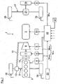
- Fig. 1 is shown in a schematic representation of the drive system of a hybrid vehicle, which is provided with an all-wheel drive unit 1.
- an internal combustion engine 5 and an electric machine 7 are connected in a drive train and connected to the transmission 9 in connection.
- the transmission 9 is connected via a Geretesgengswelle 11 and an only indicated axle differential 13 in driving connection with the vehicle wheels of the front axle 3.
- a coupling element 15 is connected, which is open or closed depending on the driving situation.
- a further electric machine 19 is arranged, which drives the two rear vehicle wheels via an axle differential 21.
- a central electronic control device 25 For the control of the drive units 5, 7, 19, a central electronic control device 25 is provided.
- the control device 25 detects the driver's request in the Fig. 1 by way of example by means of a pedal module 23, a change made by the driver side of the accelerator pedal angle.
- the control device 25 detects as input parameters, inter alia, an available battery power, the efficiency maps of all drive units 5, 7, 19, ambient or aggregate temperatures, vehicle dynamics limits, etc., whereby an axle-related drive torque distribution is made possible.
- control device 25 calculates a differential torque ⁇ M and, as a result, a desired drive torque M VA for the front axle 3 and a desired drive torque M HA for the rear axle 17.
- the front wheels and the rear wheels are each assigned a wheel sensor 26.
- the wheel sensors 26 are each signal technology in connection with the electronic control device 25 for implementation an ABS or EPS regulation.
- the electronic control device 25 is technically linked to a unit 27 for determining the coefficient of friction of the roadway.
- the torque distribution made by the control device 25 takes place as a function of input parameters known per se and taking into account parameters of a driver assistance control, which is not shown here in detail.
- the electronic control device 25 an axle-related torque distribution is possible.
- the generated in the electronic control device 25 target torque M VA , M HA for the front and rear axles 3, 17 are independently directed to the front axle 3 and the rear axle 17, respectively.
- the control device 25 To determine the coefficient of friction in the unit 27, the control device 25 must drive the rear axle 17 with drive torque M VA and M HA of different sizes.
- the torque difference ⁇ M from the different sized front and rear axle torque M VA and M HA is according to the Fig. 2 directed to the unit 27.
- the resulting speed difference ⁇ n between the front wheels and the rear wheels is also directed to the unit 27.
- the speed difference ⁇ n is also determined in the electronic control device 25 by means of the wheel sensors 26.
- a high friction coefficient ⁇ 2 is estimated based on the detected torque difference.
- a high frictional value ⁇ 2 results approximately on asphalt, while a mean frictional value ⁇ 1 occurs with snow and a low frictional value ⁇ 0 with ice.
- the coefficient of friction estimated in the unit 27 is shown in FIG Fig. 2 directed to a recuperation manager 31.
- the recuperation manager 31 determines, as a function of the detected coefficient of friction, a maximum recuperative torque M R, max which the electric machine 19 can set down on the road during recuperation without too much brake slip on the rear axle 17, resulting in unstable driving behavior results.
- the size of the Rekuperationsmoments M R, max is dependent on whether a low coefficient of friction ⁇ 0 , a Hochreibwert ⁇ 2 or a Mittelreibwert ⁇ 1 has been estimated.
- the maximum recuperation torque M R, max that can be set off on the road is correspondingly reduced in the recuperation manager 31.
- the recuperation manager 31 can increase the maximum possible recuperation torque M R, max to maximize the possible recuperation power.
- the map 29 is shown as a torque difference-speed difference diagram.
- friction coefficient fields 33, 34, 35 are entered, each of which corresponds to a low-friction value ⁇ 0 , a mean-friction ⁇ 1 and a high-friction ⁇ 2 .
- a value pair W 1 consisting of the torque difference ⁇ M 1 and a resulting speed difference ⁇ n 1 is read into the unit 27.
- Exemplary lies in the Fig. 3 a moment difference ⁇ M 1 at 50Nm and the resulting speed difference ⁇ n 1 at -3%.
- the value pair W 1 from ⁇ M 1 and ⁇ n 1 can be represented as a point of intersection in the characteristic field 29, which lies in the mean friction value field 34. Consequently, from the diagram 29 results in a mean frictional value, as it sets with snow-covered road.
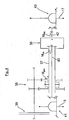
- the drive system according to a second embodiment is shown.
- the drive torque distribution is not based on an electronic control device 25, but rather by means of a mechanical Eisenachsdifferenzials 36.
- the Swissachsdifferenzial 36 is designed as a hollow shaft 37 drive shaft with a transmission output of a speed change gear 38 in combination.
- the transmission 38 is connected in a conventional manner via a separating clutch with a drive unit.
- the interaxle differential is drivingly connected via an output shaft 40 to a front differential 41 which drives front wheels (not shown).
- the insectsdifferenzial 36 is connected via a drive shaft 42 with a rear differential 43, with the rear wheels are driven.
- the drive torque distribution influencing clutch is provided.
- Differential torque .DELTA.M be set.
- the differential torque .DELTA.M can be particularly easily calculated from the transmission output torque M tot and the respectively set clutch torque of the clutch integrated in the interaxle differential 36.
Landscapes
- Engineering & Computer Science (AREA)
- Transportation (AREA)
- Mechanical Engineering (AREA)
- Chemical & Material Sciences (AREA)
- Combustion & Propulsion (AREA)
- Automation & Control Theory (AREA)
- Physics & Mathematics (AREA)
- Mathematical Physics (AREA)
- Arrangement And Driving Of Transmission Devices (AREA)
Description
- Die Erfindung betrifft ein Fahrzeug mit einem Allradantrieb nach dem Oberbegriff des Patentanspruches 1.
- Das Dokument
WO 2004/039621 A1 offenbart den Oberbegriff des Anspruchs 1. - Bei Fahrzeugen mit einem Hybridantriebssystem, bestehend aus einer Brennkraftmaschine und einer Elektromaschine, kann die Elektromaschine in einem Rekuperationsbetrieb die kinetische Energie des Fahrzeuges unter gleichzeitiger Beaufschlagung eines Rekuperations- oder Schleppmoments auf die Fahrzeugräder elektrische Energie induzieren. Bei einem Fahrzeug mit Allradantriebssystem können daher nicht nur das Antriebsmoment, sondern auch konzeptabhängige Anteile des Schleppmomentes auf die Vorderachse und/oder auf die Hinterachse abgesetzt werden. Diese Schleppmomente können insbesondere bei einem Straßenbelag mit Niedrigreibbwert zu einem hohen Bremsschlupf führen. Dies resultiert wiederum in einer Absenkung der Seitenführungskraft und dadurch in einem instabilen Fahrverhalten.
- Aus der
DE 103 04 813 A1 ist ein gattungsgemäßes Fahrzeug mit einem Allradantriebssystem bekannt. Das Antriebssystem weist ein Zwischenachsdifferenzial auf, das das Antriebsmoment auf ein Vorderachsdifferenzial und ein Hinterachsdifferenzial verteilt, über die die Vorderräder und die Hinterräder angetrieben werden. Das Zwischenachsdifferenzial weist eine die Antriebsmomentenverteilung beeinflussende Kupplung auf. Diese ist abhängig von Betriebsparametern des Fahrzeugs zur variablen Verteilung der Antriebsmomente ansteuerbar. - Die Vorder- und Hinterachsgetriebe sind in der
DE 103 04 813 A1 unterschiedlich übersetzt. Diese unterschiedlich übersetzten Achsgetriebe ergeben bei der Betätigung der Kupplung mit einem Differenzmoment eine Differenzzahl zwischen den Achsen. Das Differenzmoment kann in Abweichung zurDE 103 04 813 A1 sowie zur Erfindung gegebenenfalls auch ohne Einsatz einer solchen Kupplung bzw. unterschiedlicher Achsübersetzungen dargestellt werden. - Zur Durchführung einer ESP-Regelung oder einer ABS-Regelung weisen moderne Fahrzeuge zudem bereits serienmäßig Radsensoren auf, die die Raddrehzahlen der Vorderräder und Hinterräder im Fahrbetrieb erfassen. Da jedoch der jeweils aktuelle Straßenreibwert und das maximal auf die Straße absetzbare Rekuperationsmoment nicht bekannt sind, muss die Rekuperationsleistung des Hybridantriebes und damit der mögliche Effizienzvorteil in jeder Fahrsituation so begrenzt werden, dass ein instabiles Fahrverhalten verhindert ist. Dadurch wird jedoch auch zwangsläufig die im Bordnetz speicherbare, während des Rekuperationsbetriebes gewonnene elektrische Energie begrenzt.
- Die Aufgabe der Erfindung besteht darin, ein Fahrzeug bereitzustellen, mit dem eine einfache Ermittlung des Straßenreibwertes ermöglicht ist.
- Die Aufgabe ist durch die Merkmale des Patentanspruches 1 gelöst. Bevorzugte Weiterbildungen sind in den Unteransprüchen offenbart.
- Die Erfindung geht von dem Sachverhalt aus, dass sich bei einer Momentendifferenz zwischen der Vorderachse und der Hinterachse jeweils unterschiedlich große vorderachsseitige und hinterachsseitige Drehzahlen ergeben. Unter vorder- und hinterachsseitigen Drehzahlen in der Erfindung werden etwa die Drehzahlen der Vorder- und Hinterräder des Fahrzeuges verstanden. Alternativ sind auch die Drehzahlen der von einem Zwischenachsdifferenzial zu einem vorderen und einem hinteren Achsdifferenzial geführten Abtriebswellen zu verstehen.
- Die Drehzahldifferenzen zwischen Vorder- und Hinterachse sowie die jeweils zugehörigen Momentendiffererizen ergeben Wertepaare. Anhand von Untersuchungen konnte festgestellt werden, dass bei Straßenbelägen mit an sich unbekannten Oberflächeneigenschaften aus den oben erwähnten Wertepaaren Rückschlüsse auf den aktuellen Reibwert der Straße geführt werden können. Die Erfindung beruht demzufolge auf der Erkenntnis, dass sich bei Straßenbelägen mit unterschiedlichen Reibwerten sowie bei konstanter Momentendifferenz unterschiedlich stark ausgeprägte Drehzahldifferenzen zwischen den vorder- und hinterachsseitigen Drehzahlen ergeben. Gemäß dem kennzeichnenden Teil des Patentanspruches 1 weist nunmehr das Fahrzeug eine Einheit zur Ermittlung eines Straßenreibwertes auf, die die Drehzahldifferenz zwischen der vorder- und hinterachsseitigen Drehzahl erfasst. Die Einheit ist so ausgelegt, dass auf der Grundlage der erfassten Drehzahldifferenz sowie der zugehörigen Momentendifferenz zwischen dem Vorder- und Hinterachsantriebsmoment der Straßenreibwert ermittelbar ist. Der so ermittelte Reibwert kann als zusätzlicher Parameter bei unterschiedlichen Regelvorgängen berücksichtigt werden. Dabei ist bereits eine grobe Abschätzung, ob die Fahrbahn einen Niedrigreibwert, einen mittleren Reibwert oder einen Hochreibwert aufweist, bedeutsam zur Steigerung der Güte von Regelvorgängen.
- Die sich tatsächlich zwischen der Vorder- und Hinterachse ergebende Ist-Momentendifferenz ist nur mit sensortechnisch großem Aufwand erfassbar. Die oben genannte Einheit ermittelt daher den Reibwert nicht auf der Grundlage der Ist-Momentendifferenz, sondern einer vorgegebenen Soll-Momentendifferenz sowie der sich ergebenden Ist-Drehzahldifferenz, die problemlos etwa durch Raddrehzahlsensoren erfassbar ist.
- Zur Ermittlung des Reibwertes kann in der erfindungsgemäßen Einheit ein Kennfeld tabellarisch hinterlegt sein, aus dem anhand des Wertepaars, bestehend aus der eingestellten Momentendifferenz zwischen Vorder- und Hinterachsantriebsmoment und der erfassten Drehzahldifferenz, der Reibwert des Straßenbelags abschätzbar ist. Wie oben erwähnt genügt bereits eine grobe Einteilung in Hochreibwert, mittlerem Reibwert oder Niedrigreibwert.
- Das oben erwähnte Kennfeld kann empirisch aus Versuchen ermittelt werden, und zwar bei anhand von Straßenbelägen mit jeweils bekannten Hoch-, Mittel- oder Niedrigreibwert sowie mit vordefinierten, beispielsweise aus Reifen-Kennfelder gewonnenen unterschiedlichen Momentendifferenzen und Drehzahldifferenzen. Die Wertepaare aus Momentendifferenzen und zugehörigen Drehzahldifferenzen werden in das Kennfeld eingetragen. Daraus ergeben sich im Kennfeld für den jeweils vorbekannten Hoch-, Mittel- und Niedrigreibwert Wertepaar-Gruppen, die im Kennfeld örtlich unterschiedlich liegen. Durch Extrapolieren kann jede der Hochreibwert-, Mittelreibwert- und Niedrigreibwert-Gruppen als ein Reibwert-Feld im Kennfeld dargestellt werden.
- Das in der oben erwähnten Versuchs-Betriebsart ermittelte Kennfeld kann im normalen Fahrbetrieb der Reibwert-Ermittlung zugrunde gelegt werden. In diesem Fall wird ein Wertepaar aus Momentendifferenz und Drehzahldifferenz erfasst. Das Wertepaar wird in das Kennfeld als Schnittpunkt eingetragen, der sich entweder im Hochreibwert-Feld, im Niedrigreibwert-Feld oder im Mittelreibwert-Feld wiederfindet.
- Alternativ oder zusätzlich dazu kann auf der Grundlage von Reifenkennfeldern und von analytischen Zusammenhängen der Reibwert ausgehend von Momentendifferenzen sowie Drehzahldifferenzen berechnet werden. Bei der Berechnung bzw. bei der empirischen Bestimmung des Kennfeldes können darüberhinaus Streuungen, Ungenauigkeiten des Systems und Änderungen von Fahrzeug- und Reifendaten berücksichtigt werden. Auf diese Weise erhält man als Kennfeld ein Differenzmoment-Differenzdrehzahl-Diagramm.
- Wie oben bereits angedeutet, kann das so generierte Kennfeld in einem Fahrbetrieb wie folgt abgeschätzt werden: Zunächst wird die sich auf das Differenzmoment einstellende Drehzahldifferenz erfasst. Diese beiden IstWerte werden in das in der Einheit hinterlegte Kennfeld eingetragen. Je nach Straßenbelag liegt das Wertepaar aus dem Differenzmoment und der sich einstellenden Ist-Drehzahldifferenz in dem Hochreibwertfeld, dem Mittelreibwertfeld oder dem Niedrigreibwertfeld. Damit kann abgeschätzt werden, ob sich das Fahrzeug mit dem Wertepaar auf einer Fahrbahn mit Hoch-, Mittel- oder Niedrigreibwert bewegt.
- Erfindungsgemäß ist die Drehzahldifferenz zwischen einer vorder- und hinterachsseitigen Drehzahl zur Ermittlung des Reibwertes heranzuziehen. Zur besonders einfachen Erfassung der Drehzahldifferenz können bevorzugt Radsensorelemente eingesetzt werden, die ohnehin im Fahrzeug verbaut sind, um eine ABS- oder eine ESP-Regelung zu ermöglichen. Entsprechend sind bei dieser Ausführungsform keine zusätzlichen Sensorelemente zur Bestimmung der Drehzahldifferenz erforderlich.
- Das Allradantriebssystem des Fahrzeuges kann eine Momentenverteilungseinheit aufweisen, mit der auf eine Vorgabe eine Antriebsmomentenverteilung des Antriebsmomentes auf die Vorderachse und auf die Hinterachse einstellbar und/oder änderbar ist. Um eine Reibwertermittlung zu ermöglichen, ist jedoch dafür Sorge zu tragen, dass zumindest bei der Erfassung der Ist-Drehzahldifferenz eine Momentendifferenz zwischen den Achsen eingestellt ist.
- Die Momentenverteilungseinheit kann in einer Ausführungsvariante eine elektronische Berechnungseinheit sein, die aufgrund der Grundlage unterschiedlicher Betriebsparameter einen Vorderachsantrieb sowie einen Hinterachsantrieb so ansteuert, dass sich das vorgegebene Gesamt-Antriebsmoment ergibt. Alternativ dazu kann die Momentenverteilungseinheit als ein Zwischenachsdifferenzial ausgebildet sein, das das Antriebsmoment auf ein Vorderachsdifferenzial und ein Hinterachsdifferenzial aufteilt. Über die Vorder- und Hinterachsdifferen ziale werden wiederum die Vorder- und Hinterräder angetrieben. In diesem Fall kann das Zwischenachsdifferenzial beispielsweise eine, die Abtriebsmomentenverteilung beeinflussende Kupplung aufweisen. Die Kupplung kann abhängig von den Betriebsparametern des Fahrzeugs zur variablen Verteilung der Antriebsmomente angesteuert werden und führt bei Aktivierung zu einer Differenzdrehzahl.
- Bei einem derart gestalteten Antriebssystem kann von einem Getriebeausgangsmoment, das in das Zwischenachsdifferenzial geleitet wird, und dem Kupplungsmoment der im Zwischenachsdifferenzial integrierten Kupplung in einfacher Weise auf das Differenzmoment geschlossen werden.
- Die erfindungsgemäße Schätzung des Reibwertes ist insbesondere im Hinblick auf eine Steigerung der Rekuperationsleistung einer im Antriebssystem eingesetzten Elektromaschine von Vorteil. Bekanntermaßen kann die Elektromaschine nicht nur als Motor, sondern auch als Generator eingesetzt werden, der in einem Rekuperationsbetrieb unter Ausübung eines Rekuperationsmomentes auf die Fahrzeugräder der Vorder- und/oder Hinterachse elektrische Energie induziert, die im Bordnetz gespeichert wird. Das Rekuperationsbeziehungsweise Schleppmoment kann insbesondere bei Straßenbelägen mit Niedrigreibwert zu einem hohen Bremsschlupf führen, wodurch eine Seitenführungskraft reduziert wird und sich daraus ein instabiles Fahrverhalten ergeben kann. Da in herkömmlichen Fahrzeugen keine Informationen über den aktuellen Reibwert vorliegen, ist der maximal mögliche Rekuperationsmoment aus Sicherheitsgründen auf einen Grenzwert beschränkt, der auch unter ungünstigen Fahrbedingungen nicht zu einem instabilen Fahrverhalten führt.
- Erfindungsgemäß ist dagegen das maximal mögliche Rekuperationsmoment nicht auf einen Grenzwert festgelegt, sondern kann das maximal auf die Straße absetzbare Rekuperationsmoment in Abhängigkeit von dem aktuellen Straßenreibwert variiert werden. Das heißt, dass bei einer Fahrbahn mit Hochreibwert das maximal mögliche Rekuperationsmoment angehoben wird, da kein zu hoher Bremsschlupf zu befürchten ist. Dadurch kann insbesondere bei einer Fahrbahn mit Hochreibwert im Vergleich zum Stand der Technik eine zusätzliche Rekuperationsleistung generiert werden. Gleichzeitig ist die Fahrzeugstabilität unabhängig vom jeweils aktuellen Reibwert sichergestellt.
- Zur Durchführung einer Fahrzeugverzögerung wird erfindungsgemäß von einer elektronischen Steuereinrichtung unter Berücksichtigung des maximal möglichen Rekuperationsmoments ein Bremsmoment ermittelt, mit dem die Fahrzeugradbremsen beaufschlagt werden müssen, um dem Fahrerwunsch zu folgen. Das maximal mögliche Rekuperationsmoment wird von der elektronischen Steuereinrichtung in Abhängigkeit von dem eingeschätzten Reibwert festgelegt.
- Nachfolgend sind zwei Ausführungsbeispiele der Erfindung anhand der beigefügten Figuren beschrieben.
- Es zeigen:
- Fig. 1
- in einer schematischen Ansicht ein Antriebssystem eines Kraftfahrzeugs gemäß dem ersten Ausführungsbeispiel;
- Fig. 2
- ein Blockschaltdiagramm, anhand dem die Einstellung des maximal möglichen Rekuperationsmomentes der Elektromaschine für den Hinterachsantrieb veranschaulicht ist;
- Fig. 3
- das Kennfeld, das in der Einheit zur Ermittlung des Straßenreibwertes hinterlegt ist; und
- Fig. 4
- in einer schematischen Darstellung ein Antriebssystem eines Kraftfahrzeugs gemäß dem zweiten Ausführungsbeispiel.
- In der
Fig. 1 ist in einer Prinzipdarstellung das Antriebssystem eines Hybridfahrzeuges gezeigt, das mit einer Allradantriebseinheit 1 versehen ist. An der vorderen Fahrzeugachse 3 ist eine Brennkraftmaschine 5 sowie eine Elektromaschine 7 in einen Antriebsstrang geschaltet und mit dem Getriebe 9 in Verbindung. Das Getriebe 9 ist über eine Getriebeausgengswelle 11 sowie ein nur angedeutetes Achsdifferenzial 13 in trieblicher Verbindung mit den Fahrzeugrädern der Vorderachse 3. Zwischen der Brennkraftmaschine 5 und der Elektromaschine 7 ist ein Kupplungselement 15 geschaltet, das je nach Fahrsituation geöffnet oder geschlossen ist. - An der Hinterachse 17 des Kraftfahrzeuges ist eine weitere Elektromaschine 19 angeordnet, die die beiden hinteren Fahrzeugräder über ein Achsdifferenzial 21 antreibt.
- Soweit es für das Verständnis der Erfindung erforderlich ist, sind in der
Fig. 1 der Vorderachsantrieb und der aus der Elektromaschine 19 bestehende Hinterachsantrieb skizziert. Weitere Antriebskomponenten, etwa die Hochvoltbatterie 2 zur Stromversorgung der beiden Elektromaschinen 7, 19 oder etwa das Motorsteuergerät 4, das Getriebesteuergerät 6, die Leistungselektronik 8 der beiden Elektromaschinen 7, 19 oder das Batteriesteuergerät 10, sind ohne nähere Beschreibung nur grob angedeutet. - Für die Ansteuerung der Antriebsaggregate 5, 7, 19 ist eine zentrale elektronische Steuereinrichtung 25 vorgesehen. Die Steuereinrichtung 25 erfasst den Fahrerwunsch in der
Fig. 1 beispielhaft mittels eines Pedalmoduls 23 eine fahrerseitig vorgenommene Änderung des Fahrpedalwinkels. Zusätzlich erfasst die Steuereinrichtung 25 als Eingangsparameter unter anderem eine verfügbare Batterieleistung, die Wirkungsgradkennfelder sämtlicher Antriebsaggregate 5, 7, 19, Umgebungs- beziehungsweise Aggregate-Temperaturen, Fahrdynamikgrenzen, etc., wodurch eine achsbezogene Antriebsmomentenverteilung ermöglicht ist. - Auf der Grundlage dieser Eingangsgrößen berechnet die Steuereinrichtung 25 ein Differenzmoment ΔM und sich daraus ergebend ein Soll-Antriebsmoment MVA für die Vorderachse 3und ein Soll-Antriebsmoment MHA für die Hinterachse 17.
- Gemäß der
Fig. 1 ist der Vorderräder und der Hinterräder jeweils ein Radsensor 26 zugeordnet. Die Radsensoren 26 sind jeweils signaltechnisch in Verbindung mit der elektronischen Steuereinrichtung 25 zur Durchführung einer ABS- oder EPS-Regelung. Zudem ist die elektronische Steuereinrichtung 25 signaltechnisch verknüpft mit einer Einheit 27 zur Ermittlung des Reibwertes der Fahrbahn. - Die von der Steuereinrichtung 25 vorgenommene Momentenverteilung erfolgt in Abhängigkeit von an sich bekannten Eingangsparametern sowie unter Berücksichtigung von Parametern einer Fahrerassistenzregelung, die hier nicht näher gezeigt ist. Durch die elektronische Steuereinrichtung 25 ist eine achsbezogene Momentenverteilung ermöglicht. Die in der elektronischen Steuereinrichtung 25 generierten Sollmomente MVA, MHA für die Vorder- und Hinterachsen 3, 17 werden voneinander unabhängig jeweils zur Vorderachse 3 und zur Hinterachse 17 geleitet.
- Zur Ermittlung des Reibwertes in der Einheit 27 muss die Steuereinrichtung 25 die Hinterachse 17 mit unterschiedlich großen Antriebsmomenten MVA und MHA antreiben. Die Momentendifferenz ΔM aus den unterschiedlich großen Vorder- und Hinterachsmomenten MVA und MHA wird gemäß der
Fig. 2 an die Einheit 27 geleitet. Zusätzlich wird auch die sich ergebende Drehzahldifferenz Δn zwischen den Vorderrädern und den Hinterrädern zur Einheit 27 geleitet. Die Drehzahldifferenz Δn wird mithilfe der Radsensoren 26 ebenfalls in der elektronischen Steuereinrichtung 25 ermittelt. - In der Einheit 27 ist ein in der
Fig. 2 nur angedeutetes Kennfeld 29 hinterlegt, das später anhand derFig. 3 näher beschrieben ist. Aus dem Kennfeld 29 wird anhand der erfassten Momentendifferenz ΔM und der erfassten Drehzahldifferenz Δn abgeschätzt, ob die Fahrbahn einen Niedrigreibwert µ0, einen Mittelreibwert p1 oder einen Hochreibwert µ2 aufweist. Ein Hochreibwert µ2 ergibt sich etwa auf Asphalt, während ein Mittelreibwert µ1 sich bei Schnee und ein Niedrigreibwert µ0 sich bei Eis einstellt. - Der in der Einheit 27 abgeschätzte Reibwert wird in der
Fig. 2 zu einem Rekuperationsmanager 31 geleitet. Der Rekuperationsmanager 31 bestimmt in Abhängigkeit von dem erfassten Reibwert ein maximal auf die Straße absetzbares Rekuperationsmoment MR,max, das die Elektromaschine 19 im Rekuperationsbetrieb auf die Straße absetzen kann, ohne dass sich an der Hinterachse 17 ein zu hoher Bremsschlupf mit daraus resultierendem instabilen Fahrverhalten ergibt. Die Größe des Rekuperationsmoments MR,max ist dabei abhängig davon, ob ein Niedrigreibwert µ0, ein Hochreibwert µ2 oder ein Mittelreibwert µ1 abgeschätzt worden ist. Um bei einem abgeschätzten Niedrigreibwert µ0 einen zu hohen Bremsschlupf beim Rekuperationsbetrieb zu vermeiden, wird das maximal auf die Straße absetzbare Rekuperationsmoment MR,max im Rekuperationsmanager 31 entsprechend reduziert. Im Gegenzug kann bei Abschätzung eines Hochreibwertes µ1 der Rekuperationsmanager 31 das maximal mögliche Rekuperationsmoment MR,max hochsetzen, um die mögliche Rekuperationsleistung zu maximieren. - In der
Fig. 3 ist das Kennfeld 29 als ein Momentendifferenz-Drehzahldifferenz-Diagramm dargestellt. In dem Diagramm 29 sind jeweils Reibwert-Felder 33, 34, 35 eingetragen, die jeweils einem Niedrigreibwert µ0, einen Mittelreibwert µ1 und einem Hochreibwert µ2 entsprechen. Zur Bestimmung des aktuellen Reibwertes wird in derFig. 3 zunächst ein Wertepaar W1, bestehend aus der Momentendifferenz ΔM1 und einer sich daraus ergebenden Drehzahldifferenz Δn1 in die Einheit 27 eingelesen. Beispielhaft liegt in derFig. 3 eine Momentendifferenz ΔM1 bei 50Nm und die sich daraus ergebende Drehzahldifferenz Δn1 bei -3%. Das Wertepaar W1 aus ΔM1 und Δn1 ist als Schnittpunkt im Kennfeld 29 darstellbar, der im Mittelreibwert-Feld 34 liegt. Folglich ergibt sich aus dem Diagramm 29 ein Mittelreibwert, wie er sich bei schneebedeckter Fahrbahn einstellt. - Das in der
Fig. 2 gezeigte Diagramm 29 mit den unterschiedlichen Reibwert-Feldern 33, 34, 35 wird in empirisch durchgeführten Versuchen ermittelt, und zwar bei Straßenbelägen mit vordefiniertem Hochreibwert µ2, mit vordefiniertem Mittelreibwert µ1 und mit vordefiniertem Niedrigreibwert µ0. Bei derart bekannten Reibwerten werden unterschiedlich große Momentendifferenzen ΔM auf die Vorder- und Hinterachse 3, 17 aufgeprägt. Die sich dadurch ergebenden Wertepaare W werden in das Kennfeld 29 als Punkte eingetragen. - Dadurch ergibt sich eine Vielzahl von in der
Fig. 3 gezeigten Wertepaar-Punkten W, die jeweils einem bekannten Niedrig-, Hoch- oder Mittelreibwert µ0, µ1, µ2 zugeordnet sind. Daraus können in einem nächsten Schritt die Reibwert-Felder 33, 34, 35 im Diagramm 29 extrapoliert werden. - In der
Fig. 4 ist das Antriebssystem gemäß einem zweiten Ausführungsbeispiel gezeigt. In diesem Fall erfolgt die Antriebsmomentenverteilung nicht auf der Grundlage einer elektronischen Steuereinrichtung 25, sondern vielmehr mithilfe eines mechanischen Zwischenachsdifferenzials 36. Das Zwischenachsdifferenzial 36 ist eine als Hohlwelle 37 ausgeführte Antriebswelle mit einem Getriebeausgang eines Geschwindigkeits-Wechselgetriebes 38 in Verbindung. Das Getriebe 38 ist in an sich bekannter Weise über eine Trennkupplung mit einem Antriebsaggregat verbunden. Das Zwischenachsdifferenzial über eine Abtriebswelle 40 mit einem Vorderachsdifferenzial 41 trieblich verbunden, das nicht dargestellte Vorderräder antreibt. Zudem ist das Zwischenachsdifferenzial 36 ist über eine Antriebswelle 42 mit einem Hinterachsdifferenzial 43 verbunden, mit dem Hinterräder antreibbar sind. - In dem Zwischenachsdifferenzial 36 ist eine nicht näher gezeigte, die Antriebsmomentenverteilung beeinflussende Kupplung vorgesehen. In
- Differenzmoment ΔM eingestellt werden. Bei einem solchen Antriebssystem kann das Differenzmoment ΔM besonders einfach aus dem Getriebeausgangsmoment Mges und dem jeweils eingestellten Kupplungsmoment der im Zwischenachsdifferenzial 36 integrierten Kupplung berechnet werden.
Claims (7)
- Fahrzeug mit einem Allradantriebssystem, bei dem die Vorderachse (3) und die Hinterachse (17) des Fahrzeugs mit unterschiedlich großen Vorderachs- und Hinterachsmomenten (MVA, MHA) antreibbar sind, wobei sich aus einer Momentendifferenz (ΔM1) zwischen den Vorderachs- und Hinterachsmomenten (MVA, MHA) eine Drehzahldifferenz (Δn1) zwischen einer vorderachsseitigen Drehzahl (nVA) und einer hinterachsseitigen Drehzahl (nHA) ergibt, wobei das Fahrzeug eine Einheit (27) zur Ermittlung eines Straßenreibwertes (µ0, µ1, µ2) aufweist, die die Drehzahldifferenz (Δn1) erfasst, und die Einheit (27) auf der Grundlage eines aus der Drehzahldifferenz (Δn1) und der Momentendifferenz (ΔM1)oder damit korrelierenden Parameter bestehenden Wertepaars (W1) den Straßenreibwert (µ0, µ1, µ2) ermittelt und das Antriebsmoment des Fahrzeugs von zumindest einer Elektromaschine (19) erzeugbar ist, die in einem Rekuperationsbetrieb unter Ausübung eines Rekuperationsmoments (MR) auf die Fahrzeugräder der Vorderachse (3) und/oder der Hinterachse (17) eine elektrische Spannung induziert, dadurch gekennzeichnet, dass der Elektromaschine (19) ein Rekuperationsmanager (31) zugeordnet ist, der das auf die Fahrzeugräder der Vorderachse (3) und der Hinterachse (17) ausübbare Rekuperationsmoment (MR) auf einen oberen Grenzwert, dass heißt ein maximal mögliches Rekuperationsmoment (MR,max), begrenzt, und dass das Grenzmoment (MR,max) und/oder die Verteilung des Rekuperationsmoments (MR) auf die Vorderachse (3) und die Hinterachse (17) in Abhängigkeit vom ermittelten Reibwert (µ0, µ1, µ2) variierbar ist.
- Fahrzeug nach Anspruch 1, dadurch gekennzeichnet, dass in der Einheit (27) ein Kennfeld (29) hinterlegt ist, aus dem anhand der eingestellten Momentendifferenz (ΔM1) und der erfassten Drehzahldifferenz (Δn1) der Reibwert (µ0, µ1, µ2) der Straße abschätzbar ist.
- Fahrzeug nach Anspruch 2, dadurch gekennzeichnet, dass die Generierung des Kennfeldes (29) bei Straßen mit jeweils bekanntem Reibwert (µ0, µ1, µ2) erfolgt, und dass unter Vorgabe unterschiedlicher Momentendifferenzen (ΔM) die sich jeweils ergebenden Drehzahldifferenzen (Δn) erfassbar sind, wobei die sich aus den Momentendifferenzen (ΔM) und den Drehzahldifferenzen (Δn) ergebenden Wertepaare (W) in das Kennfeld (29) eintragbar sind.
- Fahrzeug nach einem der vorhergehenden Ansprüche, dadurch gekennzeichnet, dass jedem der Fahrzeugräder an der Vorderachse (3) und an der Hinterachse (17) je ein Radsensor (26) zugeordnet ist, die zur Erfassung der Drehzahldifferenz (Δn1) auch bei der ReibwertErmittlung einsetzbar sind:
- Fahrzeug nach einem der vorhergehenden Ansprüche, dadurch gekennzeichnet, dass das Antriebssystem des Fahrzeugs eine Momentenverteilungseinheit (25, 36) aufweist, mit der auf eine fahrerseitige Vorgabe eine Momentenverteilung des Antriebsmoments (Mges) auf die Vorderachse (3) und die Hinterachse (17) einstellbar ist, wobei zur Reibwert-Ermittlung die Momentenverteilungseinheit (25, 36) eine ungleichmäßige Momentenverteilung mit sich einstellender Momentendifferenz (ΔM1) festlegt.
- Fahrzeug nach einem der vorhergehenden Ansprüche, dadurch gekennzeichnet, dass zur Durchführung einer Fahrzeugverzögerung eine elektronische Steuereinrichtung (25) des Fahrzeugs unter Berücksichtigung des maximal möglichen Rekuperationsmoments (MR,Max) ein Bremsmoment ermittelt, mit dem die Fahrzeugradbremsen beaufschlagbar sind.
- Fahrzeug nach einem der vorergehenden Ansprüche, dadurch gekennzeichnet, dass die Momentenverteilungseinheit (36) ein Zwischenachsdifferenzial ausgebildet ist, das das Antriebsmoment auf ein Vorderachs- und ein Hinterachsdifferenzial (41, 43) verteilt, über die die Vorder- und Hinterräder antreibbar sind, wobei das Zwischenachsdifferenzial (36) eine die Abtriebsmomentenverteilung beeinflussende Kupplung aufweist, die abhängig von Betriebsparametern des Fahrzeugs zur variablen Verteilung der Antriebsmomente ansteuerbar ist.
Applications Claiming Priority (2)
| Application Number | Priority Date | Filing Date | Title |
|---|---|---|---|
| DE102010047443A DE102010047443A1 (de) | 2010-10-04 | 2010-10-04 | Kraftfahrzeug mit einem Allradantrieb |
| PCT/EP2011/004542 WO2012045386A1 (de) | 2010-10-04 | 2011-09-09 | Kraftfahrzeug mit einem allradantrieb |
Publications (2)
| Publication Number | Publication Date |
|---|---|
| EP2625054A1 EP2625054A1 (de) | 2013-08-14 |
| EP2625054B1 true EP2625054B1 (de) | 2016-07-20 |
Family
ID=44651635
Family Applications (1)
| Application Number | Title | Priority Date | Filing Date |
|---|---|---|---|
| EP11757174.5A Not-in-force EP2625054B1 (de) | 2010-10-04 | 2011-09-09 | Kraftfahrzeug mit einem allradantrieb |
Country Status (5)
| Country | Link |
|---|---|
| US (1) | US8649929B2 (de) |
| EP (1) | EP2625054B1 (de) |
| CN (1) | CN103153675B (de) |
| DE (1) | DE102010047443A1 (de) |
| WO (1) | WO2012045386A1 (de) |
Families Citing this family (16)
| Publication number | Priority date | Publication date | Assignee | Title |
|---|---|---|---|---|
| DE102012020906A1 (de) | 2012-10-24 | 2014-04-24 | Audi Ag | Verfahren und System zum Betreiben eines Antriebsstrangs eines Kraftwagens |
| DE102013226611A1 (de) * | 2013-12-19 | 2015-06-25 | Robert Bosch Gmbh | Verfahren zum Betreiben einer Hybridantriebsvorrichtung |
| DE102013226997A1 (de) * | 2013-12-20 | 2015-06-25 | Robert Bosch Gmbh | Vorrichtung und Verfahren zur Ermittlung einer den Reibwert einer von einem Kraftfahrzeug befahrenen Fahrbahn repräsentierenden Reibwertgröße |
| DE102014007090B3 (de) | 2014-05-15 | 2015-09-10 | Audi Ag | Verfahren zum Betreiben eines Antriebsstrangs für ein Kraftfahrzeug sowie entsprechender Antriebsstrang |
| DE102016214421A1 (de) * | 2016-08-04 | 2018-02-08 | Audi Ag | Verfahren zum Betreiben einer Kupplung eines Kraftfahrzeugs, sowie Kraftfahrzeug |
| DE102016013260B4 (de) | 2016-11-09 | 2020-07-23 | Carl Zeiss Smt Gmbh | Verfahren zur Erzeugung eines Referenzbildes bei der Charakterisierung einer Maske für die Mikrolithographie |
| DE102016223186A1 (de) * | 2016-11-23 | 2018-05-24 | Audi Ag | Allradsystem für ein Kraftfahrzeug und Verfahren zum Betreiben eines Allradsystems eines Kraftfahrzeugs |
| DE102017208449B4 (de) | 2017-05-18 | 2019-03-14 | Audi Ag | Allradantrieb für ein Kraftfahrzeug |
| DE102018203354A1 (de) * | 2018-03-07 | 2019-09-12 | Robert Bosch Gmbh | Verfahren zum Betrieb eines Fahrerassistenzsystems in einem Kraftfahrzeug |
| DE102018207007A1 (de) * | 2018-05-07 | 2019-11-07 | Audi Ag | Flüssigkeitsgekühltes elektrisches Antriebssystem |
| SE541907C2 (en) * | 2018-05-21 | 2020-01-07 | Scania Cv Ab | Method and control device for controlling operation of a brake system of a motor vehicle |
| DE102018220259A1 (de) * | 2018-11-26 | 2020-05-28 | Robert Bosch Gmbh | Verfahren und Steuergerät zum Betreiben eines Fahrzeugs |
| DE102018220576A1 (de) | 2018-11-29 | 2020-06-04 | Robert Bosch Gmbh | Verfahren und Steuergerät zum Bestimmen eines Reibwertpotentials eines Fahrbahnbelags |
| DE102020102193A1 (de) | 2020-01-30 | 2021-08-05 | Bayerische Motoren Werke Aktiengesellschaft | Antriebssystem für ein zumindest zeitweise straßengekoppelt allradangetriebenes Elektrofahrzeug |
| EP3943350B1 (de) * | 2020-07-21 | 2023-12-06 | KNORR-BREMSE Systeme für Nutzfahrzeuge GmbH | Vorrichtung und verfahren zur bestimmung der strassenreibung |
| DE102021214938A1 (de) | 2021-12-22 | 2023-06-22 | Robert Bosch Gesellschaft mit beschränkter Haftung | Verfahren zum Betreiben eines Fahrzeugs mit mehreren antreibenden Achsen |
Family Cites Families (20)
| Publication number | Priority date | Publication date | Assignee | Title |
|---|---|---|---|---|
| US6047231A (en) * | 1997-06-06 | 2000-04-04 | Ford Global Technologies, Inc. | Four wheel drive transfer case controller compatible with a spare tire |
| US6575870B2 (en) | 2000-07-21 | 2003-06-10 | Honda Giken Kogyo Kabushiki Kaisha | Driving force control system for front-and-rear wheel drive vehicles |
| JP3915391B2 (ja) | 2000-09-14 | 2007-05-16 | トヨタ自動車株式会社 | 車輌の制動力制御装置 |
| JP4039146B2 (ja) * | 2001-09-27 | 2008-01-30 | 日産自動車株式会社 | 制動制御装置 |
| AT6549U1 (de) | 2002-09-03 | 2003-12-29 | Magna Steyr Powertrain Ag & Co | Antriebsachse für ein kraftfahrzeug mit variabler momentenverteilung |
| SE524087C2 (sv) | 2002-10-31 | 2004-06-22 | Nira Dynamics Ab Mjaerdevi Sci | Metod för bestämning av friktionen mellan en yta och ett däck för vägfordon som drivs med alla hjul samt en transmissionskoppling för fördelning av ett vridmoment mellan hjulaxlar innefattande nämnda metod |
| DE10260196A1 (de) * | 2002-12-20 | 2004-07-01 | Bayerische Motoren Werke Ag | Verfahren zum Steuern einer schaltbaren Kupplung in einem Antriebsstrang eines Kraftfahrzeugs mit Vierradantrieb |
| DE10304813A1 (de) | 2003-02-06 | 2004-08-19 | Audi Ag | Antriebsvorrichtung |
| DE102004024086A1 (de) | 2004-05-14 | 2005-12-08 | Audi Ag | Antriebsvorrichtung für Kraftfahrzeuge |
| DE102005057285B4 (de) | 2005-01-09 | 2022-10-27 | Continental Automotive Technologies GmbH | Verfahren zur Steuerung eines Bremssystems eines Kraftfahrzeugs |
| DE102005015485A1 (de) * | 2005-04-05 | 2006-11-30 | Daimlerchrysler Ag | Antriebsstrang eines Fahrzeuges und Verfahren zur Steuerung eines Antriebsstranges |
| DE102005025617B4 (de) | 2005-06-03 | 2024-01-18 | Bayerische Motoren Werke Aktiengesellschaft | Steuereinrichtung für ein Antriebssystem in einem Kraftfahrzeug mit einem variablen Allradantrieb |
| DE102006018661A1 (de) | 2006-04-21 | 2007-10-25 | Audi Ag | Differenzialgetriebe für ein Kraftfahrzeug |
| EP2144794B1 (de) | 2007-04-05 | 2013-01-02 | Continental Teves AG & Co. oHG | Verfahren zum betrieb einer fahrzeugbremsanlage sowie fahrzeugbremsanlage |
| CN101054065B (zh) * | 2007-05-25 | 2011-03-16 | 吉林大学 | 混合动力轿车再生制动与防抱死集成控制系统 |
| JP2008301564A (ja) | 2007-05-29 | 2008-12-11 | Toyota Motor Corp | 車両の回生制動制御装置及びそれを含む車両制御装置 |
| US8055424B2 (en) * | 2008-11-21 | 2011-11-08 | GM Global Technology Operations LLC | Real-time identification of maximum tire-road friction coefficient by induced wheels acceleration/deceleration |
| DE102009000044A1 (de) | 2009-01-07 | 2010-07-08 | Robert Bosch Gmbh | Verfahren und Vorrichtung zum Betreiben eines Fahrzeuges, insbesondere eines Hybridfahrzeuges |
| JP4751455B2 (ja) * | 2009-01-27 | 2011-08-17 | 本田技研工業株式会社 | 車両の駆動力制御装置 |
| JP2010241166A (ja) | 2009-04-01 | 2010-10-28 | Nissan Motor Co Ltd | 車両の四輪駆動制御装置及び四輪駆動制御方法 |
-
2010
- 2010-10-04 DE DE102010047443A patent/DE102010047443A1/de not_active Withdrawn
-
2011
- 2011-09-09 WO PCT/EP2011/004542 patent/WO2012045386A1/de not_active Ceased
- 2011-09-09 US US13/877,551 patent/US8649929B2/en not_active Expired - Fee Related
- 2011-09-09 CN CN201180048248.XA patent/CN103153675B/zh not_active Expired - Fee Related
- 2011-09-09 EP EP11757174.5A patent/EP2625054B1/de not_active Not-in-force
Also Published As
| Publication number | Publication date |
|---|---|
| EP2625054A1 (de) | 2013-08-14 |
| WO2012045386A1 (de) | 2012-04-12 |
| DE102010047443A1 (de) | 2012-04-05 |
| US20130325232A1 (en) | 2013-12-05 |
| CN103153675A (zh) | 2013-06-12 |
| CN103153675B (zh) | 2016-08-10 |
| US8649929B2 (en) | 2014-02-11 |
Similar Documents
| Publication | Publication Date | Title |
|---|---|---|
| WO2012045386A1 (de) | Kraftfahrzeug mit einem allradantrieb | |
| EP2911907B1 (de) | Verfahren und system zum betreiben eines antriebsstrangs eines kraftwagens | |
| EP3116734B1 (de) | Verfahren zur ansteuerung von e-motoren bei seriellen hybridfahrzeugen oder vollelektrischen fahrzeugen mit mindestens zwei separat angetriebenen achsen | |
| DE102006046093B4 (de) | Bremssystem und Verfahren zum Bremsen eines Fahrzeugs mit einem Hybridantrieb | |
| EP2550171B1 (de) | Fahrzeug mit zumindest zwei einzelradantriebseinheiten | |
| EP2040962B1 (de) | Verfahren zum kompensieren der bremsverzögerung bei einer fahrzeugregelung | |
| DE102010015423A1 (de) | Antriebsvorrichtung für ein allradgetriebenes Fahrzeug | |
| EP3544849B1 (de) | Allradsystem für ein elektrisches kraftfahrzeug und verfahren zum betreiben eines allradsystems eines solchen fahrzeugs | |
| DE102008012848A1 (de) | Fahrzeugfahrtunterstützungssystem | |
| EP1989087B1 (de) | Verfahren und vorrichtung zur regelung des antriebsschlupfes angetriebener räder eines fahrzeugs mit der motordrehzahl als stellgrösse | |
| DE102012020908A1 (de) | Verfahren und System zum Betreiben eines Antriebsstrangs eines Kraftwagens | |
| WO2015074822A1 (de) | Verfahren, vorrichtung und computerprogrammprodukt zum betreiben eines antriebsstrangs eines kraftfahrzeugs | |
| DE102012222197A1 (de) | Drehmomentaufteilung bei einem insbesondere einen Allradantrieb umfassenden Kraftfahrzeug im Fall einer aktuellen oder bevorstehenden Parksituation | |
| DE102009022303A1 (de) | Verfahren zum Schutz von antriebsrelevanten Bauteilen eines Kraftfahrzeugs | |
| DE102008035556A1 (de) | Steuer- oder Regelsystem für ein zumindest zeitweise vierradgetriebenes Kraftfahrzeug | |
| DE102010015424B4 (de) | Antriebsvorrichtung für ein allradgetriebenes Fahrzeug | |
| DE102013223163A1 (de) | Verfahren zur Steuerung eines Bremssystems | |
| EP2640616B1 (de) | Fahrzeug, insbesondere hybridfahrzeug | |
| DE102009026813A1 (de) | Verfahren zur Erzeugung eines auf die Fahrzeugräder eines Fahrzeugs wirkenden Differenzmoments | |
| WO2023099081A1 (de) | Verfahren zum betreiben einer antriebsachse für ein kraftfahrzeug, steuereinheit, antriebsachse und kraftfahrzeug | |
| WO2012130356A1 (de) | Verfahren zur antriebsschlupfregelung für fahrzeuge mit einzelradantrieb | |
| DE102015010119A1 (de) | Antriebsvorrichtung für ein allradgetriebenes Kraftfahrzeug | |
| EP3088233B1 (de) | Verfahren und steuereinheit zur traktionskontrolle von angetriebenen rädern sowie landwirtschaftliche arbeitsmaschine | |
| WO2016110313A1 (de) | Verfahren zur ansteuerung von e-motoren bei seriellen hybridfahrzeugen mit mindestens zwei separat angetriebenen achsen | |
| DE102020200760A1 (de) | Verfahren zur Fahrzeugführung und elektronisches Fahrzeugführungssystem |
Legal Events
| Date | Code | Title | Description |
|---|---|---|---|
| PUAI | Public reference made under article 153(3) epc to a published international application that has entered the european phase |
Free format text: ORIGINAL CODE: 0009012 |
|
| 17P | Request for examination filed |
Effective date: 20130506 |
|
| AK | Designated contracting states |
Kind code of ref document: A1 Designated state(s): AL AT BE BG CH CY CZ DE DK EE ES FI FR GB GR HR HU IE IS IT LI LT LU LV MC MK MT NL NO PL PT RO RS SE SI SK SM TR |
|
| RIN1 | Information on inventor provided before grant (corrected) |
Inventor name: STRASSER, SEBASTIAN |
|
| DAX | Request for extension of the european patent (deleted) | ||
| GRAP | Despatch of communication of intention to grant a patent |
Free format text: ORIGINAL CODE: EPIDOSNIGR1 |
|
| INTG | Intention to grant announced |
Effective date: 20160502 |
|
| GRAS | Grant fee paid |
Free format text: ORIGINAL CODE: EPIDOSNIGR3 |
|
| GRAA | (expected) grant |
Free format text: ORIGINAL CODE: 0009210 |
|
| AK | Designated contracting states |
Kind code of ref document: B1 Designated state(s): AL AT BE BG CH CY CZ DE DK EE ES FI FR GB GR HR HU IE IS IT LI LT LU LV MC MK MT NL NO PL PT RO RS SE SI SK SM TR |
|
| REG | Reference to a national code |
Ref country code: GB Ref legal event code: FG4D Free format text: NOT ENGLISH |
|
| REG | Reference to a national code |
Ref country code: CH Ref legal event code: EP |
|
| REG | Reference to a national code |
Ref country code: IE Ref legal event code: FG4D Free format text: LANGUAGE OF EP DOCUMENT: GERMAN |
|
| REG | Reference to a national code |
Ref country code: AT Ref legal event code: REF Ref document number: 813768 Country of ref document: AT Kind code of ref document: T Effective date: 20160815 |
|
| REG | Reference to a national code |
Ref country code: DE Ref legal event code: R096 Ref document number: 502011010218 Country of ref document: DE |
|
| REG | Reference to a national code |
Ref country code: LT Ref legal event code: MG4D |
|
| REG | Reference to a national code |
Ref country code: NL Ref legal event code: MP Effective date: 20160720 |
|
| PG25 | Lapsed in a contracting state [announced via postgrant information from national office to epo] |
Ref country code: IT Free format text: LAPSE BECAUSE OF FAILURE TO SUBMIT A TRANSLATION OF THE DESCRIPTION OR TO PAY THE FEE WITHIN THE PRESCRIBED TIME-LIMIT Effective date: 20160720 Ref country code: LT Free format text: LAPSE BECAUSE OF FAILURE TO SUBMIT A TRANSLATION OF THE DESCRIPTION OR TO PAY THE FEE WITHIN THE PRESCRIBED TIME-LIMIT Effective date: 20160720 Ref country code: NL Free format text: LAPSE BECAUSE OF FAILURE TO SUBMIT A TRANSLATION OF THE DESCRIPTION OR TO PAY THE FEE WITHIN THE PRESCRIBED TIME-LIMIT Effective date: 20160720 Ref country code: NO Free format text: LAPSE BECAUSE OF FAILURE TO SUBMIT A TRANSLATION OF THE DESCRIPTION OR TO PAY THE FEE WITHIN THE PRESCRIBED TIME-LIMIT Effective date: 20161020 Ref country code: FI Free format text: LAPSE BECAUSE OF FAILURE TO SUBMIT A TRANSLATION OF THE DESCRIPTION OR TO PAY THE FEE WITHIN THE PRESCRIBED TIME-LIMIT Effective date: 20160720 Ref country code: HR Free format text: LAPSE BECAUSE OF FAILURE TO SUBMIT A TRANSLATION OF THE DESCRIPTION OR TO PAY THE FEE WITHIN THE PRESCRIBED TIME-LIMIT Effective date: 20160720 Ref country code: IS Free format text: LAPSE BECAUSE OF FAILURE TO SUBMIT A TRANSLATION OF THE DESCRIPTION OR TO PAY THE FEE WITHIN THE PRESCRIBED TIME-LIMIT Effective date: 20161120 Ref country code: RS Free format text: LAPSE BECAUSE OF FAILURE TO SUBMIT A TRANSLATION OF THE DESCRIPTION OR TO PAY THE FEE WITHIN THE PRESCRIBED TIME-LIMIT Effective date: 20160720 |
|
| PG25 | Lapsed in a contracting state [announced via postgrant information from national office to epo] |
Ref country code: LV Free format text: LAPSE BECAUSE OF FAILURE TO SUBMIT A TRANSLATION OF THE DESCRIPTION OR TO PAY THE FEE WITHIN THE PRESCRIBED TIME-LIMIT Effective date: 20160720 Ref country code: SE Free format text: LAPSE BECAUSE OF FAILURE TO SUBMIT A TRANSLATION OF THE DESCRIPTION OR TO PAY THE FEE WITHIN THE PRESCRIBED TIME-LIMIT Effective date: 20160720 Ref country code: PT Free format text: LAPSE BECAUSE OF FAILURE TO SUBMIT A TRANSLATION OF THE DESCRIPTION OR TO PAY THE FEE WITHIN THE PRESCRIBED TIME-LIMIT Effective date: 20161121 Ref country code: BE Free format text: LAPSE BECAUSE OF NON-PAYMENT OF DUE FEES Effective date: 20160930 Ref country code: PL Free format text: LAPSE BECAUSE OF FAILURE TO SUBMIT A TRANSLATION OF THE DESCRIPTION OR TO PAY THE FEE WITHIN THE PRESCRIBED TIME-LIMIT Effective date: 20160720 Ref country code: GR Free format text: LAPSE BECAUSE OF FAILURE TO SUBMIT A TRANSLATION OF THE DESCRIPTION OR TO PAY THE FEE WITHIN THE PRESCRIBED TIME-LIMIT Effective date: 20161021 Ref country code: ES Free format text: LAPSE BECAUSE OF FAILURE TO SUBMIT A TRANSLATION OF THE DESCRIPTION OR TO PAY THE FEE WITHIN THE PRESCRIBED TIME-LIMIT Effective date: 20160720 |
|
| REG | Reference to a national code |
Ref country code: DE Ref legal event code: R097 Ref document number: 502011010218 Country of ref document: DE |
|
| PG25 | Lapsed in a contracting state [announced via postgrant information from national office to epo] |
Ref country code: MC Free format text: LAPSE BECAUSE OF FAILURE TO SUBMIT A TRANSLATION OF THE DESCRIPTION OR TO PAY THE FEE WITHIN THE PRESCRIBED TIME-LIMIT Effective date: 20160720 Ref country code: EE Free format text: LAPSE BECAUSE OF FAILURE TO SUBMIT A TRANSLATION OF THE DESCRIPTION OR TO PAY THE FEE WITHIN THE PRESCRIBED TIME-LIMIT Effective date: 20160720 Ref country code: RO Free format text: LAPSE BECAUSE OF FAILURE TO SUBMIT A TRANSLATION OF THE DESCRIPTION OR TO PAY THE FEE WITHIN THE PRESCRIBED TIME-LIMIT Effective date: 20160720 |
|
| REG | Reference to a national code |
Ref country code: CH Ref legal event code: PL |
|
| PLBE | No opposition filed within time limit |
Free format text: ORIGINAL CODE: 0009261 |
|
| STAA | Information on the status of an ep patent application or granted ep patent |
Free format text: STATUS: NO OPPOSITION FILED WITHIN TIME LIMIT |
|
| PG25 | Lapsed in a contracting state [announced via postgrant information from national office to epo] |
Ref country code: SK Free format text: LAPSE BECAUSE OF FAILURE TO SUBMIT A TRANSLATION OF THE DESCRIPTION OR TO PAY THE FEE WITHIN THE PRESCRIBED TIME-LIMIT Effective date: 20160720 Ref country code: CZ Free format text: LAPSE BECAUSE OF FAILURE TO SUBMIT A TRANSLATION OF THE DESCRIPTION OR TO PAY THE FEE WITHIN THE PRESCRIBED TIME-LIMIT Effective date: 20160720 Ref country code: BG Free format text: LAPSE BECAUSE OF FAILURE TO SUBMIT A TRANSLATION OF THE DESCRIPTION OR TO PAY THE FEE WITHIN THE PRESCRIBED TIME-LIMIT Effective date: 20161020 Ref country code: SM Free format text: LAPSE BECAUSE OF FAILURE TO SUBMIT A TRANSLATION OF THE DESCRIPTION OR TO PAY THE FEE WITHIN THE PRESCRIBED TIME-LIMIT Effective date: 20160720 Ref country code: DK Free format text: LAPSE BECAUSE OF FAILURE TO SUBMIT A TRANSLATION OF THE DESCRIPTION OR TO PAY THE FEE WITHIN THE PRESCRIBED TIME-LIMIT Effective date: 20160720 |
|
| 26N | No opposition filed |
Effective date: 20170421 |
|
| REG | Reference to a national code |
Ref country code: IE Ref legal event code: MM4A |
|
| REG | Reference to a national code |
Ref country code: FR Ref legal event code: ST Effective date: 20170531 |
|
| PG25 | Lapsed in a contracting state [announced via postgrant information from national office to epo] |
Ref country code: LI Free format text: LAPSE BECAUSE OF NON-PAYMENT OF DUE FEES Effective date: 20160930 Ref country code: FR Free format text: LAPSE BECAUSE OF NON-PAYMENT OF DUE FEES Effective date: 20160930 Ref country code: CH Free format text: LAPSE BECAUSE OF NON-PAYMENT OF DUE FEES Effective date: 20160930 Ref country code: IE Free format text: LAPSE BECAUSE OF NON-PAYMENT OF DUE FEES Effective date: 20160909 |
|
| PG25 | Lapsed in a contracting state [announced via postgrant information from national office to epo] |
Ref country code: LU Free format text: LAPSE BECAUSE OF NON-PAYMENT OF DUE FEES Effective date: 20160909 Ref country code: SI Free format text: LAPSE BECAUSE OF FAILURE TO SUBMIT A TRANSLATION OF THE DESCRIPTION OR TO PAY THE FEE WITHIN THE PRESCRIBED TIME-LIMIT Effective date: 20160720 |
|
| REG | Reference to a national code |
Ref country code: AT Ref legal event code: MM01 Ref document number: 813768 Country of ref document: AT Kind code of ref document: T Effective date: 20160909 |
|
| REG | Reference to a national code |
Ref country code: BE Ref legal event code: MM Effective date: 20160930 |
|
| PG25 | Lapsed in a contracting state [announced via postgrant information from national office to epo] |
Ref country code: AT Free format text: LAPSE BECAUSE OF NON-PAYMENT OF DUE FEES Effective date: 20160909 |
|
| PG25 | Lapsed in a contracting state [announced via postgrant information from national office to epo] |
Ref country code: CY Free format text: LAPSE BECAUSE OF FAILURE TO SUBMIT A TRANSLATION OF THE DESCRIPTION OR TO PAY THE FEE WITHIN THE PRESCRIBED TIME-LIMIT Effective date: 20160720 Ref country code: HU Free format text: LAPSE BECAUSE OF FAILURE TO SUBMIT A TRANSLATION OF THE DESCRIPTION OR TO PAY THE FEE WITHIN THE PRESCRIBED TIME-LIMIT; INVALID AB INITIO Effective date: 20110909 |
|
| PG25 | Lapsed in a contracting state [announced via postgrant information from national office to epo] |
Ref country code: MT Free format text: LAPSE BECAUSE OF FAILURE TO SUBMIT A TRANSLATION OF THE DESCRIPTION OR TO PAY THE FEE WITHIN THE PRESCRIBED TIME-LIMIT Effective date: 20160720 Ref country code: TR Free format text: LAPSE BECAUSE OF FAILURE TO SUBMIT A TRANSLATION OF THE DESCRIPTION OR TO PAY THE FEE WITHIN THE PRESCRIBED TIME-LIMIT Effective date: 20160720 Ref country code: MK Free format text: LAPSE BECAUSE OF FAILURE TO SUBMIT A TRANSLATION OF THE DESCRIPTION OR TO PAY THE FEE WITHIN THE PRESCRIBED TIME-LIMIT Effective date: 20160720 |
|
| PG25 | Lapsed in a contracting state [announced via postgrant information from national office to epo] |
Ref country code: AL Free format text: LAPSE BECAUSE OF FAILURE TO SUBMIT A TRANSLATION OF THE DESCRIPTION OR TO PAY THE FEE WITHIN THE PRESCRIBED TIME-LIMIT Effective date: 20160720 |
|
| RIC2 | Information provided on ipc code assigned after grant |
Ipc: B60K 23/08 20060101AFI20120426BHEP Ipc: B60W 40/068 20120101ALI20120426BHEP Ipc: B60K 6/52 20071001ALI20120426BHEP |
|
| PGFP | Annual fee paid to national office [announced via postgrant information from national office to epo] |
Ref country code: GB Payment date: 20200924 Year of fee payment: 10 |
|
| PGFP | Annual fee paid to national office [announced via postgrant information from national office to epo] |
Ref country code: DE Payment date: 20200930 Year of fee payment: 10 |
|
| REG | Reference to a national code |
Ref country code: DE Ref legal event code: R119 Ref document number: 502011010218 Country of ref document: DE |
|
| GBPC | Gb: european patent ceased through non-payment of renewal fee |
Effective date: 20210909 |
|
| PG25 | Lapsed in a contracting state [announced via postgrant information from national office to epo] |
Ref country code: GB Free format text: LAPSE BECAUSE OF NON-PAYMENT OF DUE FEES Effective date: 20210909 Ref country code: DE Free format text: LAPSE BECAUSE OF NON-PAYMENT OF DUE FEES Effective date: 20220401 |