EP2624677A2 - Gehäuse zur Aufnahme von elektrischen und/oder elektronischen Bauteilen - Google Patents
Gehäuse zur Aufnahme von elektrischen und/oder elektronischen Bauteilen Download PDFInfo
- Publication number
- EP2624677A2 EP2624677A2 EP12193054.9A EP12193054A EP2624677A2 EP 2624677 A2 EP2624677 A2 EP 2624677A2 EP 12193054 A EP12193054 A EP 12193054A EP 2624677 A2 EP2624677 A2 EP 2624677A2
- Authority
- EP
- European Patent Office
- Prior art keywords
- housing
- receiving space
- functional component
- emc
- control electronics
- Prior art date
- Legal status (The legal status is an assumption and is not a legal conclusion. Google has not performed a legal analysis and makes no representation as to the accuracy of the status listed.)
- Granted
Links
Images
Classifications
-
- H—ELECTRICITY
- H05—ELECTRIC TECHNIQUES NOT OTHERWISE PROVIDED FOR
- H05K—PRINTED CIRCUITS; CASINGS OR CONSTRUCTIONAL DETAILS OF ELECTRIC APPARATUS; MANUFACTURE OF ASSEMBLAGES OF ELECTRICAL COMPONENTS
- H05K5/00—Casings, cabinets or drawers for electric apparatus
- H05K5/02—Details
- H05K5/0247—Electrical details of casings, e.g. terminals, passages for cables or wiring
-
- H—ELECTRICITY
- H01—ELECTRIC ELEMENTS
- H01Q—ANTENNAS, i.e. RADIO AERIALS
- H01Q1/00—Details of, or arrangements associated with, antennas
- H01Q1/12—Supports; Mounting means
- H01Q1/22—Supports; Mounting means by structural association with other equipment or articles
- H01Q1/24—Supports; Mounting means by structural association with other equipment or articles with receiving set
- H01Q1/241—Supports; Mounting means by structural association with other equipment or articles with receiving set used in mobile communications, e.g. GSM
-
- H—ELECTRICITY
- H01—ELECTRIC ELEMENTS
- H01Q—ANTENNAS, i.e. RADIO AERIALS
- H01Q17/00—Devices for absorbing waves radiated from an antenna; Combinations of such devices with active antenna elements or systems
-
- H—ELECTRICITY
- H05—ELECTRIC TECHNIQUES NOT OTHERWISE PROVIDED FOR
- H05K—PRINTED CIRCUITS; CASINGS OR CONSTRUCTIONAL DETAILS OF ELECTRIC APPARATUS; MANUFACTURE OF ASSEMBLAGES OF ELECTRICAL COMPONENTS
- H05K9/00—Screening of apparatus or components against electric or magnetic fields
- H05K9/0007—Casings
Definitions
- the present invention relates to a housing for receiving electrical and / or electronic components, in particular a control housing with built-in control electronics, wherein the housing is EMC-secured in the manner of a Faraday cage.
- a housing which finds application in the field of medicine or surgery and which is marketed by the applicant of the present invention under the name "Microspeed® Uni".
- This known housing incorporates a number of control functions, said functions being applied to medical devices or tools used for various medical, surgical or cosmetic applications.
- the devices or tools are connected via device- or tool-side connectors with sockets on the housing side.
- the housing itself or the control electronics accommodated therein can be connected via a multi-pole plug connection and a correspondingly multi-pole cable to a footswitch, with which corresponding switching or functional instructions can be output to the housing-side control electronics, which in turn are converted into corresponding functions of the medical devices or tools become.
- there is a display with touch panel on the front of the housing to enable you to enter control instructions, function parameters etc. separately from or in addition to the footswitch.
- patch pump in particular a roller or peristaltic pump, with which a cooling and / or rinsing liquid can be promoted to the surgical or treatment field to cool a running tool there, the Operational field to flush, etc.
- the control of the pump is usually carried out via the mentioned footswitch.
- the housing receives electrical and / or electronic components, so the control electronics and the pump is a liquid, usually water is promoted, it is essential for safety considerations that the housing, in which the control electronics and the pump is liquid-tight from each other are delimited. This is achieved by attaching the pump or the housing which encapsulates the pump to the front of the actual control housing.
- the housing must be EMC-tight, so act in the manner of a Faraday cage to work safely.
- the invention has the object of contrast to design a housing of the type in question such that in practical operation a high functionality and safety is achieved, in particular, an unrestricted wireless communication between the housing-side control electronics and an external control device should be ensured without having to accident-prone or in practice impractical attachments or structures must be present on the housing.
- the present invention proposes a housing for medical purposes, in which at least one exterior side of the housing towards open and otherwise generally closed on all sides receiving space is formed in at least one housing side wall, the boundary walls are designed EMC-protected. Furthermore, at least one EMC-unsecured transmitter in the form of an EMC-unsecured transmitting and / or receiving device can be arranged in the receiving space, which is able to establish a wireless communication between the housing-side control electronics and an external control device and further is a controllable by the housing-side control electronics functional component can be arranged in the EMC-protected recording room.
- a (medical) pump in particular a peristaltic pump
- a functional component in the receiving space is such that the visible front of the component and the housing side wall, in which the receiving space is formed, substantially form a plane. Due to the fact that the boundary walls of the receiving space are likewise EMC-protected, the formation of the receiving space in the at least one housing side wall does not disrupt the EMC shielding of the entire housing, so that the operational safety is still ensured.
- the EMC-unsecured transmitter in the form of the transmitting and / or receiving device is likewise arranged in the receiving space, the transmitter is located on the one hand outside of the EMC-protected or shielded housing, so can carry out an unlimited short-range communication with the external control device, on the other hand, the transformer is displaced away by the arrangement in the region of the receiving space of the outer shell of the housing, so does not constitute a disturbing unit on the housing outer wall
- the receiving space is essentially closed on all sides by its boundary walls (with the exception of the opening pointing towards the outside of the housing), the reliability of operation is virtually unlimited in the interior of the housing despite the inclusion of the liquid-carrying pump.
- the EMC-unsecured transmitter is an antenna, for example a Bluetooth® antenna for carrying out the wireless communication between the housing-side control electronics and the external control device, for example the footswitch or the footswitch.
- a possible embodiment of the present invention proposes that the transmitter (the antenna) and the functional component (for example the pump) which can be triggered by the housing-side control electronics are combined to form a unit.
- the transformer or the antenna is thus located in the interior of the functional component, so it is virtually encapsulated or enclosed by this and additionally protected.
- the transmitter may be arranged in a space between the functional component and the boundary walls of the receiving space.
- the transmitter (the antenna) is thus led out of the functional component, that is, a component associated with the housing, which remains in removal of the component from the receiving space in this.
- the transmitter can communicate with the housing-side control electronics via at least one shielded cable connection, wherein the shielded cable connection at least one signal cable and / or at least one power supply cable having.
- the shielded cable connection may further comprise at least one detachable plug connection. This facilitates the removal of the component from the receiving space and in particular the exchange of various components with each other, since this only the connector must be solved.
- the releasable connector may further comprise at least one connector on the part of the functional component and at least one complementary mating connector, e.g. from the bottom wall of the receiving space, wherein connector and mating connector contact each other when inserting the functional component in the receiving space.
- This connection principle which is known per se from plug-in housings or racks, represents a particularly preferred embodiment of the connector.
- the functional component may be a pump, in particular a peristaltic pump. It is understood, however, that the subject matter of the present invention is not limited thereto.
- ech end is understood to mean any closure element with which the opening of the receiving space can be at least partially closed, that is, for example, a flap, a roll closure, a slide or the like.
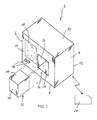
- FIG. 1 illustrated box or box-like structure in the form of a parallelepiped with two side walls 2 and 4, a bottom wall 8, a top wall 10, a rear wall 12 and a front wall 14th
- Size and shape of the housing 2 are designed according to the respective applications or applications, that is the in FIG. 1 shown shape of the housing 2 is purely exemplary and not limiting.
- the housing 2 is used to hold electrical and / or electronic components not shown in detail in the drawing and is in particular a control housing with a built-in control electronics, wherein the housing is EMC-secured in the manner of a faraday cage.
- the necessary technical measures for the EMC shielding of housings are general technical knowledge, so that will not be discussed further here.
- the housing 2 is in the illustrated embodiment, a control housing for medical or surgical purposes, so that the housing-side control electronics for the supply and control of appropriate treatment equipment or Treatment instruments serves. Said devices or instruments can be connected via corresponding sockets 16 or similar connectors which are present on the front wall 14. Also located in the front wall 14 is an operating and / or display panel 18, with which certain settings, function parameters, etc. are adjustable, monitorable or retrievable.
- An external control device 20 is particularly, but not exclusively, designed in the form of a foot control or a footswitch and includes at least one foot operated pedal for applying instructions or information to the housing side control electronics, which are then converted into instructions or control commands, optionally following appropriate programming which are output via the jacks 16.
- the external control device 20 communicates with the housing-side control electronics wirelessly by means of short-range communication, for example Bluetooth®, as in FIG. 1 schematically represented by the arrows. This means that between the control device 20 and the housing 2 no cable for unidirectional or bidirectional signal transmission runs.
- short-range communication for example Bluetooth®
- the housing 2 has in at least one of its side walls, in the illustrated embodiment in the front wall 14, at least one opening, behind which in the housing 2, a receiving space 22 is formed in the housing interior.
- the receiving space 22 is formed with the exception of the opening in the front wall 14 is substantially closed on all sides and therefore has the shown in the drawing or visible boundary walls 24, 26 and 28, and a bottom wall 30.
- the boundary wall 24 is the boundary wall 28 and the boundary wall 26 a visible in any of the figures boundary wall.
- the receiving space 22 is verifiable FIG. 1 for receiving a functional component 32, which according to the figures has an outer shape which is adapted to that of the receiving space 22 (in practice, the situation prevails that the receiving space 22 is to be adapted to the outer contour of the component 32; graphic representation of both the recording room 22 as well as the component 32 as purely exemplary or schematically illustrative).
- the functional component 32 is a functional unit or functional block that performs certain functions under the control of the housing-side control electronics, which in turn is commanded by the external control device 20.
- a concrete and non-limiting example of the functional component 32 is a liquid pump, for example a roller or peristaltic pump, with which cooling or rinsing liquid can be conveyed.
- Other examples of the functional component 32 would be, for example, compressed air generators, suction devices or the like.
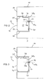
- FIGS. 2 and 3 show in simplified side sectional view, as the functional component 32 is inserted into the receiving space 22.
- the depth of the component 32 and the receiving space 22 is preferably designed such that, as evidenced by the FIGS. 2 and 3 a front surface 34 of the component 32 is substantially in-plane with the front wall 14 of the housing 2 when the component 32 is received in the receiving space 22.
- the component 32 is not or only slightly from the plane of the front wall 14 before.
- the flush or substantially flush receiving the component 32 in the receiving space 22 allows, in particular for safety reasons, but also due to aesthetic considerations, the receiving space 22 with inserted component 32 to close at least partially by a diaphragm not shown in the drawing.
- "Bend” here is any closure element understood, with which the opening of the receiving space 22 is at least partially closed, so for example, a flap, a roll closure, a slide or the like.
- an EMC-unsecured transmitter in the form of an EMC-unsecured transmitting and / or or receiving device provided.
- This transformer is in the FIGS. 2 and 3 illustrated by the reference numeral 36.
- the transmitter 36 may be formed, for example, as a transmitting / receiving antenna (transceiver) and communicates with the housing-side control electronics via a single- or multi-wire line 38a (FIG. FIG. 2 ) or 38b ( FIG. 3 ) in connection.
- components, drives, etc. inside the component 32 via a cable 40a ( FIG. 2 ) or a cable 40b ( FIG. 3 ) With the housing-side control electronics and / or a local power supply, etc. in connection.
- FIG. 2 is the transformer or the antenna 36 in a gap 42 between the outer periphery of the component 32 and the receiving space 22, that is, for example, between the boundary wall 28 and an upper surface 44 of the component 32.
- the transformer 36 may be fixed to the boundary wall 28 and the upper side 44 of the component 32 has a corresponding recess or recess 46, which is adapted in shape, size and shape to the transformer 36 and despite the located on the boundary wall 28 transformer 36 unimpeded insertion or withdrawal of the component 32 in or out the receiving space 22 allowed.
- the cable or line 38a is laid from the transmitter 36 through a corresponding opening in the bottom wall 30 to the housing-side control electronics.
- the line 38 in this case passes through the bottom wall 30 in a corresponding opening.
- the transmitter 36 is located inside the component 32, wherein the transmitter 36 can then be designed, for example, specifically for the respective component 32.
- FIG. 2 Preferably ends the cable or the line 40 a, which leads out of the component 32, in a connector 50 which is insertable into a corresponding mating connector 52 when the component 32 is completely in the Recording room 22 is included.
- a line 48a outgoing from the mating connector 52 then leads to the housing-side control electronics, a housing-side power supply, etc.
- the outgoing line 38b from the transmitter 36 is guided to the component-side line 40b and then passes via the connector 50 and the mating connector 52 to the housing-side line 48b.
- the transmitter (the antenna) 36 is in both embodiments, outside the EMC shield of the housing 2, an unobstructed communication between the external control device 20 and the housing-side control electronics is ensured.
- the transmitter 36 in the receiving space 22 and in the component 32 is virtually invisible and protected, that is, he contributes neither to any of the outer surfaces of the housing 2 in any way, nor is he in danger of bending, breakage or the like exposed.
- the outer surfaces of the housing 2 and in particular the two side walls 2 and 4 and the bottom wall 8 and the top wall 10 can be smooth, that is formed without projections, so that a plurality of inventively designed housing 2 side by side and / or überchrostapelbar.
- the insertion of the housing 2 into a device rack or a rack is not hindered by any protruding antenna elements or the like.
- the number of recording rooms is not on the FIG. 1 shown single number limited, but it can also be several such receiving spaces not only in the front wall 14, but be provided in the other outer walls of the housing 2.
- the receiving spaces 22 need not be the same size and / or the same shape.
- the functional component 32 is a fluid feed pump or fluid suction pump or another mechanically driven element, then in addition to the line 38a and / or the line 48a (48b), a mechanical drive can be guided through the bottom wall 30, for example one Drive shaft with a coupling element at the free end, which then comes into engagement with a corresponding counter-coupling element on the part of the component 32 when the component 32 has been inserted into the receiving space 22.
- the passage of the drive shaft through the bottom wall 30 is preferably designed fluid-tight.
- a housing for accommodating electrical and / or electronic components has been described so far, but in particular not exclusively a control housing with built-in control electronics, the housing being EMC-protected in the manner of a Faraday cage.
- at least one housing outer wall at least one receiving space, which is open towards the outside of the housing and is otherwise generally closed on all sides, is formed whose boundary walls are likewise designed to be EMC-proof.
- At least one EMC-unsecured transmitter in the form of an EMC-unsecured transmitting and / or receiving device, which is capable of producing wireless communication between the housing-side control electronics and an external control device, and a functional component which can be activated by the housing-side control electronics, can be arranged in the receiving space.
- the transmitter is preferably an antenna, the arrangement of which in the receiving space ensures that it lies outside the EMC protection or shielding.
- the functional component may e.g. a pump, in particular a peristaltic pump, which is protected by the arrangement in the receiving space and does not protrude from the housing disturbing.
Landscapes
- Engineering & Computer Science (AREA)
- Microelectronics & Electronic Packaging (AREA)
- Computer Networks & Wireless Communication (AREA)
- Infusion, Injection, And Reservoir Apparatuses (AREA)
- Casings For Electric Apparatus (AREA)
Abstract
Description
- Die vorliegende Erfindung betrifft ein Gehäuse zur Aufnahme von elektrischen und/oder elektronischen Bauteilen, insbesondere ein Steuergehäuse mit eingebauter Steuerungselektronik, wobei das Gehäuse nach Art eines faraday'schen Käfigs EMV-gesichert ist.
- Als ein mögliches, die Erfindung in keiner Weise einschränkendes Beispiel eines derartigen Gehäuses sei ein Gehäuse betrachtet, welches auf dem Gebiet der Medizin bzw. der Chirurgie Anwendung findet und welches von der Anmelderin der vorliegenden Erfindung unter der Bezeichnung "Microspeed® Uni" vertrieben wird.
- Dieses bekannte Gehäuse vereint eine Anzahl von Steuerungs- und Regelungsfunktionen in sich, wobei besagte Funktionen auf medizinische Geräte oder Werkzeuge angewendet werden, die für unterschiedliche medizinische, chirurgische oder kosmetische Anwendungen zum Einsatz gelangen. Die Geräte oder Werkzeuge werden über geräte- oder werkzeugseitige Stecker mit gehäuseseitigen Buchsen verbunden. Das Gehäuse selbst beziehungsweise die hierin aufgenommene Steuerungselektronik ist über eine mehrpolige Steckerverbindung und ein entsprechend mehrpoliges Kabel mit einem Fußschalter verbindbar, mit dem entsprechende Schalt- oder Funktionsanweisungen an die gehäuseseitige Steuerungselektronik ausgegeben werden können, welche dann wiederum in entsprechende Funktionen der medizinischen Geräte oder Werkzeuge umgesetzt werden. An der Frontseite des Gehäuses befindet sich darüber hinaus noch ein Display mit Touchbedienfeld, um separat von oder zusätzlich zu dem Fußschalter Steueranweisungen, Funktionsparameter etc. eingeben zu können.
- Weiterhin befindet sich an der Frontseite des Gehäuses eine dort an- oder aufgesetzte Pumpe, insbesondere eine Rollen- oder Peristaltikpumpe, mit welcher eine Kühl- und/oder Spülflüssigkeit zum Operations- oder Behandlungsfeld gefördert werden kann, um ein dort laufendes Werkzeug zu kühlen, das Operationsfeld zu spülen etc. Die Ansteuerung der Pumpe erfolgt in der Regel über den erwähnten Fußschalter.
- Da das Gehäuse elektrische und/oder elektronische Bauteile, also die Steuerungselektronik aufnimmt und mit der Pumpe eine Flüssigkeit, in der Regel Wasser gefördert wird, ist es aus sicherheitstechnischen Überlegungen unabdingbar, dass das Gehäuse, in welchem sich die Steuerungselektronik befindet und die Pumpe flüssigkeitsdicht voneinander abgegrenzt sind. Erreicht wird dies dadurch, dass die Pumpe bzw. das die Pumpe kapselnde Gehäuse an die Vorderseite des eigentlichen Steuerungsgehäuses angesetzt wird.
- Darüber hinaus muss das Gehäuse EMV-dicht ausgeführt werden, also nach Art eines faraday'schen Käfigs wirken, um betriebssicher arbeiten zu können.
- In letzter Zeit hat sich die Forderung nach einer draht- oder kabellosen Ansteuerungsmöglichkeit der gehäuseseitigen Steuerungselektronik ergeben, das heißt, die Verbindung zwischen dem Fußschalter und dem Gehäuse soll nicht mehr über das mehradrige Kabel sondern drahtlos über eine entsprechende Nahbereichs-Funktechnik erfolgen. Aufgrund der EMV-dichten oder EMV-gesicherten Ausführung des Gehäuses macht dies die Anordnung einer Sende- und/oder Empfangsvorrichtung außerhalb der Gehäuseabschirmung notwendig, damit die drahtlos übermittelten Befehle von dem Fußschalter empfangen werden können. Eine derartige, außerhalb des Gehäuses bzw. der Gehäuseabschirmung liegende Sende- und/oder Empfangsvorrichtung ist jedoch insofern nachteilig oder problematisch, als sie einen störenden An- oder Aufbau am Gehäuse darstellt, der in störender oder unschöner Art und Weise von der Außenkontur des Gehäuses vorsteht. Darüber hinaus kann ein derartiger An- oder Aufbau in nachteiliger Weise ein Aneinanderreihen oder Übereinanderstapeln mehrerer Steuerungsgehäuse oder deren Einschub in ein Rack be- oder verhindern.
- Gleichermaßen verhält es sich mit der an der Gehäusefront anbringbaren Pumpe: Sie steht in nicht unerheblichen Maß von der Fläche der Gehäusefront vor und ist insofern sowohl ästhetisch als auch in der Praxis, das heißt im Betrieb störend, als es sich um ein vorstehendes Hindernis handelt, welches naturgemäß berührungsempfindlich ist, an welchem sich Gegenstände oder vorbeigehende Personen verfangen können etc.
- Die Erfindung hat es sich demgegenüber zur Aufgabe gemacht, ein Gehäuse der in Frage stehenden Art derart auszugestalten, dass im praktischen Betrieb eine hohe Funktionalität und Sicherheit erreicht wird, wobei insbesondere ein uneingeschränkter drahtloser Kommunikationsweg zwischen der gehäuseseitigen Steuerungselektronik und einer externen Steuereinrichtung sichergestellt sein soll, ohne dass an dem Gehäuse unfallträchtige oder im Praxisbetrieb unpraktische An- oder Aufbauten vorhanden sein müssen.
- Zur Lösung dieser Aufgabe schlägt die vorliegende Erfindung ein Gehäuse für medizinische Zwecke vor, bei dem in wenigstens einer Gehäuseseitenwand wenigstens ein zur Gehäuseaußenseite hin offener und ansonsten allseitig im Wesentlichen geschlossener Aufnahmeraum ausgebildet ist, dessen Begrenzungswände EMV-gesichert ausgeführt sind. Weiterhin ist in dem Aufnahmeraum wenigstens ein EMV-ungesicherter Übertrager in Form einer EMV-ungesicherten Sende- und/oder Empfangsvorrichtung anordenbar, welche eine drahtlose Kommunikation zwischen der gehäuseseitigen Steuerungselektronik und einer externen Steuereinrichtung herzustellen vermag und weiterhin ist eine von der gehäuseseitigen Steuerungselektronik ansteuerbare funktionelle Komponente in dem EMV-gesicherten Aufnahmeraum anordenbar.
- Die von der gehäuseseitigen Steuerungselektronik ansteuerbare funktionelle Komponente, welche gemäß einer möglichen Ausgestaltungsform der vorliegenden Erfindung eine (medizinische) Pumpe, insbesondere eine Peristaltikpumpe sein kann, wird daher von der Gehäusefrontplatte, von der sie bislang um einen der Bautiefe der Pumpe oder des Pumpengehäuses entsprechenden Betrag vorstand, in den Aufnahmeraum verlagert, sodass idealerweise die funktionelle Komponente in dem Aufnahmeraum derart zu liegen kommt, dass die sichtbare Vorderseite der Komponente und die Gehäuseseitenwand, in der der Aufnahmeraum ausgebildet ist, im Wesentlichen eine Ebene bilden. Dadurch, dass die Begrenzungswände des Aufnahmeraums ebenfalls EMV-gesichert ausgeführt sind, erfolgt durch die Ausbildung des Aufnahmeraums in der wenigstens einen Gehäuseseitenwand keine Durchbrechung der EMV-Abschirmung des gesamten Gehäuses, sodass die Betriebssicherheit weiterhin gewährleistet ist. Da weiterhin der EMV-ungesicherte Übertrager in Form der Sende- und/oder Empfangsvorrichtung ebenfalls in dem Aufnahmeraum angeordnet ist, befindet sich der Übertrager einerseits außerhalb des EMV-gesicherten oder abgeschirmten Gehäuses, kann also eine uneingeschränkte Nahbereichs-Kommunikation mit der externen Steuereinrichtung durchführen, andererseits ist der Übertrager durch die Anordnung im Bereich des Aufnahmeraums von der Außenhülle des Gehäuses wegverlagert, stellt also keine störende Einheit an der Gehäuseaußenwand dar. Da schließlich der Aufnahmeraum durch seine Begrenzungswände allseitig im Wesentlichen geschlossen ist (mit Ausnahme der zur Gehäuseaußenseite hin weisenden Öffnung), ist die Betriebssicherheit trotz der Aufnahme der flüssigkeitsführenden Pumpe quasi im Inneren des Gehäuses uneingeschränkt gegeben.
- Vorteilhafte Weiterbildungen und Ausgestaltungen der Erfindung sind Gegenstand der Unteransprüche.
- Gemäß einer bevorzugten Ausgestaltungsform ist der EMV-ungesicherte Übertrager eine Antenne, beispielsweise eine Bluetooth®-Antenne zur Durchführung der drahtlosen Kommunikation zwischen der gehäuseseitigen Steuerungselektronik und der externen Steuereinrichtung, beispielsweise des Fußschalters oder der Fußschalter.
- Eine mögliche Ausführungsform der vorliegenden Erfindung schlägt vor, dass der Übertrager (die Antenne) und die von der gehäuseseitigen Steuerungselektronik ansteuerbare funktionelle Komponente (z. B. die Pumpe) zu einer Einheit zusammengefasst sind. Der Übertrager bzw. die Antenne befindet sich somit im Inneren der funktionellen Komponente, ist also quasi von dieser gekapselt oder eingehaust und zusätzlich geschützt.
- In einer anderen Ausgestaltungsform kann der Übertrager in einem Zwischenraum zwischen der funktionellen Komponente und den Begrenzungswänden des Aufnahmeraums angeordnet sein. Der Übertrager (die Antenne) ist somit aus der funktionellen Komponente herausgeführt, also ein dem Gehäuse zugeordnetes Bauteil, welches bei Entnahme der Komponente aus dem Aufnahmeraum in diesem verbleibt.
- Der Übertrager kann mit der gehäuseseitigen Steuerungselektronik über wenigstens eine abgeschirmte Kabelverbindung kommunizieren, wobei die abgeschirmte Kabelverbindung wenigstens ein Signalkabel und/oder wenigstens ein Energieversorgungskabel aufweist. Zwar ist es bei einer abgeschirmten Kabelverbindung unumgänglich, das oder die Kabel durch die Gehäusewand und damit durch die EMV-Abschirmung zu führen, jedoch ist die hierfür notwendige Durchtrittsöffnung in der EMV-Abschirmung bezogen auf die gesamte Abschirmungsfläche vernachlässigbar klein, sodass keinerlei Nachteile hieraus erwachsen.
- Die abgeschirmte Kabelverbindung kann weiterhin wenigstens eine lösbare Steckverbindung aufweisen. Dies erleichtert die Entnahme der Komponente aus dem Aufnahmeraum und insbesondere den Austausch verschiedener Komponenten untereinander, da hierzu lediglich die Steckverbindung gelöst werden muss.
- Die lösbare Steckverbindung kann weiterhin wenigstens einen Steckverbinder seitens der funktionellen Komponente und wenigstens einen komplementären Gegensteckverbinder z.B. seitens der Bodenwand des Aufnahmeraums aufweisen, wobei Steckverbinder und Gegensteckverbinder beim Einsetzen der funktionellen Komponente in den Aufnahmeraum miteinander kontaktieren. Dieses Verbindungsprinzip, welches an sich von Einschubgehäusen oder Racks bekannt ist, stellt eine besonders bevorzugte Ausgestaltungsform der Steckverbindung dar.
- Wie bereits weiter oben erläutert, kann gemäß einer Ausgestaltungsform die funktionelle Komponente eine Pumpe, insbesondere eine Peristaltikpumpe sein. Es versteht sich jedoch, dass der Gegenstand der vorliegenden Erfindung nicht hierauf beschränkt ist.
- Insbesondere aus sicherheitstechnischen Gründen, jedoch auch aufgrund ästhetischer Überlegungen kann es vorteilhaft sein, den Aufnahmeraum bei eingesetzter funktioneller Komponente, beispielsweise bei eingesetzter Pumpe, durch eine Blende zumindest teilweise zu verschließen. Unter "Biende" sei hierbei ein beliebiges Verschlusselement verstanden, mit welchem die Öffnung des Aufnahmeraums zumindest teilweise verschließbar ist, also beispielsweise eine Klappe, ein Rollverschluss, ein Schieber oder dergleichen.
- Weitere Einzelheiten, Aspekte und Vorteile der vorliegenden Erfindung ergeben sich besser aus der nachfolgenden Beschreibung von Ausführungsformen anhand der Zeichnung.
- Es zeigt:
-
Figur 1 eine schematisch vereinfachte perspektivische Ansicht eines erfindungsgemäßen Gehäuses und einer in dem Gehäuse anordenbaren funktionellen Komponente; -
Figur 2 eine stark vereinfachte Seitenschnittansicht durch das erfindungsgemäße Gehäuse gemäß einer Ausführungsform; und -
Figur 3 eineFigur 2 entsprechende Ansicht einer weiteren Ausführungsform. - Eine in der Zeichnung insgesamt mit 2 bezeichnetes Gehäuse hat den in
Figur 1 dargestellten schachtel- oder boxartigen Aufbau in Form eines Parallelflächers mit zwei Seitenwänden 2 und 4, einer Bodenwand 8, einer Deckenwand 10, einer Rückwand 12 und einer Vorderwand 14. - Größe und Form des Gehäuses 2 sind den jeweiligen Anwendungsfällen oder Einsatzzwecken entsprechend gestaltet, das heißt die in
Figur 1 dargestellte Form des Gehäuses 2 ist rein beispielhaft und nicht einschränkend. - Das Gehäuse 2 dient zur Aufnahme von in der Zeichnung nicht näher dargestellten elektrischen und/oder elektronischen Bauteilen und ist insbesondere ein Steuerungsgehäuse mit einer eingebauten Steuerungselektronik, wobei das Gehäuse nach Art eines faraday'schen Käfigs EMV-gesichert ist. Die notwendigen technischen Maßnahmen zur EMV-Abschirmung von Gehäusen sind technisches Allgemeingut, sodass nicht näher hierauf eingegangen wird.
- Das Gehäuse 2 sei im dargestellten Ausführungsbeispiel ein Steuerungsgehäuse für medizinische oder chirurgische Zwecke, sodass die gehäuseseitige Steuerungselektronik zur Versorgung und Ansteuerung entsprechender Behandlungsgeräte oder Behandlungsinstrumente dient. Besagte Geräte oder Instrumente können über entsprechende Buchsen 16 oder ähnliche Steckverbindungen, welche an der Vorderwand 14 vorhanden sind, angeschlossen werden. Ebenfalls befindet sich in der Vorderwand 14 ein Bedienungs- und/oder Anzeigefeld 18, mit welchem bestimmte Einstellungen, Funktionsparameter etc. einstellbar, überwachbar oder abrufbar sind.
- Eine externe Steuereinrichtung 20 ist insbesondere, jedoch nicht ausschließlich in Form einer Fußsteuerung oder eines Fußschalters ausgelegt und enthält wenigstens ein fußbetätigtes Pedal, um die gehäuseseitige Steuerungselektronik mit Befehlen oder Informationen zu beaufschlagen, welche dann - gegebenenfalls einer entsprechenden Programmierung folgend - in Anweisungen oder Steuerungsbefehle umgesetzt werden, welche über die Buchsen 16 ausgegeben werden.
- Die externe Steuereinrichtung 20 kommuniziert mit der gehäuseseitigen Steuerungselektronik drahtlos mittels einer Nahbereichskommunikation, beispielsweise Bluetooth®, wie in
Figur 1 schematisch durch die Pfeile dargestellt. Dies bedeutet, dass zwischen der Steuereinrichtung 20 und dem Gehäuse 2 kein Kabel zur uni- oder bidirektionalen Signalübertragung verläuft. - Das Gehäuse 2 weist in wenigstens einer seiner Seitenwände, im dargestellten Ausführungsbeispiel in der Vorderwand 14, wenigstens eine Öffnung auf, hinter der in dem Gehäuse 2 ein Aufnahmeraum 22 in das Gehäuseinnere hinein ausgebildet ist. Der Aufnahmeraum 22 ist mit Ausnahme der Öffnung in der Vorderwand 14 im Wesentlichen allseitig geschlossen ausgebildet und weist demzufolge die in der Zeichnung dargestellten bzw. sichtbaren Begrenzungswände 24, 26 und 28, sowie eine Bodenwand 30 auf. Der Begrenzungswand 24 liegt die Begrenzungswand 28 gegenüber und der Begrenzungswand 26 eine in keiner der Figuren sichtbare Begrenzungswand.
- Der Aufnahmeraum 22 dient ausweislich
Figur 1 zur Aufnahme einer funktionellen Komponente 32, welche gemäß den Figuren eine äußere Formgebung hat, welche an diejenige des Aufnahmeraums 22 angepasst ist (wobei in der Praxis die Situation überwiegen dürfte, dass der Aufnahmeraum 22 an die Außenkontur der Komponente 32 anzupassen ist; insofern ist die zeichnerische Darstellung sowohl des Aufnahmeraums 22 als auch der Komponente 32 als rein exemplarisch bzw. schematisch veranschaulichend zu verstehen). - Die funktionelle Komponente 32 ist eine Funktionseinheit oder ein Funktionsblock, welcher unter Steuerung der gehäuseseitigen Steuerungselektronik, welche wiederum von der externen Steuereinrichtung 20 befehligt wird, bestimmte Funktionen ausführt. Ein konkretes und nicht einschränkendes Beispiel für die funktionelle Komponente 32 sei eine Flüssigkeitspumpe, beispielsweise eine Rollen- oder Peristaltikpumpe, mit der Kühl- oder Spülflüssigkeit förderbar ist. Andere Beispiele für die funktionelle Komponente 32 wären beispielsweise Drucklufterzeuger, Absaugvorrichtungen oder dergleichen.
- Um die EMV-Sicherung oder EMV-Kapselung des Gehäuses 2 durch den Aufnahmeraum 22 nicht zu unterbrechen, sind sämtliche den Aufnahmeraum 22 begrenzenden Wände (Seitenwände 24, 26, 28 und die der Wand 26 gegenüberliegende Wand, sowie Bodenwand 30) ebenfalls EMV-gesichert ausgeführt.
- Die
Figuren 2 und 3 zeigen in vereinfachter seitlicher Schnittdarstellung, wie die funktionelle Komponente 32 in den Aufnahmeraum 22 eingeschoben ist. Die Tiefe der Komponente 32 sowie des Aufnahmeraums 22 ist bevorzugt derart ausgelegt, dass ausweislich derFiguren 2 und 3 eine Vorderfläche 34 der Komponente 32 mit der Vorderwand 14 des Gehäuses 2 im Wesentlichen in einer Ebene liegt, wenn die Komponente 32 in dem Aufnahmeraum 22 aufgenommen ist. Mit anderen Worten, die Komponente 32 steht nicht oder nur unwesentlich von der Ebene der Vorderwand 14 vor. - Die bündige oder im wesentlichen bündige Aufnahme der Komponente 32 im Aufnahmeraum 22 erlaubt, dass Insbesondere aus sicherheitstechnischen Gründen, jedoch auch aufgrund ästhetischer Überlegungen, den Aufnahmeraum 22 bei eingesetzter Komponente 32 durch eine in der Zeichnung nicht näher dargestellte Blende zumindest teilweise zu verschließen. Unter "Biende" sei hierbei ein beliebiges Verschlusselement verstanden, mit welchem die Öffnung des Aufnahmeraums 22 zumindest teilweise verschließbar ist, also beispielsweise eine Klappe, ein Rollverschluss, ein Schieber oder dergleichen.
- Um trotz der EMV-gesicherten Ausführung des Gehäuses 2 (und des Aufnahmeraums 22) eine drahtlose Kommunikation zwischen der externen Steuereinrichtung und der gehäuseseitigen Steuerungselektronik zu ermöglichen, ist seitens des Gehäuses 2 ein EMV-ungesicherter Übertrager in Form einer EMV-ungesicherten Sende- und/oder Empfangsvorrichtung vorgesehen. Dieser Übertrager ist in den
Figuren 2 und 3 mit den Bezugszeichen 36 veranschaulicht. Der Übertrager 36 kann beispielsweise als Sende/Empfangsantenne (Transceiver) ausgebildet sein und steht mit der gehäuseseitigen Steuerungselektronik über eine ein- oder mehradrige Leitung 38a (Figur 2 ) oder 38b (Figur 3 ) in Verbindung. Weiterhin stehen Bauteile, Antriebe etc. im Inneren der Komponente 32 über ein Kabel 40a (Figur 2 ) oder ein Kabel 40b (Figur 3 ) mit der gehäuseseitigen Steuerungselektronik und/oder einem dortigen Netzteil etc. in Verbindung. - In dem Ausführungsbeispiel von
Figur 2 befindet sich der Übertrager oder die Antenne 36 in einem Zwischenraum 42 zwischen dem Außenumfang der Komponente 32 und dem Aufnahmeraum 22, das heißt z.B. zwischen der Begrenzungswand 28 und einer Oberseite 44 der Komponente 32. Der Übertrager 36 kann hierbei an der Begrenzungswand 28 festgelegt sein und die Oberseite 44 der Komponente 32 weist eine entsprechende Ausnehmung oder Vertiefung 46 auf, welche in Form, Größe und Verlauf an den Übertrager 36 angepasst ist und trotz des sich an der Begrenzungswand 28 befindlichen Übertragers 36 ein ungehindertes Einschieben oder Herausziehen der Komponente 32 in oder aus dem Aufnahmeraum 22 gestattet. - Das Kabel oder die Leitung 38a ist ausgehend vom Übertrager 36 durch eine entsprechende Öffnung in der Bodenwand 30 zu der gehäuseseitigen Steuerungselektronik gelegt. Die Leitung 38 durchtritt hierbei die Bodenwand 30 in einer entsprechenden Öffnung.
- Im Ausführungsbeispiel von
Figur 3 befindet sich der Übertrager 36 im Inneren der Komponente 32, wobei der Übertrager 36 dann beispielsweise auch spezifisch für die jeweilige Komponente 32 ausgelegt sein kann. - Gemäß
Figur 2 endet bevorzugt das Kabel oder die Leitung 40a, welche aus der Komponente 32 herausführt, in einem Steckverbinder 50, der in einen entsprechenden Gegensteckverbinder 52 einführbar ist, wenn die Komponente 32 vollständig in dem Aufnahmeraum 22 aufgenommen ist. Eine vom Gegensteckverbinder 52 ausgehende Leitung 48a führt dann zu der gehäuseseitigen Steuerungselektronik, einer gehäuseseitigen Energieversorgung etc. - Im Ausführungsbeispiel von
Figur 3 ist die vom Übertrager 36 ausgehende Leitung 38b auf die komponentenseitige Leitung 40b geführt und geht dann über den Steckverbinder 50 und den Gegensteckverbinder 52 zu der gehäuseseitigen Leitung 48b. - Dadurch, dass der Übertrager (die Antenne) 36 in beiden Ausführungsbeispielen außerhalb der EMV-Abschirmung des Gehäuses 2 liegt, ist eine ungehinderte Kommunikation zwischen der externen Steuereinrichtung 20 und der gehäuseseitigen Steuerungselektronik gewährleistet. Darüber hinaus ist der Übertrager 36 in dem Aufnahmeraum 22 bzw. in der Komponente 32 quasi unsichtbar und geschützt, das heißt, er trägt weder an einer der Außenflächen des Gehäuses 2 in irgendeiner Weise auf, noch ist er der Gefahr von Verbiegen, Bruch oder dergleichen ausgesetzt. Die Außenflächen des Gehäuses 2 und hier insbesondere die beiden Seitenwände 2 und 4 und die Bodenwand 8 und die Deckenwand 10 können glatt, das heißt ohne Vorsprünge ausgebildet werden, sodass auch eine Mehrzahl erfindungsgemäß ausgebildeter Gehäuse 2 neben- und/oder übereinanderstapelbar ist. Auch ist der Einschub des Gehäuses 2 in einen Geräteträger oder ein Rack nicht durch irgendwelche vorstehenden Antennenelemente oder dergleichen behindert.
- Dadurch, dass die Begrenzungswände des Aufnahmeraums 22 im Wesentlichen geschlossen sind (mit Ausnahme der Durchführung der Leitung 38a in
Figur 2 , sowie des Gegensteckverbinders 52 in denFiguren 2 und 3 , wobei diese Durchführungen ohne weiteres auch fluiddicht ausgelegt werden können), besteht keine Gefahr, dass dann, wenn die Komponente 32 eine Fluid Förderpumpe oder Fluid Absaugpumpe ist, das jeweils in Frage stehende Fluid in das Innere des Gehäuses 2 gelangen kann. - Es versteht sich, dass im Rahmen der vorliegenden Erfindung noch weitere Modifikationen oder Abwandlungen denkbar sind. So ist beispielsweise die Anzahl der Aufnahmeräume nicht auf die
Figur 1 dargestellte Einzelzahl beschränkt, sondern es können auch mehrere derartiger Aufnahmeräume nicht nur in der Vorderwand 14, sondern auch in den übrigen Außenwänden des Gehäuses 2 vorgesehen werden. Auch müssen die Aufnahmeräume 22 nicht von gleicher Größe und/oder gleicher Form sein. - Ist - wie weiter oben bereits ausgeführt - die funktionelle Komponente 32 eine Fluidförderpumpe oder Fluidabsaugpumpe oder ein anderes mechanisch angetriebenes Element, kann zusätzlich zu der Leitung 38a und/oder der Leitung 48a (48b) ein mechanischer Antrieb durch die Bodenwand 30 geführt werden, beispielsweise eine Antriebswelle mit einem Kupplungselement am freien Ende, welches dann mit einem entsprechenden Gegenkupplungselement seitens der Komponente 32 in Eingriff gelangt, wenn die Komponente 32 in den Aufnahmeraum 22 eingeschoben worden ist. Die Durchführung der Antriebswelle durch die Bodenwand 30 ist bevorzugt fluiddicht ausgelegt.
- Beschrieben wurde insoweit zusammenfassend ein Gehäuse zur Aufnahme von elektrischen und/oder elektronischen Bauteilen, insbesondere jedoch nicht ausschließlich ein Steuerungsgehäuse mit eingebauter Steuerungselektronik, wobei das Gehäuse nach Art eines Faraday'schen Käfigs EMV-gesichert ist. In wenigstens einer Gehäuseaußenwand ist wenigstens ein zur Gehäuseaußenseite hin offener und ansonsten allseitig im wesentlichen geschlossener Aufnahmeraum ausgebildet, dessen Begrenzungswände ebenfalls EMV-gesichert ausgeführt sind. In dem Aufnahmeraum sind wenigstens ein EMV-ungesicherter Übertrager in Form einer EMV-ungesicherten Sende- und/oder Empfangsvorrichtung, welche eine drahtlose Kommunikation zwischen der gehäuseseitigen Steuerungselektronik und einer externen Steuereinrichtung herzustellen vermag und eine von der gehäuseseitigen Steuerungselektronik ansteuerbare funktionelle Komponente anordenbar. Der Übertrager ist bevorzugt eine Antenne, wobei deren Anordnung in dem Aufnahmeraum sicherstellt, dass sie außerhalb der EMV-Absicherung oder -Abschirmung liegt. Die funktionelle Komponente kann z.B. eine Pumpe, insbesondere eine Peristaltikpumpe sein, welche durch die Anordnung in dem Aufnahmeraum geschützt ist und nicht störend vom Gehäuse vorragt.
Claims (10)
- Gehäuse einer medizinischen Vorrichtung zur Aufnahme von elektrischen und/oder elektronischen Bauteilen, insbesondere medizinisches Steuerungsgehäuse mit eingebauter Steuerungselektronik, wobei das Gehäuse (2) nach Art eines Faraday'schen Käfigs EMV-gesichert ist, dadurch gekennzeichnet, dass
in wenigstens einer Gehäuseaußenwand (14) wenigstens ein zur Gehäuseaußenseite hin offener und ansonsten allseitig im wesentlichen geschlossener Aufnahmeraum (22) ausgebildet ist, dessen Begrenzungswände (24, 26, 28, 30) ebenfalls EMV-gesichert ausgeführt sind; und
in dem Aufnahmeraum (22) wenigstens ein EMV-ungesicherter Übertrager (36) in Form einer EMV-ungesicherten Sende- und/oder Empfangsvorrichtung, welche eine drahtlose Kommunikation zwischen der gehäuseseitigen Steuerungselektronik und einer externen Steuereinrichtung (20) herzustellen vermag und eine von der gehäuseseitigen Steuerungselektronik ansteuerbare funktionelle Komponente (32) anordenbar sind. - Gehäuse nach Anspruch 1, dadurch gekennzeichnet, dass der Übertrager (36) eine Antenne ist.
- Gehäuse nach Anspruch 1 oder 2, dadurch gekennzeichnet, dass der Übertrager (36) und die von der gehäuseseitigen Steuerungselektronik ansteuerbare funktionelle Komponente (32) zu einer Einheit zusammengefasst sind.
- Gehäuse nach Anspruch 1 oder 2, dadurch gekennzeichnet, dass der Übertrager (36) aus der funktionellen Komponente (32) herausgeführt und in einem Zwischenraum (42) zwischen der funktionellen Komponente (32) und den Begrenzungswänden (24, 26, 28, 30) des Aufnahmeraums (22) angeordnet ist.
- Gehäuse nach einem der Ansprüche 1 bis 4, dadurch gekennzeichnet, dass der Übertrager (36) mit der gehäuseseitigen Steuerungselektronik über wenigstens eine abgeschirmte Kabelverbindung (38a, 38b) kommuniziert.
- Gehäuse nach Anspruch 5, dadurch gekennzeichnet, dass die abgeschirmte Kabelverbindung (38a, 38b) wenigstens ein Signalkabel und/oder wenigstens ein Energieversorgungskabel aufweist.
- Gehäuse nach Anspruch 5 oder 6, dadurch gekennzeichnet, dass die abgeschirmte Kabelverbindung (38a, 38b) wenigstens eine lösbare Steckverbindung aufweist.
- Gehäuse nach Anspruch 7, dadurch gekennzeichnet, dass die lösbare Steckverbindung wenigstens einen Steckverbinder (50) seitens der funktionellen Komponente (32) und wenigstens einen komplementären Gegensteckverbinder (52) seitens einer Begrenzungswand, insbesondere einer Bodenwand (30) des Aufnahmeraums (22) aufweist, wobei Steckverbinder (50) und Gegensteckverbinder (52) beim Einsetzen der funktionellen Komponente (32) in den Aufnahmeraum (22) miteinander kontaktieren.
- Gehäuse nach einem der vorhergehenden Ansprüche, dadurch gekennzeichnet, dass die funktionelle Komponente (32) eine Pumpe, insbesondere eine Peristaltikpumpe ist.
- Gehäuse nach einem der vorhergehenden Ansprüche, dadurch gekennzeichnet, dass der Aufnahmeraum (22) bei eingesetzter funktioneller Komponente (32) durch eine Blende zumindest teilweise verschließbar ist.
Applications Claiming Priority (1)
| Application Number | Priority Date | Filing Date | Title |
|---|---|---|---|
| DE102012100882A DE102012100882A1 (de) | 2012-02-02 | 2012-02-02 | Gehäuse zur Aufnahme von elektrischen und/oder elektronischen Bauteilen |
Publications (3)
| Publication Number | Publication Date |
|---|---|
| EP2624677A2 true EP2624677A2 (de) | 2013-08-07 |
| EP2624677A3 EP2624677A3 (de) | 2015-03-11 |
| EP2624677B1 EP2624677B1 (de) | 2018-08-22 |
Family
ID=47502649
Family Applications (1)
| Application Number | Title | Priority Date | Filing Date |
|---|---|---|---|
| EP12193054.9A Active EP2624677B1 (de) | 2012-02-02 | 2012-11-16 | Gehäuse zur Aufnahme von elektrischen und/oder elektronischen Bauteilen |
Country Status (3)
| Country | Link |
|---|---|
| US (1) | US9215819B2 (de) |
| EP (1) | EP2624677B1 (de) |
| DE (2) | DE102012100882A1 (de) |
Families Citing this family (9)
| Publication number | Priority date | Publication date | Assignee | Title |
|---|---|---|---|---|
| US9660336B2 (en) | 2013-02-07 | 2017-05-23 | Kevan ANDERSON | Systems, devices and methods for transmitting electrical signals through a faraday cage |
| WO2016062338A1 (en) | 2014-10-22 | 2016-04-28 | Abb Technology Ltd | A control unit comprising an antenna for wireless communication with a remote unit |
| JP6246764B2 (ja) | 2015-06-30 | 2017-12-13 | 株式会社東芝 | バスバー及びバッテリーモジュール |
| WO2017091903A1 (en) * | 2015-12-03 | 2017-06-08 | Innovere Medical Inc. | Systems, devices and methods for wireless transmission of signals through a faraday cage |
| JP6918553B2 (ja) * | 2017-04-05 | 2021-08-11 | 株式会社マキタ | 携帯用加工機 |
| BR112019023421A2 (pt) | 2017-05-09 | 2020-06-16 | Innovere Medical Inc. | Sistema de geração de imagem ressonante magnética e de comunicação, e, sistema de comunicação sem fio. |
| DE102022108255A1 (de) * | 2022-04-06 | 2023-10-12 | Aesculap Ag | Elektrische medizinische Vorrichtung mit einer Antenne |
| US20240040756A1 (en) * | 2022-07-28 | 2024-02-01 | Te Connectivity Solutions Gmbh | Power connector having an emi enclosure |
| CN117269206B (zh) * | 2023-10-13 | 2025-11-07 | 上海超群检测科技股份有限公司 | X射线发射装置的壳体模组及x射线检测仪 |
Family Cites Families (11)
| Publication number | Priority date | Publication date | Assignee | Title |
|---|---|---|---|---|
| JP2705392B2 (ja) * | 1991-09-04 | 1998-01-28 | 日本電気株式会社 | 携帯無線機 |
| US5183404A (en) * | 1992-04-08 | 1993-02-02 | Megahertz Corporation | Systems for connection of physical/electrical media connectors to computer communications cards |
| US5918163A (en) * | 1995-03-31 | 1999-06-29 | Compaq Computer Corporation | Electronic card assembly having a retractable antenna |
| DE19652551C1 (de) * | 1996-12-17 | 1998-08-13 | Siemens Ag | Hochpoliger geschirmter Kabelstecker |
| DE19729177A1 (de) * | 1997-07-08 | 1999-01-14 | Kaltenbach & Voigt | Ärztliche Behandlungsvorrichtung |
| US6333860B1 (en) * | 2000-03-20 | 2001-12-25 | 3Com Corporation | Emi shield with connector cover extension |
| JP2001332914A (ja) * | 2000-05-22 | 2001-11-30 | Honda Tsushin Kogyo Co Ltd | アンテナユニット付きカード |
| JP2002341965A (ja) * | 2001-05-14 | 2002-11-29 | Alps Electric Co Ltd | カードを備えた情報機器 |
| JP4286198B2 (ja) * | 2004-09-01 | 2009-06-24 | オリンパス株式会社 | フットスイッチ及び出力システム |
| TWI380501B (en) * | 2007-08-22 | 2012-12-21 | Wistron Corp | Antenna structure and related expansion card and computer apparatus |
| DE102009018143A1 (de) | 2009-04-08 | 2010-10-14 | Aesculap Ag | Chirurgische Motorsteuerungs- und/oder -regelungsvorrichtung, chirurgisches Antriebssystem und Verfahren zum Steuern und/oder Regeln einer chirurgischen Antriebseinheit |
-
2012
- 2012-02-02 DE DE102012100882A patent/DE102012100882A1/de not_active Withdrawn
- 2012-11-16 DE DE202012104438U patent/DE202012104438U1/de not_active Expired - Lifetime
- 2012-11-16 EP EP12193054.9A patent/EP2624677B1/de active Active
- 2012-11-30 US US13/690,429 patent/US9215819B2/en active Active
Non-Patent Citations (1)
| Title |
|---|
| None |
Also Published As
| Publication number | Publication date |
|---|---|
| DE202012104438U1 (de) | 2012-12-03 |
| US20130201651A1 (en) | 2013-08-08 |
| DE102012100882A1 (de) | 2013-08-08 |
| US9215819B2 (en) | 2015-12-15 |
| EP2624677A3 (de) | 2015-03-11 |
| EP2624677B1 (de) | 2018-08-22 |
Similar Documents
| Publication | Publication Date | Title |
|---|---|---|
| EP2624677B1 (de) | Gehäuse zur Aufnahme von elektrischen und/oder elektronischen Bauteilen | |
| EP2904982B1 (de) | Elektrochirurgisches Gerät mit einem Buchseneinsatz, Set mit einem Entnahmewerkzeug und Verfahren zum entnehmen eines Buchseneinsatzes | |
| EP1947493B1 (de) | Steckverbindersystem und Schutzvorrichtung für optischen Steckverbinder | |
| EP2164139B1 (de) | Medizintechnisches Gerät und medizintechnische Geräteanordnung | |
| DE102013108083B3 (de) | Verdeckt liegendes Türband mit elektrischer Verbindung | |
| EP3877639B1 (de) | Steckadapter zum andocken an ein magnetventil | |
| EP3091152B1 (de) | Schliesssystem | |
| EP2119862A2 (de) | Torantrieb | |
| DE112019000255T5 (de) | Elektrische Türöffnungs- und Schließvorrichtung mit Kupplungsvorrichtung | |
| DE102016209200A1 (de) | Verbindungsstück | |
| DE202013009038U1 (de) | Elektrisches Steckvorrichtungssystem mit Verschlusseinrichtung | |
| EP3139454A1 (de) | Elektrisches gerät für die montage im innern eines schaltschranks | |
| EP3758157B1 (de) | Gerät mit serviceschnittstelle und verfahren zur wartung des geräts | |
| DE202012100358U1 (de) | Gehäuse zur Aufnahme von elektrischen und/oder elektronischen Bauteilen | |
| DE102007045400A1 (de) | Netzstecker | |
| EP1420330A2 (de) | Stromversorgung für ein elektrisches Gerät | |
| WO2008049522A1 (de) | Vorrichtung zur verbindung von leitungen | |
| WO2015128171A1 (de) | Vorrichtung zur bereitstellung einer abgedichteten kabeldurchführung und wechselrichter | |
| EP3048671A1 (de) | Einbaubuchse für eine kommunikationseinheit sowie kommunikationseinheit | |
| AT518011B1 (de) | Anordnung umfassend ein elektrisches Gerät und ein Verbindungskabel | |
| EP2930808A1 (de) | Elektrisches oder elektronisches Installationsgerät | |
| DE202024105014U1 (de) | Adaptervorrichtung für drahtlose Kopfhörer | |
| DE102021004837B4 (de) | Aufnahme- und Festlegevorrichtung, System, Schaltschrank und Anschlusssystem | |
| DE202020106219U1 (de) | Elektrischer Steckverbinder und elektrische Steckverbinderanordnung | |
| DE102006013944B3 (de) | Ankopplungsvorrichtung mit steckbarem Modul zur Ankopplung eines Diagnosegeräts |
Legal Events
| Date | Code | Title | Description |
|---|---|---|---|
| PUAI | Public reference made under article 153(3) epc to a published international application that has entered the european phase |
Free format text: ORIGINAL CODE: 0009012 |
|
| AK | Designated contracting states |
Kind code of ref document: A2 Designated state(s): AL AT BE BG CH CY CZ DE DK EE ES FI FR GB GR HR HU IE IS IT LI LT LU LV MC MK MT NL NO PL PT RO RS SE SI SK SM TR |
|
| AX | Request for extension of the european patent |
Extension state: BA ME |
|
| PUAL | Search report despatched |
Free format text: ORIGINAL CODE: 0009013 |
|
| AK | Designated contracting states |
Kind code of ref document: A3 Designated state(s): AL AT BE BG CH CY CZ DE DK EE ES FI FR GB GR HR HU IE IS IT LI LT LU LV MC MK MT NL NO PL PT RO RS SE SI SK SM TR |
|
| AX | Request for extension of the european patent |
Extension state: BA ME |
|
| RIC1 | Information provided on ipc code assigned before grant |
Ipc: H01Q 1/24 20060101ALI20150202BHEP Ipc: H05K 9/00 20060101AFI20150202BHEP Ipc: H01Q 17/00 20060101ALI20150202BHEP |
|
| 17P | Request for examination filed |
Effective date: 20150910 |
|
| RBV | Designated contracting states (corrected) |
Designated state(s): AL AT BE BG CH CY CZ DE DK EE ES FI FR GB GR HR HU IE IS IT LI LT LU LV MC MK MT NL NO PL PT RO RS SE SI SK SM TR |
|
| GRAP | Despatch of communication of intention to grant a patent |
Free format text: ORIGINAL CODE: EPIDOSNIGR1 |
|
| INTG | Intention to grant announced |
Effective date: 20180222 |
|
| GRAS | Grant fee paid |
Free format text: ORIGINAL CODE: EPIDOSNIGR3 |
|
| GRAJ | Information related to disapproval of communication of intention to grant by the applicant or resumption of examination proceedings by the epo deleted |
Free format text: ORIGINAL CODE: EPIDOSDIGR1 |
|
| GRAL | Information related to payment of fee for publishing/printing deleted |
Free format text: ORIGINAL CODE: EPIDOSDIGR3 |
|
| GRAR | Information related to intention to grant a patent recorded |
Free format text: ORIGINAL CODE: EPIDOSNIGR71 |
|
| GRAA | (expected) grant |
Free format text: ORIGINAL CODE: 0009210 |
|
| INTC | Intention to grant announced (deleted) | ||
| AK | Designated contracting states |
Kind code of ref document: B1 Designated state(s): AL AT BE BG CH CY CZ DE DK EE ES FI FR GB GR HR HU IE IS IT LI LT LU LV MC MK MT NL NO PL PT RO RS SE SI SK SM TR |
|
| INTG | Intention to grant announced |
Effective date: 20180717 |
|
| REG | Reference to a national code |
Ref country code: GB Ref legal event code: FG4D Free format text: NOT ENGLISH |
|
| REG | Reference to a national code |
Ref country code: CH Ref legal event code: EP |
|
| REG | Reference to a national code |
Ref country code: AT Ref legal event code: REF Ref document number: 1034037 Country of ref document: AT Kind code of ref document: T Effective date: 20180915 |
|
| REG | Reference to a national code |
Ref country code: IE Ref legal event code: FG4D Free format text: LANGUAGE OF EP DOCUMENT: GERMAN |
|
| REG | Reference to a national code |
Ref country code: DE Ref legal event code: R096 Ref document number: 502012013282 Country of ref document: DE |
|
| REG | Reference to a national code |
Ref country code: NL Ref legal event code: MP Effective date: 20180822 |
|
| REG | Reference to a national code |
Ref country code: LT Ref legal event code: MG4D |
|
| PG25 | Lapsed in a contracting state [announced via postgrant information from national office to epo] |
Ref country code: NO Free format text: LAPSE BECAUSE OF FAILURE TO SUBMIT A TRANSLATION OF THE DESCRIPTION OR TO PAY THE FEE WITHIN THE PRESCRIBED TIME-LIMIT Effective date: 20181122 Ref country code: SE Free format text: LAPSE BECAUSE OF FAILURE TO SUBMIT A TRANSLATION OF THE DESCRIPTION OR TO PAY THE FEE WITHIN THE PRESCRIBED TIME-LIMIT Effective date: 20180822 Ref country code: RS Free format text: LAPSE BECAUSE OF FAILURE TO SUBMIT A TRANSLATION OF THE DESCRIPTION OR TO PAY THE FEE WITHIN THE PRESCRIBED TIME-LIMIT Effective date: 20180822 Ref country code: IS Free format text: LAPSE BECAUSE OF FAILURE TO SUBMIT A TRANSLATION OF THE DESCRIPTION OR TO PAY THE FEE WITHIN THE PRESCRIBED TIME-LIMIT Effective date: 20181222 Ref country code: GR Free format text: LAPSE BECAUSE OF FAILURE TO SUBMIT A TRANSLATION OF THE DESCRIPTION OR TO PAY THE FEE WITHIN THE PRESCRIBED TIME-LIMIT Effective date: 20181123 Ref country code: FI Free format text: LAPSE BECAUSE OF FAILURE TO SUBMIT A TRANSLATION OF THE DESCRIPTION OR TO PAY THE FEE WITHIN THE PRESCRIBED TIME-LIMIT Effective date: 20180822 Ref country code: NL Free format text: LAPSE BECAUSE OF FAILURE TO SUBMIT A TRANSLATION OF THE DESCRIPTION OR TO PAY THE FEE WITHIN THE PRESCRIBED TIME-LIMIT Effective date: 20180822 Ref country code: BG Free format text: LAPSE BECAUSE OF FAILURE TO SUBMIT A TRANSLATION OF THE DESCRIPTION OR TO PAY THE FEE WITHIN THE PRESCRIBED TIME-LIMIT Effective date: 20181122 Ref country code: LT Free format text: LAPSE BECAUSE OF FAILURE TO SUBMIT A TRANSLATION OF THE DESCRIPTION OR TO PAY THE FEE WITHIN THE PRESCRIBED TIME-LIMIT Effective date: 20180822 |
|
| PG25 | Lapsed in a contracting state [announced via postgrant information from national office to epo] |
Ref country code: AL Free format text: LAPSE BECAUSE OF FAILURE TO SUBMIT A TRANSLATION OF THE DESCRIPTION OR TO PAY THE FEE WITHIN THE PRESCRIBED TIME-LIMIT Effective date: 20180822 Ref country code: HR Free format text: LAPSE BECAUSE OF FAILURE TO SUBMIT A TRANSLATION OF THE DESCRIPTION OR TO PAY THE FEE WITHIN THE PRESCRIBED TIME-LIMIT Effective date: 20180822 Ref country code: LV Free format text: LAPSE BECAUSE OF FAILURE TO SUBMIT A TRANSLATION OF THE DESCRIPTION OR TO PAY THE FEE WITHIN THE PRESCRIBED TIME-LIMIT Effective date: 20180822 |
|
| PG25 | Lapsed in a contracting state [announced via postgrant information from national office to epo] |
Ref country code: PL Free format text: LAPSE BECAUSE OF FAILURE TO SUBMIT A TRANSLATION OF THE DESCRIPTION OR TO PAY THE FEE WITHIN THE PRESCRIBED TIME-LIMIT Effective date: 20180822 Ref country code: EE Free format text: LAPSE BECAUSE OF FAILURE TO SUBMIT A TRANSLATION OF THE DESCRIPTION OR TO PAY THE FEE WITHIN THE PRESCRIBED TIME-LIMIT Effective date: 20180822 Ref country code: RO Free format text: LAPSE BECAUSE OF FAILURE TO SUBMIT A TRANSLATION OF THE DESCRIPTION OR TO PAY THE FEE WITHIN THE PRESCRIBED TIME-LIMIT Effective date: 20180822 Ref country code: ES Free format text: LAPSE BECAUSE OF FAILURE TO SUBMIT A TRANSLATION OF THE DESCRIPTION OR TO PAY THE FEE WITHIN THE PRESCRIBED TIME-LIMIT Effective date: 20180822 Ref country code: CZ Free format text: LAPSE BECAUSE OF FAILURE TO SUBMIT A TRANSLATION OF THE DESCRIPTION OR TO PAY THE FEE WITHIN THE PRESCRIBED TIME-LIMIT Effective date: 20180822 Ref country code: IT Free format text: LAPSE BECAUSE OF FAILURE TO SUBMIT A TRANSLATION OF THE DESCRIPTION OR TO PAY THE FEE WITHIN THE PRESCRIBED TIME-LIMIT Effective date: 20180822 |
|
| REG | Reference to a national code |
Ref country code: DE Ref legal event code: R097 Ref document number: 502012013282 Country of ref document: DE |
|
| PG25 | Lapsed in a contracting state [announced via postgrant information from national office to epo] |
Ref country code: SK Free format text: LAPSE BECAUSE OF FAILURE TO SUBMIT A TRANSLATION OF THE DESCRIPTION OR TO PAY THE FEE WITHIN THE PRESCRIBED TIME-LIMIT Effective date: 20180822 Ref country code: SM Free format text: LAPSE BECAUSE OF FAILURE TO SUBMIT A TRANSLATION OF THE DESCRIPTION OR TO PAY THE FEE WITHIN THE PRESCRIBED TIME-LIMIT Effective date: 20180822 Ref country code: DK Free format text: LAPSE BECAUSE OF FAILURE TO SUBMIT A TRANSLATION OF THE DESCRIPTION OR TO PAY THE FEE WITHIN THE PRESCRIBED TIME-LIMIT Effective date: 20180822 |
|
| PLBE | No opposition filed within time limit |
Free format text: ORIGINAL CODE: 0009261 |
|
| REG | Reference to a national code |
Ref country code: CH Ref legal event code: PL |
|
| STAA | Information on the status of an ep patent application or granted ep patent |
Free format text: STATUS: NO OPPOSITION FILED WITHIN TIME LIMIT |
|
| 26N | No opposition filed |
Effective date: 20190523 |
|
| PG25 | Lapsed in a contracting state [announced via postgrant information from national office to epo] |
Ref country code: LU Free format text: LAPSE BECAUSE OF NON-PAYMENT OF DUE FEES Effective date: 20181116 Ref country code: MC Free format text: LAPSE BECAUSE OF FAILURE TO SUBMIT A TRANSLATION OF THE DESCRIPTION OR TO PAY THE FEE WITHIN THE PRESCRIBED TIME-LIMIT Effective date: 20180822 |
|
| REG | Reference to a national code |
Ref country code: BE Ref legal event code: MM Effective date: 20181130 |
|
| REG | Reference to a national code |
Ref country code: IE Ref legal event code: MM4A |
|
| PG25 | Lapsed in a contracting state [announced via postgrant information from national office to epo] |
Ref country code: LI Free format text: LAPSE BECAUSE OF NON-PAYMENT OF DUE FEES Effective date: 20181130 Ref country code: SI Free format text: LAPSE BECAUSE OF FAILURE TO SUBMIT A TRANSLATION OF THE DESCRIPTION OR TO PAY THE FEE WITHIN THE PRESCRIBED TIME-LIMIT Effective date: 20180822 Ref country code: CH Free format text: LAPSE BECAUSE OF NON-PAYMENT OF DUE FEES Effective date: 20181130 |
|
| PG25 | Lapsed in a contracting state [announced via postgrant information from national office to epo] |
Ref country code: IE Free format text: LAPSE BECAUSE OF NON-PAYMENT OF DUE FEES Effective date: 20181116 |
|
| PG25 | Lapsed in a contracting state [announced via postgrant information from national office to epo] |
Ref country code: BE Free format text: LAPSE BECAUSE OF NON-PAYMENT OF DUE FEES Effective date: 20181130 |
|
| REG | Reference to a national code |
Ref country code: AT Ref legal event code: MM01 Ref document number: 1034037 Country of ref document: AT Kind code of ref document: T Effective date: 20181116 |
|
| PG25 | Lapsed in a contracting state [announced via postgrant information from national office to epo] |
Ref country code: AT Free format text: LAPSE BECAUSE OF NON-PAYMENT OF DUE FEES Effective date: 20181116 Ref country code: MT Free format text: LAPSE BECAUSE OF FAILURE TO SUBMIT A TRANSLATION OF THE DESCRIPTION OR TO PAY THE FEE WITHIN THE PRESCRIBED TIME-LIMIT Effective date: 20180822 |
|
| PG25 | Lapsed in a contracting state [announced via postgrant information from national office to epo] |
Ref country code: TR Free format text: LAPSE BECAUSE OF FAILURE TO SUBMIT A TRANSLATION OF THE DESCRIPTION OR TO PAY THE FEE WITHIN THE PRESCRIBED TIME-LIMIT Effective date: 20180822 |
|
| PG25 | Lapsed in a contracting state [announced via postgrant information from national office to epo] |
Ref country code: PT Free format text: LAPSE BECAUSE OF FAILURE TO SUBMIT A TRANSLATION OF THE DESCRIPTION OR TO PAY THE FEE WITHIN THE PRESCRIBED TIME-LIMIT Effective date: 20180822 |
|
| PG25 | Lapsed in a contracting state [announced via postgrant information from national office to epo] |
Ref country code: CY Free format text: LAPSE BECAUSE OF FAILURE TO SUBMIT A TRANSLATION OF THE DESCRIPTION OR TO PAY THE FEE WITHIN THE PRESCRIBED TIME-LIMIT Effective date: 20180822 Ref country code: MK Free format text: LAPSE BECAUSE OF NON-PAYMENT OF DUE FEES Effective date: 20180822 Ref country code: HU Free format text: LAPSE BECAUSE OF FAILURE TO SUBMIT A TRANSLATION OF THE DESCRIPTION OR TO PAY THE FEE WITHIN THE PRESCRIBED TIME-LIMIT; INVALID AB INITIO Effective date: 20121116 |
|
| P01 | Opt-out of the competence of the unified patent court (upc) registered |
Effective date: 20230731 |
|
| PGFP | Annual fee paid to national office [announced via postgrant information from national office to epo] |
Ref country code: DE Payment date: 20251118 Year of fee payment: 14 |
|
| PGFP | Annual fee paid to national office [announced via postgrant information from national office to epo] |
Ref country code: GB Payment date: 20251120 Year of fee payment: 14 |
|
| PGFP | Annual fee paid to national office [announced via postgrant information from national office to epo] |
Ref country code: FR Payment date: 20251125 Year of fee payment: 14 |