EP2623442A1 - Einrichtung zum Fördern von Produkten - Google Patents
Einrichtung zum Fördern von Produkten Download PDFInfo
- Publication number
- EP2623442A1 EP2623442A1 EP12197113.9A EP12197113A EP2623442A1 EP 2623442 A1 EP2623442 A1 EP 2623442A1 EP 12197113 A EP12197113 A EP 12197113A EP 2623442 A1 EP2623442 A1 EP 2623442A1
- Authority
- EP
- European Patent Office
- Prior art keywords
- conveyor
- conveying
- section
- carrier
- base
- Prior art date
- Legal status (The legal status is an assumption and is not a legal conclusion. Google has not performed a legal analysis and makes no representation as to the accuracy of the status listed.)
- Granted
Links
Images




Classifications
-
- B—PERFORMING OPERATIONS; TRANSPORTING
- B65—CONVEYING; PACKING; STORING; HANDLING THIN OR FILAMENTARY MATERIAL
- B65G—TRANSPORT OR STORAGE DEVICES, e.g. CONVEYORS FOR LOADING OR TIPPING, SHOP CONVEYOR SYSTEMS OR PNEUMATIC TUBE CONVEYORS
- B65G43/00—Control devices, e.g. for safety, warning or fault-correcting
- B65G43/08—Control devices operated by article or material being fed, conveyed or discharged
-
- B—PERFORMING OPERATIONS; TRANSPORTING
- B65—CONVEYING; PACKING; STORING; HANDLING THIN OR FILAMENTARY MATERIAL
- B65G—TRANSPORT OR STORAGE DEVICES, e.g. CONVEYORS FOR LOADING OR TIPPING, SHOP CONVEYOR SYSTEMS OR PNEUMATIC TUBE CONVEYORS
- B65G47/00—Article or material-handling devices associated with conveyors; Methods employing such devices
- B65G47/74—Feeding, transfer, or discharging devices of particular kinds or types
- B65G47/94—Devices for flexing or tilting travelling structures; Throw-off carriages
- B65G47/96—Devices for tilting links or platform
Definitions
- the present invention relates to a device for conveying products, in particular product slices or product portions originating from a food product slicing machine.
- Conveying systems for transporting products by means of conveyor belts or the like are known per se.
- Such conveyor systems may have, for example, an input conveyor and a plurality of input conveyor downstream, superimposed output conveyor. It is known to provide a distributor serving as a conveyor on the - viewed in the conveying direction - the front end of the input conveyor in the manner of a rocker, so that the conveyor is pivotable to products entering via the input conveyor, depending on the pivot position of the conveyor a to supply the downstream output conveyor. Since the conveyor forms a movable, because swiveling, component in the conveyor system, high safety requirements have to be placed on the conveyor or on the conveyor system.
- the present invention has for its object to provide an improved in terms of security requirements device for conveying products.
- a conveyor of the type mentioned above comprises at least one conveyor which comprises a carrier and at least one conveyor section held on the carrier, wherein at least a part of the conveyor section can be tilted relative to the carrier between a conveyor position and a safety position about an axis extending in the conveying direction.
- the conveying device Due to the tiltability of the conveying section about the axis extending in the conveying direction, the conveying device according to the invention fulfills higher safety requirements than conveying systems known from the prior art.
- the conveyor section or a tiltable part of the conveyor section can escape a body part of an operator, such as a hand or an arm, if the body part inadvertently moves the conveying section necessary for proper operation of the device.
- the aforementioned pivoting "in the way is”, ie if the body part passes through a carelessness of the operator in the range of movement of the conveyor section. A violation of the operator is thus avoided by the invention.
- the invention is particularly advantageous in connection with conveying devices which have a plurality of conveyors which are movable independently of one another and are arranged in proximity to one another, for example a plurality of adjacent conveyors, each pivotable in the manner of a rocker, for distributing incoming products.
- conveying devices which have a plurality of conveyors which are movable independently of one another and are arranged in proximity to one another, for example a plurality of adjacent conveyors, each pivotable in the manner of a rocker, for distributing incoming products.
- an effective in the feed position retaining means is provided which releases a tilting of the conveyor section in the safety position only when exceeding a force acting on the conveyor section limit load. This ensures that the conveyor section is held during the normal conveying operation in the conveying position and only in exceptional cases, when the limit load is exceeded, tilted into the safety position.
- the limit load is advantageously chosen so that it is exceeded when the conveyor section abuts a body part of an operator.
- the retaining device between the conveyor section and the carrier is effective.
- the retaining device may for example comprise at least one biased, in particular spherical, locking element, which is arranged on the conveyor section and engages in the conveying position in a receptacle which is provided complementary to the locking element on the carrier.
- the conveyor section is held on the carrier.
- the locking element contrary to its bias, is disengaged from the receptacle so that the conveying section will release and tilt into the safety position.
- the carrier may be arranged in front of the conveyor section, as viewed in the conveying direction, so that the carrier and the conveyor section are located one behind the other as viewed in the conveying direction.
- the conveying section in particular in the center, is mounted on a shaft element defining, in particular rod-shaped, shaft element extending in the conveying direction and / or supported on the carrier by means of the axle element.
- the axle element for coupling the conveyor section to the carrier, the tiltability of the conveyor section relative to the carrier can be achieved in a simple manner.
- the conveyor section preferably comprises at least one plate-shaped partial section, which can in particular form a table-like support surface or a substructure for a conveyor belt running over it or for a plurality of parallel conveyor belts of the conveyor running over it.
- the conveying section or a section of the conveying section between the conveying position and a further, second safety position can be tilted about a second axis extending transversely to the conveying direction. This creates a further alternative possibility for the conveyor section.
- the conveyor section has at least two subsections lying one behind the other in the conveying direction, wherein the front section viewed in the conveying direction can be tilted about the second axis between the conveying position and the further, second safety position.
- the front, in particular further away from the carrier lying portion can thus not only tilt about the axis extending in the conveying direction, but also about the second axis extending transversely thereto.
- the front section can, for example, escape when an operator reaches into a region between the front section and a downstream conveyor. It can thus be avoided that the hand or the arm of an operator between the front portion and the downstream conveyor is clamped.
- the front section is tiltable about both axes.
- the conveying section has a plurality of subsections, not all of which can be tilted about the axis extending in the conveying direction, but at least one subsection can only be tilted about the axis running transversely to the conveying direction.
- a further, second retaining device between the two sections can be effective, the tilting of the front portion in the second safety position until it is exceeded a force acting on the front portion limit load releases.
- the conveyor section comprises a circulating conveyor belt or circulating conveyor belt which is not or at least not tilted as a whole when tilting a part of a multi-part conveyor section itself, but is arranged and / or formed in such a way or are that the tilting of the part of the conveyor section is possible.
- At least one deflection device for the conveyor belt or for the conveyor belts may be provided behind the conveyor section, in particular in the conveying direction, wherein the deflection device is preferably fixed to the conveyor section.
- the axis about which the part is tiltable runs between upper run and lower run of the conveyor belt or between upper runs and lower runs of the conveyor belt.
- At least one deflection device for the conveyor belt or for the conveyor belt is preferably provided behind the conveyor section.
- the deflection device is preferably fastened to the conveyor section, in particular to a front part of the conveyor section viewed in the conveying direction.
- the deflection device is therefore moved when the conveyor section or the front part of the conveyor section is tilted so that a conveyor belt running over the deflection device or conveying belts running over the deflection device is also tilted.
- the conveyor is adapted to be mounted on a base and pivoted relative to the base about a transverse to the conveying direction pivot axis.
- the conveyor can thus be attached to the base, for example, in the manner of a distribution of incoming products to subsequent, arranged on top of each other arranged output conveyor rocker.
- the conveyor may interact with one of a plurality of stacked output or input conveyors for transferring or transferring products, depending on the pivotal position.
- the conveyor may be arranged, for example, on the front end of an input conveyor viewed in the conveying direction, in order to feed products entering via the input conveyor into one of the downstream output conveyors as a function of the pivoting position of the conveyor.
- the conveyor may also be arranged at the rear end of an output conveyor, viewed in the conveying direction, in order to feed products entering from one of a plurality of input conveyors arranged one above the other to the output conveyor.
- the conveyor can thus be used as a kind of switch.
- the carrier is adapted to pivotally attach the conveyor to the base.
- a further, in particular driven, deflection device may be provided in order to be able to clamp a conveyor belt or a plurality of parallel conveyor belts between the aforementioned first deflection device of the conveyor section and the second deflection device.
- the invention also relates to a conveying device with a base and at least one conveying device according to the invention, wherein the conveyor of the conveying device is attached to the base and is pivotable relative to the base about an axis extending transversely to the conveying direction.
- a plurality of conveyors are provided, which are arranged side by side on the base and are pivotable independently of each other.
- at least two adjacent input conveyor may be provided, each of which a conveyor is arranged downstream, which is pivotable in the manner of a rocker. Since every conveyor can be tilted into a safety position If the operator grips between the conveyors and the conveyors are pivoted relative to each other, the conveyors can dodge.
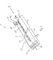
- the in the Fig. 1 to 5 illustrated conveyor 1 of a device according to the invention for conveying products, for example slices or portions, which originate from a high-performance slicer for slicing food products, comprises a carrier 3 and a conveying section 5 held on the carrier 3.
- the carrier 3 and the conveyor section 5 are arranged one behind the other along the conveying direction I, ie the carrier 3 is located in the conveying direction I in front of the conveyor section 5.
- the conveyor section 5 of the conveyor 1 has two sections 9 and 11 which are plate-shaped are and have a roughly rectangular top.
- the two sections 9 and 11 are on a rod-shaped axle member 13 (see. Fig. 4 ) movably mounted in the conveying direction I centrally below the two sections 9, 11 extends.
- the shaft member 13 By means of the shaft member 13, the two sections 9, 11 are held on the carrier 3.
- Each section 9, 11 also has an elongated, central recess 14 (see. Fig. 1 ).
- the conveying section 5 or the two subsections 9, 11 can assume a conveying position relative to the carrier 3, as in FIG Fig. 1 is shown.
- the sections 9, 11 perform a rotational movement about the shaft member 13 and thereby reach a safety position, as in Fig. 2 is shown.
- the conveyor section 5 is thus tiltable relative to the carrier 3 between the conveying position and the safety position about an axis A running in the conveying direction I and defined by the axle element 13.
- the two partial sections 9, 11 can tilt together about the axis A, but can also be tilted about the axis A independently of each other.
- a retaining device 15 in the conveying position between the rear section 9 and the carrier 3, a retaining device 15 is effective (see. Fig. 2 and 4 ), which releases a tilting into the safety position only when a limit load is exceeded.
- the retaining device 15 comprises two elevations 17, which are each arranged laterally offset from the axis A on the carrier 3 and each having a depression 19 in its center.
- spherical locking elements On the side of the portion 9, which is opposite to the carrier 3, two against the conveying direction I biased, spherical locking elements (not shown) are arranged. In this case, the locking elements engage in the conveying position in each case in one of the depressions 19, whereby the section 9 in the conveying position (see. Fig. 1 ) is held.
- the bias acting on the locking elements is selected so that the locking elements are pressed out of the depressions 19 when the section 9 is loaded beyond the limit load.
- the conveyor section 5 can then tilt as a whole relative to the carrier 3 about the axis A and get into the safety position (see. Fig. 2 ).
- a further, second retaining means 21 is provided which is formed in the same manner as the first retaining means 15. By the second retaining means 21, the front portion 11 is held in the conveying position.
- the front portion 11 is further tiltable about a transverse to the conveying direction I second axis B relative to the rear portion 9, so that the front end 23 of the front portion 11 can pivot relative to the rear portion 9 down when one on the rear portion 11th acting limit load is exceeded (see. Fig. 5 ).
- the front portion 11 can be tilted relative to the rear portion 9 also about both axes A, B simultaneously, for example, when a front corner portion of the front portion 11 charged and the limit load is exceeded.
- a deflection device 25 is mounted, by means of the over the entire width of the conveyor 1 offset from one another, in the conveying direction I extending conveyor belt 27 are deflected.
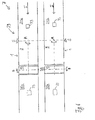
- the conveying device described above comes in the conveying device 7 of Fig. 6 and 7 used, in which two side by side arranged conveyor 1 are used.
- the conveying device 7 has a base 29 which is formed by two parallel input conveyors 31a, 31b, which are arranged, for example, downstream of a slicing machine (not shown) for slicing food, and transport products 33 originating from the slicing machine in the conveying direction I.
- Each input conveyor 31a, 31b is arranged downstream of one of the conveyors 1, in order to further transport the products 33 arriving from the respective input conveyor 31a, 31b.
- Each conveyor 1 is arranged in the manner of a rocker on the respective input conveyor 31a, 31b, so that each conveyor 1 to a transverse to the conveying direction I extending pivot axis S can be pivoted.
- Each of the two conveyors 1 is followed by an output conveyor pair 35a, 35b.
- Each output conveyor pair 35a, 35b has two superimposed output conveyors, namely an upper output conveyor 37a in a plane E1 and a lower output conveyor 37b in an underlying plane E2 (FIG. Fig. 7 ).
- Fig. 7 shows by way of example a situation in which a conveyor 1 is pivoted up to its upper output conveyor 37a and the other conveyor 1 arranged next to it down to its lower output conveyor 37b.
- the products 33 can then be fed via the respective output conveyor 37a, 37b to a device (not shown) downstream of the respective output conveyor 37a, 37b, such as a further conveyor, a robot unit or a packaging machine.
- the sections 9, 11 of the respective conveyor 1 assume a conveying position in which they are held by the retaining devices 15, 21.
- the subsections 9, 11 of the conveyors 1 arranged next to one another can tilt about the respective axis A running in the conveying direction I when a limit load acting on the subsections 9, 11 is exceeded. This can be avoided that an operator is injured, which engages between the two independently pivotable conveyor 1.
- each conveyor 1 since the front portion 11 of each conveyor 1 is tiltable about the axis B transverse to the conveying direction I, the front portion 11 can be independent of the rear portion 9 even then dodge when the operator engages in the area between the currently driven output conveyor 37a or 37b and the rear portion 11, as shown in FIG Fig. 7 is shown on the example of the upwardly pivoted conveyor 1, the tilted in a safety position about the axis B front portion 11 is indicated by dashed lines.
Landscapes
- Engineering & Computer Science (AREA)
- Mechanical Engineering (AREA)
- Structure Of Belt Conveyors (AREA)
- Framework For Endless Conveyors (AREA)
Abstract
Description
- Die vorliegende Erfindung betrifft eine Einrichtung zum Fördern von Produkten, insbesondere von von einer Aufschneidemaschine für Lebensmittelprodukte stammenden Produktscheiben oder Produktportionen.
- Förderanlagen zum Transportieren von Produkten mittels Förderbändern oder dergleichen sind an sich bekannt. Derartige Förderanlagen können zum Beispiel einen Eingangsförderer und mehrere dem Eingangsförderer nachgeordnete, übereinanderliegende Ausgangsförderer aufweisen. Es ist bekannt, einen als Verteiler dienenden Förderer an dem - in Förderrichtung betrachtet - vorderen Ende des Eingangsförderers nach Art einer Wippe vorzusehen, so dass der Förderer verschwenkbar ist, um Produkte, die über den Eingangsförderer einlaufen, in Abhängigkeit von der Schwenkstellung des Förderers einem der nachgeordneten Ausgangsförderer zuzuführen. Da der Förderer ein bewegliches, weil verschwenkbares, Bauteil in der Förderanlage bildet, sind hohe Sicherheitsanforderungen an den Förderer bzw. an die Förderanlage zu stellen.
- Der vorliegenden Erfindung liegt die Aufgabe zugrunde, eine im Hinblick auf die Sicherheitsanforderungen verbesserte Einrichtung zum Fördern von Produkten zu schaffen.
- Die Aufgabe wird durch eine Einrichtung mit den Merkmalen des Anspruchs 1 gelöst.
- Eine Fördereinrichtung der eingangs genannten Art umfasst erfindungsgemäß zumindest einen Förderer, der einen Träger und wenigstens einen am Träger gehaltenen Förderabschnitt umfasst, wobei zumindest ein Teil des Förderabschnitts relativ zum Träger zwischen einer Förderstellung und einer Sicherheitsstellung um eine in Förderrichtung verlaufende Achse verkippbar ist.
- Aufgrund der Verkippbarkeit des Förderabschnitts um die in Förderrichtung verlaufende Achse erfüllt die erfindungsgemäße Fördereinrichtung höhere Sicherheitsanforderungen als aus dem Stand der Technik bekannte Förderanlagen. Insbesondere ist es aufgrund der Verkippbarkeit möglich, dass der Förderabschnitt bzw. ein verkippbarer Teil des Förderabschnitts einem Köperteil einer Bedienperson, wie etwa einer Hand oder einem Arm, ausweichen kann, wenn der Körperteil versehentlich einer durch den bestimmungsgemäßen Betrieb der Einrichtung notwendigen Bewegung des Förderabschnitts, beispielsweise dem eingangs erwähnten Verschwenken, "im Wege ist", d.h. wenn der Körperteil durch eine Unachtsamkeit der Bedienperson in den Bewegungsbereich des Förderabschnitts gelangt. Eine Verletzung der Bedienperson wird somit durch die Erfindung vermieden.
- Besonders vorteilhaft ist die Erfindung in Verbindung mit Fördervorrichtungen, die mehrere unabhängig voneinander bewegbare und in räumlicher Nähe zueinander angeordnete Förderer aufweisen, beispielsweise mehrere nebeneinander liegende, jeweils nach Art einer Wippe verschwenkbare Förderer zum Verteilen von einlaufenden Produkten. In derartigen Situationen ergeben sich nämlich im laufenden Betrieb zwischen den einzelnen Förderern Zwischenräume oder Durchlässe, die eine Bedienperson zu einem Eingreifen bzw. Hindurchgreifen verleiten können, und zwar vor allem dann, wenn - wie in der Praxis häufig der Fall - die einzelnen Bewegungen der Förderer nicht kontinuierlich, sondern nur zeitweise erfolgen. Es sind dann nämlich nur vermeintlich dauerhaft, tatsächlich aber nur vorübergehend auftretende Zwischenräume bzw. Durchlässe vorhanden, die sich bei der nächsten Bewegung eines der Förderer wieder schließen können. Besonders problematisch ist, dass diese diskontinuierlichen Bewegungsabläufe häufig nicht vorhersehbar sind, da sie von zahlreichen Bedingungen abhängig sind, die sich ständig ändern können. Die erfindungsgemäß vorgesehene Verkippbarkeit des Förderabschnitts in eine Sicherheitsstellung kann gerade in derartigen Umgebungen Verletzungen sicher vermeiden, da der Förderabschnitt aufgrund seiner Verkippbarkeit ausweichen kann, wenn er auf einen Widerstand in Form eines versehentlich in seinen Bewegungsbereich gelangten Körperteils stößt.
- Mögliche Weiterbildungen und Ausführungsformen der Erfindung sind auch in den abhängigen Ansprüchen, der Beschreibung sowie den Zeichnungen angegeben.
- Bevorzugt ist eine in der Förderstellung wirksame Rückhalteeinrichtung vorgesehen, die ein Verkippen des Förderabschnitts in die Sicherheitsstellung erst bei Überschreiten einer auf den Förderabschnitt wirkenden Grenzbelastung freigibt. Dadurch wird erreicht, dass der Förderabschnitt während des normalen Förderbetriebs in der Förderstellung gehalten wird und nur in Ausnahmefällen, wenn die Grenzbelastung überschritten wird, in die Sicherheitsstellung verkippt. Dabei ist die Grenzbelastung vorteilhaft so gewählt, dass sie überschritten wird, wenn der Förderabschnitt an einen Körperteil einer Bedienperson stößt.
- Besonders bevorzugt ist die Rückhalteeinrichtung zwischen dem Förderabschnitt und dem Träger wirksam. Auf diese Weise kann die Rückhalteeinrichtung kompakt gehalten und kostengünstig ausgebildet werden. Die Rückhalteeinrichtung kann beispielsweise wenigstens ein vorgespanntes, insbesondere kugelförmiges, Verriegelungselement aufweisen, welches am Förderabschnitt angeordnet und in der Förderstellung in eine Aufnahme eingreift, die komplementär zu dem Verriegelungselement am Träger vorgesehen ist. Dadurch wird der Förderabschnitt am Träger gehalten. Bei Überschreiten der Grenzbelastung gelangt das Verriegelungselement entgegen seiner Vorspannung außer Eingriff mit der Aufnahme, so dass der Förderabschnitt freigeben wird und in die Sicherheitsstellung verkippen kann.
- Der Träger kann in Förderrichtung betrachtet vor dem Förderabschnitt angeordnet sein, so dass der Träger und der Förderabschnitt in Förderrichtung betrachtet hintereinander liegen.
- Bevorzugt ist der Förderabschnitt, insbesondere mittig, auf einem die Achse definierenden, insbesondere stabförmigen, sich in Förderrichtung erstreckenden Achselement gelagert und/oder mittels des Achselements am Träger getragen. Durch Verwendung des Achselements zur Kopplung des Förderabschnitts mit dem Träger kann auf einfache Weise die Verkippbarkeit des Förderabschnitts relativ zum Träger erreicht werden.
- Vorzugsweise umfasst der Förderabschnitt wenigsten einen plattenförmig ausgebildeten Teilabschnitt, der insbesondere eine tischartige Auflagefläche bzw. einen Unterbau für ein darüber laufendes Förderband oder für mehrere darüber laufende, parallele Förderriemen des Förderers bilden kann.
- Nach einer bevorzugten Weiterbildung der Erfindung ist der Förderabschnitt oder ein Teilabschnitt des Förderabschnitts zwischen der Förderstellung und einer weiteren, zweiten Sicherheitsstellung um eine quer zur Förderrichtung verlaufende, zweite Achse verkippbar. Dadurch wird eine weitere Ausweichmöglichkeit für den Förderabschnitt geschaffen.
- Besonders bevorzugt weist der Förderabschnitt wenigstens zwei in Förderrichtung hintereinander liegende Teilabschnitte auf, wobei der in Förderrichtung betrachtet vordere Teilabschnitt zwischen der Förderstellung und der weiteren, zweiten Sicherheitsstellung um die zweite Achse verkippbar ist. Der vordere, insbesondere weiter vom Träger entfernt liegende Teilabschnitt kann somit nicht nur um die in Förderrichtung verlaufende Achse verkippen, sondern auch um die quer dazu verlaufende zweite Achse. Dadurch kann der vordere Teilabschnitt beispielsweise ausweichen, wenn eine Bedienperson in einen Bereich zwischen dem vorderen Teilabschnitt und einem nachgeordneten Förderer greift. Es kann somit vermieden werden, dass die Hand oder der Arm einer Bedienperson zwischen dem vorderen Teilabschnitt und dem nachgeordneten Förderer eingeklemmt wird.
- Es ist zweckmäßig, aber nicht zwingend, dass der vordere Teilabschnitt um beide Achsen verkippbar ist. So kann allgemein vorgesehen sein, dass der Förderabschnitt mehrere Teilabschnitte aufweist, von denen nicht alle um die in Förderrichtung verlaufende Achse verkippbar sind, sondern wenigstens ein Teilabschnitt lediglich um die quer zur Förderrichtung laufende Achse verkippbar ist.
- In der Förderstellung kann eine weitere, zweite Rückhalteeinrichtung zwischen den beiden Teilabschnitten wirksam sein, die ein Verkippen des vorderen Teilabschnitts in die zweite Sicherheitsstellung erst bei Überschreiten einer auf den vorderen Teilabschnitt wirkenden Grenzbelastung freigibt.
- Generell kann auch unabhängig von den vorstehend erläuterten Ausgestaltungen bei einem mehrteiligen Förderabschnitt vorgesehen sein, dass die einzelnen Teile unabhängig voneinander und relativ zueinander bzw. relativ zu einem Träger bzw. einer Basis, zwischen einer Förderstellung und einer Sicherheitsstellung verstellbar bzw. verkippbar sind.
- Gemäß einem Ausführungsbeispiel ist vorgesehen, dass der Förderabschnitt ein umlaufendes Förderband oder umlaufende Förderriemen umfasst, das bzw. die bei einem Verkippen eines Teils eines mehrteiligen Förderabschnitts selbst nicht oder zumindest nicht als Ganzes verkippt wird bzw. werden, aber derart angeordnet und/oder ausgebildet ist bzw. sind, dass das Verkippen des Teils des Förderabschnitts möglich ist. Dabei kann insbesondere in Förderrichtung betrachtet hinter dem Förderabschnitt wenigstens eine Umlenkeinrichtung für das Förderband oder für die Förderriemen vorgesehen sein, wobei bevorzugt die Umlenkeinrichtung am Förderabschnitt festgelegt ist. Insbesondere verläuft die Achse, um welche das Teil verkippbar ist, zwischen Obertrum und Untertrum des Förderbandes bzw. zwischen Obertrumen und Untertrumen der Förderriemen.
- Hierdurch wird auf in konstruktiver Hinsicht einfache Weise erreicht, dass bei einem mehrteiligen Förderabschnitt nicht alle Teile gemeinsam verkippen müssen.
- Auch dann, wenn der Förderabschnitt als Ganzes verkippt wird bzw. wenn alle Teile eines mehrteiligen Förderabschnitts gemeinsam verkippt werden, ist ein Förderband bzw. sind Förderriemen bei entsprechender Anordnung und/oder Ausbildung vorteilhaft, da es auf diese Weise möglich ist, nur eine Umlenkung am Förderabschnitts selbst und die andere Umlenkung an einer Basis vorzusehen, an welcher der Förderabschnitt angebracht ist und relativ zu welcher das Verkippen des Förderabschnitts erfolgt.
- Vorzugsweise ist in Förderrichtung betrachtet hinter dem Förderabschnitt wenigstens eine Umlenkeinrichtung für das Förderband bzw. für die Förderriemen vorgesehen.
- Bevorzugt ist die Umlenkeinrichtung am Förderabschnitt, insbesondere an einem in Förderrichtung betrachtet vorderen Teil des Förderabschnitts, befestigt. Die Umlenkeinrichtung wird daher mitbewegt, wenn der Förderabschnitt bzw. der vordere Teil des Förderabschnitts verkippt wird, so dass auch ein über die Umlenkeinrichtung laufendes Förderband bzw. über die Umlenkeinrichtung laufende Förderriemen verkippt wird bzw. werden.
- Nach einer bevorzugten Weiterbildung der Erfindung ist der Förderer dazu ausgebildet, an einer Basis angebracht und relativ zur Basis um eine quer zur Förderrichtung verlaufende Schwenkachse verschwenkt zu werden. Der Förderer lässt sich somit beispielsweise nach Art einer zum Verteilen von einlaufenden Produkten auf nachfolgende, übereinander angeordnete Ausgangsförderer dienenden Wippe an der Basis anbringen.
- Vorzugsweise kann der Förderer in Abhängigkeit von der Schwenkstellung mit einem von mehreren übereinander angeordneten Ausgangs- oder Eingangsförderern zur Übergabe oder Übernahme von Produkten zusammenwirken.
- Der Förderer kann beispielsweise an dem in Förderrichtung betrachtet vorderen Ende eines Eingangsförderers angeordnet sein, um über den Eingangsförderer einlaufende Produkte in Abhängigkeit von der Schwenkstellung des Förderers einem der nachgeordneten Ausgangsförderer zuzuführen. Umgekehrt kann der Förderer auch an dem in Förderrichtung betrachtet hinteren Ende eines Ausgangsförderers angeordnet sein, um Produkte, die von einem von mehreren übereinander angeordneten Eingangsförderern einlaufen, dem Ausgangsförderer zuzuführen. Der Förderer kann somit als eine Art Weiche eingesetzt werden.
- Vorzugsweise ist der Träger zur verschwenkbaren Anbringung des Förderers an der Basis ausgebildet.
- An der Basis kann eine weitere, insbesondere angetriebene, Umlenkeinrichtung vorgesehen sein, um zwischen der vorstehend erwähnten ersten Umlenkeinrichtung des Förderabschnitts und der zweiten Umlenkeinrichtung ein Förderband oder mehrere parallele Förderriemen einspannen zu können.
- Die Erfindung betrifft auch eine Fördervorrichtung mit einer Basis und zumindest einer erfindungsgemäßen Fördereinrichtung, wobei der Förderer der Fördereinrichtung an der Basis angebracht und relativ zur Basis um eine quer zur Förderrichtung verlaufende Achse verschwenkbar ist.
- Bei einer bevorzugten Ausgestaltung der Fördervorrichtung sind mehrere Förderer vorgesehen, die nebeneinander an der Basis angeordnet und unabhängig voneinander verschwenkbar sind. Beispielsweise können zumindest zwei nebeneinander liegende Eingangsförderer vorgesehen sein, denen jeweils ein Förderer nachgeordnet ist, der nach Art einer Wippe verschwenkbar ist. Da jeder Förderer in eine Sicherheitsstellung verkippbar ist, können die Förderer ausweichen, falls eine Bedienperson zwischen die Förderer greift und die Förderer relativ zueinander verschwenkt werden.
- Die Erfindung wird nachfolgend beispielhaft anhand der beigefügten Zeichnungen erläutert. Es zeigen, jeweils in schematischer Darstellung,
- Fig. 1
- eine perspektivische Darstellung eines erfindungsgemäßen Förderers, dessen Förderabschnitt sich relativ zu einem Träger des Förderers in einer Förderstellung befindet,
- Fig. 2
- eine weitere perspektivische Darstellung des Förderers von
Fig. 1 , bei dem sich der Förderabschnitt relativ zum Träger in einer Sicherheitsstellung befindet, - Fig. 3
- eine weitere perspektivische Darstellung des Förderers von
Fig. 1 , wobei ein in Förderrichtung betrachtet vorderer Teilabschnitt des Förderabschnitts relativ zu einem hinteren Teilabschnitt eine Sicherheitsstellung einnimmt, - Fig. 4
- eine perspektivische Darstellung der Unterseite des Förderers von
Fig. 1 , bei dem sich der Förderabschnitt relativ zum Träger in einer Sicherheitsstellung befindet, - Fig. 5
- eine weitere perspektivische Darstellung der Unterseite des Förderers von
Fig. 1 , wobei der in Förderrichtung betrachtet vordere Teilabschnitt des Förderabschnitts relativ zu dem hinteren Teilabschnitt eine Sicherheitsstellung einnimmt und der hintere Teilabschnitt eine Sicherheitsstellung relativ zum Träger einnimmt, - Fig. 6
- eine Draufsicht auf eine erfindungsgemäße Fördervorrichtung, und
- Fig. 7
- eine seitliche Ansicht der Fördervorrichtung von
Fig. 6 . - Der in den
Fig. 1 bis 5 dargestellte Förderer 1 einer erfindungsgemäßen Einrichtung zum Fördern von Produkten, beispielsweise Scheiben oder Portionen, die von einem Hochleistungsslicer zum Aufschneiden von Lebensmittelprodukten stammen, umfasst einen Träger 3 und einen am Träger 3 gehaltenen Förderabschnitt 5. - Bei dem Förderer 1 sind der Träger 3 und der Förderabschnitt 5 längs der Förderrichtung I hintereinander angeordnet, d.h. der Träger 3 liegt in Förderrichtung I betrachtet vor dem Förderabschnitt 5. Der Förderabschnitt 5 des Förderers 1 weist zwei Teilabschnitte 9 und 11 auf, die plattenförmig ausgebildet sind und eine in etwa rechteckige Oberseite besitzen. Die beiden Teilabschnitte 9 und 11 sind auf einem stabförmigen Achselement 13 (vgl.
Fig. 4 ) beweglich gelagert, das in Förderrichtung I mittig unterhalb der beiden Teilabschnitte 9, 11 verläuft. Mittels des Achselements 13 werden die beiden Teilabschnitte 9, 11 am Träger 3 gehalten. Jeder Teilabschnitt 9, 11 weist außerdem eine längliche, mittige Aussparung 14 auf (vgl.Fig. 1 ). - Der Förderabschnitt 5 bzw. die beiden Teilabschnitte 9, 11 können relativ zum Träger 3 eine Förderstellung einnehmen, wie in
Fig. 1 gezeigt ist. Außerdem können die Teilabschnitte 9, 11 eine Drehbewegung um das Achselement 13 ausführen und dadurch in eine Sicherheitsstellung gelangen, wie inFig. 2 gezeigt ist. Bei dem Förderer 1 ist somit der Förderabschnitt 5 relativ zum Träger 3 zwischen der Förderstellung und der Sicherheitsstellung um eine in Förderrichtung I verlaufende, vom Achselement 13 definierte Achse A verkippbar. Die beiden Teilabschnitt 9, 11 können gemeinsam um die Achse A kippen, aber auch unabhängig voneinander um die Achse A verkippt werden. - Dabei ist in der Förderstellung zwischen dem hinteren Teilabschnitt 9 und dem Träger 3 eine Rückhalteinrichtung 15 wirksam (vgl.
Fig. 2 und4 ), die ein Verkippen in die Sicherheitsstellung erst bei Überschreiten einer Grenzbelastung freigibt. Die Rückhalteeinrichtung 15 umfasst zwei Hervorhebungen 17, die jeweils seitlich versetzt zur Achse A am Träger 3 angeordnet sind und in ihrer Mitte jeweils eine Einsenkung 19 aufweisen. An der Seite des Teilabschnitts 9, die dem Träger 3 gegenüberliegt, sind zwei gegen die Förderrichtung I vorgespannte, kugelförmige Verriegelungselemente (nicht gezeigt) angeordnet. Dabei greifen die Verriegelungselemente in der Förderstellung jeweils in eine der Einsenkungen 19 ein, wodurch der Teilabschnitt 9 in der Förderstellung (vgl.Fig. 1 ) gehalten wird. Die auf die Verriegelungselemente wirkende Vorspannung ist so gewählt, dass die Verriegelungselemente aus den Einsenkungen 19 gedrückt werden, wenn der Teilabschnitt 9 über die Grenzbelastung hinaus belastet wird. Der Förderabschnitt 5 kann dann als Ganzes relativ zum Träger 3 um die Achse A kippen und in die Sicherheitsstellung gelangen (vgl.Fig. 2 ). - Zwischen dem hinteren Teilabschnitt 9 und dem vorderen Teilabschnitt 11 ist eine weitere, zweite Rückhalteeinrichtung 21 vorgesehen, die in der gleichen Weise wie die erste Rückhalteeinrichtung 15 ausgebildet ist. Durch die zweite Rückhalteeinrichtung 21 wird der vordere Teilabschnitt 11 in der Förderstellung gehalten.
- Der vordere Teilabschnitt 11 ist ferner um eine quer zur Förderrichtung I verlaufende zweite Achse B relativ zum hinteren Teilabschnitt 9 verkippbar, so dass das vordere Ende 23 des vorderen Teilabschnitts 11 relativ zum hinteren Teilabschnitt 9 nach unten verschwenken kann, wenn eine auf den hinteren Teilabschnitt 11 wirkende Grenzbelastung überschritten wird (vgl.
Fig. 5 ). - Wie
Fig. 3 zeigt, kann der vordere Teilabschnitt 11 relativ zum hinteren Teilabschnitt 9 auch um beide Achsen A, B gleichzeitig gekippt werden, wenn beispielsweise ein vorderer Eckbereich des vorderen Teilabschnitts 11 belastet und die Grenzlast überschritten wird. - Am vorderen Ende 23 des vorderen Teilabschnitts 11 ist eine Umlenkeinrichtung 25 angebracht, mittels der über die gesamte Breite des Förderers 1 versetzt zueinander angeordnete, in Förderrichtung I verlaufende Förderriemen 27 umgelenkt werden.
- Die vorstehend beschriebene Fördereinrichtung kommt in der Fördervorrichtung 7 der
Fig. 6 und7 zum Einsatz, in welcher zwei nebeneinander angeordnete Förderer 1 verwendet werden. - Dabei weist die Fördervorrichtung 7 eine Basis 29 auf, die von zwei parallelen Eingangsförderern 31a, 31b gebildet ist, welche beispielsweise einer Aufschneidemaschine (nicht gezeigt) zum Aufschneiden von Lebensmitteln nachgeordnet sind und von der Aufschneidemaschine stammende Produkte 33 in Förderrichtung I herantransportieren. Jedem Eingangsförderer 31 a, 31b ist einer der Förderer 1 nachgeordnet, um die von dem jeweiligen Eingangsförderer 31a, 31b einlaufenden Produkte 33 weiter zu transportieren. Dabei ist jeder Förderer 1 nach Art einer Wippe an dem jeweiligen Eingangsförderer 31a, 31b angeordnet, so dass jeder Förderer 1 um eine quer zur Förderrichtung I verlaufende Schwenkachse S verschwenkt werden kann.
- Den beiden Förderern 1 nachgeordnet ist jeweils ein Ausgangsfördererpaar 35a, 35b. Jedes Ausgangsfördererpaar 35a, 35b weist zwei übereinander angeordnete Ausgangsförderer auf, und zwar einen oberen Ausgangsförderer 37a in einer Ebene E1 und einen unteren Ausgangsförderer 37b in einer darunter liegenden Ebene E2 (
Fig. 7 ). -
Fig. 7 zeigt beispielhaft eine Situation, in welcher ein Förderer 1 nach oben zu seinem oberen Ausgangsförderer 37a und der daneben angeordnete andere Förderer 1 nach unten zu seinem unteren Ausgangsförderer 37b geschwenkt ist. Über den jeweiligen Ausgangsförderer 37a, 37b können die Produkte 33 sodann einer dem jeweiligen Ausgangsförderer 37a, 37b nachgeordneten Einrichtung (nicht gezeigt), wie etwa einer weiteren Fördereinrichtung, einer Robotereinheit oder einer Verpackungsmaschine, zugeführt werden. - Wie vorstehend erwähnt ist, nehmen die Teilabschnitte 9, 11 des jeweiligen Förderers 1 eine Förderstellung ein, in der sie durch die Rückhalteeinrichtungen 15, 21 gehalten werden. Die Teilabschnitte 9, 11 der nebeneinander angeordneten Förderer 1 können bei Überschreitung einer auf die Teilabschnitte 9, 11 wirkenden Grenzbelastung um die jeweilige in Förderrichtung I verlaufende Achse A verkippen. Dadurch kann vermieden werden, dass eine Bedienperson verletzt wird, die zwischen die beiden unabhängig voneinander verschwenkbaren Förderer 1 greift.
- Da der vordere Teilabschnitt 11 jedes Förderers 1 außerdem um die quer zur Förderrichtung I verlaufende Achse B verkippbar ist, kann der vordere Teilabschnitt 11 unabhängig von dem hinteren Teilabschnitt 9 auch dann ausweichen, wenn die Bedienperson in den Bereich zwischen den jeweils gerade angesteuerten Ausgangsförderer 37a bzw. 37b und den hinteren Teilabschnitt 11 greift, wie es in
Fig. 7 am Beispiel des nach oben geschwenkten Förderers 1 dargestellt ist, dessen in eine Sicherheitsstellung um die Achse B verkippter vorderer Teilabschnitt 11 gestrichelt angedeutet ist. -
- 1
- Förderer
- 3
- Träger
- 5
- Förderabschnitt
- 7
- Fördervorrichtung
- 9
- Teilabschnitt
- 11
- Teilabschnitt
- 13
- Achselement
- 14
- Aussparung
- 15
- Rückhalteeinrichtung
- 17
- Hervorhebung
- 19
- Einsenkung
- 21
- Rückhalteeinrichtung
- 23
- vorderes Ende
- 25
- Umlenkeinrichtung
- 27
- Förderriemen
- 29
- Basis
- 31a
- Eingangsförderer
- 31b
- Eingangsförderer
- 33
- Produkt
- 35a
- Ausgangsförderer
- 35b
- Ausgangsförderer
- 37a
- oberer Ausgangsförderer
- 37b
- unterer Ausgangsförderer
- A
- Achse
- B
- Achse
- I
- Förderrichtung
- S
- Schwenkachse
- E1
- Ebene
- E2
- Ebene
Claims (15)
- Einrichtung zum Fördern von Produkten (33), insbesondere von von einer Aufschneidemaschine für Lebensmittelprodukte stammenden Produktscheiben oder Produktportionen,
mit zumindest einem Förderer (1), der einen Träger (3) und wenigstens einen am Träger (3) gehaltenen Förderabschnitt (5) umfasst, wobei zumindest ein Teil des Förderabschnitts (5) relativ zum Träger (3) zwischen einer Förderstellung und einer Sicherheitsstellung um eine in Förderrichtung (I) verlaufende Achse (A) verkippbar ist. - Einrichtung nach Anspruch 1,
dadurch gekennzeichnet, dass eine in der Förderstellung wirksame Rückhalteeinrichtung (15) vorgesehen ist, die ein Verkippen des Förderabschnitts (5) in die Sicherheitsstellung erst bei Überschreiten einer auf den Förderabschnitt (5) wirkenden Grenzbelastung freigibt. - Einrichtung nach Anspruch 2,
dadurch gekennzeichnet, dass die Rückhalteeinrichtung (15) zwischen dem Förderabschnitt (5) und dem Träger (3) wirksam ist. - Einrichtung nach einem der vorhergehenden Ansprüche,
dadurch gekennzeichnet, dass der, insbesondere als vorzugsweise U-förmiger Bügel ausgebildete, Träger (3) in Förderrichtung (I) betrachtet vor dem Förderabschnitt (5) angeordnet ist. - Einrichtung nach einem der vorhergehenden Ansprüche,
dadurch gekennzeichnet, dass der Förderabschnitt (5), insbesondere mittig, auf einem die Achse (A) definierenden Achselement (13) gelagert und/oder mittels des Achselements (13) am Träger (3) getragen ist. - Einrichtung nach einem der vorhergehenden Ansprüche,
dadurch gekennzeichnet, dass der Förderabschnitt (5) wenigsten einen plattenförmig ausgebildeten Teilabschnitt (9, 11) aufweist. - Einrichtung nach einem der vorhergehenden Ansprüche,
dadurch gekennzeichnet, dass der Förderabschnitt (5) oder ein Teilabschnitt (11) des Förderabschnitts (5) zwischen der Förderstellung und einer weiteren, zweiten Sicherheitsstellung um eine quer zur Förderrichtung (I) verlaufende zweite Achse (B) verkippbar ist. - Einrichtung nach Anspruch 7,
dadurch gekennzeichnet, dass der Förderabschnitt (5) wenigstens zwei in Förderrichtung (I) hintereinander liegende Teilabschnitte (9, 11) aufweist, wobei der in Förderrichtung (I) betrachtet vordere Teilabschnitt (11) zwischen der Förderstellung und der weiteren, zweiten Sicherheitsstellung um die zweite Achse (B) verkippbar ist. - Einrichtung nach Anspruch 8,
dadurch gekennzeichnet, dass in der Förderstellung eine weitere, zweite Rückhalteeinrichtung (21) zwischen den beiden Teilabschnitten (9, 11) wirksam ist, wobei die zweite Rückhalteeinrichtung (21) ein Verkippen des vorderen Teilabschnitts (11) in die zweite Sicherheitsstellung erst bei Überschreiten einer auf den hinteren Teilabschnitt (11) wirkenden Grenzbelastung freigibt. - Einrichtung nach einem der vorhergehenden Ansprüche,
dadurch gekennzeichnet, dass der Förderabschnitt (5) ein umlaufendes Förderband oder umlaufende Förderriemen (27) umfasst, das bzw. die bei einem Verkippen eines Teils (9, 11) eines mehrteiligen Förderabschnitts (5) selbst nicht oder zumindest nicht als Ganzes verkippt wird bzw. werden. - Einrichtung nach einem der vorhergehenden Ansprüche,
dadurch gekennzeichnet, dass der Förderer (1) dazu ausgebildet ist, an einer Basis (29) angebracht und relativ zur Basis (29) um eine quer zur Förderrichtung (I) verlaufende Schwenkachse (S) verschwenkt zu werden, insbesondere um in Abhängigkeit von der Schwenkstellung mit einem von mehreren übereinander angeordneten Ausgangs- oder Eingangsförderern (31a, 31b, 37a, 37b) zur Übergabe oder Übernahme von Produkten (33) zusammenzuwirken. - Einrichtung nach Anspruch 11,
dadurch gekennzeichnet, dass der Träger (3) zur verschwenkbaren Anbringung des Förderers (1) an der Basis (29) ausgebildet ist. - Einrichtung nach Anspruch 11 oder 12,
dadurch gekennzeichnet, dass zwischen der Basis (29) und einer Umlenkeinrichtung (25) ein umlaufendes Förderband oder umlaufende Förderriemen (27) eingespannt sind, wobei insbesondere eine Spannvorrichtung vorgesehen ist, mittels welcher die Zugspannung im Förderband bzw. in den Förderriemen (27) veränderbar ist. - Fördervorrichtung mit einer Basis (29) und zumindest einer Fördereinrichtung nach einem der vorhergehenden Ansprüche,
wobei der Förderer (1) an der Basis (29) angebracht und zumindest teilweise relativ zur Basis (29) um eine quer zur Förderrichtung (I) verlaufende Achse (S) verschwenkbar ist. - Fördervorrichtung nach Anspruch 14,
dadurch gekennzeichnet, dass die Fördereinrichtung mehrere Förderer (1) umfasst, die nebeneinander an der Basis (29) angeordnet und unabhängig voneinander verschwenkbar sind.
Applications Claiming Priority (1)
| Application Number | Priority Date | Filing Date | Title |
|---|---|---|---|
| DE102012001770A DE102012001770A1 (de) | 2012-01-31 | 2012-01-31 | Einrichtung zum Fördern von Produkten |
Publications (2)
| Publication Number | Publication Date |
|---|---|
| EP2623442A1 true EP2623442A1 (de) | 2013-08-07 |
| EP2623442B1 EP2623442B1 (de) | 2015-02-11 |
Family
ID=47623831
Family Applications (1)
| Application Number | Title | Priority Date | Filing Date |
|---|---|---|---|
| EP12197113.9A Active EP2623442B1 (de) | 2012-01-31 | 2012-12-14 | Einrichtung zum Fördern von Produkten |
Country Status (3)
| Country | Link |
|---|---|
| US (1) | US9327909B2 (de) |
| EP (1) | EP2623442B1 (de) |
| DE (1) | DE102012001770A1 (de) |
Families Citing this family (2)
| Publication number | Priority date | Publication date | Assignee | Title |
|---|---|---|---|---|
| DE102012010802A1 (de) | 2012-06-01 | 2013-12-05 | GEA CFS Bühl GmbH | Transportvorrichtung mit einer Magnetkupplung |
| DE102021134049B4 (de) * | 2021-12-21 | 2024-02-29 | Weber Maschinenbau Gmbh Breidenbach | System zum Verarbeiten von Lebensmittelprodukten |
Citations (3)
| Publication number | Priority date | Publication date | Assignee | Title |
|---|---|---|---|---|
| US5857555A (en) * | 1995-02-10 | 1999-01-12 | Grapha-Holding Ag | Actuating device for tilting a structural component |
| US6152280A (en) * | 1997-12-23 | 2000-11-28 | Crisplant A/S | Articulated conveyor |
| US6736254B1 (en) * | 2002-05-14 | 2004-05-18 | Mantissa Corporation | Off-set block tilt tray sorter with gap detector |
Family Cites Families (11)
| Publication number | Priority date | Publication date | Assignee | Title |
|---|---|---|---|---|
| US3717087A (en) * | 1970-11-27 | 1973-02-20 | J Amori | Peach feeding and slicing means |
| DE2260718C3 (de) * | 1971-12-23 | 1981-10-22 | Djačkov, Vladimir K., Moskva | Kurvengängiger Bandförderer |
| DK167274B1 (da) * | 1991-06-18 | 1993-10-04 | Cosan Crisplant As | Fremgangsmaade til destinationssortering og lejlighedsvis mellemlagring af stykgods, f.eks. flybagage, samt sorterings- og lagringsanlaeg til udoevelse af fremgangsmaaden og baerebakke til brug i dette anlaeg |
| IT1263944B (it) * | 1993-02-19 | 1996-09-05 | Macchina smistatrice con dispositivi atti a mantenere in posizione orizzontale i piani di trasporto degli oggetti | |
| AT405396B (de) * | 1997-04-08 | 1999-07-26 | Doppelmayr & Sohn | Förderanlage zum transport von gütern |
| DE19835322C2 (de) * | 1998-08-05 | 2000-07-27 | Sim Zufuehr Und Montagetechnik | Vorrichtung zur Übergabe von auf einer Transporteinrichtung herangeführten Werkstückträgern auf ein paralleles, in entgegengesetzter Förderrichtung arbeitendes Transportband |
| JP4811974B2 (ja) * | 2001-05-11 | 2011-11-09 | 株式会社イシダ | 物品の振分装置 |
| NL1026137C2 (nl) * | 2004-05-07 | 2005-11-08 | Vanderlande Ind Nederland | Inrichting voor het sorteren van producten. |
| US7128217B2 (en) * | 2004-08-11 | 2006-10-31 | The Henry Group, Inc. | Bun laner |
| ITBO20050425A1 (it) * | 2005-06-28 | 2006-12-29 | Unitec Srl | Impianto per il trasporto e la selezione di prodotti ortofrutticoli |
| DE202006011139U1 (de) * | 2006-07-19 | 2006-10-12 | Schwarz, Roland | Einschnitt-Flexible Führungsprofilkomponente (horizontal, vertikal, axial) |
-
2012
- 2012-01-31 DE DE102012001770A patent/DE102012001770A1/de not_active Withdrawn
- 2012-12-14 EP EP12197113.9A patent/EP2623442B1/de active Active
-
2013
- 2013-01-31 US US13/755,459 patent/US9327909B2/en not_active Expired - Fee Related
Patent Citations (3)
| Publication number | Priority date | Publication date | Assignee | Title |
|---|---|---|---|---|
| US5857555A (en) * | 1995-02-10 | 1999-01-12 | Grapha-Holding Ag | Actuating device for tilting a structural component |
| US6152280A (en) * | 1997-12-23 | 2000-11-28 | Crisplant A/S | Articulated conveyor |
| US6736254B1 (en) * | 2002-05-14 | 2004-05-18 | Mantissa Corporation | Off-set block tilt tray sorter with gap detector |
Also Published As
| Publication number | Publication date |
|---|---|
| DE102012001770A1 (de) | 2013-08-01 |
| EP2623442B1 (de) | 2015-02-11 |
| US20130192955A1 (en) | 2013-08-01 |
| US9327909B2 (en) | 2016-05-03 |
Similar Documents
| Publication | Publication Date | Title |
|---|---|---|
| EP2364936B1 (de) | Vorrichtung und Verfahren zum Verteilen von Artikeln innerhalb eines Artikelstroms | |
| DE60118948T2 (de) | Überführung von gegenständen zwischen entgegengesetzt angetriebenen förderern | |
| EP3566980B1 (de) | Formatteil zum umlenken von behältern | |
| DE202012013047U1 (de) | Vorrichtung zum Sammeln von Produkten sowie Anlage mit einer solchen Vorrichtung | |
| WO1998028190A1 (de) | Vorrichtung zum handhaben von gegenständen | |
| EP2428471B1 (de) | Fördersystem | |
| EP2921435A1 (de) | Umlenkvorrichtung für Gegenstände und Verfahren zum Umlenken von Gegenständen | |
| DE10301178A1 (de) | Vorrichtung zum Ausrichten und Verteilen | |
| EP2623442B1 (de) | Einrichtung zum Fördern von Produkten | |
| DE3439966C2 (de) | Transportvorrichtung für Stückgüter oder dergleichen | |
| EP1115638A1 (de) | Verteilvorrichtung für stückgut | |
| WO2017045905A1 (de) | Fördervorrichtung zum fördern von transportstrukturen | |
| EP2743193A1 (de) | Verfahren und Vorrichtung zum Falten oder Wenden einer Scheibe oder einer Portion eines aufgeschnittenen Lebensmittelprodukts | |
| DE602004012046T3 (de) | Vorrichtung zur Verbindung einer Verpackungsmaschine, insbesondere einer Blisterherstellungsmaschine, mit einem Zuführförderer für eine Einschachtelmaschine | |
| DE69521677T2 (de) | Weiche für Förderer | |
| EP2923955B1 (de) | Vorrichtung zur verarbeitung von lebensmittelprodukten | |
| EP2583922B1 (de) | Bandanleger mit abklappbarer Vereinzelungsanordnung | |
| EP3263493A1 (de) | Durchlaufregal zum kommissionieren von lagereinheiten | |
| DE102005029398A1 (de) | Lastaufnahme- und -transportmittel | |
| DE20104371U1 (de) | Förderband mit Stollen | |
| EP1342402A1 (de) | Verfahren und Vorrichtung zur Verstellung von Führungsblechen | |
| EP3515847A1 (de) | Vorrichtung zum zuführen einer mehrzahl flächig aneinander anliegender, flächiger elementen, insbesondere kartonzuschnitten, zu einer verpackungsvorrichtung | |
| DE102010023584A1 (de) | Vorrichtung für die Weitergabe von abgeschnittenen Schneidgutscheiben sowie Schneidgutverarbeitungsanlage mit einer derartigen Vorrichtung | |
| WO2018103900A1 (de) | Transportvorrichtung | |
| DE1556703C (de) | Fahrbarer Höhenförderer |
Legal Events
| Date | Code | Title | Description |
|---|---|---|---|
| PUAI | Public reference made under article 153(3) epc to a published international application that has entered the european phase |
Free format text: ORIGINAL CODE: 0009012 |
|
| AK | Designated contracting states |
Kind code of ref document: A1 Designated state(s): AL AT BE BG CH CY CZ DE DK EE ES FI FR GB GR HR HU IE IS IT LI LT LU LV MC MK MT NL NO PL PT RO RS SE SI SK SM TR |
|
| AX | Request for extension of the european patent |
Extension state: BA ME |
|
| 17P | Request for examination filed |
Effective date: 20130923 |
|
| RBV | Designated contracting states (corrected) |
Designated state(s): AL AT BE BG CH CY CZ DE DK EE ES FI FR GB GR HR HU IE IS IT LI LT LU LV MC MK MT NL NO PL PT RO RS SE SI SK SM TR |
|
| GRAP | Despatch of communication of intention to grant a patent |
Free format text: ORIGINAL CODE: EPIDOSNIGR1 |
|
| INTG | Intention to grant announced |
Effective date: 20140723 |
|
| GRAS | Grant fee paid |
Free format text: ORIGINAL CODE: EPIDOSNIGR3 |
|
| GRAA | (expected) grant |
Free format text: ORIGINAL CODE: 0009210 |
|
| AK | Designated contracting states |
Kind code of ref document: B1 Designated state(s): AL AT BE BG CH CY CZ DE DK EE ES FI FR GB GR HR HU IE IS IT LI LT LU LV MC MK MT NL NO PL PT RO RS SE SI SK SM TR |
|
| REG | Reference to a national code |
Ref country code: GB Ref legal event code: FG4D Free format text: NOT ENGLISH |
|
| REG | Reference to a national code |
Ref country code: CH Ref legal event code: EP |
|
| REG | Reference to a national code |
Ref country code: IE Ref legal event code: FG4D Free format text: LANGUAGE OF EP DOCUMENT: GERMAN |
|
| REG | Reference to a national code |
Ref country code: AT Ref legal event code: REF Ref document number: 709836 Country of ref document: AT Kind code of ref document: T Effective date: 20150315 |
|
| REG | Reference to a national code |
Ref country code: DE Ref legal event code: R096 Ref document number: 502012002254 Country of ref document: DE Effective date: 20150326 |
|
| REG | Reference to a national code |
Ref country code: NL Ref legal event code: T3 |
|
| REG | Reference to a national code |
Ref country code: NL Ref legal event code: T3 |
|
| REG | Reference to a national code |
Ref country code: NL Ref legal event code: T3 |
|
| REG | Reference to a national code |
Ref country code: LT Ref legal event code: MG4D |
|
| PG25 | Lapsed in a contracting state [announced via postgrant information from national office to epo] |
Ref country code: HR Free format text: LAPSE BECAUSE OF FAILURE TO SUBMIT A TRANSLATION OF THE DESCRIPTION OR TO PAY THE FEE WITHIN THE PRESCRIBED TIME-LIMIT Effective date: 20150211 Ref country code: LT Free format text: LAPSE BECAUSE OF FAILURE TO SUBMIT A TRANSLATION OF THE DESCRIPTION OR TO PAY THE FEE WITHIN THE PRESCRIBED TIME-LIMIT Effective date: 20150211 Ref country code: FI Free format text: LAPSE BECAUSE OF FAILURE TO SUBMIT A TRANSLATION OF THE DESCRIPTION OR TO PAY THE FEE WITHIN THE PRESCRIBED TIME-LIMIT Effective date: 20150211 Ref country code: SE Free format text: LAPSE BECAUSE OF FAILURE TO SUBMIT A TRANSLATION OF THE DESCRIPTION OR TO PAY THE FEE WITHIN THE PRESCRIBED TIME-LIMIT Effective date: 20150211 Ref country code: ES Free format text: LAPSE BECAUSE OF FAILURE TO SUBMIT A TRANSLATION OF THE DESCRIPTION OR TO PAY THE FEE WITHIN THE PRESCRIBED TIME-LIMIT Effective date: 20150211 Ref country code: NO Free format text: LAPSE BECAUSE OF FAILURE TO SUBMIT A TRANSLATION OF THE DESCRIPTION OR TO PAY THE FEE WITHIN THE PRESCRIBED TIME-LIMIT Effective date: 20150511 |
|
| PG25 | Lapsed in a contracting state [announced via postgrant information from national office to epo] |
Ref country code: GR Free format text: LAPSE BECAUSE OF FAILURE TO SUBMIT A TRANSLATION OF THE DESCRIPTION OR TO PAY THE FEE WITHIN THE PRESCRIBED TIME-LIMIT Effective date: 20150512 Ref country code: RS Free format text: LAPSE BECAUSE OF FAILURE TO SUBMIT A TRANSLATION OF THE DESCRIPTION OR TO PAY THE FEE WITHIN THE PRESCRIBED TIME-LIMIT Effective date: 20150211 Ref country code: IS Free format text: LAPSE BECAUSE OF FAILURE TO SUBMIT A TRANSLATION OF THE DESCRIPTION OR TO PAY THE FEE WITHIN THE PRESCRIBED TIME-LIMIT Effective date: 20150611 Ref country code: LV Free format text: LAPSE BECAUSE OF FAILURE TO SUBMIT A TRANSLATION OF THE DESCRIPTION OR TO PAY THE FEE WITHIN THE PRESCRIBED TIME-LIMIT Effective date: 20150211 |
|
| PG25 | Lapsed in a contracting state [announced via postgrant information from national office to epo] |
Ref country code: DK Free format text: LAPSE BECAUSE OF FAILURE TO SUBMIT A TRANSLATION OF THE DESCRIPTION OR TO PAY THE FEE WITHIN THE PRESCRIBED TIME-LIMIT Effective date: 20150211 Ref country code: EE Free format text: LAPSE BECAUSE OF FAILURE TO SUBMIT A TRANSLATION OF THE DESCRIPTION OR TO PAY THE FEE WITHIN THE PRESCRIBED TIME-LIMIT Effective date: 20150211 Ref country code: SK Free format text: LAPSE BECAUSE OF FAILURE TO SUBMIT A TRANSLATION OF THE DESCRIPTION OR TO PAY THE FEE WITHIN THE PRESCRIBED TIME-LIMIT Effective date: 20150211 Ref country code: CZ Free format text: LAPSE BECAUSE OF FAILURE TO SUBMIT A TRANSLATION OF THE DESCRIPTION OR TO PAY THE FEE WITHIN THE PRESCRIBED TIME-LIMIT Effective date: 20150211 Ref country code: RO Free format text: LAPSE BECAUSE OF FAILURE TO SUBMIT A TRANSLATION OF THE DESCRIPTION OR TO PAY THE FEE WITHIN THE PRESCRIBED TIME-LIMIT Effective date: 20150211 |
|
| REG | Reference to a national code |
Ref country code: DE Ref legal event code: R097 Ref document number: 502012002254 Country of ref document: DE |
|
| PG25 | Lapsed in a contracting state [announced via postgrant information from national office to epo] |
Ref country code: PL Free format text: LAPSE BECAUSE OF FAILURE TO SUBMIT A TRANSLATION OF THE DESCRIPTION OR TO PAY THE FEE WITHIN THE PRESCRIBED TIME-LIMIT Effective date: 20150211 |
|
| PLBE | No opposition filed within time limit |
Free format text: ORIGINAL CODE: 0009261 |
|
| STAA | Information on the status of an ep patent application or granted ep patent |
Free format text: STATUS: NO OPPOSITION FILED WITHIN TIME LIMIT |
|
| 26N | No opposition filed |
Effective date: 20151112 |
|
| PG25 | Lapsed in a contracting state [announced via postgrant information from national office to epo] |
Ref country code: SI Free format text: LAPSE BECAUSE OF FAILURE TO SUBMIT A TRANSLATION OF THE DESCRIPTION OR TO PAY THE FEE WITHIN THE PRESCRIBED TIME-LIMIT Effective date: 20150211 |
|
| PG25 | Lapsed in a contracting state [announced via postgrant information from national office to epo] |
Ref country code: BE Free format text: LAPSE BECAUSE OF NON-PAYMENT OF DUE FEES Effective date: 20151231 |
|
| PG25 | Lapsed in a contracting state [announced via postgrant information from national office to epo] |
Ref country code: MC Free format text: LAPSE BECAUSE OF FAILURE TO SUBMIT A TRANSLATION OF THE DESCRIPTION OR TO PAY THE FEE WITHIN THE PRESCRIBED TIME-LIMIT Effective date: 20150211 Ref country code: LU Free format text: LAPSE BECAUSE OF FAILURE TO SUBMIT A TRANSLATION OF THE DESCRIPTION OR TO PAY THE FEE WITHIN THE PRESCRIBED TIME-LIMIT Effective date: 20151214 |
|
| REG | Reference to a national code |
Ref country code: CH Ref legal event code: PL |
|
| REG | Reference to a national code |
Ref country code: IE Ref legal event code: MM4A |
|
| REG | Reference to a national code |
Ref country code: FR Ref legal event code: ST Effective date: 20160831 |
|
| PG25 | Lapsed in a contracting state [announced via postgrant information from national office to epo] |
Ref country code: IE Free format text: LAPSE BECAUSE OF NON-PAYMENT OF DUE FEES Effective date: 20151214 Ref country code: LI Free format text: LAPSE BECAUSE OF NON-PAYMENT OF DUE FEES Effective date: 20151231 Ref country code: CH Free format text: LAPSE BECAUSE OF NON-PAYMENT OF DUE FEES Effective date: 20151231 |
|
| PG25 | Lapsed in a contracting state [announced via postgrant information from national office to epo] |
Ref country code: FR Free format text: LAPSE BECAUSE OF NON-PAYMENT OF DUE FEES Effective date: 20151231 |
|
| PG25 | Lapsed in a contracting state [announced via postgrant information from national office to epo] |
Ref country code: SM Free format text: LAPSE BECAUSE OF FAILURE TO SUBMIT A TRANSLATION OF THE DESCRIPTION OR TO PAY THE FEE WITHIN THE PRESCRIBED TIME-LIMIT Effective date: 20150211 Ref country code: HU Free format text: LAPSE BECAUSE OF FAILURE TO SUBMIT A TRANSLATION OF THE DESCRIPTION OR TO PAY THE FEE WITHIN THE PRESCRIBED TIME-LIMIT; INVALID AB INITIO Effective date: 20121214 Ref country code: BG Free format text: LAPSE BECAUSE OF FAILURE TO SUBMIT A TRANSLATION OF THE DESCRIPTION OR TO PAY THE FEE WITHIN THE PRESCRIBED TIME-LIMIT Effective date: 20150211 |
|
| PG25 | Lapsed in a contracting state [announced via postgrant information from national office to epo] |
Ref country code: CY Free format text: LAPSE BECAUSE OF FAILURE TO SUBMIT A TRANSLATION OF THE DESCRIPTION OR TO PAY THE FEE WITHIN THE PRESCRIBED TIME-LIMIT Effective date: 20150211 |
|
| PG25 | Lapsed in a contracting state [announced via postgrant information from national office to epo] |
Ref country code: MT Free format text: LAPSE BECAUSE OF FAILURE TO SUBMIT A TRANSLATION OF THE DESCRIPTION OR TO PAY THE FEE WITHIN THE PRESCRIBED TIME-LIMIT Effective date: 20150211 |
|
| PG25 | Lapsed in a contracting state [announced via postgrant information from national office to epo] |
Ref country code: MK Free format text: LAPSE BECAUSE OF FAILURE TO SUBMIT A TRANSLATION OF THE DESCRIPTION OR TO PAY THE FEE WITHIN THE PRESCRIBED TIME-LIMIT Effective date: 20150211 Ref country code: TR Free format text: LAPSE BECAUSE OF FAILURE TO SUBMIT A TRANSLATION OF THE DESCRIPTION OR TO PAY THE FEE WITHIN THE PRESCRIBED TIME-LIMIT Effective date: 20150211 Ref country code: PT Free format text: LAPSE BECAUSE OF FAILURE TO SUBMIT A TRANSLATION OF THE DESCRIPTION OR TO PAY THE FEE WITHIN THE PRESCRIBED TIME-LIMIT Effective date: 20150211 |
|
| PG25 | Lapsed in a contracting state [announced via postgrant information from national office to epo] |
Ref country code: AL Free format text: LAPSE BECAUSE OF FAILURE TO SUBMIT A TRANSLATION OF THE DESCRIPTION OR TO PAY THE FEE WITHIN THE PRESCRIBED TIME-LIMIT Effective date: 20150211 |
|
| REG | Reference to a national code |
Ref country code: AT Ref legal event code: MM01 Ref document number: 709836 Country of ref document: AT Kind code of ref document: T Effective date: 20171214 |
|
| PG25 | Lapsed in a contracting state [announced via postgrant information from national office to epo] |
Ref country code: AT Free format text: LAPSE BECAUSE OF NON-PAYMENT OF DUE FEES Effective date: 20171214 |
|
| P01 | Opt-out of the competence of the unified patent court (upc) registered |
Effective date: 20230522 |
|
| REG | Reference to a national code |
Ref country code: NL Ref legal event code: HC Owner name: WEBER FOOD TECHNOLOGY GMBH; DE Free format text: DETAILS ASSIGNMENT: CHANGE OF OWNER(S), CHANGE OF OWNER(S) NAME; FORMER OWNER NAME: WEBER MASCHINENBAU GMBH BREIDENBACH Effective date: 20240206 |
|
| REG | Reference to a national code |
Ref country code: DE Ref legal event code: R081 Ref document number: 502012002254 Country of ref document: DE Owner name: WEBER FOOD TECHNOLOGY SE & CO. KG, DE Free format text: FORMER OWNER: WEBER MASCHINENBAU GMBH BREIDENBACH, 35236 BREIDENBACH, DE Ref country code: DE Ref legal event code: R081 Ref document number: 502012002254 Country of ref document: DE Owner name: WEBER FOOD TECHNOLOGY GMBH, DE Free format text: FORMER OWNER: WEBER MASCHINENBAU GMBH BREIDENBACH, 35236 BREIDENBACH, DE |
|
| REG | Reference to a national code |
Ref country code: DE Ref legal event code: R081 Ref document number: 502012002254 Country of ref document: DE Owner name: WEBER FOOD TECHNOLOGY SE & CO. KG, DE Free format text: FORMER OWNER: WEBER FOOD TECHNOLOGY GMBH, 35236 BREIDENBACH, DE |
|
| REG | Reference to a national code |
Ref country code: NL Ref legal event code: PD Owner name: WEBER FOOD TECHNOLOGY SE & CO. KG; DE Free format text: DETAILS ASSIGNMENT: CHANGE OF OWNER(S), CHANGE OF LEGAL ENTITY; FORMER OWNER NAME: WEBER FOOD TECHNOLOGY GMBH Effective date: 20250210 |
|
| REG | Reference to a national code |
Ref country code: GB Ref legal event code: 732E Free format text: REGISTERED BETWEEN 20250206 AND 20250212 |
|
| PGFP | Annual fee paid to national office [announced via postgrant information from national office to epo] |
Ref country code: GB Payment date: 20251218 Year of fee payment: 14 |
|
| PGFP | Annual fee paid to national office [announced via postgrant information from national office to epo] |
Ref country code: NL Payment date: 20251217 Year of fee payment: 14 |
|
| PGFP | Annual fee paid to national office [announced via postgrant information from national office to epo] |
Ref country code: DE Payment date: 20251222 Year of fee payment: 14 |
|
| PGFP | Annual fee paid to national office [announced via postgrant information from national office to epo] |
Ref country code: IT Payment date: 20251231 Year of fee payment: 14 |