EP2623389B1 - Laufrolle bzw. Tragrolle für Seilbahnanlagen - Google Patents
Laufrolle bzw. Tragrolle für Seilbahnanlagen Download PDFInfo
- Publication number
- EP2623389B1 EP2623389B1 EP12450048.9A EP12450048A EP2623389B1 EP 2623389 B1 EP2623389 B1 EP 2623389B1 EP 12450048 A EP12450048 A EP 12450048A EP 2623389 B1 EP2623389 B1 EP 2623389B1
- Authority
- EP
- European Patent Office
- Prior art keywords
- roller
- annular
- roller body
- support
- tube section
- Prior art date
- Legal status (The legal status is an assumption and is not a legal conclusion. Google has not performed a legal analysis and makes no representation as to the accuracy of the status listed.)
- Active
Links
Images



Classifications
-
- H—ELECTRICITY
- H02—GENERATION; CONVERSION OR DISTRIBUTION OF ELECTRIC POWER
- H02K—DYNAMO-ELECTRIC MACHINES
- H02K7/00—Arrangements for handling mechanical energy structurally associated with dynamo-electric machines, e.g. structural association with mechanical driving motors or auxiliary dynamo-electric machines
- H02K7/08—Structural association with bearings
-
- B—PERFORMING OPERATIONS; TRANSPORTING
- B61—RAILWAYS
- B61B—RAILWAY SYSTEMS; EQUIPMENT THEREFOR NOT OTHERWISE PROVIDED FOR
- B61B12/00—Component parts, details or accessories not provided for in groups B61B7/00 - B61B11/00
- B61B12/02—Suspension of the load; Guiding means, e.g. wheels; Attaching traction cables
-
- F—MECHANICAL ENGINEERING; LIGHTING; HEATING; WEAPONS; BLASTING
- F16—ENGINEERING ELEMENTS AND UNITS; GENERAL MEASURES FOR PRODUCING AND MAINTAINING EFFECTIVE FUNCTIONING OF MACHINES OR INSTALLATIONS; THERMAL INSULATION IN GENERAL
- F16C—SHAFTS; FLEXIBLE SHAFTS; ELEMENTS OR CRANKSHAFT MECHANISMS; ROTARY BODIES OTHER THAN GEARING ELEMENTS; BEARINGS
- F16C13/00—Rolls, drums, discs, or the like; Bearings or mountings therefor
-
- F—MECHANICAL ENGINEERING; LIGHTING; HEATING; WEAPONS; BLASTING
- F16—ENGINEERING ELEMENTS AND UNITS; GENERAL MEASURES FOR PRODUCING AND MAINTAINING EFFECTIVE FUNCTIONING OF MACHINES OR INSTALLATIONS; THERMAL INSULATION IN GENERAL
- F16H—GEARING
- F16H55/00—Elements with teeth or friction surfaces for conveying motion; Worms, pulleys or sheaves for gearing mechanisms
- F16H55/32—Friction members
- F16H55/36—Pulleys
- F16H55/50—Features essential to rope pulleys
Definitions
- the subject invention relates to a roller or a support roller for use in cableway systems, with a radially inner cylindrical tube piece, with two located radially outside of the tube piece and from each other at an axial distance annular bearings and with a radially outside of the annular bearing located roller body, which is formed with a race and two side of the same located flanged wheels.
- a conveyor system which has rollers provided with vehicles, wherein one of the rollers is formed with a generator.
- the generator is located on the outside of this roller, wherein the rotor is simultaneously rotated with the roller.
- this known device is disadvantageous because in the structural design of the entire conveyor system must be taken into account that the vehicles are formed with at least one roller from which projects a generator in the axial direction.
- the present invention has for its object to provide a caster for a vehicle of a cable car installation or a support roller for a support and hoisting rope or for a traction cable of a cable car system, through which the rotation of the function of an electric generator is met, wherein the known disadvantages associated with a generator rollers adhering disadvantages are avoided.
- roller or a support roller for use in cableway systems, with a radially inner cylindrical tube piece, with two radially outwardly of the blank and spaced axially spaced annular bearings and with a radially outside of the annular bearing located roller body, which is formed with a race and two side flanges thereof located laterally, solved in that the roller is formed with an annular electric generator, which is located within a surrounded by the roller body and the two annular bearings cavity.
- the electrical generator is constituted by an annular stator having at least one induction coil and at least one permanent magnet movable with respect to the stator, the annular stator supported by the tube being located radially outwardly of the tube and axially between the two annular bearings , And the at least one permanent magnet, which is located radially outside of the stator, is connected to the rotatable relative to the pipe section roller body to twist.
- the at least one permanent magnet can be located on a support ring or permanent magnets can be designed as a support ring, wherein the support ring is attached to the roller body.
- the annular stator can be located on an annular support arranged on the pipe section.
- the roller body is formed in two parts and surround the two parts of the roller body, the annular cavity in which the annular generator is located.
- FIG. 1 the section of a cable car system is shown, which has a support cable 1, a pull rope 1a and cable car cabins 2, wherein the cable car cabins 2 by means of the pull cable 1a along the support cable 1 are movable.
- the cable car cabins 2 are formed with mounted on a chassis 21 rollers 3, wherein the chassis 21 to which the cable car cabin 2 is secured by a support rod 22, along the support cable 1 is movable.
- the support rod 22 is on the chassis 21 by means of a hinge 23 about an approximately at right angles to the direction of movement and approximately horizontally oriented axis pivoted.
- the chassis 21 is formed with a clamping device 24, by means of which the cable car cabin 2 can be coupled to the pull cable 1a.
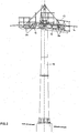
- FIG.2 a support 11 of this cable car system is shown, at the upper end of which are arranged on rockers 12 support rollers 3a, over which a support and hoisting cable 1b is guided. By the movement of the supporting and conveying cable 1b, the support rollers 3a are rotated. At the upper end of the support 11 is further a maintenance platform 13th
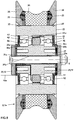
- roller 3 a and 3 consists of a radially inner cylindrical, formed at its radial circumference with paragraphs pipe section 31 on which two axially spaced annular bearings 32 are placed, which sealing blades 32 a are assigned and which by means of spacers 32 b are held in their axial positions.
- a roller body 33 Radially outside of the two annular bearings 32 is a roller body 33.
- a race 34 Radially outside of the roller body 33 is a race 34 to which the interposition of elastic rings 35 laterally each flanged wheel 36 is attached.
- the flanged wheels 36 are held on the roller body 33 by retaining rings 37 in their position.
- the roller body 33 consists of two roller body parts 33a and 33b.
- electrically insulating sleeves 31a are inserted at its two ends and in its central region a middle sleeve 31b, which sleeves 31a and 31b are made of a plastic material.
- the race 34 is made of a hard elastic plastic material.
- the elastic rings 35 serve to press the two flanged wheels 36 against the retaining rings 37.
- In the roller body 33 is further a screw 38, which serves to secure the position of the race 34.
- annular cavity 30 is formed by the fact that the two annular bearings 32 are at an axial distance from each other, whereby an annular space 30 a is formed between them, and that the roller body 33 in his middle region is formed with an annular recess 30b.
- a generator 4 which consists of an annular soft iron core 41 located at this induction coils 42 and this associated permanent magnet 43.
- the induction coils 42 are connected in series.
- the soft iron core 41 is mounted on a support ring 44, which is also placed on the pipe section 31.
- the permanent magnets 43 are mounted on a support ring 43a or are formed as a support ring 43a, said support ring 43a is also inserted into the located within the roller body 33 cavity 30 and is coupled to the roller body 33 to rotate.
- the permanent magnets 43 which are rotatable with the roller body 33 with respect to the pipe section 31, constitute the rotor of the generator 4.
- the induction coils 42 are adjoined by a line 42a which is led out of the roller 3, 3a.
- a pressure compensation element 45 is formed with the roller body portion 33a through which moisture in the cavity 30 can escape therefrom.
- the roller 3 or support roller 3a is by means of a pipe piece 31 passing through bolt 5 on the chassis 21 of a cable car cabin 2 and on a rocker 12, which is located on a support bracket 11, attached.
- the pipe section 31 and with this the stator of the generator 4 are fixed to the frame, whereas the roller body 33 and with this the permanent magnets 43 by means of the annular bearing 32 relative to the pipe section 31 are rotatable.
- the first roller body part 33a is formed with the raceway 34, the elastic rings 35, the flanged wheels 36, the locking rings 37, the pressure compensation element 45 and the locking screw 38.
- the inner surface of the first roller body part 33a is formed with circumferential heels.
- the support ring 43a with the permanent magnets 43 is inserted from the right.
- the left annular bearing 32 is pressed from the left.
- the preassembled pipe section 31 with the support ring 44, the soft iron core 41, the induction coil 42 and the line 42 a is inserted into the annular left bearing 32 from the right.
- the second roller body part 33b with the annular right-hand bearing 32 pressed into it is inserted from the right into the first roller body part 33a and onto the tube piece 31.
- the sleeve 31b, a sealing blade 32a, a spacer ring 32b and a sleeve 31a and from the right a sealing blade 32a, a spacer ring 32b and a sleeve 31a used.
- FIG. 5 illustrated second embodiment of a roller according to the invention 3 or support roller 3a agrees with the in FIG.3 shown roller 3 and support roller 3a largely match, the functionally identical components are provided with the same reference numerals.
- This roller 3 or support roller 3a differs from the roller 3, 3a according to FIG.3 in that the roller body 33 is formed in one piece, wherein it is approximately hollow cylindrical.
- the support ring 31, the soft iron core 41 with the induction coils 42, the support ring 43a formed with the permanent magnets 43, the two annular bearings 32, the sealing fins 32a, the spacers 32b, and the sleeves 31a and 31b can be inserted therein.
- a roller 3 and a support roller 3a are created, which coincides in their outer design with the rollers used in the cableway system or idlers identical, whereby they can be used instead of one of the rollers or support rollers, where they also the function of an electric generator fulfilled without the need for further technical measures.
- Such a roller or idler roller additionally serves to generate power for feeding electrical devices or accumulators.
- the generator 4 is located inside this roller 3 or carrying roller 3a, it is optimally secured against climatic influences, in particular against the penetration of water or moisture.
Landscapes
- Engineering & Computer Science (AREA)
- Mechanical Engineering (AREA)
- General Engineering & Computer Science (AREA)
- Transportation (AREA)
- Power Engineering (AREA)
- Rollers For Roller Conveyors For Transfer (AREA)
- Connection Of Motors, Electrical Generators, Mechanical Devices, And The Like (AREA)
- Rolling Contact Bearings (AREA)
- Rolls And Other Rotary Bodies (AREA)
Description
- Die gegenständliche Erfindung betrifft eine Laufrolle bzw. eine Tragrolle zur Verwendung bei Seilbahnanlagen, mit einem radial innen befindlichen zylindrischen Rohrstück, mit zwei radial außerhalb des Rohrstückes und voneinander in einem axialen Abstand befindlichen ringförmigen Lagern und mit einem radial außerhalb der ringförmigen Lager befindlichen Rollenkörper, welcher mit einem Laufring und mit zwei seitlich desselben befindlichen Bordscheiben ausgebildet ist.
- Es ist bei Beförderungsanlagen mit längs Tragseilen oder längs Führungsschienen bewegbaren Fahrzeugen bekannt, die in den Fahrzeugen befindlichen elektrischen Einrichtungen mittels Akkumulatoren mit elektrischer Energie zu versorgen. Dabei besteht das Erfordernis, die Akkumulatoren in den Stationen der Beförderungsanlagen aufzuladen, was jedoch bei solchen Beförderungsanlagen, bei welchen die Fahrzeuge andauernd bewegt werden, einen großen technischen Aufwand bedingt. Zudem besteht mit ansteigendem Ausmaß von elektrischen Geräten das Erfordernis für erhöhte Kapazitäten dieser Akkumulatoren. Aus diesem Grund wird es angestrebt, die erforderliche elektrische Energie durch die Bewegung der Fahrzeuge zu erzeugen, wobei die elektrischen Geräte und Anlagen unmittelbar mit Strom versorgt werden bzw. die Akkumulatoren aufgeladen werden.
- Aus der
EP-1992539 B1 ist es bekannt, bei einer Seilbahnanlage, bei welcher Seilbahnkabinen längs eines Tragseiles verfahren werden, das Fahrwerk der Seilbahnkabinen mit mindestens einem Reibrad auszustatten, welches am Tragseil abrollt und welches mit einem Generator ausgebildet ist, welcher durch das Reibrad betrieben wird. Hierdurch wird es ermöglicht, durch die Bewegung der Seilbahnkabinen längs eines Tragseiles mittels des am Fahrwerk befindlichen Generators Strom zu erzeugen, durch welchen die in den Seilbahnkabinen befindlichen elektrischen Einrichtungen und Anlagen direkt mit Strom versorgt werden bzw. Akkumulatoren aufgeladen werden. - Diese bekannte Einrichtung bedingt jedoch insofern einen technischen Aufwand, da das Fahrwerk der Seilbahnkabmen zusätzlich mit mindestens einem Reibrad ausgebildet sein muss.
- Aus der
WO 2008/129019 A1 ist weiters eine Beförderungsanlage bekannt, welche mit Laufrollen versehene Fahrzeuge aufweist, wobei eine der Laufrollen mit einem Generator ausgebildet ist. Dabei befindet sich der Generator an der Außenseite dieser Laufrolle, wobei dessen Rotor zugleich mit der Laufrolle verdreht wird.
Diese bekannte Einrichtung ist jedoch deshalb nachteilig, da bei der konstruktiven Gestaltung der gesamten Beförderungsanlage berücksichtigt werden muss, dass die Fahrzeuge mit mindestens einer Laufrolle ausgebildet sind, von welcher in axialer Richtung ein Generator abragt. Zudem besteht das Erfordernis, diesen außen an den Laufrollen befindlichen Generator gegen störende Einflüsse, insbesondere gegen den Eintritt von Feuchtigkeit und Wasser, zu schützen. - Bei Seilbahnanlagen liegt weiters der Sachverhalt vor, dass die Trag- und Förderseile für die Seilbahnkabinen bzw. die Zugseile für entlang von Tragseilen bewegten Seilbahnkabinen im Bereich von Stützen über Tragrollen geführt sind, welche durch die Bewegung der Trag- und Förderseile bzw. der Zugseile verdreht werden und dass auch an Stützen elektrische Einrichtungen, wie Sender, Empfänger, Steuergeräte, Messgeräte u.dgl., vorgesehen sind, für welche eine elektrische Versorgung vorgesehen sein muss. Diese elektrischen Einrichtungen werden bisher über zu den Stützen verlegte elektrische Leitungen mit Strom versorgt. Alternativ dazu sind an den Stützen Solarkollektoren und Akkumulatoren vorgesehen, durch welche eine elektrische Versorgung erfolgt.
- Der gegenständlichen Erfindung liegt die Aufgabe zugrunde, eine Laufrolle für ein Fahrzeug einer Seilbahnanlage bzw. eine Tragrolle für ein Trag- und Förderseil bzw. für ein Zugseil einer Seilbahnanlage, zu schaffen, durch welche bei deren Verdrehung auch die Funktion eines elektrischen Generators erfüllt wird, wobei die den bekannten mit einem Generator ausgebildeten Rollen anhaftenden Nachteile vermieden werden.
- Diese Aufgabe wird bei einer Laufrolle bzw. einer Tragrolle zur Verwendung bei Seilbahnanlagen, mit einem radial innen befindlichen zylindrischen Rohrstück, mit zwei radial außerhalb des Rohstückes und voneinander in einem axialen Abstand befindlichen ringförmigen Lagern und mit einem radial außerhalb der ringförmigen Lager befindlichen Rollenkörper, welcher mit einem Laufring und mit zwei seitlich desselben befindlichen Bordscheiben ausgebildet ist, dadurch gelöst, dass die Rolle mit einem ringförmigen elektrischen Generator ausgebildet ist, welcher sich innerhalb eines vom Rollenkörper und den beiden ringförmigen Lagern umgebenen Hohlraumes befindet.
- Vorzugsweise ist der elektrische Generator durch einen ringförmigen Stator mit mindestens einer Induktionsspule und mit mindestens einem gegenüber dem Stator bewegbaren Permanentmagneten gebildet, wobei der ringförmige Stator, welcher vom Rohrstück getragen ist, sich radial außerhalb des Rohrstückes und in axialer Richtung zwischen den beiden ringförmigen Lagern befindet, und der mindestens eine Permanentmagnet, welcher sich radial außerhalb des Stators befindet, mit dem gegenüber dem Rohrstück verdrehbaren Rollenkörper auf Verdrehung verbunden ist.
Dabei kann sich der mindestens eine Permanentmagnet auf einem Tragring befinden bzw. können Permanentmagneten als Tragring ausgebildet sein, wobei der Tragring am Rollenkörper befestigt ist. Weiters kann sich der ringförmige Stator auf einem am Rohrstück angeordneten ringförmigen Träger befinden. - Nach einer weiters bevorzugten Ausführungsform ist der Rollenkörper zweiteilig ausgebildet und umgeben die beiden Teile des Rollenkörpers den ringförmigen Hohlraum, in welchem sich der ringförmige Generator befindet.
- Der Gegenstand der Erfindung ist nachstehend anhand eines in der Zeichnung dargestellten Ausführungsbeispiels näher erläutert. Es zeigen:
- FIG.1
- einen Abschnitt einer Seilbahnanlage mit einer Seilbahnkabinen, welche mittels eines Fahrwerkes, das durch ein Zugseil bewegt wird, längs eines Tragseiles der Seilbahnanlage verfahrbar ist, in Seitenansicht,
- FIG.2
- eine Stütze der Seilbahnanlage, auf welcher sich eine Rollenbatterie befindet, über welche ein Trag- und Förderseil geführt ist, in Seitenansicht,
- FIG.3
- eine erste Ausführungsform einer erfindungsgemäßen Laufrolle bzw. Tragrolle für eine Seilbahnanlage, in axialem Schnitt,
- FIG.3A
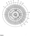
- die Laufrolle bzw. Seilrolle gemäß
FIG.3 in einem Schnitt nach der Linie IIIA-IIIA derFIG.3 und in gegenüberFIG.3 verkleinertem Maßstab, - FIG.4
- die Laufrolle bzw. Tragrolle gemäß
FIG.3 , im Schnitt sowie in auseinander gezogener Darstellung sowie in gegenüberFIG.3 verkleinertem Maßstab, und - FIG.5
- eine zweite Ausführungsform einer erfindungsgemäßen Laufrolle bzw. Tragrolle, in axialem Schnitt.
- In
FIG. 1 ist der Abschnitt einer Seilbahnanlage dargestellt, welche ein Tragseil 1, ein Zugseil 1a und Seilbahnkabinen 2 aufweist, wobei die Seilbahnkabinen 2 mittels des Zugseiles 1a längs des Tragseiles 1 verfahrbar sind. Die Seilbahnkabinen 2 sind mit an einem Fahrwerk 21 gelagerten Laufrollen 3 ausgebildet, wobei das Fahrwerk 21, an welchem die Seilbahnkabine 2 mittels einer Tragstange 22 befestigt ist, längs des Tragseiles 1 verfahrbar ist. Die Tragstange 22 ist am Fahrwerk 21 mittels eines Gelenkes 23 um eine angenähert im rechten Winkel zur Bewegungsrichtung und angenähert horizontal ausgerichtete Achse verschwenkbar. Das Fahrwerk 21 ist mit einer Klemmeinrichtung 24 ausgebildet, mittels welcher die Seilbahnkabine 2 an das Zugseil 1a ankuppelbar ist.
InFIG.2 ist eine Stütze 11 dieser Seilbahnanlage dargestellt, an deren oberem Ende sich auf Schwingen 12 angeordnete Tragrollen 3a befinden, über welche ein Trag- und Förderseil 1b geführt ist. Durch die Bewegung des Trag- und Förderseiles 1b werden die Tragrollen 3a verdreht. Am oberen Ende der Stütze 11 befindet sich weiters eine Wartungsbühne 13. - Die in den
FIG.3 undFIG.3A dargestellte Laufrolle 3 bzw. Tragrolle 3a besteht aus einem radial innen liegenden zylindrischen, an seinem radialen Umfang mit Absätzen ausgebildeten Rohrstück 31, auf welches zwei in axialem Abstand voneinander befindliche ringförmige Lager 32 aufgesetzt sind, welchen Dichtungslamellen 32a zugeordnet sind und welche mittels Distanzringen 32b in ihren axialen Lagen gehalten sind. Radial außerhalb der beiden ringförmigen Lager 32 befindet sich ein Rollenkörper 33. Radial außerhalb des Rollenkörpers 33 befindet sich ein Laufring 34, an welchen unter Zwischenlage von elastischen Ringen 35 seitlich jeweils eine Bordscheibe 36 angesetzt ist. Die Bordscheiben 36 sind am Rollenkörper 33 durch Sicherungsringe 37 in ihrer Lage gehalten. Der Rollenkörper 33 besteht aus zwei Rollenkörperteilen 33a und 33b. - In das Rohrstück 31 sind an seinen beiden Enden elektrisch isolierende Hülsen 31a und in seinem mittleren Bereich eine mittlere Hülse 31b eingesetzt, welche Hülsen 31a und 31b aus einem Kunststoffmaterial bestehen. Der Laufring 34 ist aus einem hartelastischen Kunststoffmaterial hergestellt. Die elastischen Ringe 35 dienen dazu, die beiden Bordscheiben 36 gegen die Sicherungsringe 37 zu drücken. Im Rollenkörper 33 befindet sich weiters eine Schraube 38, welche zur Lagesicherung des Laufringes 34 dient.
- Zwischen dem Rohrstück 31 und dem Rollenkörper 33 befindet sich ein ringförmiger Hohlraum 30, welcher dadurch gebildet ist, dass sich die beiden ringförmigen Lager 32 voneinander in einem axialen Abstand befinden, wodurch zwischen diesen ein Ringraum 30a gebildet ist, und dass der Rollenkörper 33 in seinem mittleren Bereich mit einer ringförmigen Ausnehmung 30b ausgebildet ist. Im ringförmigen Hohlraum 30 befindet sich ein Generator 4, welcher aus einem ringförmigen Weicheisenkern 41 an diesem befindlichen Induktionsspulen 42 und diesem zugeordneten Permanentmagneten 43 besteht. Die Induktionsspulen 42 sind in Serie geschaltet. Der Weicheisenkern 41 ist auf einem Tragring 44 befestigt, welcher gleichfalls auf das Rohrstück 31 aufgesetzt ist. Die Permanentmagneten 43 sind auf einem Tragring 43a befestigt bzw. sind als Tragring 43a ausgebildet, wobei dieser Tragring 43a gleichfalls in den innerhalb des Rollenkörpers 33 befindlichen Hohlraum 30 eingesetzt ist und mit dem Rollenkörper 33 auf Verdrehung gekuppelt ist.
- Der Weicheisenkern 41 mit den Induktionsspulen 42 stellt dabei den Stator des Generators 4 dar. Demgegenüber stellen die Permanentmagneten 43, welche mit dem Rollenkörper 33 gegenüber dem Rohrstück 31 verdrehbar sind, den Rotor des Generators 4 dar. An die Induktionsspulen 42 schließt eine Leitung 42a an, welche aus der Rolle 3, 3a hinausgeführt ist. Der Rollenkörperteil 33a ist mit einem Druckausgleichselement 45 ausgebildet, durch welches hindurch im Hohlraum 30 befindliche Feuchtigkeit aus diesem austreten kann.
- Die Laufrolle 3 bzw. Tragrolle 3a ist mittels eines das Rohrstück 31 durchsetzenden Bolzens 5 am Fahrwerk 21 einer Seilbahnkabine 2 bzw. auf einer Schwinge 12, welche sich auf einer Tragstütze 11 befindet, befestigt. Hierdurch sind das Rohrstück 31 und mit diesem der Stator des Generators 4 gestellfest angeordnet, wogegen der Rollenkörper 33 und mit diesem die Permanentmagneten 43 mittels der ringförmigen Lager 32 gegenüber dem Rohrstück 31 verdrehbar sind.
- Durch eine Verdrehung des Rollenkörpers 33 gegenüber dem Rohrstück 31 erfolgt eine Bewegung der Permanentmagneten 43 gegenüber den Induktionsspulen 42, wodurch in diesen ein Wechselstrom erzeugt wird, welcher über die Leitung 42a zu den in der Seilbahnkabine 2 bzw. an den Stützen 11 vorgesehenen elektrischen Verbrauchern bzw. zu Akkumulatoren geführt wird. Die Verdrehung einer Laufrolle 3 erfolgt durch deren Abrollen längs eines Tragseiles 1 und die Verdrehung einer Tragrolle 3a erfolgt durch ein über diese geführtes Zugseil 1a bzw. durch ein über diese geführtes Trag-und Förderseil 1b.
- Nachstehend ist anhand der
FIG.4 die Zusammenstellung einer Tragrolle 3 bzw. einer Laufrolle 3a erläutert. Der erste Rollenkörperteil 33a ist mit dem Laufring 34, den elastischen Ringen 35, den Bordscheiben 36, den Sicherungsringen 37, dem Druckausgleichselement 45 und mit der Sicherungsschraube 38 ausgebildet. Die Innenfläche des ersten Rollenkörperteiles 33a ist mit ringsum verlaufenden Absätzen ausgebildet. In den Rollenkörperteil 33a wird von rechts her der Tragring 43a mit den Permanentmagneten 43 eingesetzt. In weiterer Folge wird von links her das linke ringförmige Lager 32 eingepresst. Anschließend wird von rechts her das vormontierte Rohrstück 31 mit dem Tragring 44, dem Weicheisenkern 41, den Induktionsspulen 42 und der Leitung 42a in das ringförmige linke Lager 32 eingesetzt. Hierauf werden von rechts her in den ersten Rollenkörperteil 33a und auf das Rohrstück 31 der zweite Rollenkörperteil 33b mit dem in diesen eingepressten ringförmigen rechten Lager 32 eingesetzt. Schließlich werden von links her die Hülse 31b, eine Dichtungslamelle 32a, ein Distanzring 32b und eine Hülse 31a sowie von rechts her eine Dichtungslamelle 32a, ein Distanzring 32b und eine Hülse 31a eingesetzt. - Die in
FIG. 5 dargestellte zweite Ausführungsform einer erfindungsgemäßen Laufrolle 3 bzw. Tragrolle 3a stimmt mit der inFIG.3 dargestellten Laufrolle 3 bzw. Tragrolle 3a weitgehend überein, wobei die funktionell gleichen Bauteile mit gleichen Bezugszahlen versehen sind. Diese Laufrolle 3 bzw. Tragrolle 3a unterscheidet sich von der Rolle 3, 3a gemäßFIG.3 dadurch, dass der Rollenkörper 33 einstückig ausgebildet ist, wobei er angenähert hohlzylindrisch ist. Hierdurch können in diesen der Tragring 31, der Weicheisenkern 41 mit den Induktionsspulen 42, der mit den Permanentmagneten 43 ausgebildete Tragring 43a, die beiden ringförmigen Lager 32, die Dichtungslamellen 32a, die Distanzringe 32b und die Hülsen 31a sowie 31b eingesetzt werden. - Hiermit sind eine Laufrolle 3 bzw. eine Tragrolle 3a geschaffen, welche in ihrer äußeren Gestaltung mit den in der Seilbahnanlage verwendeten Laufrollen bzw. Tragrollen identisch übereinstimmt, wodurch sie anstelle einer der Laufrollen bzw. Tragrollen einsetzbar ist, wobei sie zudem die Funktion eines elektrischen Generators erfüllt, ohne dass es hierfür weiterer technischer Maßnahmen bedarf. Eine derartige Laufrolle bzw. Tragrolle dient zusätzlich zur Erzeugung von Strom zur Speisung von elektrischen Geräten oder von Akkumulatoren.
- Dadurch, dass sich der Generator 4 im Inneren dieser Laufrolle 3 bzw. Tragrolle 3a befindet, ist er gegenüber klimatischen Einflüssen, insbesondere gegenüber dem Eindringen von Wasser bzw. Feuchtigkeit, in optimaler Weise gesichert.
Claims (5)
- Laufrolle (3) bzw. Tragrolle (3a) zur Verwendung bei Seilbahnanlagen, mit einem radial innen befindlichen zylindrischen Rohrstück (31), mit zwei radial außerhalb des Rohrstückes und voneinander in einem axialen Abstand befindlichen ringförmigen Lagern (32) und mit einem radial außerhalb der ringförmigen Lager (32) befindlichen Rollenkörper (33), welcher mit einem Laufring (34) und mit zwei seitlich desselben befindlichen Bordscheiben (36) ausgebildet ist, dadurch gekennzeichnet, dass die Rolle (3, 3a) mit einem ringförmigen elektrischen Generator (4) ausgebildet ist, welcher sich innerhalb eines vom Rollenkörper (33) und den beiden ringförmigen Lagern (32) umgebenen Hohlraumes (30) befindet.
- Laufrolle bzw. Tragrolle nach Patentanspruch 1, dadurch gekennzeichnet, dass der elektrische Generator (4) durch einen ringförmigen Stator (41, 42) mit mindestens einer Induktionsspule (42) und durch mindestens einen gegenüber dem Stator (41, 42) bewegbaren Permanentmagneten (43) gebildet ist, wobei der ringförmige Stator (41, 42), welcher vom Rohrstück (31) getragen ist, sich radial außerhalb des Rohrstückes (31) und in axialer Richtung zwischen den beiden ringförmigen Lagern (32) befindet, und der mindestens eine Permanentmagnet (43), welcher sich radial außerhalb des Stators (41, 42) befindet, mit dem gegenüber dem Rohrstück (31) verdrehbaren Rollenkörper (33) auf Verdrehung verbunden ist.
- Laufrolle bzw. Tragrolle nach Patentanspruch 2, dadurch gekennzeichnet, dass der mindestens eine Permanentmagnet (43) als Tragring (43a) ausgebildet ist bzw. sich auf einem Tragring (43a) befindet, wobei der Tragring (43a) am Rollenkörper (33) befestigt ist.
- Laufrolle bzw. Tragrolle nach einem der Patentansprüche 2 oder 3, dadurch gekennzeichnet, dass sich der ringförmige Stator (41, 42) auf einem am Rohrstück (31) angeordneten ringförmigen Träger (44) befindet.
- Laufrolle bzw. Tragrolle nach einem der Patentansprüche 2 bis 4, dadurch gekennzeichnet, dass der Rollenkörper (33) zweiteilig ausgebildet ist und dass die beiden Rollenkörperteile (33a, 33b) einen ringförmigen Hohlraum (30) umgeben, in welchem sich der ringförmige Generator (4) befindet.
Priority Applications (1)
| Application Number | Priority Date | Filing Date | Title |
|---|---|---|---|
| SI201230584A SI2623389T1 (sl) | 2012-02-06 | 2012-11-22 | Tekalno kolo oz. nosilno kolo za žičniške sisteme |
Applications Claiming Priority (1)
| Application Number | Priority Date | Filing Date | Title |
|---|---|---|---|
| ATA155/2012A AT512298B1 (de) | 2012-02-06 | 2012-02-06 | Rolle, insbesondere laufrolle bzw. tragrolle für seilbahnanlagen |
Publications (2)
| Publication Number | Publication Date |
|---|---|
| EP2623389A1 EP2623389A1 (de) | 2013-08-07 |
| EP2623389B1 true EP2623389B1 (de) | 2016-03-30 |
Family
ID=47355989
Family Applications (1)
| Application Number | Title | Priority Date | Filing Date |
|---|---|---|---|
| EP12450048.9A Active EP2623389B1 (de) | 2012-02-06 | 2012-11-22 | Laufrolle bzw. Tragrolle für Seilbahnanlagen |
Country Status (18)
| Country | Link |
|---|---|
| US (1) | US8853871B2 (de) |
| EP (1) | EP2623389B1 (de) |
| KR (1) | KR101663342B1 (de) |
| CN (1) | CN103241245B (de) |
| AR (1) | AR089912A1 (de) |
| AT (1) | AT512298B1 (de) |
| AU (1) | AU2013200396B2 (de) |
| BR (1) | BR102013002526B1 (de) |
| CA (1) | CA2802392C (de) |
| CL (1) | CL2013000370A1 (de) |
| CO (1) | CO7020179A1 (de) |
| ES (1) | ES2578452T3 (de) |
| MA (1) | MA35004B1 (de) |
| MX (1) | MX2013001497A (de) |
| PE (1) | PE20131058A1 (de) |
| PL (1) | PL2623389T3 (de) |
| RU (1) | RU2592190C2 (de) |
| SI (1) | SI2623389T1 (de) |
Families Citing this family (11)
| Publication number | Priority date | Publication date | Assignee | Title |
|---|---|---|---|---|
| CN103939579B (zh) * | 2014-03-21 | 2016-10-26 | 成都科创佳思科技有限公司 | 建筑用滑轮滚装置 |
| AT516963B1 (de) | 2015-03-19 | 2016-10-15 | Innova Patent Gmbh | Anlage zur Versorgung mindestens eines elektrischen Verbrauchers bzw. eines Energiespeichers mit Gleichstrom |
| ITUA20163035A1 (it) * | 2016-04-29 | 2017-10-29 | Leitner Spa | Dispositivo di una rulliera o di un carrello per un impianto di trasporto a fune |
| WO2018220016A1 (de) * | 2017-06-02 | 2018-12-06 | Innova Patent Gmbh | Seilgezogene beförderungseinrichtung und verfahren zum betreiben einer solchen |
| CN109296731A (zh) * | 2018-09-26 | 2019-02-01 | 苏州骏捷升降机械科技有限公司 | 一种链条轮 |
| CN111891142B (zh) * | 2020-09-03 | 2024-06-25 | 山西中科智能控制技术研究院有限公司 | 一种磁牵引行走装置 |
| DE102021110649B3 (de) * | 2021-04-26 | 2022-06-23 | Pentanova Cs Gmbh | Wartungsshuttle für eine Elektrohängebahn |
| CN113483079A (zh) * | 2021-08-12 | 2021-10-08 | 机汇网(深圳)科技有限公司 | 一种可发电的新型滑轮装置 |
| CN113562001B (zh) * | 2021-08-30 | 2025-01-03 | 陕西骏景索道运营管理有限公司 | 一种架空索道支架智能发电轮及其控制方法 |
| CN114476549A (zh) * | 2022-02-24 | 2022-05-13 | 定边县林草工作站 | 一种带有机械滑索的苗木运输装置 |
| CN114776541A (zh) * | 2022-03-29 | 2022-07-22 | 温州大学 | 一种景区清洁能源收集系统 |
Citations (17)
| Publication number | Priority date | Publication date | Assignee | Title |
|---|---|---|---|---|
| AT313364B (de) | 1971-03-24 | 1974-02-11 | Loruenser Leichtmetallwerk Kg | Seilrolle für Seilwegeanlagen |
| CH564445A5 (en) | 1973-07-20 | 1975-07-31 | Vevey Atel Const Mec | Electrical generator used on railway carriages - is assembled in annular space between wheel and axle uses permanent magnet |
| AT342114B (de) | 1976-03-22 | 1978-03-10 | Lorunser Leichtmetallwerk Kg | Seilrolle fur seilwegeanlagen |
| US4559462A (en) | 1984-05-30 | 1985-12-17 | Hernandez Badillo Wilfredo | Dynamo-electric cycle axle |
| DE9201088U1 (de) * | 1992-01-30 | 1993-03-04 | P & H Techno AG, Basel | Elektromotor zum Antrieb eines Rades |
| US5236055A (en) * | 1991-03-13 | 1993-08-17 | Canadian Aging & Rehabilitation Product Development Corporation | Wheel with coaxial drive system mounted in the wheelhub field of the invention |
| WO1994001917A1 (fr) * | 1992-07-14 | 1994-01-20 | Hydro-Quebec | Moteur-roue electrique |
| WO1996022895A1 (de) * | 1995-01-23 | 1996-08-01 | Egon Schmid | Antriebseinrichtung für ein elektrisch betriebenes fahrzeug |
| EP1264761A2 (de) | 2001-06-07 | 2002-12-11 | Shimano Inc. | Fahrradnabe mit Nabenlichtmaschine |
| AT410307B (de) | 2001-07-19 | 2003-03-25 | Innova Patent Gmbh | Rolle für ein laufwerk bzw. für eine rollenbatterie |
| EP0773157B1 (de) | 1995-11-10 | 2004-02-04 | SANYO ELECTRIC Co., Ltd. | Radnabendynamo für Fahrrad |
| US6974144B2 (en) | 2003-06-27 | 2005-12-13 | Shimano, Inc. | Bicycle front end arrangement forming electric power supply system |
| DE102006054979A1 (de) | 2006-04-15 | 2007-10-25 | Sram Deutschland Gmbh | Radnabendynamo |
| DE102008004085A1 (de) * | 2008-01-12 | 2009-07-16 | Daimler Ag | Lageranordnung |
| EP1992539B1 (de) | 2007-05-07 | 2011-02-23 | Innova Patent GmbH | Einrichtung zum Befördern von Personen und/oder Gegenständen |
| US20110156543A1 (en) | 2009-12-25 | 2011-06-30 | Shimano Inc. | Bicycle generator hub |
| EP2314491B1 (de) | 2009-10-23 | 2012-07-04 | Gimar Montaz Mautino | Vorrichtung zur Überwachung der Drehbewegung eines Drehorgans zum Abstützen und Lenken in einer Skilift-Anlage |
Family Cites Families (7)
| Publication number | Priority date | Publication date | Assignee | Title |
|---|---|---|---|---|
| WO1993011015A1 (fr) * | 1991-11-29 | 1993-06-10 | Seiko Epson Corporation | Deplacement dans un appareil de transfert et controleur d'entrainement de l'element de transfert |
| CN2129487Y (zh) * | 1992-07-04 | 1993-04-07 | 刘燕 | 自行车发电机 |
| AT409254B (de) * | 2000-07-18 | 2002-07-25 | Innova Patent Gmbh | Laufrolle für das fahrwerk des fahrbetriebsmittels einer seilbahnanlage |
| CN2652462Y (zh) * | 2003-09-15 | 2004-11-03 | 付明华 | 具有发电装置及横向发光元件的轮体 |
| US8093731B2 (en) | 2006-11-07 | 2012-01-10 | Potenco, Inc. | Gearless human power generation |
| ITMI20070835A1 (it) | 2007-04-20 | 2008-10-21 | Rolic Invest Sarl | Impianto di trasporto a fune e metodo di azionamento dello stesso |
| ITMI20071128A1 (it) * | 2007-06-01 | 2008-12-02 | Rolic Invest Sarl | Rullo di rotolamento per una fune di un impianto di trasporto |
-
2012
- 2012-02-06 AT ATA155/2012A patent/AT512298B1/de not_active IP Right Cessation
- 2012-11-22 ES ES12450048.9T patent/ES2578452T3/es active Active
- 2012-11-22 EP EP12450048.9A patent/EP2623389B1/de active Active
- 2012-11-22 SI SI201230584A patent/SI2623389T1/sl unknown
- 2012-11-22 PL PL12450048.9T patent/PL2623389T3/pl unknown
- 2012-12-21 KR KR1020120150847A patent/KR101663342B1/ko not_active Expired - Fee Related
-
2013
- 2013-01-05 CN CN201310002295.1A patent/CN103241245B/zh active Active
- 2013-01-14 RU RU2013101603/11A patent/RU2592190C2/ru active
- 2013-01-16 CA CA2802392A patent/CA2802392C/en active Active
- 2013-01-17 US US13/743,929 patent/US8853871B2/en active Active
- 2013-01-25 AU AU2013200396A patent/AU2013200396B2/en not_active Ceased
- 2013-02-01 BR BR102013002526-7A patent/BR102013002526B1/pt not_active IP Right Cessation
- 2013-02-05 MA MA35640A patent/MA35004B1/fr unknown
- 2013-02-06 CO CO13024409A patent/CO7020179A1/es active IP Right Grant
- 2013-02-06 AR ARP130100359A patent/AR089912A1/es active IP Right Grant
- 2013-02-06 CL CL2013000370A patent/CL2013000370A1/es unknown
- 2013-02-06 MX MX2013001497A patent/MX2013001497A/es active IP Right Grant
- 2013-02-06 PE PE2013000215A patent/PE20131058A1/es active IP Right Grant
Patent Citations (17)
| Publication number | Priority date | Publication date | Assignee | Title |
|---|---|---|---|---|
| AT313364B (de) | 1971-03-24 | 1974-02-11 | Loruenser Leichtmetallwerk Kg | Seilrolle für Seilwegeanlagen |
| CH564445A5 (en) | 1973-07-20 | 1975-07-31 | Vevey Atel Const Mec | Electrical generator used on railway carriages - is assembled in annular space between wheel and axle uses permanent magnet |
| AT342114B (de) | 1976-03-22 | 1978-03-10 | Lorunser Leichtmetallwerk Kg | Seilrolle fur seilwegeanlagen |
| US4559462A (en) | 1984-05-30 | 1985-12-17 | Hernandez Badillo Wilfredo | Dynamo-electric cycle axle |
| US5236055A (en) * | 1991-03-13 | 1993-08-17 | Canadian Aging & Rehabilitation Product Development Corporation | Wheel with coaxial drive system mounted in the wheelhub field of the invention |
| DE9201088U1 (de) * | 1992-01-30 | 1993-03-04 | P & H Techno AG, Basel | Elektromotor zum Antrieb eines Rades |
| WO1994001917A1 (fr) * | 1992-07-14 | 1994-01-20 | Hydro-Quebec | Moteur-roue electrique |
| WO1996022895A1 (de) * | 1995-01-23 | 1996-08-01 | Egon Schmid | Antriebseinrichtung für ein elektrisch betriebenes fahrzeug |
| EP0773157B1 (de) | 1995-11-10 | 2004-02-04 | SANYO ELECTRIC Co., Ltd. | Radnabendynamo für Fahrrad |
| EP1264761A2 (de) | 2001-06-07 | 2002-12-11 | Shimano Inc. | Fahrradnabe mit Nabenlichtmaschine |
| AT410307B (de) | 2001-07-19 | 2003-03-25 | Innova Patent Gmbh | Rolle für ein laufwerk bzw. für eine rollenbatterie |
| US6974144B2 (en) | 2003-06-27 | 2005-12-13 | Shimano, Inc. | Bicycle front end arrangement forming electric power supply system |
| DE102006054979A1 (de) | 2006-04-15 | 2007-10-25 | Sram Deutschland Gmbh | Radnabendynamo |
| EP1992539B1 (de) | 2007-05-07 | 2011-02-23 | Innova Patent GmbH | Einrichtung zum Befördern von Personen und/oder Gegenständen |
| DE102008004085A1 (de) * | 2008-01-12 | 2009-07-16 | Daimler Ag | Lageranordnung |
| EP2314491B1 (de) | 2009-10-23 | 2012-07-04 | Gimar Montaz Mautino | Vorrichtung zur Überwachung der Drehbewegung eines Drehorgans zum Abstützen und Lenken in einer Skilift-Anlage |
| US20110156543A1 (en) | 2009-12-25 | 2011-06-30 | Shimano Inc. | Bicycle generator hub |
Also Published As
| Publication number | Publication date |
|---|---|
| AU2013200396B2 (en) | 2014-12-04 |
| CA2802392A1 (en) | 2013-08-06 |
| MX2013001497A (es) | 2013-08-27 |
| BR102013002526A8 (pt) | 2018-05-02 |
| CA2802392C (en) | 2017-02-07 |
| US8853871B2 (en) | 2014-10-07 |
| RU2592190C2 (ru) | 2016-07-20 |
| PE20131058A1 (es) | 2013-10-03 |
| PL2623389T3 (pl) | 2016-10-31 |
| ES2578452T3 (es) | 2016-07-27 |
| SI2623389T1 (sl) | 2016-07-29 |
| AT512298A4 (de) | 2013-07-15 |
| EP2623389A1 (de) | 2013-08-07 |
| BR102013002526B1 (pt) | 2022-03-29 |
| AT512298B1 (de) | 2013-07-15 |
| RU2013101603A (ru) | 2014-07-20 |
| CL2013000370A1 (es) | 2014-09-26 |
| BR102013002526A2 (pt) | 2015-06-02 |
| CN103241245B (zh) | 2017-03-01 |
| CO7020179A1 (es) | 2014-08-11 |
| KR101663342B1 (ko) | 2016-10-06 |
| MA35004B1 (fr) | 2014-04-03 |
| AR089912A1 (es) | 2014-10-01 |
| AU2013200396A1 (en) | 2013-08-22 |
| US20130200631A1 (en) | 2013-08-08 |
| KR20130090741A (ko) | 2013-08-14 |
| CN103241245A (zh) | 2013-08-14 |
Similar Documents
| Publication | Publication Date | Title |
|---|---|---|
| EP2623389B1 (de) | Laufrolle bzw. Tragrolle für Seilbahnanlagen | |
| DE69524014T2 (de) | Wälzlager mit eingebautem elektrischen Generator | |
| EP1804363B1 (de) | Achsgenerator für Eisenbahnwagen und schienengebundene, nicht selbstangetriebene Fahrzeuge | |
| EP3765396B1 (de) | Kran | |
| CH703662A1 (de) | Inspektionsfahrzeug für die inspektion eines luftspalts zwischen dem rotor und dem stator eines generators. | |
| DE102008038146A1 (de) | Vorrichtung zum Behandeln von Behältern | |
| DE102004012946A1 (de) | Windenergieanlage | |
| EP3807072A1 (de) | Vorrichtung und verfahren zum ablängen eines extrudierten rohres | |
| DE102010047139A1 (de) | Planetentrieb | |
| AT516963A4 (de) | Anlage zur Versorgung mindestens eines elektrischen Verbrauchers bzw. eines Energiespeichers mit Gleichstrom | |
| DE102014109068A1 (de) | Vorrichtung zur automatischen Positionierung eines Kontaktierelementes für Fahrzeuge mit elektrischem Antrieb | |
| DE102004022299A1 (de) | Windenergieanlage | |
| DE102018114472B4 (de) | Verfahren und Vorrichtung zum Ablängen eines extrudierten Rohres | |
| DE19639091C2 (de) | Vorrichtung zur Versorgung der Überwachungs-, Regel- und Steueraggregate eines Gurtförderers mit elektrischer Energie | |
| DE102007048244A1 (de) | Kraftfahrzeugrad, magnetisch gelagert | |
| EP3294601B1 (de) | Mechanisch-elektrischer antrieb | |
| DE102009035420B4 (de) | Rotationsvorrichtung zur Verwendung in einem Fluid | |
| DE102021123843B4 (de) | Trommelanordnung | |
| DE102014216244A1 (de) | Verfahren zum Austausch eines Wälzlagers und Verfahren zum axialen Verschieben eines WKA-Getriebes | |
| EP3323691B1 (de) | Anordnung zur versorgung eines schienenfahrzeugs und verfahren zum herstellen der anordnung | |
| DE102019126209A1 (de) | Rolle oder Trommel mit Drucksensoren | |
| DE10060582A1 (de) | Förderanlage zum Transport von Gegenständen sowie Sensoreinrichtung zur Verwendung in einer solchen Förderanlage | |
| DE102008017667A1 (de) | Lager mit einem geerdeten, drehbaren Lagerring | |
| DE102010046611A1 (de) | Drahtführungseinheit | |
| DE102014211576A1 (de) | Kraftfahrzeug mit einem Energiespeicher |
Legal Events
| Date | Code | Title | Description |
|---|---|---|---|
| PUAI | Public reference made under article 153(3) epc to a published international application that has entered the european phase |
Free format text: ORIGINAL CODE: 0009012 |
|
| AK | Designated contracting states |
Kind code of ref document: A1 Designated state(s): AL AT BE BG CH CY CZ DE DK EE ES FI FR GB GR HR HU IE IS IT LI LT LU LV MC MK MT NL NO PL PT RO RS SE SI SK SM TR |
|
| AX | Request for extension of the european patent |
Extension state: BA ME |
|
| 17P | Request for examination filed |
Effective date: 20130911 |
|
| RBV | Designated contracting states (corrected) |
Designated state(s): AL AT BE BG CH CY CZ DE DK EE ES FI FR GB GR HR HU IE IS IT LI LT LU LV MC MK MT NL NO PL PT RO RS SE SI SK SM TR |
|
| 17Q | First examination report despatched |
Effective date: 20140401 |
|
| RIN1 | Information on inventor provided before grant (corrected) |
Inventor name: LUGER, PETER Inventor name: MORITZHUBER, JOHANNES |
|
| GRAP | Despatch of communication of intention to grant a patent |
Free format text: ORIGINAL CODE: EPIDOSNIGR1 |
|
| INTG | Intention to grant announced |
Effective date: 20151202 |
|
| GRAS | Grant fee paid |
Free format text: ORIGINAL CODE: EPIDOSNIGR3 |
|
| GRAA | (expected) grant |
Free format text: ORIGINAL CODE: 0009210 |
|
| AK | Designated contracting states |
Kind code of ref document: B1 Designated state(s): AL AT BE BG CH CY CZ DE DK EE ES FI FR GB GR HR HU IE IS IT LI LT LU LV MC MK MT NL NO PL PT RO RS SE SI SK SM TR |
|
| REG | Reference to a national code |
Ref country code: GB Ref legal event code: FG4D Free format text: NOT ENGLISH |
|
| REG | Reference to a national code |
Ref country code: CH Ref legal event code: EP |
|
| REG | Reference to a national code |
Ref country code: AT Ref legal event code: REF Ref document number: 785032 Country of ref document: AT Kind code of ref document: T Effective date: 20160415 |
|
| REG | Reference to a national code |
Ref country code: IE Ref legal event code: FG4D Free format text: LANGUAGE OF EP DOCUMENT: GERMAN |
|
| REG | Reference to a national code |
Ref country code: DE Ref legal event code: R096 Ref document number: 502012006492 Country of ref document: DE |
|
| REG | Reference to a national code |
Ref country code: CH Ref legal event code: NV Representative=s name: OFFICE ERNEST T. FREYLINGER S.A., CH |
|
| REG | Reference to a national code |
Ref country code: SE Ref legal event code: TRGR |
|
| REG | Reference to a national code |
Ref country code: LT Ref legal event code: MG4D |
|
| REG | Reference to a national code |
Ref country code: ES Ref legal event code: FG2A Ref document number: 2578452 Country of ref document: ES Kind code of ref document: T3 Effective date: 20160727 Ref country code: NL Ref legal event code: FP |
|
| PG25 | Lapsed in a contracting state [announced via postgrant information from national office to epo] |
Ref country code: HR Free format text: LAPSE BECAUSE OF FAILURE TO SUBMIT A TRANSLATION OF THE DESCRIPTION OR TO PAY THE FEE WITHIN THE PRESCRIBED TIME-LIMIT Effective date: 20160330 Ref country code: GR Free format text: LAPSE BECAUSE OF FAILURE TO SUBMIT A TRANSLATION OF THE DESCRIPTION OR TO PAY THE FEE WITHIN THE PRESCRIBED TIME-LIMIT Effective date: 20160701 |
|
| REG | Reference to a national code |
Ref country code: NO Ref legal event code: T2 Effective date: 20160330 |
|
| PG25 | Lapsed in a contracting state [announced via postgrant information from national office to epo] |
Ref country code: RS Free format text: LAPSE BECAUSE OF FAILURE TO SUBMIT A TRANSLATION OF THE DESCRIPTION OR TO PAY THE FEE WITHIN THE PRESCRIBED TIME-LIMIT Effective date: 20160330 Ref country code: LV Free format text: LAPSE BECAUSE OF FAILURE TO SUBMIT A TRANSLATION OF THE DESCRIPTION OR TO PAY THE FEE WITHIN THE PRESCRIBED TIME-LIMIT Effective date: 20160330 Ref country code: LT Free format text: LAPSE BECAUSE OF FAILURE TO SUBMIT A TRANSLATION OF THE DESCRIPTION OR TO PAY THE FEE WITHIN THE PRESCRIBED TIME-LIMIT Effective date: 20160330 |
|
| REG | Reference to a national code |
Ref country code: DE Ref legal event code: R026 Ref document number: 502012006492 Country of ref document: DE |
|
| PLBI | Opposition filed |
Free format text: ORIGINAL CODE: 0009260 |
|
| 26 | Opposition filed |
Opponent name: LEITNER AG Effective date: 20160907 |
|
| PG25 | Lapsed in a contracting state [announced via postgrant information from national office to epo] |
Ref country code: EE Free format text: LAPSE BECAUSE OF FAILURE TO SUBMIT A TRANSLATION OF THE DESCRIPTION OR TO PAY THE FEE WITHIN THE PRESCRIBED TIME-LIMIT Effective date: 20160330 Ref country code: IS Free format text: LAPSE BECAUSE OF FAILURE TO SUBMIT A TRANSLATION OF THE DESCRIPTION OR TO PAY THE FEE WITHIN THE PRESCRIBED TIME-LIMIT Effective date: 20160730 |
|
| REG | Reference to a national code |
Ref country code: SK Ref legal event code: T3 Ref document number: E 21283 Country of ref document: SK |
|
| REG | Reference to a national code |
Ref country code: FR Ref legal event code: PLFP Year of fee payment: 5 |
|
| PG25 | Lapsed in a contracting state [announced via postgrant information from national office to epo] |
Ref country code: RO Free format text: LAPSE BECAUSE OF FAILURE TO SUBMIT A TRANSLATION OF THE DESCRIPTION OR TO PAY THE FEE WITHIN THE PRESCRIBED TIME-LIMIT Effective date: 20160330 Ref country code: PT Free format text: LAPSE BECAUSE OF FAILURE TO SUBMIT A TRANSLATION OF THE DESCRIPTION OR TO PAY THE FEE WITHIN THE PRESCRIBED TIME-LIMIT Effective date: 20160801 Ref country code: SM Free format text: LAPSE BECAUSE OF FAILURE TO SUBMIT A TRANSLATION OF THE DESCRIPTION OR TO PAY THE FEE WITHIN THE PRESCRIBED TIME-LIMIT Effective date: 20160330 |
|
| PG25 | Lapsed in a contracting state [announced via postgrant information from national office to epo] |
Ref country code: DK Free format text: LAPSE BECAUSE OF FAILURE TO SUBMIT A TRANSLATION OF THE DESCRIPTION OR TO PAY THE FEE WITHIN THE PRESCRIBED TIME-LIMIT Effective date: 20160330 |
|
| PLAX | Notice of opposition and request to file observation + time limit sent |
Free format text: ORIGINAL CODE: EPIDOSNOBS2 |
|
| PG25 | Lapsed in a contracting state [announced via postgrant information from national office to epo] |
Ref country code: BE Free format text: LAPSE BECAUSE OF NON-PAYMENT OF DUE FEES Effective date: 20161130 |
|
| PLBB | Reply of patent proprietor to notice(s) of opposition received |
Free format text: ORIGINAL CODE: EPIDOSNOBS3 |
|
| RAP2 | Party data changed (patent owner data changed or rights of a patent transferred) |
Owner name: INNOVA PATENT GMBH |
|
| REG | Reference to a national code |
Ref country code: IE Ref legal event code: MM4A |
|
| PG25 | Lapsed in a contracting state [announced via postgrant information from national office to epo] |
Ref country code: LU Free format text: LAPSE BECAUSE OF NON-PAYMENT OF DUE FEES Effective date: 20161130 |
|
| REG | Reference to a national code |
Ref country code: FR Ref legal event code: PLFP Year of fee payment: 6 |
|
| PG25 | Lapsed in a contracting state [announced via postgrant information from national office to epo] |
Ref country code: IE Free format text: LAPSE BECAUSE OF NON-PAYMENT OF DUE FEES Effective date: 20161122 |
|
| REG | Reference to a national code |
Ref country code: BE Ref legal event code: MM Effective date: 20161130 |
|
| PG25 | Lapsed in a contracting state [announced via postgrant information from national office to epo] |
Ref country code: HU Free format text: LAPSE BECAUSE OF FAILURE TO SUBMIT A TRANSLATION OF THE DESCRIPTION OR TO PAY THE FEE WITHIN THE PRESCRIBED TIME-LIMIT; INVALID AB INITIO Effective date: 20121122 Ref country code: CY Free format text: LAPSE BECAUSE OF FAILURE TO SUBMIT A TRANSLATION OF THE DESCRIPTION OR TO PAY THE FEE WITHIN THE PRESCRIBED TIME-LIMIT Effective date: 20160330 |
|
| PG25 | Lapsed in a contracting state [announced via postgrant information from national office to epo] |
Ref country code: MC Free format text: LAPSE BECAUSE OF FAILURE TO SUBMIT A TRANSLATION OF THE DESCRIPTION OR TO PAY THE FEE WITHIN THE PRESCRIBED TIME-LIMIT Effective date: 20160330 Ref country code: MK Free format text: LAPSE BECAUSE OF FAILURE TO SUBMIT A TRANSLATION OF THE DESCRIPTION OR TO PAY THE FEE WITHIN THE PRESCRIBED TIME-LIMIT Effective date: 20160330 |
|
| PG25 | Lapsed in a contracting state [announced via postgrant information from national office to epo] |
Ref country code: BG Free format text: LAPSE BECAUSE OF FAILURE TO SUBMIT A TRANSLATION OF THE DESCRIPTION OR TO PAY THE FEE WITHIN THE PRESCRIBED TIME-LIMIT Effective date: 20160330 |
|
| PG25 | Lapsed in a contracting state [announced via postgrant information from national office to epo] |
Ref country code: MT Free format text: LAPSE BECAUSE OF FAILURE TO SUBMIT A TRANSLATION OF THE DESCRIPTION OR TO PAY THE FEE WITHIN THE PRESCRIBED TIME-LIMIT Effective date: 20160330 |
|
| PG25 | Lapsed in a contracting state [announced via postgrant information from national office to epo] |
Ref country code: AL Free format text: LAPSE BECAUSE OF FAILURE TO SUBMIT A TRANSLATION OF THE DESCRIPTION OR TO PAY THE FEE WITHIN THE PRESCRIBED TIME-LIMIT Effective date: 20160330 |
|
| PLCK | Communication despatched that opposition was rejected |
Free format text: ORIGINAL CODE: EPIDOSNREJ1 |
|
| STAA | Information on the status of an ep patent application or granted ep patent |
Free format text: STATUS: THE PATENT HAS BEEN GRANTED |
|
| APBM | Appeal reference recorded |
Free format text: ORIGINAL CODE: EPIDOSNREFNO |
|
| APBP | Date of receipt of notice of appeal recorded |
Free format text: ORIGINAL CODE: EPIDOSNNOA2O |
|
| APAH | Appeal reference modified |
Free format text: ORIGINAL CODE: EPIDOSCREFNO |
|
| APBQ | Date of receipt of statement of grounds of appeal recorded |
Free format text: ORIGINAL CODE: EPIDOSNNOA3O |
|
| PLAB | Opposition data, opponent's data or that of the opponent's representative modified |
Free format text: ORIGINAL CODE: 0009299OPPO |
|
| R26 | Opposition filed (corrected) |
Opponent name: LEITNER AG Effective date: 20160907 |
|
| APBU | Appeal procedure closed |
Free format text: ORIGINAL CODE: EPIDOSNNOA9O |
|
| REG | Reference to a national code |
Ref country code: DE Ref legal event code: R100 Ref document number: 502012006492 Country of ref document: DE |
|
| PLBN | Opposition rejected |
Free format text: ORIGINAL CODE: 0009273 |
|
| PLBP | Opposition withdrawn |
Free format text: ORIGINAL CODE: 0009264 |
|
| STAA | Information on the status of an ep patent application or granted ep patent |
Free format text: STATUS: OPPOSITION REJECTED |
|
| 27O | Opposition rejected |
Effective date: 20210406 |
|
| PGFP | Annual fee paid to national office [announced via postgrant information from national office to epo] |
Ref country code: TR Payment date: 20221108 Year of fee payment: 11 Ref country code: SK Payment date: 20221111 Year of fee payment: 11 Ref country code: SE Payment date: 20221123 Year of fee payment: 11 Ref country code: NO Payment date: 20221118 Year of fee payment: 11 Ref country code: NL Payment date: 20221124 Year of fee payment: 11 Ref country code: GB Payment date: 20221122 Year of fee payment: 11 Ref country code: FI Payment date: 20221118 Year of fee payment: 11 Ref country code: CZ Payment date: 20221121 Year of fee payment: 11 |
|
| PGFP | Annual fee paid to national office [announced via postgrant information from national office to epo] |
Ref country code: SI Payment date: 20221108 Year of fee payment: 11 Ref country code: PL Payment date: 20221108 Year of fee payment: 11 |
|
| P01 | Opt-out of the competence of the unified patent court (upc) registered |
Effective date: 20230515 |
|
| REG | Reference to a national code |
Ref country code: SE Ref legal event code: EUG |
|
| REG | Reference to a national code |
Ref country code: NL Ref legal event code: MM Effective date: 20231201 |
|
| PG25 | Lapsed in a contracting state [announced via postgrant information from national office to epo] |
Ref country code: CZ Free format text: LAPSE BECAUSE OF NON-PAYMENT OF DUE FEES Effective date: 20231122 |
|
| GBPC | Gb: european patent ceased through non-payment of renewal fee |
Effective date: 20231122 |
|
| PG25 | Lapsed in a contracting state [announced via postgrant information from national office to epo] |
Ref country code: SK Free format text: LAPSE BECAUSE OF NON-PAYMENT OF DUE FEES Effective date: 20231122 |
|
| PG25 | Lapsed in a contracting state [announced via postgrant information from national office to epo] |
Ref country code: SK Free format text: LAPSE BECAUSE OF NON-PAYMENT OF DUE FEES Effective date: 20231122 Ref country code: NO Free format text: LAPSE BECAUSE OF NON-PAYMENT OF DUE FEES Effective date: 20231130 Ref country code: FI Free format text: LAPSE BECAUSE OF NON-PAYMENT OF DUE FEES Effective date: 20231122 Ref country code: CZ Free format text: LAPSE BECAUSE OF NON-PAYMENT OF DUE FEES Effective date: 20231122 Ref country code: SI Free format text: LAPSE BECAUSE OF NON-PAYMENT OF DUE FEES Effective date: 20231123 |
|
| PG25 | Lapsed in a contracting state [announced via postgrant information from national office to epo] |
Ref country code: SE Free format text: LAPSE BECAUSE OF NON-PAYMENT OF DUE FEES Effective date: 20231123 |
|
| PG25 | Lapsed in a contracting state [announced via postgrant information from national office to epo] |
Ref country code: NL Free format text: LAPSE BECAUSE OF NON-PAYMENT OF DUE FEES Effective date: 20231201 |
|
| PG25 | Lapsed in a contracting state [announced via postgrant information from national office to epo] |
Ref country code: NL Free format text: LAPSE BECAUSE OF NON-PAYMENT OF DUE FEES Effective date: 20231201 |
|
| REG | Reference to a national code |
Ref country code: SI Ref legal event code: KO00 Effective date: 20240813 |
|
| PG25 | Lapsed in a contracting state [announced via postgrant information from national office to epo] |
Ref country code: GB Free format text: LAPSE BECAUSE OF NON-PAYMENT OF DUE FEES Effective date: 20231122 |
|
| PG25 | Lapsed in a contracting state [announced via postgrant information from national office to epo] |
Ref country code: GB Free format text: LAPSE BECAUSE OF NON-PAYMENT OF DUE FEES Effective date: 20231122 |
|
| PG25 | Lapsed in a contracting state [announced via postgrant information from national office to epo] |
Ref country code: PL Free format text: LAPSE BECAUSE OF NON-PAYMENT OF DUE FEES Effective date: 20231122 |
|
| REG | Reference to a national code |
Ref country code: CH Ref legal event code: U11 Free format text: ST27 STATUS EVENT CODE: U-0-0-U10-U11 (AS PROVIDED BY THE NATIONAL OFFICE) Effective date: 20251218 |
|
| PGFP | Annual fee paid to national office [announced via postgrant information from national office to epo] |
Ref country code: DE Payment date: 20251118 Year of fee payment: 14 |
|
| PGFP | Annual fee paid to national office [announced via postgrant information from national office to epo] |
Ref country code: AT Payment date: 20251119 Year of fee payment: 14 |
|
| PGFP | Annual fee paid to national office [announced via postgrant information from national office to epo] |
Ref country code: IT Payment date: 20251119 Year of fee payment: 14 |
|
| PGFP | Annual fee paid to national office [announced via postgrant information from national office to epo] |
Ref country code: FR Payment date: 20251126 Year of fee payment: 14 |
|
| PGFP | Annual fee paid to national office [announced via postgrant information from national office to epo] |
Ref country code: CH Payment date: 20251218 Year of fee payment: 14 |
|
| PGFP | Annual fee paid to national office [announced via postgrant information from national office to epo] |
Ref country code: ES Payment date: 20251208 Year of fee payment: 14 |