EP2622962B1 - Dispositif de séparation de tendons ainsi que dispositif de traitement doté d'un tel dispositif de séparation de tendons et procédé de séparation automatique de tendons et/ou sections de tendons se trouvant sur des filets intérieure - Google Patents
Dispositif de séparation de tendons ainsi que dispositif de traitement doté d'un tel dispositif de séparation de tendons et procédé de séparation automatique de tendons et/ou sections de tendons se trouvant sur des filets intérieure Download PDFInfo
- Publication number
- EP2622962B1 EP2622962B1 EP20120153328 EP12153328A EP2622962B1 EP 2622962 B1 EP2622962 B1 EP 2622962B1 EP 20120153328 EP20120153328 EP 20120153328 EP 12153328 A EP12153328 A EP 12153328A EP 2622962 B1 EP2622962 B1 EP 2622962B1
- Authority
- EP
- European Patent Office
- Prior art keywords
- sinew
- transport
- sticking
- tendon
- cutting
- Prior art date
- Legal status (The legal status is an assumption and is not a legal conclusion. Google has not performed a legal analysis and makes no representation as to the accuracy of the status listed.)
- Not-in-force
Links
- 210000000481 breast Anatomy 0.000 title claims description 93
- 238000012545 processing Methods 0.000 title claims description 61
- 238000000926 separation method Methods 0.000 title claims description 29
- 238000000034 method Methods 0.000 title claims description 20
- 210000002435 tendon Anatomy 0.000 title description 77
- 244000144977 poultry Species 0.000 claims description 81
- 230000033001 locomotion Effects 0.000 claims description 72
- 210000000323 shoulder joint Anatomy 0.000 claims description 18
- 210000001562 sternum Anatomy 0.000 claims description 12
- 210000003109 clavicle Anatomy 0.000 claims description 10
- 238000003780 insertion Methods 0.000 claims description 7
- 230000037431 insertion Effects 0.000 claims description 7
- 238000005259 measurement Methods 0.000 claims description 5
- 235000013372 meat Nutrition 0.000 claims description 4
- 208000002193 Pain Diseases 0.000 description 8
- 210000000988 bone and bone Anatomy 0.000 description 8
- 241000557626 Corvus corax Species 0.000 description 4
- 241000287828 Gallus gallus Species 0.000 description 3
- 230000001154 acute effect Effects 0.000 description 3
- 238000011161 development Methods 0.000 description 3
- 230000018109 developmental process Effects 0.000 description 3
- 241001465754 Metazoa Species 0.000 description 2
- 238000010276 construction Methods 0.000 description 2
- 238000002360 preparation method Methods 0.000 description 2
- 238000007790 scraping Methods 0.000 description 2
- 230000001360 synchronised effect Effects 0.000 description 2
- 241000567465 Furcula Species 0.000 description 1
- 230000006978 adaptation Effects 0.000 description 1
- 239000010868 animal carcass Substances 0.000 description 1
- 238000013461 design Methods 0.000 description 1
- 238000000605 extraction Methods 0.000 description 1
- 239000007788 liquid Substances 0.000 description 1
- 238000003754 machining Methods 0.000 description 1
- 230000035515 penetration Effects 0.000 description 1
- 210000001991 scapula Anatomy 0.000 description 1
- 238000011144 upstream manufacturing Methods 0.000 description 1
Images


Classifications
-
- A—HUMAN NECESSITIES
- A22—BUTCHERING; MEAT TREATMENT; PROCESSING POULTRY OR FISH
- A22C—PROCESSING MEAT, POULTRY, OR FISH
- A22C21/00—Processing poultry
-
- A—HUMAN NECESSITIES
- A22—BUTCHERING; MEAT TREATMENT; PROCESSING POULTRY OR FISH
- A22C—PROCESSING MEAT, POULTRY, OR FISH
- A22C21/00—Processing poultry
- A22C21/0023—Dividing poultry
- A22C21/003—Filleting poultry, i.e. extracting, cutting or shaping poultry fillets
-
- A—HUMAN NECESSITIES
- A22—BUTCHERING; MEAT TREATMENT; PROCESSING POULTRY OR FISH
- A22C—PROCESSING MEAT, POULTRY, OR FISH
- A22C21/00—Processing poultry
- A22C21/0053—Transferring or conveying devices for poultry
Definitions
- the invention relates to a tendon severing device for the automatic separation of tendons and / or tendon sections located on inner breast fillets in gutted poultry bodies completely free of wings, in which both the inner breast fillet lying directly on the carcass and the outer breast fillet covering the inner breast fillet lie in their natural position , and which are transported with the shoulder joints in the direction of transport T along a transport path defining the transport plane E, wherein the sternum pointing down in the longitudinal direction of the transport direction T and is aligned parallel to this, comprising a pair of separating means for separating the tendons and / or tendon sections from the inner breast fillet, wherein the two release agents lie on opposite sides of the transport path of the poultry body to be processed.
- the invention also relates to a processing device for removing the meat from gutted and completely wing-free poultry bodies comprising processing stations arranged in a processing line, a driven conveyor with holding devices arranged in series along the processing line for transporting poultry bodies supported on the holding devices and passing them to the processing plant Processing stations, at least one measuring signals emitting measuring device for detecting individual characteristics of the poultry body during its promotion and a measurement signals receiving the control device for controlling the operation of the processing stations, and a chord separator as a processing station for the automatic separation of tendons and / or tendon sections located on inner breast fillets.
- the invention relates to a method for the automatic separation of tendons and / or tendon sections located on inner breast fillets in gutted poultry bodies completely free of wings, in which both the inner breast fillet lying directly on the carcass and the outer breast fillet covering the inner breast fillet are in their natural position ,
- Such devices or processing devices and methods are commonly used in the processing of animal carcasses.
- the device mentioned at the beginning is usually part of a processing device for processing slaughtered poultry bodies, animal parts also being understood to mean animal body parts.
- the processing device is particularly adapted for processing poultry (eg chicken, turkey etc.), namely for filleting breast caps or front halves.
- the processing apparatus in particular for removing the meat from gutted and completely wing-free poultry bodies, comprises a plurality of processing stations and tools arranged in a processing line and a driven revolving conveyor with holding devices arranged in series along the processing line.
- these holding devices which are also referred to as a transport saddle, the transport of the carcasses takes place by the processing device and the passing of them to the processing stations and - tools.
- a processing device comprises at least the measuring signal-emitting measuring device for detecting individual features of the poultry bodies.
- the shoulder joints have been found to be particularly suitable measuring points.
- the poultry body information / data obtained from the measurements is then used by the controller to control the operation of the processing stations. This is especially true for the control of the tendon separation device as part of a processing device.
- the carcass includes in the area of the front half u.a. the sternum.
- the two Rabenbeine also called Rabenschnabelbeine
- the shoulder joints In the shoulder joint raven bone (Os coracoideum), scapula (shoulder blade) and clavicle (clavicle) run together.
- the shoulder blades are connected with their cranial end fixed to the corresponding Rabenbein.
- the two clavicles form the fork leg (Furcula).
- the converging bones in the shoulder joint each form a canal (canalis triosseum).
- the inner breast fillets are located directly on the carcass, ie, in a recess formed by the coracoid bone and clavicle or surrounded by the coracoid bone and collarbone.
- the inner breast fillets each have a chord, which extends from the inside of the inner breast fillet from the inside through the channel formed in the shoulder joint outward to the wing.
- the outer breast fillet lies above the inner breast fillet and covers it completely.
- a processing device or line usually has at least those by means of which the breast fillets (main breast fillet with or without inner breast fillet) are completely detached from the carcass by cutting and / or scraping.
- the carcasses mounted on the transport saddle are transported upside down, at least in the area of the devices for separating the breast fillets, such that the breastbone points downwards.
- the transport of carcasses takes place in the area of said devices with the fork leg of the carcass. This means that the carcass is transported with the shoulder joints ahead in the transport direction. When the poultry body reaches this processing station, it is completely gutted and free of wings.
- the wings were completely separated in upstream process steps, such that the wings were separated in the shoulder joint, whereby the shoulder joints are exposed.
- the tendons which inter alia connect the inner breast filet with the wing, are separated, so that tendons or tendon sections are located on the inner breast filet, which still protrude with their free end from the inside to the outside through the channel formed in the shoulder joint. Both that Inner breast fillet as well as the outer breast fillet are still in their original and natural position.
- the EP 1 070 456 B1 describes an apparatus and a method for obtaining the inner fillet, ie the inner breast fillet.
- the known device provides that the tendons are separated by means of circular knives from the inner breast fillets. For this it is necessary to set the inner fillets at least so far that the area in which the tendon attaches to the inner breast fillets is freely accessible to the circular knives. This means that the outer breast fillet needs to be at least partially removed.
- the inner breast fillets are pushed into position by means of a guide so that the circular knives can reach the area of the tendon insertion on the inner breast fillet.
- the inner breast fillets are first lifted by a tool, so that the circular knives can reach the area of the tendon attachment to the inner breast fillet.
- This device and the corresponding method thus have the disadvantage that the inner breast fillets must first be exposed in order to begin at all the tendon incision can. This can already lead to damage to the outer breast fillet and / or the inner breast fillets.
- the use of circular knives for severing the tendons or the tendon portion is already problematic since the region of the tendon insertion on the inner breast fillet, which is to be separated, is located in a throat between the raven bone and the collarbone. This area is difficult to access for circular knives without damaging the bones.
- further preparation steps with additional tools are accordingly necessary, which on the one hand increases the expense of the device and on the other hand leads to further dangers with respect to the damage of the outer breast fillet and / or inner breast fillet and the carcass.
- the invention is therefore an object of the invention to provide a simple and reliable device by means of which the tendons or tendon sections can be separated quickly and safely from the inner breast.
- the invention is further based on the object to propose a corresponding method.
- the separating means are formed as a sticking knife, wherein each sticking knife is designed and set up to exercise at least two cutting movements of different directions of movement and the two cutting movements are superimposed.
- the separation of the sinewy area at the inner breast fillet, which forms the origin of the tendon, is automatically possible without preparation or preparatory steps on the inner breast fillet and outer breast fillet.
- the two cutting movements realized on the one hand enable the piercing of the lancing knife in the poultry body, below the tendon to be separated, and the extraction of the lancing knife and on the other hand performing the separating cut by a second cutting motion is superimposed when pulling the lancing knife, which leads to a pulling cut leads from the raven bone in the direction of the collarbone, which reliably separates the tendon and the tendon section of the inner breast.
- each sticking knife is arranged on a pivotable about a rotation axis K carrier element, which in turn is attached to a pivotable about a rotation axis Z pivoting lever.
- the axis of rotation Z is aligned parallel to the transport plane E and in the direction of transport T, such that the sting knife is transversely to the transport direction T to the poultry body to and away from this movable, and the rotation axis K parallel to the transport direction T and at an angle ⁇ aligned to the transport plane E, such that the sting knife is movable with a vertical component to the transport plane E up or down.
- a further preferred embodiment of the invention is characterized in that the inclination of the carrier element relative to the pivot lever for changing the angle ⁇ is adjustable. This ensures adaptation of the stalk position to different geometries and / or sizes of the poultry body. In other words, an ideal cutting position of the lancing knife is adjustable for each geometry and / or size.
- the sticks on about triangular cutting blades are fixed but releasably secured to the support member that the sharp cutting edge of the cutting blade formed on the side facing away from the Rabenbein and pointing in the direction of the clavicle.
- the shape of the cutting blade ensures that the sting knife can be inserted exactly into the depression formed by the cortex and the collarbone.
- this shape of the cutting blade and the alignment of the cutting edge support the pulling cut for the clean and secure separation of the tendon and the tendon portion.
- At least two servomotors are assigned to the lancing blades, by means of which the lancing blades can be moved from a waiting position into a cutting position and vice versa and for the purpose of performing the cutting movements.
- the servomotors are particularly well suited to perform fast and overshoot-free movements.
- the servomotors can be kept in motion and provided with the exact data of the poultry body to be processed only immediately before the procedure, ie the separation process, whereby the precision of the separating cuts is further improved.
- the carrier is pivotable about a rotation axis S which is parallel to the plane of the transporter and transverse to the direction of transport T, wherein the pivotal movement about the axis of rotation S and the pivotal movements about the axes of rotation Z and K are superimposable.
- a third movement of the sticking knife is made possible. This third movement ensures the "running along" of the sticks with the poultry body, which is indeed usually transported continuously through the processing device.
- the rotation or pivoting about the rotation axis S makes it possible for the entire unit of connection carrier, the two pivoting levers and the two support elements arranged on the pivoting levers to move together with the lancing blades with a horizontal component in the transport direction T in order to give the lancing blades more time Make the cuts available.
- the resulting by the rotation about the rotation axis S height changes of Stechmesser related to the transport plane E due to the movement on a circular arc can be compensated by the other cutting movements by these are superimposed.
- a preferred embodiment provides that the two stick knives are in operative connection with each other via a synchronization linkage. This ensures that the tendons or tendon sections located on both sides of the poultry body are separated simultaneously, which increases the efficiency and performance of the device.
- an embodiment which is characterized in that the two pivot levers each having a synchronization bar is assigned, which are synchronously actuated by a servo motor, and that the two support members each have a synchronization bar is assigned, which are synchronously actuated by a servo motor. This ensures optimal coordination of the two cutting movements with each other, which increases the quality of cut.
- chordal separator is formed according to one of claims 1 to 10.
- the object is also achieved by a method with the steps mentioned above in that the poultry body is transported with the shoulder joints ahead in the transport direction T along a conveying path defining the transport plane E, wherein the sternum pointing downwards in the longitudinal direction of the transport direction T and parallel to this stinging knives are pierced on both sides in the poultry body above the tendons and / or tendon sections, and at least two cutting movements of different directions of movement are performed with each of the stingers, wherein the two cutting movements are superimposed on each other.
- individual features of the poultry bodies are detected and used to control the sticking knife.
- the optimal puncture point for each poultry body can be determined, so that the stingers on the outer breast fillet in the region of the shoulder joint can penetrate directly into the valley formed by the cortex and clavicle sink under the tendon to be separated.
- the sticks are each moved by at least two axes of rotation Z and K to exercise the insertion and cutting movements, whereby an ideal cut is ensured quickly and reliably.
- a particularly preferred step is characterized in that the stingers are each stabbed laterally to the Rabenbein in the poultry body, so that the stingers rest with their blunt leading edge on Rabenbein, then with their the collarbone facing sharp cutting edge with respect to the transport plane E obliquely downward and outward, superimposed cutting movements along the fork leg to be moved out of the poultry body out.
- This achieves a very precise separation cut. In particular, this allows the fine positioning of the sticking knife on the carcass itself, which further increases the precision of the separating cut.
- the stinging knives are at least partially carried along with the poultry body in the transport direction T during the execution of the cutting movements.
- the separation of the tendons can also be carried out at high conveying speeds of the poultry body.
- the invention is concerned with a tendon severing device for automatically separating tendons and / or tendon sections located on inner breast fillets on gutted and completely wing-free poultry carcasses, in particular in filleting breastcorns of a chicken.
- the tendon separator is also designed and set up to fillet breastcaps / front halves of other poultry bodies.
- This tendon separation device can be provided as a single unit, for example as a retrofit kit or replacement part in existing processing devices.
- the invention is also concerned with such a tendon separation device as part of a processing device in which a plurality of processing stations, one of which may be the tendon separation device, are provided in a processing line.
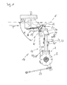
- tendon separator 10 for automatically separating tendons and / or tendon sections located on inner breast fillets in gutted and completely wing-free poultry bodies, in which both the breast fillet lying directly on the carcass 11 and the outer breast fillet covering the inner breast fillet are in their natural position, and which are transported ahead with the shoulder joints 12 in the transporting direction T along a transport path defining the transport plane E, the downwardly directed sternum 13 being aligned in the longitudinal direction of the transport direction T and parallel thereto, comprises a pair of release means 14, 15 for separating the tendons and / or tendon sections of the inner breast fillet.
- the two separating means 14, 15 lie on opposite sides of the transport path.
- Such a tendon separation device 10, which is usually attached to a frame, a frame or a housing of a processing device 16, which will be described below, is characterized according to the invention in that the separating means 14, 15 are formed as a razor 17, 18 wherein each sticking knife 17, 18 is designed and set up to carry out at least two cutting movements of different directions of movement and the two cutting movements can be superimposed.
- Stinging knives 17, 18 are to be understood as meaning all separating tools which on the one hand ensure punctual or targeted penetration into the poultry body and on the other hand have at least one cutting edge 19, 20 by means of which a separating cut can be made.
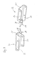
- each sticking knife 17, 18 is arranged on a support element 21, 22 pivotable about a rotation axis K, which in turn is connected to a pivotable about a rotation axis Z pivot lever 23, 24 is fixed.
- the support member 21, 22 is a U-shaped profile with a cover plate 25 and side walls 26, 27.
- On the cover plate 25 is a retaining tab 28 for the piercing knife 17, 18 is formed.
- the retaining tab 28 is preferably perpendicular to the cover plate 25, but may also be aligned at a different angle obliquely to the cover plate 25.
- the carrier element 21, 22 may be formed in one piece or in several parts.
- the support member 21, 22 may be formed in other ways, for example, as a frame structure, lever member, flange solution or the like.
- the carrier element 21, 22 is pivotably arranged on a flange element 29.
- the flange element 29 comprises a pivot pin 30 on which the carrier element 21, 22 is mounted with its side walls 26, 27 rotatable about the rotation axis K.
- Other solutions for pivoting the support element 21, 22 about the axis of rotation K such. a wave constructions, a hinge solution or the like, but are also usable.
- the pivoting levers 23, 24 are in the embodiment shown simple profiles. At a free end of the pivot lever 23, 24, the support elements 21, 22 are attached. At the opposite end of the pivot lever 23, 24 are rotatably mounted about the rotation axis Z. For this, e.g.
- pivot lever 23, 24 may be arranged a pivot pin 57 which is mounted in a carrier 42.
- Other solutions for pivoting the pivot lever 23, 24 about the axis of rotation Z such. a wave constructions, a hinge solutions or the like, but are also used.
- the axis of rotation Z is preferably aligned parallel to the transport plane E and in the direction of the transport direction T, such that the piercing knife 17, 18 can be moved transversely to the transport direction T towards and away from the poultry body.
- transport plane in the present case is not a two-dimensional plane in the strictly mathematical sense. Since the poultry bodies have a certain thickness, the term is only to be understood as meaning that the poultry bodies are transported parallel to a conveyor of the processing apparatus 16 in the horizontal direction (see, for example, US Pat FIG. 1 or 3 ).
- the movement of the stingers 17, 18 transverse to Transport direction T includes in addition to a perpendicular to the transport direction T on the poultry body striking stinging knives 17, 18 expressly also an impact of the sticking knives 17, 18 on the poultry body at an angle not equal to 90 °, ie at an acute angle.
- pivoting about the rotation axis Z enables the advancing movement of the sticking knives 17, 18 from a waiting position in which the sticking knives 17, 18 allow collision-free transporting of the poultry bodies through the chordal separator 10, into a separating position in which the stingers 17, 18 are located within the poultry body for performing the separating cut, and back.
- the axis of rotation Z may also be inclined at an acute angle to the transport plane E and / or to the transport direction T.
- the axis of rotation K is preferably aligned parallel to the transport direction T and at an angle ⁇ to the transport plane E, such that the piercing knife 17, 18 with a vertical component to the transport plane E is movable up or down.
- This tilting or pitching movement of the lancing blade 17, 18 at the angle ⁇ allows the lancing blades 17, 18 to make a cutting movement with a horizontal and a vertical component. This means that it results in a cutting line intersecting the transport plane E, which ensures the separation of the chords or tendon sections from the inner breast fillet.
- the angle ⁇ is greater than 0 ° and less than 90 ° and preferably between 30 ° and 50 °. Particularly preferred is an angle ⁇ between 35 ° and 45 °.
- the axis of rotation K may also be inclined at an acute angle to the transport direction T.
- the pulling separating cut is achieved, with which the tendons or tendon sections of the inner breast fillets are separated while the inner breast fillets are still in their original, natural position on the carcass 11.
- the inclination of the support element 21, 22 relative to the pivot lever 23, 24 for changing the angle ⁇ adjustable e.g. the flange 29 have a correspondingly shaped slot 31.
- This arcuate slot 31 simultaneously forms a stop for the adjustment movement.
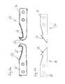
- the sticking knives 17, 18 have cutting blades 32, 33, which are preferably formed approximately triangular. Furthermore, the sticking knives 17, 18 comprise a fastening body 34, 35, which is preferably formed integrally with the cutting blades 32, 33. With the fastening body 34, 35, the sticking knives 17, 18 fixed but releasably attached to the retaining tabs 28.
- the cutting blades 32, 33 have their sharp cutting edges 19, 20 on one side. On the side facing away from the cutting edges 19, 20 side guide edges 36, 37 are formed blunt.
- the sharp cutting edges 19, 20 of the cutting blades 32, 33 point in the direction of the clavicles 38 of the carcass 11.
- the FIGS. 6 a + b show further preferred embodiments of the sticking knives 17, 18.
- the sticking knives 17, 18 according to the FIG. 6a have a rounded "threading area" 60.
- the tip of the stinging knives 17, 18 which penetrates the poultry body first is made blunt.
- the cutting blades 64, 65 of the sticking knives 17, 18 are preferably formed slightly curved.
- the cutting blades 61, 62 of in FIG. 6b shown sticking knives 17, 18 are hook-shaped, in this embodiment, the first thing in the poultry body end tip is sharp-edged.
- the lancing knives 17, 18 are associated with at least two servomotors 40, 41, by means of the sticking knives 17, 18 are movable from a waiting position to a cutting or separating position and vice versa and to exercise the cutting movements.
- the servomotors 40, 41 other suitable drive means can also be used.
- Each sticking knife 17, 18 can be controlled individually.
- the two pivot levers 23, 24 are pivotally mounted on a common carrier 42.
- the support 42 is preferably designed so as to be pivotable about a rotation axis S which runs parallel to the transport plane E and transversely to the transport direction T, for example by means of a servomotor 63.
- This pivotal movement about the axis of rotation S which allows a quasi-limited “running” of the sticking knives 17, 18, is superimposed on the pivoting movements about the axes of rotation Z and K, so that a "liquid” or continuous separation movement of the sticks 17, 18 is achieved
- the tracking movement can also be linear, for example by means of a carriage or the like.
- the sticking knives 17, 18 can be controlled individually and individually.
- the stinging knives can also be synchronized with one another.
- One possibility is the electronic synchronization.
- the sticking knives 17, 18 are mechanically connected to one another via a synchronization linkage 44.
- Both pivot levers 23, 24 are each assigned a synchronization rod 45, 46, which can be actuated synchronously by the servomotor 40.
- the two support elements 21, 22 is also associated with a respective synchronization rod 47, 48, which are synchronously actuated by the servo motor 41.
- the synchronization can also be realized in other ways.
- an actuating rod 54 is also provided for the rotation about the rotation axis S, which can also be connected to a servo motor or another actuating means.
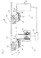
- the invention further relates to a processing device 16.
- a processing device 16 for removing the meat from gutted and completely wing-free poultry bodies is shown only schematically, which comprises processing stations 50 arranged in a processing line 49.
- the processing device 16 comprises a driven conveyor 51 with holding devices 43 arranged in series along the processing line 49 for transporting poultry bodies supported on the holding devices 43 and passing them to the processing stations 50.
- at least one measuring device 52 emitting measuring signals for detecting individual features is provided Poultry body during its promotion and a measuring device received the control means 53 for controlling the operation of the processing stations 50 part of the processing device 16.
- One of the processing stations 50 is a tendon separator 10, as described in detail in the invention above.
- a Congresssattelter on the holding device 43 poultry body (carcass with breast fillets) is transported by means of the conveyor 51 along the transport path in the transport plane E in the transport direction T at several processing stations 50 over (see, eg FIG. 3 ).
- the breast fillets have been omitted for the sake of clarity, in particular with regard to the carcass.
- the breast fillets ie the inner breast fillets and the outer breast fillets, both in the region of the measuring device 52 and in the region of the tendon separator 10, are still in their original, natural position on the carcass.
- Each poultry body reaches the measuring device 52 with the shoulder joints 12 in front and the downwardly directed sternum 13, which is aligned in the longitudinal direction of the transport direction T and parallel to this.
- the measuring device 52 for example, individual features are taken up to the poultry body, preferably by measuring the position of the shoulder joints 12 (see in particular FIG. 3 ).
- the data / information determined by the measuring device 52 are received by the control device 53, processed and forwarded to the subsequent processing stations 50, in the exemplary embodiment, for example, to the tendon separating device 10, for their operation.
- the stinging knives 17, 18 Upon reaching the tendon separation device 10, the stinging knives 17, 18 are in their waiting position, so that the poultry body with the leading, the wishbone-forming key legs 38 can initially enter collision-free in the tendon separation device 10.
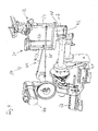
- the sticking knives 17, 18 are then controlled from the waiting position to the cutting position so that the sticking knives 17, 18 between raven bone 39 and collarbone 38 are inserted into the poultry body above the chord located on the inner breast fillet, without the outer breast fillet and the Inner breast fillet to hurt. Then a separation cut generated from two superimposed cutting movements by the stingers 17, 18 both obliquely downward from the Rabenbein 39 in the direction of the collarbone 38 and the poultry body are moved away to the outside.
- FIG. 5 shows the stingers 17, 18 in such a position between Rabenbein 39 and clavicle 38, wherein the sticking knives 17, 18 are already moved away from the Rabenbein 39.
- the resulting pulling cut on both sides of the poultry body separates the tendons located on the inner breast fillets while the inner breast fillets are still in their original, natural position.
- the sticking knives 17, 18 each move about at least two axes of rotation Z and K.
- the stick knives 17, 18 each side except for the Rabenbein 39 in the poultry body stabbed. This is ultimately an advancing movement of the sticking knives 17, 18 onto or into the poultry body.
- the sticking knives 17, 18 are then preferably with their blunt leading edge 36, 37 on the Rabenbein 39 at.
- the sticks 17, 18 move by a pivoting movement about the rotation axis K with respect to the transport plane E obliquely down along the fork leg, while the sticks 17, 18 are pivoted simultaneously about the rotation axis Z from the poultry body. From these superimposed movements, the pulling separating cut of the tendons or tendon sections results.
- the sticking knives 17, 18 may additionally be carried along with the poultry body in the transporting direction T during the separating cut just described.
- the entire unit consisting of pivoting levers 23, 24, support members 21, 22 and the adjoining lancing blades 17, 18, about the axis of rotation S
- a limited "running" of the Stechmesser 17, 18 can be achieved in the transport direction T, since the Pivoting movement also has a horizontal component.
- the resulting from the pivotal movement height changes by the vertical component can be compensated by the pivotal movements about the axes of rotation Z and K.
- the "running along” can also be linear, for example by means of a carriage.
Landscapes
- Life Sciences & Earth Sciences (AREA)
- Engineering & Computer Science (AREA)
- Wood Science & Technology (AREA)
- Zoology (AREA)
- Food Science & Technology (AREA)
- Processing Of Meat And Fish (AREA)
- Pretreatment Of Seeds And Plants (AREA)
Claims (16)
- Dispositif de séparation de tendons (10) pour séparer automatiquement les tendons et/ou portions de tendon qui se trouvent à l'intérieur du blanc sur des corps de volailles vidées et totalement débarrassées des ailes, corps de volaille sur lesquels l'intérieur du blanc qui repose directement sur la carcasse (11) ainsi que l'extérieur du blanc qui recouvre l'intérieur du blanc se trouvent dans leur position naturelle et qui sont transportés avec les articulations des épaules (12) à l'avant dans le sens du transport T le long d'un trajet de transport définissant le plan de transport E. Le sternum (13) dirigé vers le bas est orienté dans le sens longitudinal du sens du transport T et parallèlement à celui-ci. Le dispositif de séparation de tendons selon l'invention comprend une paire de moyens de séparation (14, 15) pour séparer les tendons et/ou portions de tendon de l'intérieur du blanc, les deux moyens de séparation (14, 15) se trouvant sur des côtés mutuellement opposés du trajet de transport des corps de volailles à traiter, et se caractérise en ce que les moyens de séparation (14, 15) sont réalisés sous la forme de couteaux à découper (17, 18). Chaque couteau à découper (17, 18) est configuré et agencé pour effectuer au moins deux mouvements de découpe dans des sens de déplacement différents et les deux mouvements de découpe peuvent se superposer.
- Dispositif de séparation de tendons selon la revendication 1, caractérisé en ce que chaque couteau à découper (17, 18) est disposé sur un élément de support (21, 22) pouvant pivoter autour d'un axe de rotation K. Chaque élément de support (21, 22) est fixé de l'autre côté à un levier pivotant (23, 24) qui pivote autour d'un axe de rotation Z.
- Dispositif de séparation de tendons selon la revendication 2, caractérisé en ce que l'axe de rotation Z est positionné parallèlement au plan de transport E et en direction du sens du transport T, de sorte que le couteau à découper (17, 18) puisse se déplacer en se rapprochant et en s'écartant des corps de volailles transversalement par rapport au sens du transport T et l'axe de rotation K est positionné parallèlement au sens du transport T et dans un angle α par rapport au plan de transport E, de sorte que le couteau à découper (17, 18) puisse de déplacer vers le haut ou vers le bas avec une composante verticale par rapport au plan de transport E.
- Dispositif de séparation de tendons selon la revendication 2 ou 3, caractérisé en ce que l'inclinaison de l'élément de support (21, 22) par rapport au levier pivotant (23, 24) est réglable pour modifier l'angle α.
- Dispositif de séparation de tendons selon l'une des revendications 2 à 4, caractérisé en ce que les couteaux de découpe (17, 18) doivent présenter des lames de découpe (32, 33) à peu près triangulaires et être fixés solidement mais de manière amovible à l'élément de support (21, 22) de sorte que l'arête de coupe aiguisée (19, 20) de la lame de découpe (32, 33) est agencée du côté opposé au coracoïde (39) et placée dans le sens de la clavicule (38).
- Dispositif de séparation de tendons selon l'une des revendications 1 à 5, caractérisé en ce que les couteaux à découper (17, 18) sont associés à au moins deux servomoteurs (40, 41), au moyen desquels les couteaux à découper (17, 18) peuvent se déplacer d'une position d'attente à une position de découpe et inversement ainsi que pour effectuer les mouvements de découpe.
- Dispositif de séparation de tendons selon l'une des revendications 2 à 6, caractérisé en ce que les deux leviers pivotants (23, 24) sont montés sur un support commun (42) de manière à pouvoir pivoter.
- Dispositif de séparation de tendons selon la revendication 7, caractérisé en ce que le support (42) est conçu pour pivoter autour d'un axe de rotation S évoluant parallèlement au plan de transport E et transversalement à la direction du transport T, le mouvement de pivotement autour de l'axe de rotation S et les mouvements de pivotement autour des axes de rotation Z et K étant superposables.
- Dispositif de séparation de tendons selon l'une des revendications 1 à 8, caractérisé en ce que les deux couteaux à découper (17, 18) sont en liaison opérationnelle l'un avec l'autre par une tringlerie de synchronisation (44).
- Dispositif de séparation de tendons selon la revendication 9, caractérisé en ce que les deux leviers pivotants (23, 24) sont chacun associés à une barre de synchronisation (45, 46), actionnées en synchronisme par un servomoteur (40) et que les deux éléments de support (21, 22) sont chacun associés à une barre de synchronisation (47, 48), actionnées en synchronisme par un servomoteur (41).
- Dispositif de traitement (16) pour retirer la viande sur des corps de volailles vidées et totalement débarrassées des ailes comprenant des postes de traitement (50) disposés sur une ligne de traitement (49), un convoyeur motorisé (51) avec, le long de la ligne de traitement (49), des dispositifs de maintien alignés (43) pour transporter les corps de volailles reposant sur les dispositifs de maintien (43) et faire passer ceux-ci aux postes de traitement (50), au moins un dispositif de mesure (52) déclenchant des signaux de mesure pour détecter les caractéristiques individuelles des corps de volailles pendant leur transport ainsi qu'un moyen de commande (53) recevant les signaux de mesure pour commander le fonctionnement des postes de traitement (50) ainsi qu'un dispositif de séparation de tendons (10) comme poste de traitement (50) pour séparer automatiquement les tendons et/ou portions de tendon qui se trouvent à l'intérieur du blanc, caractérisé en ce que ledit dispositif de séparation de tendons (10) est conçu selon l'une des revendications 1 à 10.
- Procédé de séparation automatique des tendons et/ou portions de tendon qui se trouvent à l'intérieur du blanc sur des corps de volailles vidées et totalement débarrassées des ailes, corps de volaille sur lesquels l'intérieur du blanc qui repose directement sur la carcasse (11) ainsi que l'extérieur du blanc qui recouvre l'intérieur du blanc se trouvent dans leur position naturelle, procédé caractérisé par les étapes suivantes :- le transport des corps de volailles avec les articulations des épaules (12) à l'avant dans le sens du transport T le long d'un trajet de transport définissant le plan de transport E. Le sternum (13) dirigé vers le bas est orienté dans le sens longitudinal du sens du transport T et parallèlement à celui-ci,- l'insertion de couteaux à découper (17, 18) dans les deux côtés des corps de volailles au-dessus du tendon et/ou de la portion de tendon, et- l'exécution d'au moins deux mouvements de découpe dans des sens de déplacement différents avec chacun des couteaux à découper (17, 18), les deux mouvements de découpe se superposant l'un l'autre.
- Procédé selon la revendication 12, caractérisé en ce que les caractéristiques individuelles des corps de volailles sont détectées et utilisées pour commander les couteaux à découper (17, 18).
- Procédé selon la revendication 12 ou 13, caractérisé en ce que les couteaux à découper (17, 18) se déplacent chacun autour d'au moins deux axes de rotation Z et K pour exercer des mouvements d'introduction et de découpe.
- Procédé selon l'une des revendications 12 à 14, caractérisé en ce que les couteaux de découpe (17, 18) s'enfoncent chacun latéralement jusqu'au coracoïde (39) dans les corps de volailles de sorte que les couteaux de découpe (17, 18) avec leur arête de guidage émoussée (36, 37) se placent près du coracoïde (39) pour ensuite être extraits du corps de la volaille le long de la clavicule avec leur arête de coupe aiguisée (19, 20) opposée à la clavicule (38) au moyen de mouvements de découpe superposés dirigés vers le bas et l'extérieur en oblique par rapport au plan de transport E .
- Procédé selon l'une des revendications 12 à 15, caractérisé en ce que les couteaux de découpe (17, 18) sont au moins partiellement emportés pendant l'exécution des mouvements de découpe avec le corps de la volaille dans le sens du transport T.
Priority Applications (9)
| Application Number | Priority Date | Filing Date | Title |
|---|---|---|---|
| ES12153328T ES2531395T3 (es) | 2012-01-31 | 2012-01-31 | Dispositivo de separación de tendones, así como dispositivo de tratamiento con un dispositivo de separación de tendones de este tipo y procedimiento para la separación automática de tendones y/o porciones de tendón que se encuentran en filetes interiores de pechuga |
| EP20120153328 EP2622962B1 (fr) | 2012-01-31 | 2012-01-31 | Dispositif de séparation de tendons ainsi que dispositif de traitement doté d'un tel dispositif de séparation de tendons et procédé de séparation automatique de tendons et/ou sections de tendons se trouvant sur des filets intérieure |
| DK12153328T DK2622962T3 (en) | 2012-01-31 | 2012-01-31 | Sinew separating and processing device having such a sinew separating apparatus and process for the automatic cutting of tendons and / or tendon section, which is located on inderbrystfileter |
| AU2012367911A AU2012367911B2 (en) | 2012-01-31 | 2012-12-03 | Sinew removal device, processing device having such a sinew removal device, and method for the automatic removal of sinews and/or sinew portions situated on inner breast fillets |
| US14/375,814 US9433223B2 (en) | 2012-01-31 | 2012-12-03 | Sinew removal device, processing device having such a sinew removal device, and method for the automatic removal of sinews and/or sinew portions situated on inner breast fillets |
| CN201280068420.2A CN104105406B (zh) | 2012-01-31 | 2012-12-03 | 肌腱去除装置,具有该肌腱去除装置的加工装置以及自动去除内侧胸部肌肉上的肌腱和/或肌腱部的方法 |
| PCT/EP2012/074225 WO2013113428A1 (fr) | 2012-01-31 | 2012-12-03 | Dispositif de séparation de tendons et dispositif de traitement équipé dudit dispositif de séparation de tendons et procédé de séparation automatique de tendons et/ou portions de tendon qui se trouvent à l'intérieur du blanc de volaille |
| CA2861942A CA2861942C (fr) | 2012-01-31 | 2012-12-03 | Dispositif de separation de tendons et dispositif de traitement equipe dudit dispositif de separation de tendons et procede de separation automatique de tendons et/ou portions detendon qui se trouvent a l'interieur du blanc de volaille |
| BR112014018166-7A BR112014018166B1 (pt) | 2012-01-31 | 2012-12-03 | aparelho para remoção de tendões, dispositivo de processamento tendo o referido aparelho para remoção de tendões, e método para remoção automática de tendões e/ou partes de tendões situados nos filés de peito internos |
Applications Claiming Priority (1)
| Application Number | Priority Date | Filing Date | Title |
|---|---|---|---|
| EP20120153328 EP2622962B1 (fr) | 2012-01-31 | 2012-01-31 | Dispositif de séparation de tendons ainsi que dispositif de traitement doté d'un tel dispositif de séparation de tendons et procédé de séparation automatique de tendons et/ou sections de tendons se trouvant sur des filets intérieure |
Publications (2)
| Publication Number | Publication Date |
|---|---|
| EP2622962A1 EP2622962A1 (fr) | 2013-08-07 |
| EP2622962B1 true EP2622962B1 (fr) | 2014-12-17 |
Family
ID=47351602
Family Applications (1)
| Application Number | Title | Priority Date | Filing Date |
|---|---|---|---|
| EP20120153328 Not-in-force EP2622962B1 (fr) | 2012-01-31 | 2012-01-31 | Dispositif de séparation de tendons ainsi que dispositif de traitement doté d'un tel dispositif de séparation de tendons et procédé de séparation automatique de tendons et/ou sections de tendons se trouvant sur des filets intérieure |
Country Status (9)
| Country | Link |
|---|---|
| US (1) | US9433223B2 (fr) |
| EP (1) | EP2622962B1 (fr) |
| CN (1) | CN104105406B (fr) |
| AU (1) | AU2012367911B2 (fr) |
| BR (1) | BR112014018166B1 (fr) |
| CA (1) | CA2861942C (fr) |
| DK (1) | DK2622962T3 (fr) |
| ES (1) | ES2531395T3 (fr) |
| WO (1) | WO2013113428A1 (fr) |
Families Citing this family (8)
| Publication number | Priority date | Publication date | Assignee | Title |
|---|---|---|---|---|
| NL2017236B1 (en) * | 2016-07-25 | 2018-01-31 | Meyn Food Processing Tech Bv | Method and device for processing a carcass part of slaughtered poultry in a processing line |
| NL2017997B1 (en) * | 2016-12-14 | 2018-06-26 | Meyn Food Processing Tech Bv | Vent cutter and method for cutting loose tissue around a vent of poultry |
| EP3689147A1 (fr) * | 2019-01-29 | 2020-08-05 | Nordischer Maschinenbau Rud. Baader GmbH + Co. KG | Dispositif et procédé de séparation d'au moins un filet de poitrine d'une carcasse de volaille éviscérée ou d'une partie dudit filet de poitrine avec une carcasse de volaille ou d'un tendon relié à une partie dudit filet de poitrine ainsi qu'unité d'outil correspondant |
| CN111802433B (zh) * | 2019-04-12 | 2022-08-19 | 饶喜钊 | 肉类起筋器 |
| DE102019118268B3 (de) | 2019-07-05 | 2020-10-22 | Nordischer Maschinenbau Rud. Baader Gmbh + Co. Kg | Vorrichtung und Verfahren zum Schneiden in mindestens im Bereich eines Brustbeins einer Karkasse von Geflügelkörpern oder Teilen davon miteinander verbundenen Brustfilets entlang des Brustbeins |
| DE102020117866A1 (de) | 2020-07-07 | 2022-01-13 | Nordischer Maschinenbau Rud. Baader Gmbh + Co. Kg | Vorrichtung und Verfahren zur automatischen Verarbeitung von entweideten Geflügelkörpern oder Teilen davon |
| CN112006077A (zh) * | 2020-09-21 | 2020-12-01 | 潍坊鑫都食品有限公司 | 一种鸡小胸去筋装置 |
| CN113826681A (zh) * | 2021-10-25 | 2021-12-24 | 徐州恒阳禽业有限公司 | 一种自动夹紧且往复刮肉的鸡腿剃肉装置 |
Family Cites Families (12)
| Publication number | Priority date | Publication date | Assignee | Title |
|---|---|---|---|---|
| CN85102729A (zh) * | 1985-04-15 | 1986-10-15 | 斯托克Pmt公司 | 用于切割屠宰后的禽类身体的一部分的方法及装置 |
| US4873746A (en) * | 1988-01-25 | 1989-10-17 | Simon-Johnson Company | Method and apparatus for removing breast meat from poultry carcass |
| DE3811317A1 (de) * | 1988-04-02 | 1989-10-19 | Nordischer Maschinenbau | Verfahren zum gewinnen des fleisches von den koerpern geschlachteten gefluegels und vorrichtung zur durchfuehrung des verfahrens |
| US5228881A (en) * | 1991-04-03 | 1993-07-20 | Gordex Corporation | Poultry leg boning apparatus |
| US5314374A (en) * | 1993-06-14 | 1994-05-24 | Jay Koch | Apparatus for removing tenders from a poultry carcass |
| US5395283A (en) * | 1994-03-23 | 1995-03-07 | Gasbarro; Geno N. | Automatic tendon removal apparatus |
| DE19848498A1 (de) * | 1998-10-21 | 2000-05-04 | Nordischer Maschinenbau | Filetiervorrichtung |
| NL1012683C2 (nl) * | 1999-07-23 | 2001-01-24 | Stork Pmt | Werkwijze voor het winnen van een binnenfilet van een gevogeltekarkasdeel, en inrichting voor het bewerken van het gevogeltekarkasdeel. |
| JP3497476B2 (ja) * | 2001-01-30 | 2004-02-16 | 株式会社前川製作所 | 中抜き屠体のハービング方法とその装置 |
| US6890251B2 (en) * | 2002-10-15 | 2005-05-10 | Tyson Foods, Inc. | Apparatus and method for removing poultry tenders |
| CA2546456A1 (fr) * | 2003-06-20 | 2004-12-29 | Mayekawa Mfg. Co., Ltd. | Methode et appareil pour separer la chair du haut de cuisse et le sot-l'y-laisse |
| DE102004003922B3 (de) * | 2004-01-27 | 2005-03-10 | Georg Krause | Einrichtung zum Entfernen von Sehnen |
-
2012
- 2012-01-31 EP EP20120153328 patent/EP2622962B1/fr not_active Not-in-force
- 2012-01-31 ES ES12153328T patent/ES2531395T3/es active Active
- 2012-01-31 DK DK12153328T patent/DK2622962T3/en active
- 2012-12-03 WO PCT/EP2012/074225 patent/WO2013113428A1/fr active Application Filing
- 2012-12-03 CN CN201280068420.2A patent/CN104105406B/zh not_active Expired - Fee Related
- 2012-12-03 CA CA2861942A patent/CA2861942C/fr active Active
- 2012-12-03 BR BR112014018166-7A patent/BR112014018166B1/pt not_active IP Right Cessation
- 2012-12-03 AU AU2012367911A patent/AU2012367911B2/en not_active Ceased
- 2012-12-03 US US14/375,814 patent/US9433223B2/en active Active
Also Published As
| Publication number | Publication date |
|---|---|
| BR112014018166B1 (pt) | 2021-02-02 |
| US9433223B2 (en) | 2016-09-06 |
| BR112014018166A2 (fr) | 2017-06-20 |
| DK2622962T3 (en) | 2015-03-09 |
| BR112014018166A8 (pt) | 2019-01-29 |
| AU2012367911A1 (en) | 2014-08-28 |
| WO2013113428A1 (fr) | 2013-08-08 |
| CA2861942C (fr) | 2016-01-12 |
| US20150105008A1 (en) | 2015-04-16 |
| AU2012367911B2 (en) | 2015-07-16 |
| CA2861942A1 (fr) | 2013-08-08 |
| CN104105406B (zh) | 2016-02-24 |
| CN104105406A (zh) | 2014-10-15 |
| EP2622962A1 (fr) | 2013-08-07 |
| ES2531395T3 (es) | 2015-03-13 |
Similar Documents
| Publication | Publication Date | Title |
|---|---|---|
| EP2622962B1 (fr) | Dispositif de séparation de tendons ainsi que dispositif de traitement doté d'un tel dispositif de séparation de tendons et procédé de séparation automatique de tendons et/ou sections de tendons se trouvant sur des filets intérieure | |
| EP2207426B1 (fr) | Dispositif pour enlever par découpage les arêtes latérales de poissons étêtés, abattus et ouverts au niveau de leur cavité abdominale et machine à fileter pour prélever les filets de poissons étêtés, abattus et ouverts au niveau de leur cavité abdominale comprenant un tel dispositif | |
| DE602004006451T2 (de) | System zum Filetieren von Geflügel | |
| DE69706349T3 (de) | Vorrichtung zum Filettieren von Geflügelbrust | |
| EP2456316B1 (fr) | Dispositif et procédé permettant de détacher complètement des filets des arêtes de poissons vidés et étêtés en tranchant une chair laissée par d'autres outils | |
| DE3811317C2 (fr) | ||
| DD254322A5 (de) | Vorrichtung zum gewinnen fleischgraetenfreier filets von fischen | |
| DE2946042C2 (de) | Vorrichtung zum Abtrennen der Filets von Fischen | |
| EP3409125B1 (fr) | Dispositif d'extraction des arêtes latérales à partir de filets de poisson, machine de filetage avec un tel dispositif et procédé d'extraction des arêtes latérales à partir de filets de poisson | |
| EP2512256B1 (fr) | Dispositif et procédé pour enlever le cartilage costal d'une volaille | |
| WO2012041610A1 (fr) | Dispositif et procédé destiné à détacher intégralement au moins une partie du cartilage de poitrine à partir d'une carcasse de volaille libérée de son blanc | |
| WO2013139369A1 (fr) | Procédé d'enlèvement mécanique des arêtes de chair des filets de poisson et dispositif pour exécuter le procédé | |
| DE3518960C1 (de) | Vorrichtung zum Herstellen von grätenfreien Filets | |
| WO2020156825A1 (fr) | Dispositif et procédé pour la séparation d'au moins un filet de poitrine d'un corps de volailles vidé ou d'une partie de celui-ci ayant un tendon liant une carcasse du corps de volaille ou une partie de celui-ci ainsi qu'unité d'outil pour ce faire | |
| EP2420143B1 (fr) | Dispositif et procédé de coupe automatisée des ailes de corps de volailles | |
| EP3689148B1 (fr) | Dispositif et procédé permettant de maintenir une carcasse de volaille éviscérée ou une partie de ladite carcasse de volaille éviscérée lors du traitement dans un dispositif de traitement des carcasses de volailles éviscérées ou des parties des dites carcasses de volailles éviscérées | |
| DE2832329C2 (de) | Verfahren zum Filetieren von Fischen | |
| EP4108089A1 (fr) | Dispositif de découpe au travers des arêtes latérales des poissons étêtés, abattus et de préférence ouverts au niveau de leur cavité abdominale, ainsi que procédé et machine de filetage permettant de fileter des poissons étêtés, abattus et de préférence ouverts au niveau de leur cavité abdominale au moyen d'un tel dispositif | |
| EP4125396A1 (fr) | Élément de retenue destiné à l'agencement de dos ou parties de ces derniers de carcasses de volaille | |
| WO2021004778A1 (fr) | Dispositif et procédé de découpe, dans au moins une zone du sternum d'une carcasse de corps de volaille ou de parties de celui-ci, de filets de poitrine reliés entre eux le long du sternum | |
| DE19834523A1 (de) | Verfahren und eine Vorrichtung zur Verarbeitung von Fischen | |
| DE2543498C2 (de) | Verfahren und Vorrichtung zum maschinellen Gewinnen von fleischgrätenfreien Fischfilets | |
| DE10034936A1 (de) | Verfahren und Vorrichtung zum Filetieren geköpfter, geschlachteter und in ihrer Bauchhöhle geöffneter Fische | |
| DE2543498B1 (de) | Verfahren und vorrichtung zum maschinellen gewinnen von fleischgraetenfreien fischfilets | |
| DE2832329B2 (fr) |
Legal Events
| Date | Code | Title | Description |
|---|---|---|---|
| PUAI | Public reference made under article 153(3) epc to a published international application that has entered the european phase |
Free format text: ORIGINAL CODE: 0009012 |
|
| 17P | Request for examination filed |
Effective date: 20121205 |
|
| AK | Designated contracting states |
Kind code of ref document: A1 Designated state(s): AL AT BE BG CH CY CZ DE DK EE ES FI FR GB GR HR HU IE IS IT LI LT LU LV MC MK MT NL NO PL PT RO RS SE SI SK SM TR |
|
| AX | Request for extension of the european patent |
Extension state: BA ME |
|
| GRAP | Despatch of communication of intention to grant a patent |
Free format text: ORIGINAL CODE: EPIDOSNIGR1 |
|
| INTG | Intention to grant announced |
Effective date: 20140515 |
|
| GRAS | Grant fee paid |
Free format text: ORIGINAL CODE: EPIDOSNIGR3 |
|
| GRAA | (expected) grant |
Free format text: ORIGINAL CODE: 0009210 |
|
| AK | Designated contracting states |
Kind code of ref document: B1 Designated state(s): AL AT BE BG CH CY CZ DE DK EE ES FI FR GB GR HR HU IE IS IT LI LT LU LV MC MK MT NL NO PL PT RO RS SE SI SK SM TR |
|
| REG | Reference to a national code |
Ref country code: GB Ref legal event code: FG4D Free format text: NOT ENGLISH |
|
| REG | Reference to a national code |
Ref country code: CH Ref legal event code: EP |
|
| REG | Reference to a national code |
Ref country code: IE Ref legal event code: FG4D Free format text: LANGUAGE OF EP DOCUMENT: GERMAN |
|
| REG | Reference to a national code |
Ref country code: AT Ref legal event code: REF Ref document number: 701217 Country of ref document: AT Kind code of ref document: T Effective date: 20150115 Ref country code: FR Ref legal event code: PLFP Year of fee payment: 4 |
|
| REG | Reference to a national code |
Ref country code: DE Ref legal event code: R096 Ref document number: 502012001812 Country of ref document: DE Effective date: 20150129 |
|
| REG | Reference to a national code |
Ref country code: NL Ref legal event code: T3 |
|
| REG | Reference to a national code |
Ref country code: DK Ref legal event code: T3 Effective date: 20150302 |
|
| REG | Reference to a national code |
Ref country code: ES Ref legal event code: FG2A Ref document number: 2531395 Country of ref document: ES Kind code of ref document: T3 Effective date: 20150313 |
|
| PG25 | Lapsed in a contracting state [announced via postgrant information from national office to epo] |
Ref country code: FI Free format text: LAPSE BECAUSE OF FAILURE TO SUBMIT A TRANSLATION OF THE DESCRIPTION OR TO PAY THE FEE WITHIN THE PRESCRIBED TIME-LIMIT Effective date: 20141217 Ref country code: LT Free format text: LAPSE BECAUSE OF FAILURE TO SUBMIT A TRANSLATION OF THE DESCRIPTION OR TO PAY THE FEE WITHIN THE PRESCRIBED TIME-LIMIT Effective date: 20141217 Ref country code: NO Free format text: LAPSE BECAUSE OF FAILURE TO SUBMIT A TRANSLATION OF THE DESCRIPTION OR TO PAY THE FEE WITHIN THE PRESCRIBED TIME-LIMIT Effective date: 20150317 |
|
| REG | Reference to a national code |
Ref country code: LT Ref legal event code: MG4D |
|
| PG25 | Lapsed in a contracting state [announced via postgrant information from national office to epo] |
Ref country code: RS Free format text: LAPSE BECAUSE OF FAILURE TO SUBMIT A TRANSLATION OF THE DESCRIPTION OR TO PAY THE FEE WITHIN THE PRESCRIBED TIME-LIMIT Effective date: 20141217 Ref country code: SE Free format text: LAPSE BECAUSE OF FAILURE TO SUBMIT A TRANSLATION OF THE DESCRIPTION OR TO PAY THE FEE WITHIN THE PRESCRIBED TIME-LIMIT Effective date: 20141217 Ref country code: LV Free format text: LAPSE BECAUSE OF FAILURE TO SUBMIT A TRANSLATION OF THE DESCRIPTION OR TO PAY THE FEE WITHIN THE PRESCRIBED TIME-LIMIT Effective date: 20141217 Ref country code: GR Free format text: LAPSE BECAUSE OF FAILURE TO SUBMIT A TRANSLATION OF THE DESCRIPTION OR TO PAY THE FEE WITHIN THE PRESCRIBED TIME-LIMIT Effective date: 20150318 Ref country code: HR Free format text: LAPSE BECAUSE OF FAILURE TO SUBMIT A TRANSLATION OF THE DESCRIPTION OR TO PAY THE FEE WITHIN THE PRESCRIBED TIME-LIMIT Effective date: 20141217 |
|
| PG25 | Lapsed in a contracting state [announced via postgrant information from national office to epo] |
Ref country code: PT Free format text: LAPSE BECAUSE OF FAILURE TO SUBMIT A TRANSLATION OF THE DESCRIPTION OR TO PAY THE FEE WITHIN THE PRESCRIBED TIME-LIMIT Effective date: 20150417 Ref country code: SK Free format text: LAPSE BECAUSE OF FAILURE TO SUBMIT A TRANSLATION OF THE DESCRIPTION OR TO PAY THE FEE WITHIN THE PRESCRIBED TIME-LIMIT Effective date: 20141217 Ref country code: CZ Free format text: LAPSE BECAUSE OF FAILURE TO SUBMIT A TRANSLATION OF THE DESCRIPTION OR TO PAY THE FEE WITHIN THE PRESCRIBED TIME-LIMIT Effective date: 20141217 Ref country code: RO Free format text: LAPSE BECAUSE OF FAILURE TO SUBMIT A TRANSLATION OF THE DESCRIPTION OR TO PAY THE FEE WITHIN THE PRESCRIBED TIME-LIMIT Effective date: 20141217 Ref country code: EE Free format text: LAPSE BECAUSE OF FAILURE TO SUBMIT A TRANSLATION OF THE DESCRIPTION OR TO PAY THE FEE WITHIN THE PRESCRIBED TIME-LIMIT Effective date: 20141217 |
|
| REG | Reference to a national code |
Ref country code: CH Ref legal event code: PL |
|
| PG25 | Lapsed in a contracting state [announced via postgrant information from national office to epo] |
Ref country code: LU Free format text: LAPSE BECAUSE OF FAILURE TO SUBMIT A TRANSLATION OF THE DESCRIPTION OR TO PAY THE FEE WITHIN THE PRESCRIBED TIME-LIMIT Effective date: 20150131 Ref country code: PL Free format text: LAPSE BECAUSE OF FAILURE TO SUBMIT A TRANSLATION OF THE DESCRIPTION OR TO PAY THE FEE WITHIN THE PRESCRIBED TIME-LIMIT Effective date: 20141217 Ref country code: IS Free format text: LAPSE BECAUSE OF FAILURE TO SUBMIT A TRANSLATION OF THE DESCRIPTION OR TO PAY THE FEE WITHIN THE PRESCRIBED TIME-LIMIT Effective date: 20150417 |
|
| REG | Reference to a national code |
Ref country code: DE Ref legal event code: R097 Ref document number: 502012001812 Country of ref document: DE |
|
| PG25 | Lapsed in a contracting state [announced via postgrant information from national office to epo] |
Ref country code: MC Free format text: LAPSE BECAUSE OF FAILURE TO SUBMIT A TRANSLATION OF THE DESCRIPTION OR TO PAY THE FEE WITHIN THE PRESCRIBED TIME-LIMIT Effective date: 20141217 |
|
| PLBE | No opposition filed within time limit |
Free format text: ORIGINAL CODE: 0009261 |
|
| STAA | Information on the status of an ep patent application or granted ep patent |
Free format text: STATUS: NO OPPOSITION FILED WITHIN TIME LIMIT |
|
| PG25 | Lapsed in a contracting state [announced via postgrant information from national office to epo] |
Ref country code: LI Free format text: LAPSE BECAUSE OF NON-PAYMENT OF DUE FEES Effective date: 20150131 Ref country code: CH Free format text: LAPSE BECAUSE OF NON-PAYMENT OF DUE FEES Effective date: 20150131 |
|
| REG | Reference to a national code |
Ref country code: IE Ref legal event code: MM4A |
|
| 26N | No opposition filed |
Effective date: 20150918 |
|
| PG25 | Lapsed in a contracting state [announced via postgrant information from national office to epo] |
Ref country code: IT Free format text: LAPSE BECAUSE OF FAILURE TO SUBMIT A TRANSLATION OF THE DESCRIPTION OR TO PAY THE FEE WITHIN THE PRESCRIBED TIME-LIMIT Effective date: 20141217 |
|
| REG | Reference to a national code |
Ref country code: FR Ref legal event code: PLFP Year of fee payment: 5 |
|
| PG25 | Lapsed in a contracting state [announced via postgrant information from national office to epo] |
Ref country code: IE Free format text: LAPSE BECAUSE OF NON-PAYMENT OF DUE FEES Effective date: 20150131 |
|
| PG25 | Lapsed in a contracting state [announced via postgrant information from national office to epo] |
Ref country code: SI Free format text: LAPSE BECAUSE OF FAILURE TO SUBMIT A TRANSLATION OF THE DESCRIPTION OR TO PAY THE FEE WITHIN THE PRESCRIBED TIME-LIMIT Effective date: 20141217 |
|
| GBPC | Gb: european patent ceased through non-payment of renewal fee |
Effective date: 20160131 |
|
| PG25 | Lapsed in a contracting state [announced via postgrant information from national office to epo] |
Ref country code: GB Free format text: LAPSE BECAUSE OF NON-PAYMENT OF DUE FEES Effective date: 20160131 |
|
| PG25 | Lapsed in a contracting state [announced via postgrant information from national office to epo] |
Ref country code: MT Free format text: LAPSE BECAUSE OF FAILURE TO SUBMIT A TRANSLATION OF THE DESCRIPTION OR TO PAY THE FEE WITHIN THE PRESCRIBED TIME-LIMIT Effective date: 20141217 |
|
| REG | Reference to a national code |
Ref country code: FR Ref legal event code: PLFP Year of fee payment: 6 |
|
| PG25 | Lapsed in a contracting state [announced via postgrant information from national office to epo] |
Ref country code: SM Free format text: LAPSE BECAUSE OF FAILURE TO SUBMIT A TRANSLATION OF THE DESCRIPTION OR TO PAY THE FEE WITHIN THE PRESCRIBED TIME-LIMIT Effective date: 20141217 Ref country code: BG Free format text: LAPSE BECAUSE OF FAILURE TO SUBMIT A TRANSLATION OF THE DESCRIPTION OR TO PAY THE FEE WITHIN THE PRESCRIBED TIME-LIMIT Effective date: 20141217 Ref country code: HU Free format text: LAPSE BECAUSE OF FAILURE TO SUBMIT A TRANSLATION OF THE DESCRIPTION OR TO PAY THE FEE WITHIN THE PRESCRIBED TIME-LIMIT; INVALID AB INITIO Effective date: 20120131 |
|
| PG25 | Lapsed in a contracting state [announced via postgrant information from national office to epo] |
Ref country code: CY Free format text: LAPSE BECAUSE OF FAILURE TO SUBMIT A TRANSLATION OF THE DESCRIPTION OR TO PAY THE FEE WITHIN THE PRESCRIBED TIME-LIMIT Effective date: 20141217 |
|
| PG25 | Lapsed in a contracting state [announced via postgrant information from national office to epo] |
Ref country code: BE Free format text: LAPSE BECAUSE OF NON-PAYMENT OF DUE FEES Effective date: 20150131 |
|
| PG25 | Lapsed in a contracting state [announced via postgrant information from national office to epo] |
Ref country code: TR Free format text: LAPSE BECAUSE OF FAILURE TO SUBMIT A TRANSLATION OF THE DESCRIPTION OR TO PAY THE FEE WITHIN THE PRESCRIBED TIME-LIMIT Effective date: 20141217 |
|
| REG | Reference to a national code |
Ref country code: FR Ref legal event code: PLFP Year of fee payment: 7 |
|
| REG | Reference to a national code |
Ref country code: AT Ref legal event code: MM01 Ref document number: 701217 Country of ref document: AT Kind code of ref document: T Effective date: 20170131 |
|
| PG25 | Lapsed in a contracting state [announced via postgrant information from national office to epo] |
Ref country code: AT Free format text: LAPSE BECAUSE OF NON-PAYMENT OF DUE FEES Effective date: 20170131 |
|
| PG25 | Lapsed in a contracting state [announced via postgrant information from national office to epo] |
Ref country code: MK Free format text: LAPSE BECAUSE OF FAILURE TO SUBMIT A TRANSLATION OF THE DESCRIPTION OR TO PAY THE FEE WITHIN THE PRESCRIBED TIME-LIMIT Effective date: 20141217 |
|
| PG25 | Lapsed in a contracting state [announced via postgrant information from national office to epo] |
Ref country code: AL Free format text: LAPSE BECAUSE OF FAILURE TO SUBMIT A TRANSLATION OF THE DESCRIPTION OR TO PAY THE FEE WITHIN THE PRESCRIBED TIME-LIMIT Effective date: 20141217 |
|
| PGFP | Annual fee paid to national office [announced via postgrant information from national office to epo] |
Ref country code: DK Payment date: 20220121 Year of fee payment: 11 Ref country code: DE Payment date: 20220120 Year of fee payment: 11 |
|
| PGFP | Annual fee paid to national office [announced via postgrant information from national office to epo] |
Ref country code: NL Payment date: 20220120 Year of fee payment: 11 Ref country code: FR Payment date: 20220120 Year of fee payment: 11 Ref country code: ES Payment date: 20220216 Year of fee payment: 11 |
|
| REG | Reference to a national code |
Ref country code: DE Ref legal event code: R119 Ref document number: 502012001812 Country of ref document: DE |
|
| REG | Reference to a national code |
Ref country code: DK Ref legal event code: EBP Effective date: 20230131 |
|
| REG | Reference to a national code |
Ref country code: NL Ref legal event code: MM Effective date: 20230201 |
|
| PG25 | Lapsed in a contracting state [announced via postgrant information from national office to epo] |
Ref country code: NL Free format text: LAPSE BECAUSE OF NON-PAYMENT OF DUE FEES Effective date: 20230201 Ref country code: DE Free format text: LAPSE BECAUSE OF NON-PAYMENT OF DUE FEES Effective date: 20230801 |
|
| PG25 | Lapsed in a contracting state [announced via postgrant information from national office to epo] |
Ref country code: FR Free format text: LAPSE BECAUSE OF NON-PAYMENT OF DUE FEES Effective date: 20230131 |
|
| PG25 | Lapsed in a contracting state [announced via postgrant information from national office to epo] |
Ref country code: DK Free format text: LAPSE BECAUSE OF NON-PAYMENT OF DUE FEES Effective date: 20230131 |
|
| REG | Reference to a national code |
Ref country code: ES Ref legal event code: FD2A Effective date: 20240403 |
|
| PG25 | Lapsed in a contracting state [announced via postgrant information from national office to epo] |
Ref country code: ES Free format text: LAPSE BECAUSE OF NON-PAYMENT OF DUE FEES Effective date: 20230201 |
|
| PG25 | Lapsed in a contracting state [announced via postgrant information from national office to epo] |
Ref country code: ES Free format text: LAPSE BECAUSE OF NON-PAYMENT OF DUE FEES Effective date: 20230201 |