EP2619151B1 - Verfahren zum geregelten betrieb eines regenerativ beheizten industrieofens, steuereinrichtung und industrieofen mit steuereinrichtung - Google Patents
Verfahren zum geregelten betrieb eines regenerativ beheizten industrieofens, steuereinrichtung und industrieofen mit steuereinrichtung Download PDFInfo
- Publication number
- EP2619151B1 EP2619151B1 EP11767207.1A EP11767207A EP2619151B1 EP 2619151 B1 EP2619151 B1 EP 2619151B1 EP 11767207 A EP11767207 A EP 11767207A EP 2619151 B1 EP2619151 B1 EP 2619151B1
- Authority
- EP
- European Patent Office
- Prior art keywords
- regenerator
- temperature
- combustion air
- control
- furnace
- Prior art date
- Legal status (The legal status is an assumption and is not a legal conclusion. Google has not performed a legal analysis and makes no representation as to the accuracy of the status listed.)
- Active
Links
Images



Classifications
-
- C—CHEMISTRY; METALLURGY
- C03—GLASS; MINERAL OR SLAG WOOL
- C03B—MANUFACTURE, SHAPING, OR SUPPLEMENTARY PROCESSES
- C03B5/00—Melting in furnaces; Furnaces so far as specially adapted for glass manufacture
- C03B5/16—Special features of the melting process; Auxiliary means specially adapted for glass-melting furnaces
- C03B5/24—Automatically regulating the melting process
-
- G—PHYSICS
- G05—CONTROLLING; REGULATING
- G05D—SYSTEMS FOR CONTROLLING OR REGULATING NON-ELECTRIC VARIABLES
- G05D23/00—Control of temperature
- G05D23/19—Control of temperature characterised by the use of electric means
- G05D23/1927—Control of temperature characterised by the use of electric means using a plurality of sensors
- G05D23/193—Control of temperature characterised by the use of electric means using a plurality of sensors sensing the temperaure in different places in thermal relationship with one or more spaces
- G05D23/1931—Control of temperature characterised by the use of electric means using a plurality of sensors sensing the temperaure in different places in thermal relationship with one or more spaces to control the temperature of one space
-
- Y—GENERAL TAGGING OF NEW TECHNOLOGICAL DEVELOPMENTS; GENERAL TAGGING OF CROSS-SECTIONAL TECHNOLOGIES SPANNING OVER SEVERAL SECTIONS OF THE IPC; TECHNICAL SUBJECTS COVERED BY FORMER USPC CROSS-REFERENCE ART COLLECTIONS [XRACs] AND DIGESTS
- Y02—TECHNOLOGIES OR APPLICATIONS FOR MITIGATION OR ADAPTATION AGAINST CLIMATE CHANGE
- Y02P—CLIMATE CHANGE MITIGATION TECHNOLOGIES IN THE PRODUCTION OR PROCESSING OF GOODS
- Y02P40/00—Technologies relating to the processing of minerals
- Y02P40/50—Glass production, e.g. reusing waste heat during processing or shaping
Definitions
- the invention relates to a method for the controlled operation of a regeneratively heated industrial furnace, in particular with a melting tank, in particular for glass, according to the preamble of claim 1.
- the invention also relates to an industrial furnace according to the preamble of claim 15th
- an industrial furnace is not limited to use in glassmaking.
- an industrial furnace of the type mentioned above can also be used in metal production or the like.
- a regenerative industrial furnace of the type mentioned has proven to be particularly suitable in the glass production for melting glass.
- GB 1,188,256 a method for the controlled operation of a regeneratively heated industrial furnace with a temperature control wherein a control is provided for a cycle of the fire periods of the burners.
- a controller may specify control signals when a temperature or a temperature difference has reached a predetermined value.
- FR 1,260,888 discloses a method of operating a regenerative industrial furnace in which, for example, after a disturbance there may be a unilateral increase in the temperature of regenerator chambers, for example, one of the temperatures being even higher than the others by an allowable difference.
- the hottest regenerator chambers are then charged only for the minimum amount of time, for example 6 minutes, while the chambers in front of the cooler are traversed by the flue gas for a period equal to the maximum duration (for example 15 minutes).
- the regenerator chambers are charged symmetrically at the same temperatures.
- WO 02/48057 A1 describes a method for the measurement and simple and fixed-structured control of quality-determining parameters of a glass bath, in which the batch cover, the aggregate aggregation, the position of the thermal centers of heat sinks and sources of the glass bath surface and the flames are optically measured.
- a mixture cover is compared as setpoint in a subsequent control and adjusted by fuel, fuel distribution, burner upstream, auxiliary heater power or bubbling throughput.
- a control loop regulates the batching level.
- this method advantageously uses the batching degree as an indication of the surface area of molten material being formed on the surface of the melt, and this as an indicator of the actual heat transfer at a given melting rate.
- the mixture cover determined in this way can be determined in an even better manner.
- the approach proposed therein of analysis is susceptible to drifting image brightness and can be further improved in terms of its specificity.
- the invention begins, the object of which is to specify an improved method for the controlled operation of a regeneratively heated industrial furnace, in particular with a melting tank, in particular for glass, as well as an improved regeneratively heated industrial furnace.
- the object is achieved by the invention with a method of the type mentioned, in which according to the invention the features of the characterizing part of claim 1 are provided.
- the invention leads to the solution of the task to an industrial furnace according to claim 15.
- Under fuel is to be understood in particular fuel gas.
- Other fuels such as oil, eg. As fuel oil, or the like are also possible to operate an industrial furnace. Also mixtures of fuel gas and fuel oil are possible.
- An injector is to be understood in particular as a injection device which is designed to inject fuel directly in front of a furnace chamber in a feed section or in the furnace chamber, in particular separately from combustion air. A mixture of combustion air and fuel is provided only in the oven room.
- the furnace chamber has in particular an upper furnace and a lower furnace.
- a sub-furnace has in particular a glass melting tank or the like.
- regenerators as left and right regenerators are not intended to be limiting as to the location of the same and follow the general technical usage.
- the names can also be chosen differently, eg. B. as a first and second regenerator.
- the regenerators may be arranged with respect to a glass melting tank in the flow direction or transversely to the direction of flow of the glass.
- a single regenerator may be associated with a number of injectors.
- a regenerator may also be understood to mean a regenerator section or the like associated with a single injector.
- the first and second control loops are initially executable independently of each other and can thus act independently on the controlled system.
- the first and second control loops can also be coupled; e.g. via the temperature controller or the symmetry controller.
- a first adjustable control variable in the form of a fuel flow and / or a combustion air flow is set via an actuator assigned to the first regulator. It is understood that with controlled adjustment primarily only of the fuel flow, a combustion air is carried, in particular stoichiometric. It is understood that in a controlled setting primarily only the combustion air, a fuel flow is carried, in particular stoichiometric.
- two manipulated variables in the form of a fuel flow and a combustion air flow in particular by means of two actuators, can be set in a regulated manner; if necessary. Under a boundary condition of z. B. stoichiometric operation.
- a method and devices for controlling the furnace temperature of regeneratively heated glass melting furnaces are provided, whereby an automatic regulation of the thermal symmetry of the regenerators is provided in addition to the temperature control.
- Their output can be in a particularly preferred development z.
- the invention is based on the consideration that there is usually a destabilizing effect relationship between the left and right regenerator.
- This can be exemplified as follows: B. by chance slightly colder left regenerator provides the oven slightly less heat of the preheated combustion air - a simple PID controller responds by increasing the left side fuel and combustion air quantity with the result that a larger amount of exhaust enters the right regenerator and heats it more than before. Accordingly, after changing the firing for the industrial furnace from the right regenerator, the right, now hotter regenerator emits more heat with the preheated combustion air into the furnace. Then the PID oven temperature controller reduces the amount of fuel for the right side firing and the associated amount of combustion air and thus less exhaust gas is sent to the left regenerator, which consequently continues to lose temperature.
- the invention has recognized that a stable and symmetrical regulation of the furnace temperatures is not possible without producing the thermal symmetry of the regenerators.
- the invention has found to solve the problem that the temperature control of the upper furnace according to the first control loop is to be supplemented by an automatic symmetry control, which in the present case is constructed by means of the second control loop.
- the setpoint used is a suitable criterion for evaluating the thermal symmetry of the regenerators, which can be defined in the process as the difference between the first and second preheat parameters.
- As the output of the second control loop a heat transfer between the first and second regenerator is set.
- the concept of the invention according to claim 1 provides as a result an energy balance between the regenerators, which can be readjusted at any time in the second control loop.
- this can be done without affecting the fuel and combustion air quantities of the furnace heating according to the first control loop.
- a heat content of the combustion air is regularly not immediately known.
- the heat content can be measured indirectly or from suitable characteristics of a regenerator and / or oven space are derived; For this purpose, parameters such as temperatures or air volumes can be used.
- the parameters can be measured, simulated or calculated; they can also be based on empirical values or characteristic curves taken.
- Under a Vorfflekenny according to the concept of the invention is basically any parameter to understand, by means of a measure of the heat content of the combustion air can be specified; in any case, insofar as it can be specified, that it is possible to specify a comparison variable for a heat content of the combustion air in the first regenerator and for a heat content of the combustion air in the second regenerator.
- a suitable criterion for evaluating the thermal symmetry of the regenerators which can be defined in the process as the difference between the first and second preheat parameters, is used as setpoint value.
- the criterion is useful for evaluating how much heat is to be transferred from a first regenerator to a second regenerator to create symmetry therebetween.
- it may be provided, for example, that the actual temperature of the preheated combustion air is continuously updated as a criterion for the symmetry of the regenerators and the heat from preheated combustion air is currently calculated from the product of the result of this measurement with the actual quantity of combustion air , which is supplied to the furnace chamber on left-side and right-side firing.
- a heat transfer quantity is a parameter by means of which a quantity of heat can be transferred from a first to a second regenerator.
- this is a parameter that affects a heat transport mechanism between the first and second regenerators - but above the furnace space (in the balance) without directly affecting it - i. which only affects a heat transport mechanism between two spaced above the furnace space regenerators, without directly affecting the heat content of the furnace chamber itself.
- a different heat transfer quantity can be used, by means of which a quantity of heat can be transferred from a first to a second regenerator. If possible, a transfer should be made directly and with as few losses as possible while maintaining process stability.
- a first period of time is set as the heat transfer variable, in order to obtain that for the hotter of the first and second regenerator, the first period (ie, the period of heat input into the furnace chamber from a regenerator on preheated combustion air) extended and / or for the colder of the first and second regenerator, the first period is shortened.
- a second period of time can be set as the heat transfer quantity by which the second period duration (ie the period duration of a heat discharge from the oven space into a regenerator via hot exhaust gas) is extended for the colder one of the first and second regenerators and / or for the hotter one of the first and second regenerators second regenerator the second period is shortened.
- the first and second time periods have the same amount, that is, even for a shortened or extended period, a heat release time at a left regenerator is equal to a heat input time at a right regenerator, and vice versa.
- a first and a second period of time may be different.
- a heat transfer variable is advantageously provided as a control variable, which in a particularly preferred embodiment is formed as a first time period by which the period of the regenerative heating on the side of the hotter regenerator is extended in order to transport more heat from this to the colder regenerator; while, conversely, the period of the colder regenerator is reduced by a first period of time, preferably the same amount, to aid its build-up of stored heat.
- the output of the symmetry controller is formed as a time period by which the period of the heating on the side of the colder regenerator is shortened and / or by which the period duration on the side of the hotter regenerator is extended. It should be achieved that heat is transported from the hotter regenerator in the colder regenerator, while avoiding possible that heats a colder regenerator at the expense of the furnace chamber.
- the concept of the invention in a preferred development to a method for controlling the furnace temperature of regeneratively heated glass melting furnaces, in which a known temperature controller, for. B. PID controller, for controlling a representative furnace temperature has an output for a fuel energy and is linked to a second controller, which continuously actively corrects the thermal symmetry between the regenerators so that both regenerators deliver the same heat from preheated combustion air in the furnace chamber , Only with a thus produced thermal symmetry of the regenerators, the temperature control of the upper furnace is possible at all, which was recognized by the invention.
- the second variable manipulated variable is set in the form of a heat transfer quantity influencing the heat transfer between the first and second regenerators in order to limit the difference between the first and second preheat parameters to a threshold value close to zero.
- the amounts of time at the output of the symmetry control are strictly limited to allow a gradual transport of heat, if possible without significantly affecting the entire furnace process. If z. If, for example, the permissible time shift over the above-mentioned period of time at the output of the symmetry controller is limited to 30 seconds, the temperature compensation between the regenerators may take several days to a week upon initial activation and present asymmetry and then reappear in otherwise symmetrical conditions Values around zero back.
- the difference between the first and second preheat parameters can be used as the control result of the second control loop for evaluating the state of the regenerator and / or for evaluating a further influencing variable, in particular for evaluating an uncontrolled air intrusion in the furnace chamber and / or regenerator.
- the control result of the Symmetriereglers for technological evaluation of the state of the regenerator or to evaluate any imbalance of other external factors influencing such. B. to assess and decide whether uncontrolled air ingress into the oven room or in the regenerator has taken place.
- Regeneratortemperaturen a permanent imbalance of the periods as necessary to maintain the symmetry, so an indirect measurement is obtained in this way, which gives an indication of another one-sided influence, eg , As a one-sided break-in uncontrolled false air in the furnace chamber or in the regenerator or on an asymmetrical state of wear of the regenerators.
- the preheating parameter is formed as heat from preheated combustion air, wherein the heat from preheated combustion air is advantageously obtained from a model calculation of the regenerator.
- the heat of the preheated combustion air is thus ideally used, expressed as energy flow in (MW), which enters the furnace space from the regenerator. This energy flow is regularly not available as a measured value.
- MW energy flow in
- a mathematical model can be used in the furnace control, which calculates the heat from preheated combustion air as process variable currently, which is supplied to the furnace chamber on left-side and right-side firing.
- This mathematical model can, for. B. be embedded in a software of the control device for the furnace control and approach and approximate by a one-time basic adjustment and self-learning adjustment to specifications by real measurements of existing thermocouples on Regenerator and the Regeneratorfuß.
- Such a model advantageously provides the input and output flows of heat energy into and out of a first and second regenerator and, in addition, the heat provided to the oven, respectively.
- the model calculation is advantageously executable in real time in a control device. This can preferably - in view of the relatively slow temperature dynamics of the industrial furnace - also be used to calculate in real time the dynamic behavior of air and / or exhaust gas streams and the associated temperature behavior and heat inputs and heat emissions in advance.
- the preheating parameter may be formed as a product of a combustion air quantity and a regenerator head temperature within the scope of a development, the combustion air quantity and / or regenerator head temperature being advantageously measured.
- a lowest regenerator head temperature is used as the regenerator head temperature.
- the product of combustion air quantity and lowest chamber head temperature can be used at the end of a respective air and firing period, for simplifying purposes.
- the actual temperature of the preheated combustion air temperature is typically about 50..100 ° C lower than the lowest thermocouple temperature in the regenerator head because the thermocouple always exhibits a mixing temperature of the stone temperature and the air temperature.
- this can be taken into account as a correction and, on the other hand, the cited development has proven to be advantageous if a computing capacity of a furnace control is not sufficient.
- the product of combustion air quantity and lowest regenerator head temperature can be used at the end of the respective air and firing period.
- the preheating parameter is formed as a mean of at least one regenerator head temperature and / or furnace chamber temperature, in particular at the end of a first period and / or a second period, in particular as a weighted average of a highest and a lowest value thereof.
- a criterion for the symmetry of the regenerators simplifying a weighted average of the highest and lowest Regeneratorkopftemperaturen and the associated furnace temperatures can be used in each case at the end of the exhaust gas period and air period. This advantageously increases the reliability of the measured values with respect to the actual temperature values.
- the furnace space and / or a regenerator is preferably provided with a number of temperature sensors, in particular thermocouples, in order in particular to detect an oven temperature and / or regenerator head temperature.
- thermocouples of all other temperature sensors on the regenerator head can be used as the simplest criterion, in particular detected at the end of each period and / or advantageously smoothed by averaging over several periods.
- this may be inaccurate in comparison to a model calculation, especially in the case of different amounts of combustion air on the fire side even with this simplified method, a significant improvement over an unregulated state is reached.
- the controllability of the upper furnace for a temperature control is even achievable.
- a representative furnace room or furnace temperature may be formed as a weighted average of various temperature measurements.
- a furnace chamber temperature is formed as a weighted average of a number of location-different temperature measurements.
- the agent is advantageously used as the basis for an advantageous extrapolation of a furnace chamber or furnace temperature.
- an extrapolation of a furnace chamber temperature, in particular the furnace temperature, to a corresponding furnace temperature at the end of the first and / or second period is carried out, in particular based on a modeled time profile of a representative furnace chamber temperature, especially the furnace temperature.
- an extrapolation of a furnace chamber temperature to a furnace chamber temperature takes place at the end of each period.
- a course of the furnace chamber temperature during each of the mentioned periods can be extrapolated at the end of the period. So z.
- a prediction is made at any time of the target value of this temperature at the respective end of a firing period of the regenerative heating - each of the left and the right side, which instead of the actual temperature value is precisely this prediction temperature forms the setpoint of the temperature controller.
- the upper and lower peak temperatures are detected by the furnace controller at the beginning and end of each alternate temperature drop, and from this, based on this simple model of the temperature profile, a forecast is provided at all times for the period end temperature.
- the surcharge is formed from the amount of the fuel drop due to change and / or from a rate of increase in temperature after the guide has been changed. This leads to the accelerated increase in the furnace temperatures after the change in temperature drop.
- an additional impact on the fuel energy is fed to the furnace specifically to the fuel energy as a controller output of the temperature controller, this surcharge has not previously been not result of the temperature control, but is formed from the amount of change-related fuel failure and from the rate of increase in temperature after reversal.
- an increase in the combustion air flow or another fluid through the hotter regenerator is effected as heat transfer variable, in particular independently of a change in the fuel flow.
- the output of the symmetry controller causes an increase in the flow of combustion air or other fluid through the hotter regenerator with the aim of additional heat from this hot regenerator, regardless of whether the amount of fuel is changed in the same sense or not.
- an increase in the heat transport medium is achieved.
- the preferred use of the other fluid comprises in particular an increase in the flow of another inert gas, ie a gas which does not promote the combustion of the fuel. This can be, for example, a gas such as N 2 or CO 2 .
- An inert gas has the advantage that it supports the heat transfer from a left to a right regenerator, but leaves the combustion process and thus the heat content in the furnace interior largely unaffected.
- the heat transfer variable is used to reduce the combustion air flow or another fluid through the colder regenerator, in particular independently of a change in the fuel flow.
- the output of the symmetry controller preferably causes a reduction in the flow of combustion air or another fluid through the colder regenerator, with the aim of removing less heat from this colder regenerator, regardless of whether the Fuel quantity is changed in the same sense or not. As a result, it is advantageous to achieve a reduction in the heat transport medium.
- the heat transport medium is in particular the combustion air or exhaust gas to understand, for. B. in a recirculation circuit. It can also be used as a heat transport medium, a third medium, for. As an additional added amount of oxygen, nitrogen or other inert gas.
- the concept of the invention is supplemented by an advantageous recognition of objects on the melt surface of the melt in the melting tank in an imaging process, for example using a furnace chamber image, z. B. a video image, a furnace chamber camera.
- melting islands can be distinguished from other objects on the furnace chamber image, and thus the area required by the melting islands can be determined more accurately; A batch coverage level is thus cleansed of errors caused by the coverage of other items.
- the batch coverage may be determined by cyclically analyzing a furnace room image signal (e.g., video signal) of a furnace chamber camera, wherein the agglomerate islands on the melt surface are filtered out of the furnace space image by object analysis. These can be classified, in particular, from other image objects by their characteristic shape, their characteristic brightness and / or by the positional change of their optical center of gravity in successive video images.
- the concept of the invention leads in a particularly preferred manner to a temperature control in combination with a Symmetrieregelung, in addition, an acceptable constant area requirement is reached by the melt and the actual land use is determined by the melt as a more accurate batch coverage.
- a combined controlled variable from a furnace chamber temperature is preferably determined as the first controlled variable and a melt stock coverage as the second controlled variable.
- this development leads to a temperature control, which is linked to a monitoring and control of a Schmelzgutbedeckungsgrades of unmelted melt on the melt surface.
- the case of impaired heat transfer to the melt, eg by foam can be taken into account by additionally activated control algorithms in order to reduce the coverage of the melt.
- the first controller can regulate a weighted difference between two control deviations, namely a weighted difference between a control deviation between setpoint and actual temperature and a control deviation between setpoint and actual mixture coverage.
- a weighted difference between a control deviation between setpoint and actual temperature and a control deviation between setpoint and actual mixture coverage means that the setpoint and actual value of a surface occupancy by the melt is co-determining the manipulated variable in the form of a fuel flow and / or a combustion air flow; the actuator for a first adjustable manipulated variable in the form of a fuel flow and / or a combustion air flow can be adjusted in an improved manner.
- a control deviation of the PID controller is formed from the weighted difference on the one hand a control deviation of a setpoint temperature minus a current process value of a representative furnace temperature and minus a deviation of a target value of the batch coverage of the melt surface with unmelted melt minus the associated actual value.
- an adjustable auxiliary manipulated variables as a function of the result of the developed regulator, in particular the weighted difference of the two control deviations.
- an auxiliary manipulated variable for example, a bubbling intensity, an electric booster heater or a short-term reducing fire or a sodium enrichment can be provided.
- the special case of impaired heat transfer can be identified by a too high oven temperature - visible at a negative control deviation (dT) - at a too high batch coverage - visible at a negative control deviation (dG).
- the modified (eg PID) controller can be activated, the departure of the combined control deviation - in particular in addition to the negative control deviation (dT) and negative control deviation (dG) - at the output either the bubbling or the power of an electric booster heater in the Glass bath or a reducing fire represents.
- a short-term reducing fire comprises, in particular, the measure that a ratio of fuel to the combustion air is reduced periodically, in particular pulsed, for a short time. By means of a relative reduction of the combustion air or a relative increase in the fuel, a short-term oxygen shortage can be brought about. This can be done so that soot particles are generated during combustion; Soot particles limit foaming.
- Sodium enrichment may be accomplished, for example, by the addition of sodium oxide or other suitable sodium compound; This lowers a surface tension and thus foaming.
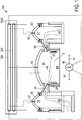
- Fig. 1 shows a simplified representation of a regeneratively heated industrial furnace 100 with a furnace chamber 10, the upper furnace chamber 1 is controlled as a controlled system and in which the lower furnace chamber 2 has a glass melting tank, not shown. Glass contained in the glass melting tank is heated above the furnace chamber 10 above the melting temperature and melted to produce flat glass or the like and treated appropriately.
- the industrial furnace 100 is heated in the present case by fuel 20, in the present case in the form of fuel gas, is injected into the upper furnace 1 via a plurality of laterally mounted fuel injectors 20. Of the fuel injectors 20, a left injector 20 is shown here. Of further fuel injectors 20 ', a right injector 20' is shown in the present case.
- a number of six injectors 20, 20 ' may be provided on the left side and the right side, respectively.
- firing period is injected via a fuel injector 20 fuel gas in the upper furnace 1 practically without combustion air.
- preheated combustion air VB is supplied via a left-side opening 30 to the upper furnace 1.
- the combustion air from the opening 30 mixes in the upper furnace 1 with the fuel gas injected from the fuel injector 20 and leads to the formation of a flame covering the lower furnace 40, which is represented symbolically in the present case.
- FIG. 1 shows the industrial furnace 100 in the state of regenerative firing via the left regenerator 50 and the left injectors 20.
- This and the opening 30 is designed such that the fuel gas supplied via the injectors 20 in sufficient near or stoichiometric range with combustion air of the left regenerator is mixed in the upper furnace 1.
- the in Fig. 1 shown operating state of a left-side firing of the furnace 1 under injection of fuel gas via the left-side injectors 20 and supply of combustion air VB via the left regenerator 50 lasts for a first period of, for example, 20 to 40 min. at.
- combustion air VB is supplied to the upper furnace 1 in the furnace room 10 separately from the fuel gas 20.
- exhaust gas AG is supplied from the upper furnace 1 via right-side openings 30 'to the right regenerator 50' and heats it up.
- a temperature control module 200 of a control device 1000 for the industrial furnace 100 The control of a fuel flow and / or a combustion air flow takes place in principle via a temperature control module 200 of a control device 1000 for the industrial furnace 100.
- a PID controller in the temperature control module 200 can be used, according to which increases a furnace chamber temperature by increasing the fuel flow and / or the combustion air flow or lowering a fuel flow and / or a combustion air flow, a furnace chamber temperature is lowered.
- Temperature values of the regenerator head 51 or 51 'or of the upper furnace chamber 1 are supplied to the temperature control module 200 via suitable temperature probes 52, 52', 53, which in the present case are in some cases also combined with a suitable lambda probe for measuring a fuel-air ratio.
- the temperature measured in the upper furnace via the temperature probe 53 serves as the input of the temperature control module 200, z. B. to make based on a temperature averaging and extrapolation of the temperature behavior to the end of a period.
- the temperature probes 52, 52 ', and here also the temperature probe 53 provide measured temperatures to the input of a symmetry control module 300.
- the temperatures at a regenerator head as measured by the temperature probes 52, 52' can serve as the basis of a claimed simplified determination of a preheat characteristic .
- the optionally arranged at the same place lambda probes or other sensors can be measured values, eg. As about air or exhaust gas quantities, provide for such a simplified determination.
- control device 1000 has a symmetry control module 300, which according to the concept of the invention is designed to influence the heat transfer between the first and second regenerators 50, 50 '. In the present case, this takes place via a heat transfer quantity in the form of a time span ⁇ t, by which the second period duration t extends for the colder one of the first and second regenerators 50, 50 'and / or the second period duration for the hotter one of the first and second regenerators 50, 50' t is shortened or shortened for the colder of the first and second regenerators 50, 50 ', the first period t and / or for the hotter of the first and second regenerators 50, 50', the first period t is extended.
- a suitable one Actuator in the form of a timer 60 is in the present case coupled to the symmetry control module 300 and able to shorten or extend the first and second period t depending on the requirements of the Symmetrieregelmodule 300 - the latter is the period by the period ⁇ .DELTA.t in the left Regenerator 50 and right regenerator 50 'shifting arrows 61 is shown symbolically.
- FIG. 2 schematically illustrates the structure of a first rain loop I for temperature control of a temperature control module 200 and the structure of a second control loop II for a Symmetrieregelung for a symmetry control module 300 concerning the left and right regenerator 50, 50 '.
- the first control loop denoted by I represents the temperature control.
- the second control loop denoted by II represents the symmetry control relating to the left and right regenerators 50, 50 '.
- the upper furnace 1 in the furnace chamber 10 of the furnace 100 serves as part of the controlled system R designated R.
- the controlled system R also includes the left regenerator 50 and the right regenerator 50 'and the locations of the regenerators 50, 50th Provided heat Q Li and Q Re from preheated combustion air VB, which are supplied to the upper furnace 1. In the actual sense it concerns heat flows, which in the Fig. 2 are represented with appropriate symbolism.
- the aim of a furnace temperature control is to determine as anticipated as possible the amount of fuel that ensures the technologically desired furnace temperature - and this with changing loads and variable disturbances.
- a stable, uniform fuel flow without unnecessary fluctuations is another prerequisite for efficient heating. It should therefore not be the task of the temperature controller, the inevitable drop in temperature of the vault during about 35 .. 40 seconds fire-free time of reversal by increased fuel use want to balance - another reason why a simple PID controller can not solve the task.
- the prediction of the temperature at the end of the period which is provided by a model of the temperature profile and the control intervention is enabled even if the temperature has not yet reached the final temperature, but is behind the planned temperature rise or unexpectedly leads him ahead. This is applied accordingly to a weighted average of several furnace temperatures.
- the first control loop I is a furnace chamber temperature T as a controlled variable.
- T furnace chamber temperature
- the temperature sensor 53 serves to accommodate the oven space temperature T.
- the temperature values adapted to an oven temperature from the various temperatures T 1 , T 2 ... T N are averaged in an averaging unit 201 to form a weighted temperature average T x .
- the value of the temperature means T x is supplied to an extrapolation unit 202 which is capable of predicting the actual value of the temperature T IST at the respective end of a fire period of the regenerative heating according to a typical time profile of the representative oven temperature.
- the temperature controller R T is presently formed in the form of a PID controller, which is also a target value of the temperature T SOLL is supplied and determines the need for fuel energy E from the difference.
- a fuel energy E is determined, which is to be supplied to the furnace.
- a fuel quantity B in a fuel unit 203 is determined therefrom.
- the fuel unit 203 adjusts an actuator associated with the temperature controller R T , for example in the form of a fuel throttle for an injector 20, 20 ', to set a fuel flow as the first adjustable control variable for an upper furnace such that a desired target temperature T SOLL is distinguished to the aforementioned actual temperature T IST is achieved.
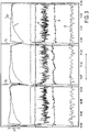
- Fig. 3 In Fig. 3 is in addition to the furnace pressure P, the flap position K for adjusting the combustion air supply to the left and right regenerator 50, 50 'and the oxygen content O of the exhaust gas AG measured and obtained with the temperature sensor 53 temperature average T x compared to that from the prognosis model of the extrapolation 202th emerged temperature signal for the actual temperature T IST is shown. From the forecasting unit 202, the upper and lower peak temperatures are detected at the beginning t B and the end t E of each temperature drop of the temperature T, as shown above.
- a prediction is provided at any time on the period end temperature, which is used as the actual temperature T ACT for the control loop I.
- the period t is designated between the beginning t B and end t E each alternating temperature drop.
- the described temperature drop after a change at the beginning t B and at the end t E of the period t can not be compensated by a temperature controller R T.
- This temperature drop which in Fig. 3 on the contrary would only act as a disturbance of the measured value detection and is logically filtered out of the temperature controller R T to an undesirable reaction of the temperature controller R T to the temperature drop .DELTA.T after changing the firing from the left regenerator 50 to the right regenerator 50 '.
- the predicted temperature T IST at the end of the period is used as the regulator input for the temperature controller R T.
- the temperature controller R T can detect from the period end prediction whether the temperature is rising too fast or too slow and can begin to intervene in the control much earlier.
- a "model" of the physical relationships allows the construction of a symmetry regulation of the regenerators as preconditions for symmetrical furnace temperatures.
- At least the left and right chamber vault temperatures are to be equalized.
- the mathematical model is capable of supplying the corresponding amounts of heat after a one-time basic adaptation and self-learning adjustment, such as real measured values of thermocouples.
- the symmetry controller R S regulates the present in Fig. 4 shown difference ⁇ Q of the amounts of heat to zero.
- the symmetry controller R S for the regenerators 50, 50 ' provides a time interval ⁇ t, with which the period t for the firing of the upper furnace 1 via the regenerators 50, 50' is changed.
- both sides of the fire are operated with the same lambda values and both regenerators are at approximately the same state, the symmetry controller will again find equal period times for left and right fires after the heat equalization between the regenerator sides has been established without operator intervention.
- melted islands 4 are easy to identify. Melting islands have changing spatial coordinates of their centroid in consecutive furnace space images, with the centroid following a trajectory. In contrast, the location coordinates of a centroid in a bubbling spot are at a fixed position. Melting islands have a lower brightness than a foam structure. Contamination on an objective of the furnace chamber camera or other part of the image processing 5 can be identified by the fact that these are immutable in successive image analyzes in terms of position, size and brightness. This means that it is possible to differentiate the melting islands 4 from all other objects on a video image and to determine the area occupied by the melting islands sufficiently precisely where they are in direct contact with bubbling spots or move through the bubbling spots.
- Fig. 5 schematically shows the representation of a first and second control loop as in Fig. 2 in a control device, wherein the first control loop is modified according to the concept of the particularly preferred embodiment of the invention.
- the first controller is designed for a combined controlled variable, wherein the combined controlled variable is determined from a furnace chamber temperature as the first controlled variable and a Schmelzgutbedeckung as a second controlled variable.
- the furnace chamber of the industrial furnace 100 with the upper furnace space 1 and the lower furnace space 2 is shown, wherein in a glass melting tank of the lower furnace space 2, the melt 3 is shown with individual melting islands 4.
- An image processing 5 provides, inter alia, the furnace chamber camera 5.1 and an object recognition device connected thereto for a furnace chamber image, here video image, of the furnace chamber camera 5.1.
- the object recognition 5.2 uses known methods of digital filtering of a furnace chamber image 5.3 to distinguish fundamentally different objects on the basis of their appearance - such as brightness, shape and size - and movement.
- typical objects of the furnace chamber image in particular the above-mentioned objects and the actual melting islands 4 from not yet liquefied melt are recognized. These can be distinguished from the other objects, recognize and clearly identify.
- the modified controller R mod has a combined controlled variable R TG whose control deviation D is determined from a control deviation dT of a furnace chamber temperature T SOLL - T IST and a control deviation dG of a surface coverage G SOLL - G IST .
- a regulation of the furnace heating which only on the massecup alone or only on the Temperature control alone turns off, would lead to unacceptable temperature fluctuations in the furnace chamber.
- the combined heater for the oven heating in approach the temperature controller R T described above, the output of which continues to represent the fuel energy to be supplied to the furnace.
- a weighted average of control deviations SUM i (dT i ) can be set, which can take into account the abovementioned temperature values adapted to an oven temperature from the various temperatures T 1 , T 2 ... T N.
- the influence of an area coverage of further objects can also be analytically taken into account by a weighted average of control deviations SUM j (dG j ).
- FIG. 6 an example of a geometrically oriented unprocessed furnace chamber image 5.3, as it was recorded by a furnace chamber camera 5.2 as a video image.
- a similar oven space image 5.3 is shown as taken by a furnace room camera 5.2 as a video image processed by object recognition 5.2; as a result, bubbling spots O1 are indicated.
- the spatial coordinates of their centroid in successive video images do not change.
- a similar oven space image 5.3 is shown as taken by a furnace room camera 5.2 as a video image processed by object recognition 5.2;
- a whole series of objects O - including the relevant melting islands 4 - are colored and due to their appearance (in particular brightness, shape and size), position and Distinguished trajectory.
- the spatial coordinates of a centroid of the melting islands 4 in successive video images change and follow a trajectory.
- Dirt on the lens of the camera chamber camera 5.1 can be identified by the fact that they are immutable in successive image analysis in position, size and brightness.
- Fig. 9 is a similar furnace space image 5.3 as taken by a furnace room camera 5.2 as a video image processed by object recognition 5.2;
- foam structures O2 are distinguished from the melted product islands 4 which have not yet been melted. Melting islands 4 differ from foam structures O2 due to their lower brightness. Only the area occupied by the melting islands 4 is used to determine the melt coverage.
Landscapes
- Engineering & Computer Science (AREA)
- Chemical & Material Sciences (AREA)
- Materials Engineering (AREA)
- Organic Chemistry (AREA)
- Remote Sensing (AREA)
- Physics & Mathematics (AREA)
- General Physics & Mathematics (AREA)
- Automation & Control Theory (AREA)
- Waste-Gas Treatment And Other Accessory Devices For Furnaces (AREA)
- Regulation And Control Of Combustion (AREA)
Priority Applications (1)
| Application Number | Priority Date | Filing Date | Title |
|---|---|---|---|
| PL11767207T PL2619151T3 (pl) | 2010-09-21 | 2011-09-21 | Sposób regulowanej pracy nagrzewanego regeneracyjnie pieca przemysłowego, urządzenie sterujące i piec przemysłowy z urządzeniem sterującym |
Applications Claiming Priority (2)
| Application Number | Priority Date | Filing Date | Title |
|---|---|---|---|
| DE102010041155.8A DE102010041155B4 (de) | 2010-09-21 | 2010-09-21 | Verfahren zum geregelten Betrieb eines regenerativ beheizten Industrieofens, Steuereinrichtung und Industrieofen |
| PCT/EP2011/066463 WO2012038488A1 (de) | 2010-09-21 | 2011-09-21 | Verfahren zum geregelten betrieb eines regenerativ beheizten industrieofens, steuereinrichtung und industrieofen |
Publications (2)
| Publication Number | Publication Date |
|---|---|
| EP2619151A1 EP2619151A1 (de) | 2013-07-31 |
| EP2619151B1 true EP2619151B1 (de) | 2018-02-14 |
Family
ID=44773054
Family Applications (1)
| Application Number | Title | Priority Date | Filing Date |
|---|---|---|---|
| EP11767207.1A Active EP2619151B1 (de) | 2010-09-21 | 2011-09-21 | Verfahren zum geregelten betrieb eines regenerativ beheizten industrieofens, steuereinrichtung und industrieofen mit steuereinrichtung |
Country Status (6)
| Country | Link |
|---|---|
| EP (1) | EP2619151B1 (pl) |
| CN (1) | CN103221349A (pl) |
| DE (1) | DE102010041155B4 (pl) |
| PL (1) | PL2619151T3 (pl) |
| PT (1) | PT2619151T (pl) |
| WO (1) | WO2012038488A1 (pl) |
Families Citing this family (7)
| Publication number | Priority date | Publication date | Assignee | Title |
|---|---|---|---|---|
| DE102012210753A1 (de) * | 2012-06-25 | 2014-01-02 | Software & Technologie Glas Gmbh (Stg) | Verfahren zur Bestimmung eines Kohlenmonoxid-Anteils in einem Abgasstrom, insbesondere eine Steuereinrichtung und einem regenerativ befeuerten Industrieofen |
| CN104478196B (zh) * | 2014-12-26 | 2017-02-22 | 秦皇岛玻璃工业研究设计院 | 一种用于玻璃窑炉换向燃烧的燃烧器及其加工方法 |
| US10548564B2 (en) | 2015-02-26 | 2020-02-04 | Rivanna Medical, LLC | System and method for ultrasound imaging of regions containing bone structure |
| DE102015203978A1 (de) * | 2015-03-05 | 2016-09-08 | Stg Combustion Control Gmbh & Co. Kg | Verfahren zum geregelten Betrieb eines, insbesondere regenerativ, beheizten Industrieofens, Steuer- und Regeleinrichtung und beheizbarer Industrieofen |
| DE102019129192A1 (de) | 2019-10-29 | 2021-04-29 | Software & Technologie Glas Gmbh (Stg) | Verfahren zum geregelten Betrieb eines regenerativ beheizten Industrieofens, Steuereinrichtung und Industrieofen |
| CN113941213B (zh) * | 2020-07-15 | 2023-09-29 | 中冶长天国际工程有限责任公司 | 解析塔热风量控制方法、系统及装置 |
| CN120846100B (zh) * | 2025-09-22 | 2025-12-09 | 西安成航炉业有限公司 | 一种适用于高温加热炉的温度连续控制方法 |
Family Cites Families (12)
| Publication number | Priority date | Publication date | Assignee | Title |
|---|---|---|---|---|
| US2069542A (en) * | 1935-02-23 | 1937-02-02 | Owens Illinois Glass Co | Furnace |
| US3028095A (en) * | 1958-04-29 | 1962-04-03 | Bailey Meter Co | Temperature control of a process having high heat storage capacity |
| FR1260888A (fr) * | 1960-06-02 | 1961-05-12 | Siemens Ag | Dispositif pour inverser automatiquement les chambres de récupération des fours àrégénération |
| GB1188256A (en) * | 1968-06-13 | 1970-04-15 | Owens Corning Fiberglass Corp | Furnace Control Apparatus |
| SU620433A1 (ru) * | 1977-03-23 | 1978-08-25 | Киевский Ордена Ленина Политехнический Институт Им.50-Летия Великой Октябрьской Социалистической Революции | Способ автоматического управлени регенеративной стекловаренной печью |
| SU743965A1 (ru) * | 1978-04-19 | 1980-06-30 | Государственный научно-исследовательский институт стекла | Способ автоматического управлени регенеративной стекловаренной печью |
| DD143158A1 (de) * | 1979-06-05 | 1980-08-06 | Wolfgang Heller | Verfahren zur regulierung der temperatur einer glasschmelzwanne |
| US4409012A (en) * | 1982-02-16 | 1983-10-11 | Owens-Illinois, Inc. | Method and apparatus for monitoring a glass furnace |
| DD204533A1 (de) * | 1982-03-15 | 1983-11-30 | Werner Goetze | Verfahren zum einstellen guenstiger luft-brennstoff-verhaeltnisse an industrieoefen mit regeneratoren |
| DE3610365A1 (de) | 1985-11-06 | 1987-05-14 | Cottbus Energiekombinat | Verfahren zur aktuell technologisch gefuehrten regelung der oberofenbeheizung von glasschmelzwannen |
| SU1481214A1 (ru) * | 1987-01-06 | 1989-05-23 | Гусевский Филиал Государственного Научно-Исследовательского Института Стекла | Способ управлени стекловаренной регенеративной печью |
| ATE354546T1 (de) | 2000-12-14 | 2007-03-15 | Software & Tech Glas Gmbh | Verfahren zur messung und regelung qualitätsbestimmender parameter der rauhschmelze von glasschmelzwannen |
-
2010
- 2010-09-21 DE DE102010041155.8A patent/DE102010041155B4/de not_active Expired - Fee Related
-
2011
- 2011-09-21 EP EP11767207.1A patent/EP2619151B1/de active Active
- 2011-09-21 PT PT117672071T patent/PT2619151T/pt unknown
- 2011-09-21 WO PCT/EP2011/066463 patent/WO2012038488A1/de not_active Ceased
- 2011-09-21 PL PL11767207T patent/PL2619151T3/pl unknown
- 2011-09-21 CN CN2011800559960A patent/CN103221349A/zh active Pending
Also Published As
| Publication number | Publication date |
|---|---|
| EP2619151A1 (de) | 2013-07-31 |
| WO2012038488A1 (de) | 2012-03-29 |
| DE102010041155A1 (de) | 2012-03-22 |
| PT2619151T (pt) | 2018-04-10 |
| CN103221349A (zh) | 2013-07-24 |
| DE102010041155B4 (de) | 2016-01-28 |
| PL2619151T3 (pl) | 2018-08-31 |
Similar Documents
| Publication | Publication Date | Title |
|---|---|---|
| EP2619150B1 (de) | Verfahren zum geregelten betrieb eines regenerativ beheizten industrieofens, steuereinrichtung und industrieofen | |
| WO2012038488A1 (de) | Verfahren zum geregelten betrieb eines regenerativ beheizten industrieofens, steuereinrichtung und industrieofen | |
| DE60108293T2 (de) | Regelung von Sauerstoffbrennern in Öfen | |
| DE69910702T2 (de) | Vorrichtung zum Regeln der Schmelzung und/oder Entgasung von Glasschmelzofen | |
| EP3265431B1 (de) | Verfahren zum geregelten betrieb eines, insbesondere regenerativ, beheizten industrieofens, steuer- und regeleinrichtung und beheizbarer industrieofen | |
| DE2507840B2 (de) | Regelverfahren für die Zementherstellung im Drehrohrofen und Regelvorrichtung | |
| DE2054964A1 (de) | Steuersystem fur einen Hochofen Winderhitzer | |
| DE2335810A1 (de) | Elektrischer ofen zur erhitzung eines fliessfaehigen materials, vorzugsweise glas | |
| DE69907437T2 (de) | Steuerungsverfahren und vorrichtung für einen ringkammerofen | |
| EP1458649B1 (de) | Verfahren zur messung und regelung qualitätsbestimmender parameter der rauhschmelze von glasschmelzwannen | |
| DE2047529A1 (de) | Verfahren und Vorrichtung zur Re gelung eines Zement Drehrohrofens | |
| DE19521513C2 (de) | Verfahren zur Regelung der Beheizung von Glas-Wannenöfen | |
| EP2976586A2 (de) | Verfahren zum geregelten betrieb eines regenerativ beheizten industrieofens, steuereinheit und industrieofen | |
| EP2851347A1 (de) | Verfahren zur Betriebsoptimierung einer als regenerative U-Flammenwanne mit zwei Feuerungsseiten ausgebildeten Glasschmelzwanne zur Glasherstellung mit Gasbrennern zur Temperierung eines in der Glasschmelzwanne befindlichen Glasbades sowie zugehörige Brenner | |
| EP4051648A1 (de) | Verfahren zum geregelten betrieb eines regenerativ beheizten industrieofens, steuereinrichtung und industrieofen | |
| DE102009002336A1 (de) | Verfahren und Vorrichtung zum Läutern einer Glasschmelze | |
| DE4422376A1 (de) | Verfahren zum Steuern der Temperatur von Glas in einem Speiservorherd | |
| DE4410971B4 (de) | Verfahren zur Regelung der Temperatur in einem Heizofen | |
| DE1596578B2 (de) | Vorrichtung zum laeutern einer glasschmelze und zum anschlies senden abziehen von glasfaeden | |
| EP1543283A1 (de) | Optimierung der pechdampfverbrennung in einem brennofen für kohlenstoffelektroden | |
| DE10160824A1 (de) | Regelungsverfahren für den Hauptrezirkulationsstrom des Glases in Wannenöfen | |
| DE102022206100A1 (de) | Schachtofen für die Erschmelzung von Kupfer und Verfahren hierzu | |
| DE2747832C3 (de) | Herstellungsverfahren für Flachglas | |
| DE1596578C (de) | Vorrichtung zum Läutern einer Glasschmelze und zum anschließenden Abziehen von Glasfäden. Ausscheidung aus: 1421756 | |
| DD275041A1 (de) | Verfahren und anordnung zur regelung des schmelzprozesses in vollelektrisch beheizten glasschmelzwannen |
Legal Events
| Date | Code | Title | Description |
|---|---|---|---|
| PUAI | Public reference made under article 153(3) epc to a published international application that has entered the european phase |
Free format text: ORIGINAL CODE: 0009012 |
|
| 17P | Request for examination filed |
Effective date: 20130422 |
|
| AK | Designated contracting states |
Kind code of ref document: A1 Designated state(s): AL AT BE BG CH CY CZ DE DK EE ES FI FR GB GR HR HU IE IS IT LI LT LU LV MC MK MT NL NO PL PT RO RS SE SI SK SM TR |
|
| DAX | Request for extension of the european patent (deleted) | ||
| 17Q | First examination report despatched |
Effective date: 20140221 |
|
| GRAP | Despatch of communication of intention to grant a patent |
Free format text: ORIGINAL CODE: EPIDOSNIGR1 |
|
| INTG | Intention to grant announced |
Effective date: 20170504 |
|
| GRAS | Grant fee paid |
Free format text: ORIGINAL CODE: EPIDOSNIGR3 |
|
| GRAJ | Information related to disapproval of communication of intention to grant by the applicant or resumption of examination proceedings by the epo deleted |
Free format text: ORIGINAL CODE: EPIDOSDIGR1 |
|
| GRAL | Information related to payment of fee for publishing/printing deleted |
Free format text: ORIGINAL CODE: EPIDOSDIGR3 |
|
| GRAP | Despatch of communication of intention to grant a patent |
Free format text: ORIGINAL CODE: EPIDOSNIGR1 |
|
| INTC | Intention to grant announced (deleted) | ||
| INTG | Intention to grant announced |
Effective date: 20171019 |
|
| GRAA | (expected) grant |
Free format text: ORIGINAL CODE: 0009210 |
|
| AK | Designated contracting states |
Kind code of ref document: B1 Designated state(s): AL AT BE BG CH CY CZ DE DK EE ES FI FR GB GR HR HU IE IS IT LI LT LU LV MC MK MT NL NO PL PT RO RS SE SI SK SM TR |
|
| REG | Reference to a national code |
Ref country code: GB Ref legal event code: FG4D Free format text: NOT ENGLISH |
|
| REG | Reference to a national code |
Ref country code: CH Ref legal event code: EP |
|
| REG | Reference to a national code |
Ref country code: IE Ref legal event code: FG4D Free format text: LANGUAGE OF EP DOCUMENT: GERMAN |
|
| REG | Reference to a national code |
Ref country code: DE Ref legal event code: R096 Ref document number: 502011013728 Country of ref document: DE Ref country code: AT Ref legal event code: REF Ref document number: 969725 Country of ref document: AT Kind code of ref document: T Effective date: 20180315 |
|
| REG | Reference to a national code |
Ref country code: PT Ref legal event code: SC4A Ref document number: 2619151 Country of ref document: PT Date of ref document: 20180410 Kind code of ref document: T Free format text: AVAILABILITY OF NATIONAL TRANSLATION Effective date: 20180404 |
|
| REG | Reference to a national code |
Ref country code: NL Ref legal event code: FP |
|
| PG25 | Lapsed in a contracting state [announced via postgrant information from national office to epo] |
Ref country code: NO Free format text: LAPSE BECAUSE OF FAILURE TO SUBMIT A TRANSLATION OF THE DESCRIPTION OR TO PAY THE FEE WITHIN THE PRESCRIBED TIME-LIMIT Effective date: 20180514 Ref country code: LT Free format text: LAPSE BECAUSE OF FAILURE TO SUBMIT A TRANSLATION OF THE DESCRIPTION OR TO PAY THE FEE WITHIN THE PRESCRIBED TIME-LIMIT Effective date: 20180214 Ref country code: FI Free format text: LAPSE BECAUSE OF FAILURE TO SUBMIT A TRANSLATION OF THE DESCRIPTION OR TO PAY THE FEE WITHIN THE PRESCRIBED TIME-LIMIT Effective date: 20180214 Ref country code: HR Free format text: LAPSE BECAUSE OF FAILURE TO SUBMIT A TRANSLATION OF THE DESCRIPTION OR TO PAY THE FEE WITHIN THE PRESCRIBED TIME-LIMIT Effective date: 20180214 Ref country code: ES Free format text: LAPSE BECAUSE OF FAILURE TO SUBMIT A TRANSLATION OF THE DESCRIPTION OR TO PAY THE FEE WITHIN THE PRESCRIBED TIME-LIMIT Effective date: 20180214 Ref country code: CY Free format text: LAPSE BECAUSE OF FAILURE TO SUBMIT A TRANSLATION OF THE DESCRIPTION OR TO PAY THE FEE WITHIN THE PRESCRIBED TIME-LIMIT Effective date: 20180214 |
|
| PG25 | Lapsed in a contracting state [announced via postgrant information from national office to epo] |
Ref country code: RS Free format text: LAPSE BECAUSE OF FAILURE TO SUBMIT A TRANSLATION OF THE DESCRIPTION OR TO PAY THE FEE WITHIN THE PRESCRIBED TIME-LIMIT Effective date: 20180214 Ref country code: LV Free format text: LAPSE BECAUSE OF FAILURE TO SUBMIT A TRANSLATION OF THE DESCRIPTION OR TO PAY THE FEE WITHIN THE PRESCRIBED TIME-LIMIT Effective date: 20180214 Ref country code: SE Free format text: LAPSE BECAUSE OF FAILURE TO SUBMIT A TRANSLATION OF THE DESCRIPTION OR TO PAY THE FEE WITHIN THE PRESCRIBED TIME-LIMIT Effective date: 20180214 Ref country code: GR Free format text: LAPSE BECAUSE OF FAILURE TO SUBMIT A TRANSLATION OF THE DESCRIPTION OR TO PAY THE FEE WITHIN THE PRESCRIBED TIME-LIMIT Effective date: 20180515 Ref country code: BG Free format text: LAPSE BECAUSE OF FAILURE TO SUBMIT A TRANSLATION OF THE DESCRIPTION OR TO PAY THE FEE WITHIN THE PRESCRIBED TIME-LIMIT Effective date: 20180514 |
|
| REG | Reference to a national code |
Ref country code: FR Ref legal event code: PLFP Year of fee payment: 8 |
|
| PG25 | Lapsed in a contracting state [announced via postgrant information from national office to epo] |
Ref country code: MT Free format text: LAPSE BECAUSE OF FAILURE TO SUBMIT A TRANSLATION OF THE DESCRIPTION OR TO PAY THE FEE WITHIN THE PRESCRIBED TIME-LIMIT Effective date: 20180214 |
|
| PG25 | Lapsed in a contracting state [announced via postgrant information from national office to epo] |
Ref country code: EE Free format text: LAPSE BECAUSE OF FAILURE TO SUBMIT A TRANSLATION OF THE DESCRIPTION OR TO PAY THE FEE WITHIN THE PRESCRIBED TIME-LIMIT Effective date: 20180214 Ref country code: AL Free format text: LAPSE BECAUSE OF FAILURE TO SUBMIT A TRANSLATION OF THE DESCRIPTION OR TO PAY THE FEE WITHIN THE PRESCRIBED TIME-LIMIT Effective date: 20180214 Ref country code: RO Free format text: LAPSE BECAUSE OF FAILURE TO SUBMIT A TRANSLATION OF THE DESCRIPTION OR TO PAY THE FEE WITHIN THE PRESCRIBED TIME-LIMIT Effective date: 20180214 |
|
| REG | Reference to a national code |
Ref country code: DE Ref legal event code: R097 Ref document number: 502011013728 Country of ref document: DE |
|
| PG25 | Lapsed in a contracting state [announced via postgrant information from national office to epo] |
Ref country code: SK Free format text: LAPSE BECAUSE OF FAILURE TO SUBMIT A TRANSLATION OF THE DESCRIPTION OR TO PAY THE FEE WITHIN THE PRESCRIBED TIME-LIMIT Effective date: 20180214 Ref country code: DK Free format text: LAPSE BECAUSE OF FAILURE TO SUBMIT A TRANSLATION OF THE DESCRIPTION OR TO PAY THE FEE WITHIN THE PRESCRIBED TIME-LIMIT Effective date: 20180214 Ref country code: SM Free format text: LAPSE BECAUSE OF FAILURE TO SUBMIT A TRANSLATION OF THE DESCRIPTION OR TO PAY THE FEE WITHIN THE PRESCRIBED TIME-LIMIT Effective date: 20180214 |
|
| PGFP | Annual fee paid to national office [announced via postgrant information from national office to epo] |
Ref country code: PL Payment date: 20180913 Year of fee payment: 8 Ref country code: TR Payment date: 20180917 Year of fee payment: 8 |
|
| PLBE | No opposition filed within time limit |
Free format text: ORIGINAL CODE: 0009261 |
|
| STAA | Information on the status of an ep patent application or granted ep patent |
Free format text: STATUS: NO OPPOSITION FILED WITHIN TIME LIMIT |
|
| PGFP | Annual fee paid to national office [announced via postgrant information from national office to epo] |
Ref country code: PT Payment date: 20180921 Year of fee payment: 8 |
|
| 26N | No opposition filed |
Effective date: 20181115 |
|
| PG25 | Lapsed in a contracting state [announced via postgrant information from national office to epo] |
Ref country code: SI Free format text: LAPSE BECAUSE OF FAILURE TO SUBMIT A TRANSLATION OF THE DESCRIPTION OR TO PAY THE FEE WITHIN THE PRESCRIBED TIME-LIMIT Effective date: 20180214 |
|
| PG25 | Lapsed in a contracting state [announced via postgrant information from national office to epo] |
Ref country code: MC Free format text: LAPSE BECAUSE OF FAILURE TO SUBMIT A TRANSLATION OF THE DESCRIPTION OR TO PAY THE FEE WITHIN THE PRESCRIBED TIME-LIMIT Effective date: 20180214 |
|
| REG | Reference to a national code |
Ref country code: CH Ref legal event code: PL |
|
| REG | Reference to a national code |
Ref country code: IE Ref legal event code: MM4A |
|
| PG25 | Lapsed in a contracting state [announced via postgrant information from national office to epo] |
Ref country code: IT Free format text: LAPSE BECAUSE OF NON-PAYMENT OF DUE FEES Effective date: 20180921 Ref country code: IE Free format text: LAPSE BECAUSE OF NON-PAYMENT OF DUE FEES Effective date: 20180921 |
|
| PG25 | Lapsed in a contracting state [announced via postgrant information from national office to epo] |
Ref country code: CH Free format text: LAPSE BECAUSE OF NON-PAYMENT OF DUE FEES Effective date: 20180930 Ref country code: LI Free format text: LAPSE BECAUSE OF NON-PAYMENT OF DUE FEES Effective date: 20180930 |
|
| PGFP | Annual fee paid to national office [announced via postgrant information from national office to epo] |
Ref country code: FR Payment date: 20190926 Year of fee payment: 9 Ref country code: LU Payment date: 20190923 Year of fee payment: 9 Ref country code: NL Payment date: 20190923 Year of fee payment: 9 |
|
| REG | Reference to a national code |
Ref country code: AT Ref legal event code: MM01 Ref document number: 969725 Country of ref document: AT Kind code of ref document: T Effective date: 20180921 |
|
| PG25 | Lapsed in a contracting state [announced via postgrant information from national office to epo] |
Ref country code: AT Free format text: LAPSE BECAUSE OF NON-PAYMENT OF DUE FEES Effective date: 20180921 |
|
| PGFP | Annual fee paid to national office [announced via postgrant information from national office to epo] |
Ref country code: GB Payment date: 20191031 Year of fee payment: 9 |
|
| PG25 | Lapsed in a contracting state [announced via postgrant information from national office to epo] |
Ref country code: HU Free format text: LAPSE BECAUSE OF FAILURE TO SUBMIT A TRANSLATION OF THE DESCRIPTION OR TO PAY THE FEE WITHIN THE PRESCRIBED TIME-LIMIT; INVALID AB INITIO Effective date: 20110921 |
|
| PG25 | Lapsed in a contracting state [announced via postgrant information from national office to epo] |
Ref country code: MK Free format text: LAPSE BECAUSE OF NON-PAYMENT OF DUE FEES Effective date: 20180214 |
|
| PG25 | Lapsed in a contracting state [announced via postgrant information from national office to epo] |
Ref country code: PT Free format text: LAPSE BECAUSE OF NON-PAYMENT OF DUE FEES Effective date: 20200424 Ref country code: IS Free format text: LAPSE BECAUSE OF FAILURE TO SUBMIT A TRANSLATION OF THE DESCRIPTION OR TO PAY THE FEE WITHIN THE PRESCRIBED TIME-LIMIT Effective date: 20180614 |
|
| REG | Reference to a national code |
Ref country code: NL Ref legal event code: MM Effective date: 20201001 |
|
| GBPC | Gb: european patent ceased through non-payment of renewal fee |
Effective date: 20200921 |
|
| PG25 | Lapsed in a contracting state [announced via postgrant information from national office to epo] |
Ref country code: LU Free format text: LAPSE BECAUSE OF NON-PAYMENT OF DUE FEES Effective date: 20200921 Ref country code: NL Free format text: LAPSE BECAUSE OF NON-PAYMENT OF DUE FEES Effective date: 20201001 |
|
| PG25 | Lapsed in a contracting state [announced via postgrant information from national office to epo] |
Ref country code: FR Free format text: LAPSE BECAUSE OF NON-PAYMENT OF DUE FEES Effective date: 20200930 |
|
| PG25 | Lapsed in a contracting state [announced via postgrant information from national office to epo] |
Ref country code: GB Free format text: LAPSE BECAUSE OF NON-PAYMENT OF DUE FEES Effective date: 20200921 |
|
| PGFP | Annual fee paid to national office [announced via postgrant information from national office to epo] |
Ref country code: BE Payment date: 20210921 Year of fee payment: 11 |
|
| PG25 | Lapsed in a contracting state [announced via postgrant information from national office to epo] |
Ref country code: PL Free format text: LAPSE BECAUSE OF NON-PAYMENT OF DUE FEES Effective date: 20190921 |
|
| PG25 | Lapsed in a contracting state [announced via postgrant information from national office to epo] |
Ref country code: TR Free format text: LAPSE BECAUSE OF NON-PAYMENT OF DUE FEES Effective date: 20190921 |
|
| REG | Reference to a national code |
Ref country code: BE Ref legal event code: MM Effective date: 20220930 |
|
| PG25 | Lapsed in a contracting state [announced via postgrant information from national office to epo] |
Ref country code: BE Free format text: LAPSE BECAUSE OF NON-PAYMENT OF DUE FEES Effective date: 20220930 |
|
| PGFP | Annual fee paid to national office [announced via postgrant information from national office to epo] |
Ref country code: CZ Payment date: 20240910 Year of fee payment: 14 |
|
| PGFP | Annual fee paid to national office [announced via postgrant information from national office to epo] |
Ref country code: DE Payment date: 20251007 Year of fee payment: 15 |
|
| REG | Reference to a national code |
Ref country code: DE Ref legal event code: R082 Ref document number: 502011013728 Country of ref document: DE Representative=s name: EISENFUEHR SPEISER PATENTANWAELTE RECHTSANWAEL, DE |
|
| PG25 | Lapsed in a contracting state [announced via postgrant information from national office to epo] |
Ref country code: CZ Free format text: LAPSE BECAUSE OF NON-PAYMENT OF DUE FEES Effective date: 20250921 |