EP2618032A2 - Joint d'étanchéité d'arbre, notamment joint d'arbre radial - Google Patents
Joint d'étanchéité d'arbre, notamment joint d'arbre radial Download PDFInfo
- Publication number
- EP2618032A2 EP2618032A2 EP13000228.0A EP13000228A EP2618032A2 EP 2618032 A2 EP2618032 A2 EP 2618032A2 EP 13000228 A EP13000228 A EP 13000228A EP 2618032 A2 EP2618032 A2 EP 2618032A2
- Authority
- EP
- European Patent Office
- Prior art keywords
- shaft seal
- sealing
- seal according
- sealing lip
- shaft
- Prior art date
- Legal status (The legal status is an assumption and is not a legal conclusion. Google has not performed a legal analysis and makes no representation as to the accuracy of the status listed.)
- Granted
Links
- 238000007789 sealing Methods 0.000 claims abstract description 165
- 239000000806 elastomer Substances 0.000 claims abstract description 53
- 229920001971 elastomer Polymers 0.000 claims abstract description 53
- -1 polytetrafluoroethylene Polymers 0.000 claims abstract description 6
- 229920001343 polytetrafluoroethylene Polymers 0.000 claims abstract description 6
- 239000004810 polytetrafluoroethylene Substances 0.000 claims abstract description 6
- 230000001419 dependent effect Effects 0.000 claims description 5
- 230000007704 transition Effects 0.000 claims description 3
- 238000009826 distribution Methods 0.000 description 9
- 239000000463 material Substances 0.000 description 5
- 230000000694 effects Effects 0.000 description 4
- 238000005461 lubrication Methods 0.000 description 4
- 238000004519 manufacturing process Methods 0.000 description 4
- PEDCQBHIVMGVHV-UHFFFAOYSA-N Glycerine Chemical compound OCC(O)CO PEDCQBHIVMGVHV-UHFFFAOYSA-N 0.000 description 3
- 230000004323 axial length Effects 0.000 description 3
- 238000009434 installation Methods 0.000 description 3
- 239000007769 metal material Substances 0.000 description 3
- 230000000284 resting effect Effects 0.000 description 3
- 230000003068 static effect Effects 0.000 description 3
- 108091006625 SLC10A6 Proteins 0.000 description 2
- 102100021993 Sterol O-acyltransferase 1 Human genes 0.000 description 2
- 239000002826 coolant Substances 0.000 description 2
- 238000013016 damping Methods 0.000 description 2
- 230000007423 decrease Effects 0.000 description 2
- 239000004033 plastic Substances 0.000 description 2
- 229910000906 Bronze Inorganic materials 0.000 description 1
- 229920000049 Carbon (fiber) Polymers 0.000 description 1
- 101710148753 Ornithine aminotransferase Proteins 0.000 description 1
- 102100027177 Ornithine aminotransferase, mitochondrial Human genes 0.000 description 1
- 239000000654 additive Substances 0.000 description 1
- 230000005540 biological transmission Effects 0.000 description 1
- 230000015572 biosynthetic process Effects 0.000 description 1
- 239000010974 bronze Substances 0.000 description 1
- 239000004917 carbon fiber Substances 0.000 description 1
- 238000011109 contamination Methods 0.000 description 1
- KUNSUQLRTQLHQQ-UHFFFAOYSA-N copper tin Chemical compound [Cu].[Sn] KUNSUQLRTQLHQQ-UHFFFAOYSA-N 0.000 description 1
- 239000013536 elastomeric material Substances 0.000 description 1
- 239000000945 filler Substances 0.000 description 1
- 239000003365 glass fiber Substances 0.000 description 1
- 230000003993 interaction Effects 0.000 description 1
- 239000000314 lubricant Substances 0.000 description 1
- 230000001050 lubricating effect Effects 0.000 description 1
- 230000013011 mating Effects 0.000 description 1
- 238000003825 pressing Methods 0.000 description 1
- 230000003134 recirculating effect Effects 0.000 description 1
- 230000000717 retained effect Effects 0.000 description 1
- 239000000565 sealant Substances 0.000 description 1
- 239000000126 substance Substances 0.000 description 1
- XLYOFNOQVPJJNP-UHFFFAOYSA-N water Substances O XLYOFNOQVPJJNP-UHFFFAOYSA-N 0.000 description 1
Images


Classifications
-
- F—MECHANICAL ENGINEERING; LIGHTING; HEATING; WEAPONS; BLASTING
- F16—ENGINEERING ELEMENTS AND UNITS; GENERAL MEASURES FOR PRODUCING AND MAINTAINING EFFECTIVE FUNCTIONING OF MACHINES OR INSTALLATIONS; THERMAL INSULATION IN GENERAL
- F16J—PISTONS; CYLINDERS; SEALINGS
- F16J15/00—Sealings
- F16J15/16—Sealings between relatively-moving surfaces
- F16J15/32—Sealings between relatively-moving surfaces with elastic sealings, e.g. O-rings
- F16J15/3204—Sealings between relatively-moving surfaces with elastic sealings, e.g. O-rings with at least one lip
- F16J15/3208—Sealings between relatively-moving surfaces with elastic sealings, e.g. O-rings with at least one lip provided with tension elements, e.g. elastic rings
-
- F—MECHANICAL ENGINEERING; LIGHTING; HEATING; WEAPONS; BLASTING
- F16—ENGINEERING ELEMENTS AND UNITS; GENERAL MEASURES FOR PRODUCING AND MAINTAINING EFFECTIVE FUNCTIONING OF MACHINES OR INSTALLATIONS; THERMAL INSULATION IN GENERAL
- F16J—PISTONS; CYLINDERS; SEALINGS
- F16J15/00—Sealings
- F16J15/16—Sealings between relatively-moving surfaces
- F16J15/32—Sealings between relatively-moving surfaces with elastic sealings, e.g. O-rings
- F16J15/3204—Sealings between relatively-moving surfaces with elastic sealings, e.g. O-rings with at least one lip
- F16J15/3228—Sealings between relatively-moving surfaces with elastic sealings, e.g. O-rings with at least one lip formed by deforming a flat ring
-
- F—MECHANICAL ENGINEERING; LIGHTING; HEATING; WEAPONS; BLASTING
- F16—ENGINEERING ELEMENTS AND UNITS; GENERAL MEASURES FOR PRODUCING AND MAINTAINING EFFECTIVE FUNCTIONING OF MACHINES OR INSTALLATIONS; THERMAL INSULATION IN GENERAL
- F16J—PISTONS; CYLINDERS; SEALINGS
- F16J15/00—Sealings
- F16J15/16—Sealings between relatively-moving surfaces
- F16J15/32—Sealings between relatively-moving surfaces with elastic sealings, e.g. O-rings
- F16J15/3204—Sealings between relatively-moving surfaces with elastic sealings, e.g. O-rings with at least one lip
- F16J15/3232—Sealings between relatively-moving surfaces with elastic sealings, e.g. O-rings with at least one lip having two or more lips
-
- F—MECHANICAL ENGINEERING; LIGHTING; HEATING; WEAPONS; BLASTING
- F16—ENGINEERING ELEMENTS AND UNITS; GENERAL MEASURES FOR PRODUCING AND MAINTAINING EFFECTIVE FUNCTIONING OF MACHINES OR INSTALLATIONS; THERMAL INSULATION IN GENERAL
- F16J—PISTONS; CYLINDERS; SEALINGS
- F16J15/00—Sealings
- F16J15/16—Sealings between relatively-moving surfaces
- F16J15/32—Sealings between relatively-moving surfaces with elastic sealings, e.g. O-rings
- F16J15/324—Arrangements for lubrication or cooling of the sealing itself
-
- F—MECHANICAL ENGINEERING; LIGHTING; HEATING; WEAPONS; BLASTING
- F16—ENGINEERING ELEMENTS AND UNITS; GENERAL MEASURES FOR PRODUCING AND MAINTAINING EFFECTIVE FUNCTIONING OF MACHINES OR INSTALLATIONS; THERMAL INSULATION IN GENERAL
- F16J—PISTONS; CYLINDERS; SEALINGS
- F16J15/00—Sealings
- F16J15/16—Sealings between relatively-moving surfaces
- F16J15/32—Sealings between relatively-moving surfaces with elastic sealings, e.g. O-rings
- F16J15/3244—Sealings between relatively-moving surfaces with elastic sealings, e.g. O-rings with hydrodynamic pumping action
Definitions
- the invention relates to a shaft seal, in particular a radial shaft seal, according to the preamble of claim 1.
- sealing elements in the form of radial shaft seals are used as a material for the sealing elements polyfluorocarbon, especially polytetrafluoroethylene, because of their special physical and chemical properties.
- These sealing elements are designed as annular discs whose radially inner region is bent elastically to form the sealing lip.
- polyfluorocarbons especially in polytetrafluoroethylene
- creep is observed.
- these materials have a relatively low mechanical strength. The creep of this material causes the sealing effect to diminish.
- the radial bias which acts on the sealing lip, is increased. However, this leads to a correspondingly greater wear of the sealing lip. For sealing applications it is therefore difficult to find a balance between tightness and wear.
- the invention has the object of providing the generic shaft seal in such a way that their tightness is maintained during structurally simple and cost-effective production during their service life substantially.
- the sealing lip of the sealing element is loaded by the elastomer element in the direction of the component to be sealed. This ensures that the sealing lip always rests with sufficient force on the surface to be sealed. If the material of the sealing element creep, this has no effect on the radial contact pressure of the sealing lip, because the elastomeric element ensures that the sealing lip always rests with sufficient contact pressure on the surface to be sealed.
- the shaft seal according to the invention which is preferably a radial shaft seal, is outstandingly suitable for use in the automotive industry.
- the shaft seal according to the invention can be used for example in coolant pumps of motor vehicles.
- the shaft seal according to the invention can be used in a pressure range of, for example, about 10 mbar to about 3500 mbar.
- a coolant for example OAT, SOAT, SOAT with glycerol, but also pure water into consideration, for which the shaft seal can be used.
- the shaft seal according to the invention can be used without problems in a temperature range of about - 30 ° C to about 125 ° C. Due to the inventive design, the shaft seal has an excellent leakage behavior, which is a value of substantially less than 3g / 100h.
- the shaft seal is also characterized by its very good noise behavior during use, which u. a. is due to the use of the elastomeric part, which acts vibration damping.
- the elastomer element supports the sealing element.
- the sealing element lies flat against the side of the elastomer element facing away from the medium side.
- the sealing element is thus protected by the elastomeric element. In addition, this high vibration damping is achieved.
- the sealing lip of the sealing element can be pressed easily and reliably against the surface to be sealed, it is advantageous if the elastomeric element rests with a lip-like part on the sealing lip of the sealing element under radial force.
- the lip-shaped design of this part of the elastomer element allows optimal power transmission.
- the lip-shaped design allows this part of the elastomer element can be bent optimally elastic, so that a sufficient biasing force is available.
- the elastomeric element may be formed so that the radial force is exerted only by the lip-like part on the sealing lip.
- the lip-like part of the elastomeric element is loaded by at least one spring in the radial direction.
- This spring is advantageously an annular spring with which the lip-like part is encompassed over its circumference. The spring ensures that a sufficiently high radial force is exerted on the sealing lip of the sealing element at all times.
- a reliable securing of the position of the sealing element within the housing results when the sealing element bears against at least one support element.
- the sealing element between the elastomeric element and the support element, so that it can be securely held between the two elements.
- the support element is formed by an annular disc. It takes up little space, so that the shaft seal can be made compact.
- the annular disk-shaped design of the support element contributes to a simple and cost-effective production of the shaft seal.
- the support element is advantageously fastened with its radially outer edge on the housing, so that the support element does not change its installation position, so that the sealing element can reliably perform its sealing function during the running time of the shaft seal.
- the sealing element is advantageously an annular disc, which takes up little space and contributes to an advantageous and cost-effective production of the shaft seal.
- a reliable support of the sealing element results when the support element bears against the radially extending part of the sealing element and at the transition from the radially extending part into the sealing lip of the sealing element.
- the surface to be sealed may be the lateral surface of a shaft or an axis on which the sealing lip of the sealing element rests.
- the surface to be sealed can also be the lateral surface of a barrel sleeve, which sits non-rotatably on the shaft / axis.
- the sealing elements lie with their other side against an elastomer element.
- the elastomer element advantageously has a direction of rotation dependent or independent structure or geometry to the sealing element. Then a return promotion of the medium to be sealed takes place either only in one direction of rotation or in both directions of rotation.
- the sealing lip also has a direction-dependent or -independent structure or geometry. Then, depending on the application, the medium to be sealed also with the help of the structure or geometry of the sealing lip in a direction of rotation and direction of rotation back promote.
- This structure or geometry can be provided on the running side and / or on the outside of the sealing lip.
- the shaft seal according to claim 15 is designed so that the lateral surface of the barrel sleeve is profiled.
- This profiling can be wave-shaped in an advantageous embodiment. Between the profiling of the barrel and the overlying sealing lip lubrication pockets can be formed in this way, which ensure reliable lubrication of resting on the barrel sealing lip.
- the barrel sleeve may also have punctiform depressions on its outside in another advantageous embodiment. They can also be used advantageously as lubricating pockets.
- the profiling of the barrel sleeve is designed as a twist structure, with which a return conveyance of the medium in the direction of the medium side is achieved.
- This swirl structure can advantageously be designed so that it is effective only in one direction of rotation of the shaft or in both directions of rotation of the shaft.
- the overall structure of a shaft seal which is preferably a radial shaft seal is based on Fig. 8 explained.
- the shaft seal has a barrel sleeve 1, which sits non-rotatably on the sealed (not shown) shaft.
- the barrel sleeve 1 is preferably seated with a press fit on the shaft to be sealed.
- the barrel sleeve 1 has a radially outwardly directed flange 2.
- the other end 3 of the barrel sleeve 1 may be flared funnel-shaped.
- the radial width of the annular flange 2 is greater than the radial width of the widened end 3.
- the sealing element 5 is advantageously a sealing disc whose radially inner region is elastically bent to form the sealing lip 4.
- the sealing element 5 is advantageously made of a polyfluorocarbon, preferably of polytetrafluoroethylene.
- the sealing lip 4 is elastically bent in the direction of the medium side 6.
- the sealing element 5 On the side facing the medium side 6, the sealing element 5 is covered by an elastomer element 7. It rests on the sealing element 5 over the entire radial width.
- the elastomer element 7 is made of elastic plastic or rubber-like material.
- the elastomer element 7 bears axially against a radially inwardly directed annular flange 8 of a housing 9.
- the annular flange 8 merges into an inner cylinder part 10 which merges at its end remote from the annular flange 8 via a radially outwardly extending annular flange 11 into an outer cylinder part 12. Its free end merges into a radially outwardly directed annular flange 13.
- the housing 9 is in the installed position of the shaft seal in a known manner to a receiving opening for the shaft seal having side of an aggregate.
- the housing 9 is advantageously formed in one piece and is advantageously made of metallic material. Depending on the field of application of the shaft seal, the housing 9 may also be made of hard plastic.
- the radially inwardly directed annular flange 8 engages, seen in the axial direction of the shaft seal, the annular flange 2 of the barrel sleeve 1, the distance from the annular flange 8 has.
- the elastomer element 7 protrudes with its free end 14 into a central opening 15 of the annular flange 8. In the illustrated embodiment, the free end 14 projects slightly beyond the annular flange 8 in the direction of the annular flange 2. Between the free end 14 of the elastomer element 7 and the edge of the opening 15 and the annular flange 2, there is a small distance.
- the resting on the sealing lip 4 part 16 of the elastomeric element 7 is formed in the manner of a sealing lip. It rests over the entire width of the sealing lip 4 and exerts a radial force on the sealing lip 4.
- the sealing lip 4 is reliably pressed in this way against the outside of the barrel sleeve 1, so that the medium to be sealed is reliably retained.
- the Sealing lip part 16 of the elastomer element 7 is loaded by an annular spring 17, which is provided in an annular groove 18 in the outside of the sealing lip part 16.
- the wall of the annular groove 18 surrounds the annular spring 17 over about 180 °, so that it is reliably held in the installed position.
- the annular spring 17 ensures that the sealing lip 4 of the sealing element 5 always rests with sufficient radial force on the outside of the barrel sleeve 1.
- the annular spring 17 is located within the housing. 9
- the annular spring 17 is located in a receiving space 30 of the elastomeric part 7. It is bounded on its one end face partially by the annular flange 8 of the housing 9. On the axially opposite side of the receiving space 30 is bounded by a side wall 31 which merges tangentially to the annular spring 17 in the wall of the annular groove 18.
- the side wall 31 is parallel to the annular flange 8 of the housing 9 and passes over a radially obliquely outwardly extending wall 32 in an end face 33, with which the elastomeric part 7 rests flat against the inside of the annular flange 8.
- a support plate 19 At the side facing away from the elastomer element 7 side of the sealing element 5 is a support plate 19 at. It extends radially to the cylinder part 10 of the housing 9, to which the support disk 19 is advantageously attached. If the support disk 19 made of metallic material, then it is advantageously welded to the cylinder part. The support disk 19 lies with its radially inner region 20 flat against the transition region of the sealing element 5 in the sealing lip 4.
- the sealing element 5 is arranged in the manner described between the elastomeric element 7 and the support plate 19 and is applied to each of them.
- the support disk 19 and / or the elastomer element 7 may be chemically and / or mechanically connected to the sealing element 5.
- the support plate 19 fixes the individual parts 7, 5 of the shaft seal in conjunction with the annular flange 8 of the housing 9.
- the annular spring 17 ensures that even with a possible creep of the sealing element 5, the sealing lip 4 rests on the sleeve 1 under the necessary biasing force.
- the embodiment according to Fig. 9 differs from the described embodiment in that the sealing element, the elastomer element and the support disk are duplicated. Since the shaft seal is wider due to the double arrangement in the axial direction, accordingly, the cylinder part 10 of the housing 9 is wider than in the previous embodiment.
- the elastomer element 7 is in turn provided between the annular flange 8 of the housing 9 and the sealing element 5. It rests with the sealing lip 4 on the outside of the barrel sleeve 1.
- the second elastomer element 7a is located between the support disk 19 and the sealing element 5a.
- the sealing element 5a itself is arranged between the elastomer element 7a and the support disk 19a.
- At least the support disk 19a is fixed with its outer edge on the inside of the cylinder part 10 of the housing 9, as has been described with reference to the previous embodiment.
- the sealing elements 5, 5a, the elastomer elements 7, 7a and the support disks 19, 19a can be chemically and / or mechanically connected to one another.
- the sealing elements 5, 5a, the elastomer elements 7, 7a and the support disks 19, 19a are arranged in the same direction one behind the other. As a result of this double arrangement results in a reliable seal of the medium on the medium side 6 located medium.
- the sealant 21 which forms a static seal in the installation position of the shaft seal.
- the sealing means 21, which extends over the circumference of the cylinder part 12, is elastically deformed in the installation position of the shaft seal and thus ensures a reliable static seal.
- the two ring springs 17, 17 a press the Sealing lips 4, 4a firmly against the barrel 1. Due to the bias of the ring springs 17, 17a, the seal is guaranteed even if the sealing element 5 should crawl slightly.
- the funnel-shaped widened end 3 of the barrel sleeve 1 contributes to a better centering during assembly of the shaft seal and can serve as a transport lock as well as to encapsulate a prelubrication against carryover and contamination.
- the free end 14 of the elastomer element 7 does not protrude in contrast to the previous embodiment in the opening 15 of the annular flange 8. This makes it possible for the formation of the shaft seal after Fig. 9 to use two identical elastomer elements 7, 7a.
- the receiving space 30, 30 a of the elastomeric parts 7, 7 a has a greater axial extent than the receiving space 30 of the shaft seal to Fig. 8 ,
- the side wall 31, 31 a has greater distance from the end face 33, 33 a of the elastomeric part 7, 7 a.
- the adjoining the side wall 31, 31 a wall 32, 32 a is substantially longer in the axial direction than in the previous embodiment.
- the receiving space 30, 30a in the radial direction is smaller than the receiving space 30 according to Fig. 8 ,
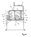
- the shaft seal after Fig. 10 has the elastomeric element 7, which rests with its sealing lip 14 on the outside of the barrel sleeve 1.
- the sealing lip 14 has a sealing edge 22, with which it rests on the barrel sleeve 1.
- the sealing edge 22 is under radial bias on the barrel sleeve 1.
- the annular spring 17 is provided, which is inserted into the annular groove 18 of the elastomer element 7.
- the receiving space 30 of the elastomer part 7 is formed substantially the same as in the shaft seal after Fig. 8 ,
- the recording room 30 after Fig. 10 is higher in the radial direction than in the embodiment according to Fig.
- the elastomer element 7 forms in this embodiment one of the two sealing elements.
- the elastomer element 7 is supported on the annular flange 8 of the housing 9 and on a support disk 23 which lies in a radial plane and at a distance surrounds the running sleeve 1.
- the support disk 23 may be fixed with its outer edge to the inside of the cylinder part 10 of the housing 9, for example welded, if it consists of metallic material.
- the elastomer element 7 rests with its side facing the elastomer element 7a flat against the support disk 23 whose radial width corresponds to the corresponding radial width of the contact side of the elastomer element 7.
- the free end of the sealing lip 14 does not protrude in the embodiment in the central opening 15 of the annular flange 8.
- the sealing lip 14 may be formed so that, as in the embodiment according to Fig. 8 , in or even through the central opening 15 protrudes. In this case, this free end is still at a sufficient distance from the annular flange 2 of the barrel sleeve. 1
- the sealing element 5a is the same design as in the embodiments of the Fig. 8 and 9 , It has the sealing lip 4 a, which rests on the sleeve 1 under radial prestress.
- the sealing member 5a is held between the elastomeric member 7a and the cover plate 19a formed in accordance with the foregoing embodiments.
- the elastomer element 7a is located between the two support plates 22 and 19a, where it rests flat with its two sides.
- the free end 14a of the elastomer element 7a has an axial distance from the support disk 23.
- the annular spring 17a which is inserted into the annular groove 18a of the elastomer element 7a, exerts a radial biasing force on the sealing lip 4a of the sealing element 5a.
- the sealing lip-like part 16a of the elastomer element 7 covers the sealing lip 4a according to the previous embodiments on its side facing away from the barrel sleeve 1 back.
- the receiving space 30a is corresponding to the receiving space 30a of Fig. 9 educated.
- the support disk 19a has as in the embodiment after Fig. 9 axial distance from the funnel-shaped end 3 of the barrel sleeve 1.
- the support disk 19a is fixed to the inside of the cylinder part 10 of the housing 9 in the manner described.
- the shaft seal can have differently designed sealing elements.
- one sealing element is the elastomer element 7 made of elastomeric material, while the other sealing element 5a is polyfluorocarbon, preferably polytetrafluoroethylene.
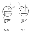
- the Fig. 6 and 7 show shaft seals without sleeve.
- the sealing lip 4 of the sealing element 5 is located directly on the (not shown) shaft.
- the sealing element 5 is located between the elastomer element 7 and the support disk 19, which according to the embodiment according to Fig. 8 are formed and arranged.
- the free end 14 of the sealing lip-shaped part 16 of the elastomer element 7 protrudes through the central opening 15 of the annular flange 8 of the housing 9.
- On the cylinder part 12 of the housing 9 is the sealing means 21, with which the static seal is made.
- the shaft seal after Fig. 6 has no sleeve, it is characterized by a simple structural design.
- the annular spring 17 ensures sufficient radial contact pressure of the sealing lip 4 on the shaft to be sealed.
- the sealing lip 4 of the sealing element 5 is bent in the direction of the medium side 6.
- the support disk 19 rests against the air side 24 facing side of the sealing element 5 according to the previous embodiments.
- the receiving space 30 has the side wall 31, which, in contrast to the previously described embodiments not tangentially, but radially adjoins the wall of the annular groove 18.
- the side wall 31 is then arcuate curved into the wall 32, which in turn connects at an obtuse angle to the end face 33 of the elastomer part 7. Due to the radial connection of the side wall 31 to the wall of the annular groove 18 exercises in the receiving space 30 located medium a radial pressure on the sealing lip-shaped part 16 of the elastomeric part 7 and thus on the sealing lip 4 of the sealing element 5 from.
- the contact pressure of the sealing lip 4 can be achieved by a corresponding hydraulic support via the elastomer part 7.
- By an appropriate design of the receiving space 30 can thus be adjusted in addition to the contact pressure of the sealing lip 4.
- the pressing force distribution can thus be excellently adapted to the application of the shaft seal by an interaction of the design of the profiling 25 and the receiving space 30.
- the elastomer element 7 has in the region of the sealing lip 4 of the sealing element 5 on its support side a profiling 25.
- This profiling is exemplified wave-shaped in axial section.
- the existing between adjacent recesses of the profiling 25 webs are elastically deformed by the force exerted by the annular spring 17 radial pressure.
- the profiling 25 of the sealing lip-shaped part 16 of the elastomer element 7 results in a special force distribution, as is apparent from Fig. 6a results. Here the force distribution over the axial width of the profiling 25 is shown. Due to the webs of the profiling 25 can influence the course of the force distribution.
- the force distribution is not continuous over the axial width of the profiling, but discontinuously in the region of the webs between the recesses of the profiling.
- the course of the radial contact pressure of the sealing lip 4 on the shaft or on the barrel sleeve 1 can be influenced by appropriate design of the profiling 25.
- the radial contact force decreases from the free end of the sealing lip 4 from.
- the sealing lip 4 or the entire sealing element 5 has only a very small thickness, so that this by the profiling 25 as in Fig. 6a shows generated force distribution.
- the embodiment according to Fig. 5 differs from the shaft seal Fig. 6 in that the part 16 of the elastomer element 7 has no profiling and that, for this purpose, the sealing lip 4 of the sealing element 5 is provided on its side facing the shaft to be sealed with a return conveyor device 26. It ensures that between the sealing lip 4 and the shaft reaching medium is conveyed back to the medium side 6.
- the return conveyor 26 may be designed so that it generates the return effect only in one direction of rotation of the shaft. But it is also possible to make the return conveyor 26 so that a return conveyance of the medium in both directions of rotation of the shaft is possible. Since both types of recirculating devices are known, they will not be described in detail.
- the shaft seal is after Fig. 5 the same design as the embodiment according to Fig. 6 ,
- the sealing lip 4 may also have on its outside such a return conveyor. Finally, the return conveyor may be provided only on the outside of the sealing lip 4.
- the embodiment according to Fig. 7 essentially corresponds to the embodiment according to Fig. 5 , The only difference is that the sealing lip 4 of the sealing element 5 has no return conveyor on its shaft support side.
- the embodiment also differs from the embodiment according to Fig. 6 only in that a profiling in the region 16 of the elastomeric part 7 is not provided. How out Fig. 7a This has the consequence that in contrast to the embodiment according to Fig. 6 . 6a a continuous radial contact pressure distribution over the axial width of the sealing lip 4 results. The contact force decreases steadily from the free end of the sealing lip 4 from.
- FIG. 6 . 6a and 7 . 7a shows that by appropriate design of the area 16 of the elastomeric part 7, the force distribution can be optimally adjusted to the particular application.
- the distribution of pressure can be rotational direction dependent or independent.
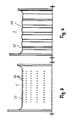
- the Fig. 1 to 4 show different embodiments of the barrel sleeve 1.
- the barrel sleeve 1 has a cylindrical shell 27, which merges at one end into the annular flange 2 and at the other end into the funnel-shaped widened end 3.
- the jacket 27 has a wave-shaped profile which is advantageously provided over the entire axial length of the jacket 27.
- This wave profiling is advantageously designed uniformly, that is, the waves have the same depth and the same axial width.
- the waves may also be formed uneven and / or only over a part of the axial length of the shell 27 may be provided.
- the shaft profiling can be used as a lubricant depot, so that the sealing lip 4 is always lubricated and thus is exposed to only a small amount of wear.
- the jacket 27 of the barrel sleeve 1 according to Fig. 3 may be provided on the outside with a profiling 28 in the form of punctiform depressions. They serve advantageously as lubrication pockets, through which a reliable lubrication of resting on the barrel sleeve 1 sealing lip 4 is ensured.
- Fig. 4 shows an embodiment in which the jacket 27 of the barrel sleeve 1 is provided with a swirl structure 29, through which also a return conveyance of medium in the direction of the medium side 6 is achieved.
- the swirl structure 29 may be formed so that it is effective only in one direction of rotation of the shaft. But it is also possible to make this twist structure 29 so that a direction of rotation independent return conveyance of the medium to be sealed is ensured.
- the swirl structure 29 advantageously extends approximately over the entire axial length of the jacket 27.
- the elastomer elements 7 can also be used without ring springs 17. In these cases, the force exerted by the part 16 of the elastomer element 7 radial force is used to press the sealing lip 4 of the sealing element 5 against the barrel sleeve 1 or directly against the shaft to be sealed.
- the elastomer element 7 is designed in these cases so that their area 16 generates this radial biasing force.
- the sealing lip 4 of the sealing element 5 is always bent in the illustrated embodiments in the direction of the medium side 6. But it is also possible to bend the sealing lip 4 in the direction of the air side 24.
- the sealing lips 4, 4a of both sealing elements 5, 5a can also be directed in the direction of the air side 24. It is also possible that the one sealing lip is directed in the direction of the medium side 6 and the other sealing lip in the direction of the air side 24. The direction in which the sealing lip 4 extends depends on the application of the shaft seal.
- the elastomeric element 7 may be designed differently, as for example from the Fig. 9 and 10 results.
- Fig. 10 can be used instead of the elastomer element 7 with the sealing edge 22 and an elastomeric element 7, as for example in Fig. 9 is shown.
- the part 16 of the elastomer element 7 rests on the running sleeve 1.
- the region 16 of the elastomer element 7 may be provided on its support side with a swirl structure, which ensures a back conveying of the medium to the medium side 6.
- a swirl structure can in turn be designed so that it is effective only in one direction of rotation of the barrel sleeve 1 or the shaft or in both directions of rotation.
- the swirl structures in the sealing lip 4, 4a of the sealing element 5, 5a and / or in the region 16 of the elastomeric element 7 can be embossed, turned, ground, lasered, sprayed and the like.
- the swirl structure may not only be provided on the swirl element 5 and / or on the elastomer element 7, but also on the mating surface, that is, on the jacket 27 of the sleeve 1 or on the shaft to be sealed.
- the barrel sleeves 1 according to the Fig. 1 to 4 in particular the profiled sleeves according to the Fig. 2 to 4 , can also be used in shaft seals, which have a conventional design.
- the use of the sleeves 1 is thus not limited to the described shaft seals.
Landscapes
- Engineering & Computer Science (AREA)
- General Engineering & Computer Science (AREA)
- Mechanical Engineering (AREA)
- Physics & Mathematics (AREA)
- Fluid Mechanics (AREA)
- Sealing With Elastic Sealing Lips (AREA)
- Sealing Devices (AREA)
Applications Claiming Priority (1)
| Application Number | Priority Date | Filing Date | Title |
|---|---|---|---|
| DE102012001226A DE102012001226A1 (de) | 2012-01-19 | 2012-01-19 | Wellendichtung, insbesondere Radialwellendichtung |
Publications (3)
| Publication Number | Publication Date |
|---|---|
| EP2618032A2 true EP2618032A2 (fr) | 2013-07-24 |
| EP2618032A3 EP2618032A3 (fr) | 2014-01-29 |
| EP2618032B1 EP2618032B1 (fr) | 2018-05-23 |
Family
ID=47631244
Family Applications (1)
| Application Number | Title | Priority Date | Filing Date |
|---|---|---|---|
| EP13000228.0A Active EP2618032B1 (fr) | 2012-01-19 | 2013-01-17 | Joint d'étanchéité d'arbre, notamment joint d'arbre radial |
Country Status (5)
| Country | Link |
|---|---|
| US (1) | US9869393B2 (fr) |
| EP (1) | EP2618032B1 (fr) |
| JP (1) | JP6360655B2 (fr) |
| CN (1) | CN103216625B (fr) |
| DE (1) | DE102012001226A1 (fr) |
Cited By (1)
| Publication number | Priority date | Publication date | Assignee | Title |
|---|---|---|---|---|
| WO2018108478A1 (fr) | 2016-12-15 | 2018-06-21 | Universität Stuttgart | Dispositif pour assurer l'étanchéité d'un objet |
Families Citing this family (4)
| Publication number | Priority date | Publication date | Assignee | Title |
|---|---|---|---|---|
| GB201202104D0 (en) * | 2012-02-08 | 2012-03-21 | Rolls Royce Plc | Leaf seal |
| CN109826956B (zh) * | 2019-04-04 | 2023-08-04 | 铁岭五星密封研究所有限公司 | 浮动式双主唇组合密封圈 |
| CN110421292A (zh) * | 2019-08-14 | 2019-11-08 | 异起(上海)智能科技有限公司 | 一种焊接机器人的对目标物体轮廓定位的方法和装置 |
| DE102019008984A1 (de) * | 2019-12-23 | 2021-06-24 | Kaco Gmbh + Co. Kg | Wellendichtung, insbesondere Radialwellendichtung, mit wenigstens einem Dichtelement |
Citations (2)
| Publication number | Priority date | Publication date | Assignee | Title |
|---|---|---|---|---|
| JPH0271172U (fr) | 1988-11-16 | 1990-05-30 | ||
| JPH0344268U (fr) | 1989-09-11 | 1991-04-24 |
Family Cites Families (39)
| Publication number | Priority date | Publication date | Assignee | Title |
|---|---|---|---|---|
| US2316941A (en) * | 1941-04-19 | 1943-04-20 | Gen Tire & Rubber Co | Oil seal |
| US3099454A (en) * | 1961-05-05 | 1963-07-30 | Victor Mfg & Gasket Co | Fluid seal |
| IT1053388B (it) * | 1975-02-20 | 1981-08-31 | Garlock Inc | Perfezionamento nei dispositivi di tenuta per alberi ruotanti |
| GB2066384B (en) * | 1979-12-21 | 1983-08-17 | Fenner Co Ltd J H | Shaft seals |
| JPS61172258A (ja) | 1985-01-25 | 1986-08-02 | Pioneer Electronic Corp | デイスクプレ−ヤにおけるクランプ機構 |
| JPH0242923Y2 (fr) * | 1985-04-16 | 1990-11-15 | ||
| KR890004033B1 (ko) * | 1985-04-16 | 1989-10-16 | 에누오우케이 가부시끼가이샤 | 레이디얼 오일 시일 |
| GB8523892D0 (en) * | 1985-09-27 | 1985-10-30 | Fenner Co Ltd J H | Fluid seals |
| JPH01146066U (fr) * | 1988-03-31 | 1989-10-06 | ||
| JPH0250564U (fr) * | 1988-10-05 | 1990-04-09 | ||
| JP3068170B2 (ja) * | 1990-10-19 | 2000-07-24 | 三菱電線工業株式会社 | オイルシール |
| AU2521692A (en) * | 1991-09-30 | 1993-04-01 | Skf Usa Inc. | Pumping feature on wear sleeve for unitized seal |
| JP2996558B2 (ja) * | 1991-11-29 | 2000-01-11 | 三菱電線工業株式会社 | 回転用シール |
| KR100279109B1 (ko) * | 1993-04-09 | 2001-03-02 | 후지 하루노스케 | 회전축 시일 |
| JP2847277B2 (ja) * | 1993-04-09 | 1999-01-13 | 三菱電線工業株式会社 | 回転軸シール |
| US5553866A (en) * | 1994-11-30 | 1996-09-10 | Freudenberg-Nok General Partnership | Cartridge-type lip seal with removable spacer |
| WO1998002681A1 (fr) * | 1996-07-17 | 1998-01-22 | Kabushiki Kaisha Toyoda Jidoshokki Seisakusho | Structure d'etancheite pour arbre de compresseur |
| US6170833B1 (en) * | 1997-10-24 | 2001-01-09 | Stemco Inc | Hub seal with machinable thrust ring and lay-down sealing lip |
| US6209879B1 (en) * | 1997-10-24 | 2001-04-03 | Eagle Industry Co., Ltd. | Sealing apparatus |
| JPH11270697A (ja) * | 1998-03-23 | 1999-10-05 | Nok Corp | オイルシール |
| US6367811B1 (en) * | 1998-11-24 | 2002-04-09 | Mitsubishi Cable Industries, Ltd. | Rotation shaft seal |
| AU5426200A (en) * | 1999-06-18 | 2001-01-09 | Nok Corporation | Lip-type high-pressure seal |
| JP2001124214A (ja) * | 1999-10-27 | 2001-05-11 | Nok Corp | 密封装置および密封装置の装着方法 |
| EP1146265A2 (fr) * | 2000-04-12 | 2001-10-17 | Mitsubishi Cable Industries, Ltd. | Joint à lèvres |
| JP2001317635A (ja) * | 2000-05-02 | 2001-11-16 | Toyota Industries Corp | リップ型シール |
| JP4648514B2 (ja) * | 2000-05-02 | 2011-03-09 | イーグル工業株式会社 | リップ型シール |
| JP2002005305A (ja) * | 2000-06-21 | 2002-01-09 | Mitsubishi Cable Ind Ltd | 回転軸シール |
| DE10315370A1 (de) * | 2003-04-03 | 2004-11-18 | Carl Freudenberg Kg | Kassettendichtung |
| US7467797B2 (en) * | 2003-04-07 | 2008-12-23 | Eagle Industry Co., Ltd. | Lip-type seal |
| JP2005090569A (ja) * | 2003-09-16 | 2005-04-07 | Nok Corp | 往復動軸用密封装置 |
| JP2006183852A (ja) * | 2004-12-28 | 2006-07-13 | Eagle Ind Co Ltd | 軸封装置 |
| JP4865571B2 (ja) * | 2004-12-28 | 2012-02-01 | イーグル工業株式会社 | 軸封装置 |
| DE102006026812B4 (de) | 2006-06-09 | 2016-04-07 | Ab Skf | Dichtung für einen Kompressor |
| DE102008010338A1 (de) * | 2007-08-02 | 2009-02-05 | Kaco Gmbh + Co. Kg | Radialwellendichtung für Kraftfahrzeug-Wasserpumpen |
| JP2009197883A (ja) * | 2008-02-21 | 2009-09-03 | Ntn Corp | 車輪用軸受装置 |
| US8096559B2 (en) * | 2008-05-23 | 2012-01-17 | Bal Seal Engineering, Inc. | Rotary seals |
| CN101842622B (zh) * | 2008-11-27 | 2014-01-15 | 伊格尔工业股份有限公司 | 唇式密封件 |
| US8684362B2 (en) * | 2009-08-12 | 2014-04-01 | Bal Seal Engineering, Inc. | Cartridge seal assemblies and associated methods |
| WO2012032678A1 (fr) * | 2010-09-11 | 2012-03-15 | イーグル工業株式会社 | Dispositif de joint d'arbre |
-
2012
- 2012-01-19 DE DE102012001226A patent/DE102012001226A1/de not_active Withdrawn
- 2012-07-02 CN CN201210228268.1A patent/CN103216625B/zh active Active
-
2013
- 2013-01-17 EP EP13000228.0A patent/EP2618032B1/fr active Active
- 2013-01-18 US US13/744,746 patent/US9869393B2/en active Active
- 2013-01-18 JP JP2013007407A patent/JP6360655B2/ja active Active
Patent Citations (2)
| Publication number | Priority date | Publication date | Assignee | Title |
|---|---|---|---|---|
| JPH0271172U (fr) | 1988-11-16 | 1990-05-30 | ||
| JPH0344268U (fr) | 1989-09-11 | 1991-04-24 |
Cited By (3)
| Publication number | Priority date | Publication date | Assignee | Title |
|---|---|---|---|---|
| WO2018108478A1 (fr) | 2016-12-15 | 2018-06-21 | Universität Stuttgart | Dispositif pour assurer l'étanchéité d'un objet |
| EP3555503B1 (fr) * | 2016-12-15 | 2021-08-04 | Universität Stuttgart | Dispositif pour assurer l'étanchéité d'un objet |
| KR20230020005A (ko) * | 2016-12-15 | 2023-02-09 | 우니베르지테트 스튜트가르트 | 대상물 밀봉 장치 |
Also Published As
| Publication number | Publication date |
|---|---|
| JP2013148219A (ja) | 2013-08-01 |
| JP6360655B2 (ja) | 2018-07-18 |
| CN103216625B (zh) | 2017-02-15 |
| US20130193649A1 (en) | 2013-08-01 |
| CN103216625A (zh) | 2013-07-24 |
| EP2618032A3 (fr) | 2014-01-29 |
| US9869393B2 (en) | 2018-01-16 |
| EP2618032B1 (fr) | 2018-05-23 |
| DE102012001226A1 (de) | 2013-07-25 |
Similar Documents
| Publication | Publication Date | Title |
|---|---|---|
| DE102007050349B4 (de) | Dichtungsanordnung für den Hochdruckbereich | |
| EP0525288B1 (fr) | Joint en cartouche | |
| EP2306052B1 (fr) | Joint mécanique | |
| EP0431263A1 (fr) | Cartouche d'étanchéité | |
| EP2618032B1 (fr) | Joint d'étanchéité d'arbre, notamment joint d'arbre radial | |
| EP2817539B1 (fr) | Joint radial d'arbre | |
| DE2754168A1 (de) | Wellendichtung | |
| DE102008030710A1 (de) | Kassettendichtung | |
| DE102008010338A1 (de) | Radialwellendichtung für Kraftfahrzeug-Wasserpumpen | |
| EP0091983A1 (fr) | Cartouche d'étanchéité | |
| EP1795787A1 (fr) | Dispositif d'étanchéité | |
| DE102010015200A1 (de) | Kasettendichtung | |
| DE102014203520A1 (de) | Wälzlager mit Dichtung | |
| DE4225556A1 (de) | Zwischen radial nach innen weisenden Vorsprüngen einer Zylinderfläche abgestützte Stangenführung | |
| EP0116721B1 (fr) | Joint d'arbre | |
| DE102009056365A1 (de) | Ausrücklager für eine Kupplung | |
| DE102016006106B4 (de) | Gleitringdichtung | |
| EP1041322B1 (fr) | Garniture mécanique d'étanchéité | |
| DE2921669A1 (de) | Dichtung | |
| EP3842671B1 (fr) | Joint d'étanchéité d'arbre, en particulier joint d'étanchéité d'arbre radial, pourvu d'au moins un élément d'étanchéité | |
| DE102016015553B4 (de) | Radialwellendichtung | |
| EP3417192B1 (fr) | Joint d'arbre | |
| DE102017011541A1 (de) | Dichtung, insbesondere Radialwellendichtung, und Verfahren zum Abdichten, insbesondere unter Verwendung einer solchen Dichtung | |
| DE102008010341A1 (de) | Radialwellendichtung | |
| DE102022212637A1 (de) | Dichtungsanordnung und Antriebseinheit beinhaltend eine Dichtungsanordnung |
Legal Events
| Date | Code | Title | Description |
|---|---|---|---|
| PUAI | Public reference made under article 153(3) epc to a published international application that has entered the european phase |
Free format text: ORIGINAL CODE: 0009012 |
|
| AK | Designated contracting states |
Kind code of ref document: A2 Designated state(s): AL AT BE BG CH CY CZ DE DK EE ES FI FR GB GR HR HU IE IS IT LI LT LU LV MC MK MT NL NO PL PT RO RS SE SI SK SM TR |
|
| AX | Request for extension of the european patent |
Extension state: BA ME |
|
| TPAC | Observations filed by third parties |
Free format text: ORIGINAL CODE: EPIDOSNTIPA |
|
| PUAL | Search report despatched |
Free format text: ORIGINAL CODE: 0009013 |
|
| AK | Designated contracting states |
Kind code of ref document: A3 Designated state(s): AL AT BE BG CH CY CZ DE DK EE ES FI FR GB GR HR HU IE IS IT LI LT LU LV MC MK MT NL NO PL PT RO RS SE SI SK SM TR |
|
| AX | Request for extension of the european patent |
Extension state: BA ME |
|
| RIC1 | Information provided on ipc code assigned before grant |
Ipc: F16J 15/32 20060101AFI20131220BHEP |
|
| 17P | Request for examination filed |
Effective date: 20140729 |
|
| RBV | Designated contracting states (corrected) |
Designated state(s): AL AT BE BG CH CY CZ DE DK EE ES FI FR GB GR HR HU IE IS IT LI LT LU LV MC MK MT NL NO PL PT RO RS SE SI SK SM TR |
|
| 17Q | First examination report despatched |
Effective date: 20160329 |
|
| STAA | Information on the status of an ep patent application or granted ep patent |
Free format text: STATUS: EXAMINATION IS IN PROGRESS |
|
| REG | Reference to a national code |
Ref country code: DE Ref legal event code: R079 Ref document number: 502013010177 Country of ref document: DE Free format text: PREVIOUS MAIN CLASS: F16J0015320000 Ipc: F16J0015320800 |
|
| RIC1 | Information provided on ipc code assigned before grant |
Ipc: F16J 15/324 20160101ALI20171031BHEP Ipc: F16J 15/3228 20160101ALI20171031BHEP Ipc: F16J 15/3208 20160101AFI20171031BHEP Ipc: F16J 15/3232 20160101ALI20171031BHEP Ipc: F16J 15/3244 20160101ALI20171031BHEP |
|
| GRAP | Despatch of communication of intention to grant a patent |
Free format text: ORIGINAL CODE: EPIDOSNIGR1 |
|
| STAA | Information on the status of an ep patent application or granted ep patent |
Free format text: STATUS: GRANT OF PATENT IS INTENDED |
|
| INTG | Intention to grant announced |
Effective date: 20171208 |
|
| GRAS | Grant fee paid |
Free format text: ORIGINAL CODE: EPIDOSNIGR3 |
|
| GRAA | (expected) grant |
Free format text: ORIGINAL CODE: 0009210 |
|
| STAA | Information on the status of an ep patent application or granted ep patent |
Free format text: STATUS: THE PATENT HAS BEEN GRANTED |
|
| AK | Designated contracting states |
Kind code of ref document: B1 Designated state(s): AL AT BE BG CH CY CZ DE DK EE ES FI FR GB GR HR HU IE IS IT LI LT LU LV MC MK MT NL NO PL PT RO RS SE SI SK SM TR |
|
| REG | Reference to a national code |
Ref country code: GB Ref legal event code: FG4D Free format text: NOT ENGLISH |
|
| REG | Reference to a national code |
Ref country code: CH Ref legal event code: EP |
|
| REG | Reference to a national code |
Ref country code: IE Ref legal event code: FG4D Free format text: LANGUAGE OF EP DOCUMENT: GERMAN |
|
| REG | Reference to a national code |
Ref country code: DE Ref legal event code: R096 Ref document number: 502013010177 Country of ref document: DE |
|
| REG | Reference to a national code |
Ref country code: AT Ref legal event code: REF Ref document number: 1001784 Country of ref document: AT Kind code of ref document: T Effective date: 20180615 |
|
| REG | Reference to a national code |
Ref country code: NL Ref legal event code: MP Effective date: 20180523 |
|
| REG | Reference to a national code |
Ref country code: LT Ref legal event code: MG4D |
|
| PG25 | Lapsed in a contracting state [announced via postgrant information from national office to epo] |
Ref country code: FI Free format text: LAPSE BECAUSE OF FAILURE TO SUBMIT A TRANSLATION OF THE DESCRIPTION OR TO PAY THE FEE WITHIN THE PRESCRIBED TIME-LIMIT Effective date: 20180523 Ref country code: NO Free format text: LAPSE BECAUSE OF FAILURE TO SUBMIT A TRANSLATION OF THE DESCRIPTION OR TO PAY THE FEE WITHIN THE PRESCRIBED TIME-LIMIT Effective date: 20180823 Ref country code: LT Free format text: LAPSE BECAUSE OF FAILURE TO SUBMIT A TRANSLATION OF THE DESCRIPTION OR TO PAY THE FEE WITHIN THE PRESCRIBED TIME-LIMIT Effective date: 20180523 Ref country code: ES Free format text: LAPSE BECAUSE OF FAILURE TO SUBMIT A TRANSLATION OF THE DESCRIPTION OR TO PAY THE FEE WITHIN THE PRESCRIBED TIME-LIMIT Effective date: 20180523 Ref country code: SE Free format text: LAPSE BECAUSE OF FAILURE TO SUBMIT A TRANSLATION OF THE DESCRIPTION OR TO PAY THE FEE WITHIN THE PRESCRIBED TIME-LIMIT Effective date: 20180523 Ref country code: BG Free format text: LAPSE BECAUSE OF FAILURE TO SUBMIT A TRANSLATION OF THE DESCRIPTION OR TO PAY THE FEE WITHIN THE PRESCRIBED TIME-LIMIT Effective date: 20180823 |
|
| PG25 | Lapsed in a contracting state [announced via postgrant information from national office to epo] |
Ref country code: LV Free format text: LAPSE BECAUSE OF FAILURE TO SUBMIT A TRANSLATION OF THE DESCRIPTION OR TO PAY THE FEE WITHIN THE PRESCRIBED TIME-LIMIT Effective date: 20180523 Ref country code: NL Free format text: LAPSE BECAUSE OF FAILURE TO SUBMIT A TRANSLATION OF THE DESCRIPTION OR TO PAY THE FEE WITHIN THE PRESCRIBED TIME-LIMIT Effective date: 20180523 Ref country code: RS Free format text: LAPSE BECAUSE OF FAILURE TO SUBMIT A TRANSLATION OF THE DESCRIPTION OR TO PAY THE FEE WITHIN THE PRESCRIBED TIME-LIMIT Effective date: 20180523 Ref country code: GR Free format text: LAPSE BECAUSE OF FAILURE TO SUBMIT A TRANSLATION OF THE DESCRIPTION OR TO PAY THE FEE WITHIN THE PRESCRIBED TIME-LIMIT Effective date: 20180824 Ref country code: HR Free format text: LAPSE BECAUSE OF FAILURE TO SUBMIT A TRANSLATION OF THE DESCRIPTION OR TO PAY THE FEE WITHIN THE PRESCRIBED TIME-LIMIT Effective date: 20180523 |
|
| REG | Reference to a national code |
Ref country code: CH Ref legal event code: PK Free format text: BERICHTIGUNGEN |
|
| RIC2 | Information provided on ipc code assigned after grant |
Ipc: F16J 15/324 20160101ALI20171031BHEP Ipc: F16J 15/3232 20160101ALI20171031BHEP Ipc: F16J 15/3228 20160101ALI20171031BHEP Ipc: F16J 15/3244 20160101ALI20171031BHEP Ipc: F16J 15/3208 20160101AFI20171031BHEP |
|
| REG | Reference to a national code |
Ref country code: DE Ref legal event code: R081 Ref document number: 502013010177 Country of ref document: DE Owner name: KACO GMBH + CO. KG, DE Free format text: FORMER OWNER: KACO GMBH + CO. KG, 74072 HEILBRONN, DE Ref country code: DE Ref legal event code: R082 Ref document number: 502013010177 Country of ref document: DE Representative=s name: JACKISCH-KOHL UND KOHL, DE |
|
| PG25 | Lapsed in a contracting state [announced via postgrant information from national office to epo] |
Ref country code: PL Free format text: LAPSE BECAUSE OF FAILURE TO SUBMIT A TRANSLATION OF THE DESCRIPTION OR TO PAY THE FEE WITHIN THE PRESCRIBED TIME-LIMIT Effective date: 20180523 Ref country code: DK Free format text: LAPSE BECAUSE OF FAILURE TO SUBMIT A TRANSLATION OF THE DESCRIPTION OR TO PAY THE FEE WITHIN THE PRESCRIBED TIME-LIMIT Effective date: 20180523 Ref country code: EE Free format text: LAPSE BECAUSE OF FAILURE TO SUBMIT A TRANSLATION OF THE DESCRIPTION OR TO PAY THE FEE WITHIN THE PRESCRIBED TIME-LIMIT Effective date: 20180523 Ref country code: SK Free format text: LAPSE BECAUSE OF FAILURE TO SUBMIT A TRANSLATION OF THE DESCRIPTION OR TO PAY THE FEE WITHIN THE PRESCRIBED TIME-LIMIT Effective date: 20180523 Ref country code: RO Free format text: LAPSE BECAUSE OF FAILURE TO SUBMIT A TRANSLATION OF THE DESCRIPTION OR TO PAY THE FEE WITHIN THE PRESCRIBED TIME-LIMIT Effective date: 20180523 Ref country code: CZ Free format text: LAPSE BECAUSE OF FAILURE TO SUBMIT A TRANSLATION OF THE DESCRIPTION OR TO PAY THE FEE WITHIN THE PRESCRIBED TIME-LIMIT Effective date: 20180523 |
|
| REG | Reference to a national code |
Ref country code: CH Ref legal event code: PK Free format text: BERICHTIGUNGEN |
|
| RIC2 | Information provided on ipc code assigned after grant |
Ipc: F16J 15/3208 20160101AFI20171031BHEP Ipc: F16J 15/3232 20160101ALI20171031BHEP Ipc: F16J 15/3244 20160101ALI20171031BHEP Ipc: F16J 15/324 20160101ALI20171031BHEP Ipc: F16J 15/3228 20160101ALI20171031BHEP |
|
| REG | Reference to a national code |
Ref country code: DE Ref legal event code: R097 Ref document number: 502013010177 Country of ref document: DE |
|
| PG25 | Lapsed in a contracting state [announced via postgrant information from national office to epo] |
Ref country code: SM Free format text: LAPSE BECAUSE OF FAILURE TO SUBMIT A TRANSLATION OF THE DESCRIPTION OR TO PAY THE FEE WITHIN THE PRESCRIBED TIME-LIMIT Effective date: 20180523 |
|
| PLBE | No opposition filed within time limit |
Free format text: ORIGINAL CODE: 0009261 |
|
| STAA | Information on the status of an ep patent application or granted ep patent |
Free format text: STATUS: NO OPPOSITION FILED WITHIN TIME LIMIT |
|
| 26N | No opposition filed |
Effective date: 20190226 |
|
| PG25 | Lapsed in a contracting state [announced via postgrant information from national office to epo] |
Ref country code: SI Free format text: LAPSE BECAUSE OF FAILURE TO SUBMIT A TRANSLATION OF THE DESCRIPTION OR TO PAY THE FEE WITHIN THE PRESCRIBED TIME-LIMIT Effective date: 20180523 |
|
| PG25 | Lapsed in a contracting state [announced via postgrant information from national office to epo] |
Ref country code: MC Free format text: LAPSE BECAUSE OF FAILURE TO SUBMIT A TRANSLATION OF THE DESCRIPTION OR TO PAY THE FEE WITHIN THE PRESCRIBED TIME-LIMIT Effective date: 20180523 |
|
| REG | Reference to a national code |
Ref country code: CH Ref legal event code: PL |
|
| GBPC | Gb: european patent ceased through non-payment of renewal fee |
Effective date: 20190117 |
|
| PG25 | Lapsed in a contracting state [announced via postgrant information from national office to epo] |
Ref country code: LU Free format text: LAPSE BECAUSE OF NON-PAYMENT OF DUE FEES Effective date: 20190117 |
|
| REG | Reference to a national code |
Ref country code: BE Ref legal event code: MM Effective date: 20190131 |
|
| REG | Reference to a national code |
Ref country code: IE Ref legal event code: MM4A |
|
| PG25 | Lapsed in a contracting state [announced via postgrant information from national office to epo] |
Ref country code: BE Free format text: LAPSE BECAUSE OF NON-PAYMENT OF DUE FEES Effective date: 20190131 Ref country code: AL Free format text: LAPSE BECAUSE OF FAILURE TO SUBMIT A TRANSLATION OF THE DESCRIPTION OR TO PAY THE FEE WITHIN THE PRESCRIBED TIME-LIMIT Effective date: 20180523 |
|
| PG25 | Lapsed in a contracting state [announced via postgrant information from national office to epo] |
Ref country code: CH Free format text: LAPSE BECAUSE OF NON-PAYMENT OF DUE FEES Effective date: 20190131 Ref country code: GB Free format text: LAPSE BECAUSE OF NON-PAYMENT OF DUE FEES Effective date: 20190117 Ref country code: LI Free format text: LAPSE BECAUSE OF NON-PAYMENT OF DUE FEES Effective date: 20190131 |
|
| PG25 | Lapsed in a contracting state [announced via postgrant information from national office to epo] |
Ref country code: IE Free format text: LAPSE BECAUSE OF NON-PAYMENT OF DUE FEES Effective date: 20190117 |
|
| REG | Reference to a national code |
Ref country code: AT Ref legal event code: MM01 Ref document number: 1001784 Country of ref document: AT Kind code of ref document: T Effective date: 20190117 |
|
| PG25 | Lapsed in a contracting state [announced via postgrant information from national office to epo] |
Ref country code: TR Free format text: LAPSE BECAUSE OF FAILURE TO SUBMIT A TRANSLATION OF THE DESCRIPTION OR TO PAY THE FEE WITHIN THE PRESCRIBED TIME-LIMIT Effective date: 20180523 |
|
| PG25 | Lapsed in a contracting state [announced via postgrant information from national office to epo] |
Ref country code: AT Free format text: LAPSE BECAUSE OF NON-PAYMENT OF DUE FEES Effective date: 20190117 |
|
| PG25 | Lapsed in a contracting state [announced via postgrant information from national office to epo] |
Ref country code: PT Free format text: LAPSE BECAUSE OF FAILURE TO SUBMIT A TRANSLATION OF THE DESCRIPTION OR TO PAY THE FEE WITHIN THE PRESCRIBED TIME-LIMIT Effective date: 20180924 Ref country code: MT Free format text: LAPSE BECAUSE OF FAILURE TO SUBMIT A TRANSLATION OF THE DESCRIPTION OR TO PAY THE FEE WITHIN THE PRESCRIBED TIME-LIMIT Effective date: 20180523 |
|
| PG25 | Lapsed in a contracting state [announced via postgrant information from national office to epo] |
Ref country code: CY Free format text: LAPSE BECAUSE OF FAILURE TO SUBMIT A TRANSLATION OF THE DESCRIPTION OR TO PAY THE FEE WITHIN THE PRESCRIBED TIME-LIMIT Effective date: 20180523 |
|
| PG25 | Lapsed in a contracting state [announced via postgrant information from national office to epo] |
Ref country code: IS Free format text: LAPSE BECAUSE OF FAILURE TO SUBMIT A TRANSLATION OF THE DESCRIPTION OR TO PAY THE FEE WITHIN THE PRESCRIBED TIME-LIMIT Effective date: 20180923 |
|
| PG25 | Lapsed in a contracting state [announced via postgrant information from national office to epo] |
Ref country code: HU Free format text: LAPSE BECAUSE OF FAILURE TO SUBMIT A TRANSLATION OF THE DESCRIPTION OR TO PAY THE FEE WITHIN THE PRESCRIBED TIME-LIMIT; INVALID AB INITIO Effective date: 20130117 |
|
| PG25 | Lapsed in a contracting state [announced via postgrant information from national office to epo] |
Ref country code: MK Free format text: LAPSE BECAUSE OF FAILURE TO SUBMIT A TRANSLATION OF THE DESCRIPTION OR TO PAY THE FEE WITHIN THE PRESCRIBED TIME-LIMIT Effective date: 20180523 |
|
| PGFP | Annual fee paid to national office [announced via postgrant information from national office to epo] |
Ref country code: FR Payment date: 20221118 Year of fee payment: 11 |
|
| PGFP | Annual fee paid to national office [announced via postgrant information from national office to epo] |
Ref country code: IT Payment date: 20230112 Year of fee payment: 11 |
|
| PGFP | Annual fee paid to national office [announced via postgrant information from national office to epo] |
Ref country code: DE Payment date: 20240118 Year of fee payment: 12 |