EP2617552B1 - Elektroschweißmuffe - Google Patents
Elektroschweißmuffe Download PDFInfo
- Publication number
- EP2617552B1 EP2617552B1 EP12180932.1A EP12180932A EP2617552B1 EP 2617552 B1 EP2617552 B1 EP 2617552B1 EP 12180932 A EP12180932 A EP 12180932A EP 2617552 B1 EP2617552 B1 EP 2617552B1
- Authority
- EP
- European Patent Office
- Prior art keywords
- grip ring
- opening
- terminal pin
- fitting
- electrofusion
- Prior art date
- Legal status (The legal status is an assumption and is not a legal conclusion. Google has not performed a legal analysis and makes no representation as to the accuracy of the status listed.)
- Not-in-force
Links
- 229920003023 plastic Polymers 0.000 claims description 13
- 239000004033 plastic Substances 0.000 claims description 13
- 230000004323 axial length Effects 0.000 claims description 5
- 238000003780 insertion Methods 0.000 claims description 4
- 230000037431 insertion Effects 0.000 claims description 4
- 230000001419 dependent effect Effects 0.000 claims 1
- 230000004927 fusion Effects 0.000 description 15
- 238000002844 melting Methods 0.000 description 5
- 230000008018 melting Effects 0.000 description 5
- 230000035515 penetration Effects 0.000 description 5
- 239000004020 conductor Substances 0.000 description 3
- 230000008878 coupling Effects 0.000 description 3
- 238000010168 coupling process Methods 0.000 description 3
- 238000005859 coupling reaction Methods 0.000 description 3
- 239000000463 material Substances 0.000 description 3
- 238000010079 rubber tapping Methods 0.000 description 3
- 230000008859 change Effects 0.000 description 2
- 239000012943 hotmelt Substances 0.000 description 2
- 238000004519 manufacturing process Methods 0.000 description 2
- 230000013011 mating Effects 0.000 description 2
- 239000000155 melt Substances 0.000 description 2
- 230000000750 progressive effect Effects 0.000 description 2
- 238000003466 welding Methods 0.000 description 2
- 238000004804 winding Methods 0.000 description 2
- 230000009471 action Effects 0.000 description 1
- 239000012530 fluid Substances 0.000 description 1
- 230000008014 freezing Effects 0.000 description 1
- 238000007710 freezing Methods 0.000 description 1
- 238000007499 fusion processing Methods 0.000 description 1
- 238000005304 joining Methods 0.000 description 1
- 239000002861 polymer material Substances 0.000 description 1
- 230000002226 simultaneous effect Effects 0.000 description 1
- 230000003313 weakening effect Effects 0.000 description 1
Images

Classifications
-
- B—PERFORMING OPERATIONS; TRANSPORTING
- B29—WORKING OF PLASTICS; WORKING OF SUBSTANCES IN A PLASTIC STATE IN GENERAL
- B29C—SHAPING OR JOINING OF PLASTICS; SHAPING OF MATERIAL IN A PLASTIC STATE, NOT OTHERWISE PROVIDED FOR; AFTER-TREATMENT OF THE SHAPED PRODUCTS, e.g. REPAIRING
- B29C65/00—Joining or sealing of preformed parts, e.g. welding of plastics materials; Apparatus therefor
- B29C65/02—Joining or sealing of preformed parts, e.g. welding of plastics materials; Apparatus therefor by heating, with or without pressure
- B29C65/34—Joining or sealing of preformed parts, e.g. welding of plastics materials; Apparatus therefor by heating, with or without pressure using heated elements which remain in the joint, e.g. "verlorenes Schweisselement"
- B29C65/3472—Joining or sealing of preformed parts, e.g. welding of plastics materials; Apparatus therefor by heating, with or without pressure using heated elements which remain in the joint, e.g. "verlorenes Schweisselement" characterised by the composition of the heated elements which remain in the joint
- B29C65/3476—Joining or sealing of preformed parts, e.g. welding of plastics materials; Apparatus therefor by heating, with or without pressure using heated elements which remain in the joint, e.g. "verlorenes Schweisselement" characterised by the composition of the heated elements which remain in the joint being metallic
-
- B—PERFORMING OPERATIONS; TRANSPORTING
- B29—WORKING OF PLASTICS; WORKING OF SUBSTANCES IN A PLASTIC STATE IN GENERAL
- B29C—SHAPING OR JOINING OF PLASTICS; SHAPING OF MATERIAL IN A PLASTIC STATE, NOT OTHERWISE PROVIDED FOR; AFTER-TREATMENT OF THE SHAPED PRODUCTS, e.g. REPAIRING
- B29C65/00—Joining or sealing of preformed parts, e.g. welding of plastics materials; Apparatus therefor
- B29C65/02—Joining or sealing of preformed parts, e.g. welding of plastics materials; Apparatus therefor by heating, with or without pressure
- B29C65/34—Joining or sealing of preformed parts, e.g. welding of plastics materials; Apparatus therefor by heating, with or without pressure using heated elements which remain in the joint, e.g. "verlorenes Schweisselement"
- B29C65/3404—Joining or sealing of preformed parts, e.g. welding of plastics materials; Apparatus therefor by heating, with or without pressure using heated elements which remain in the joint, e.g. "verlorenes Schweisselement" characterised by the type of heated elements which remain in the joint
- B29C65/342—Joining or sealing of preformed parts, e.g. welding of plastics materials; Apparatus therefor by heating, with or without pressure using heated elements which remain in the joint, e.g. "verlorenes Schweisselement" characterised by the type of heated elements which remain in the joint comprising at least a single wire, e.g. in the form of a winding
-
- B—PERFORMING OPERATIONS; TRANSPORTING
- B29—WORKING OF PLASTICS; WORKING OF SUBSTANCES IN A PLASTIC STATE IN GENERAL
- B29C—SHAPING OR JOINING OF PLASTICS; SHAPING OF MATERIAL IN A PLASTIC STATE, NOT OTHERWISE PROVIDED FOR; AFTER-TREATMENT OF THE SHAPED PRODUCTS, e.g. REPAIRING
- B29C65/00—Joining or sealing of preformed parts, e.g. welding of plastics materials; Apparatus therefor
- B29C65/02—Joining or sealing of preformed parts, e.g. welding of plastics materials; Apparatus therefor by heating, with or without pressure
- B29C65/34—Joining or sealing of preformed parts, e.g. welding of plastics materials; Apparatus therefor by heating, with or without pressure using heated elements which remain in the joint, e.g. "verlorenes Schweisselement"
- B29C65/3468—Joining or sealing of preformed parts, e.g. welding of plastics materials; Apparatus therefor by heating, with or without pressure using heated elements which remain in the joint, e.g. "verlorenes Schweisselement" characterised by the means for supplying heat to said heated elements which remain in the join, e.g. special electrical connectors of windings
-
- B—PERFORMING OPERATIONS; TRANSPORTING
- B29—WORKING OF PLASTICS; WORKING OF SUBSTANCES IN A PLASTIC STATE IN GENERAL
- B29C—SHAPING OR JOINING OF PLASTICS; SHAPING OF MATERIAL IN A PLASTIC STATE, NOT OTHERWISE PROVIDED FOR; AFTER-TREATMENT OF THE SHAPED PRODUCTS, e.g. REPAIRING
- B29C66/00—General aspects of processes or apparatus for joining preformed parts
- B29C66/01—General aspects dealing with the joint area or with the area to be joined
- B29C66/05—Particular design of joint configurations
- B29C66/10—Particular design of joint configurations particular design of the joint cross-sections
- B29C66/12—Joint cross-sections combining only two joint-segments; Tongue and groove joints; Tenon and mortise joints; Stepped joint cross-sections
- B29C66/122—Joint cross-sections combining only two joint-segments, i.e. one of the parts to be joined comprising only two joint-segments in the joint cross-section
- B29C66/1222—Joint cross-sections combining only two joint-segments, i.e. one of the parts to be joined comprising only two joint-segments in the joint cross-section comprising at least a lapped joint-segment
-
- B—PERFORMING OPERATIONS; TRANSPORTING
- B29—WORKING OF PLASTICS; WORKING OF SUBSTANCES IN A PLASTIC STATE IN GENERAL
- B29C—SHAPING OR JOINING OF PLASTICS; SHAPING OF MATERIAL IN A PLASTIC STATE, NOT OTHERWISE PROVIDED FOR; AFTER-TREATMENT OF THE SHAPED PRODUCTS, e.g. REPAIRING
- B29C66/00—General aspects of processes or apparatus for joining preformed parts
- B29C66/01—General aspects dealing with the joint area or with the area to be joined
- B29C66/05—Particular design of joint configurations
- B29C66/10—Particular design of joint configurations particular design of the joint cross-sections
- B29C66/12—Joint cross-sections combining only two joint-segments; Tongue and groove joints; Tenon and mortise joints; Stepped joint cross-sections
- B29C66/122—Joint cross-sections combining only two joint-segments, i.e. one of the parts to be joined comprising only two joint-segments in the joint cross-section
- B29C66/1224—Joint cross-sections combining only two joint-segments, i.e. one of the parts to be joined comprising only two joint-segments in the joint cross-section comprising at least a butt joint-segment
-
- B—PERFORMING OPERATIONS; TRANSPORTING
- B29—WORKING OF PLASTICS; WORKING OF SUBSTANCES IN A PLASTIC STATE IN GENERAL
- B29C—SHAPING OR JOINING OF PLASTICS; SHAPING OF MATERIAL IN A PLASTIC STATE, NOT OTHERWISE PROVIDED FOR; AFTER-TREATMENT OF THE SHAPED PRODUCTS, e.g. REPAIRING
- B29C66/00—General aspects of processes or apparatus for joining preformed parts
- B29C66/50—General aspects of joining tubular articles; General aspects of joining long products, i.e. bars or profiled elements; General aspects of joining single elements to tubular articles, hollow articles or bars; General aspects of joining several hollow-preforms to form hollow or tubular articles
- B29C66/51—Joining tubular articles, profiled elements or bars; Joining single elements to tubular articles, hollow articles or bars; Joining several hollow-preforms to form hollow or tubular articles
- B29C66/52—Joining tubular articles, bars or profiled elements
- B29C66/522—Joining tubular articles
- B29C66/5221—Joining tubular articles for forming coaxial connections, i.e. the tubular articles to be joined forming a zero angle relative to each other
-
- B—PERFORMING OPERATIONS; TRANSPORTING
- B29—WORKING OF PLASTICS; WORKING OF SUBSTANCES IN A PLASTIC STATE IN GENERAL
- B29C—SHAPING OR JOINING OF PLASTICS; SHAPING OF MATERIAL IN A PLASTIC STATE, NOT OTHERWISE PROVIDED FOR; AFTER-TREATMENT OF THE SHAPED PRODUCTS, e.g. REPAIRING
- B29C66/00—General aspects of processes or apparatus for joining preformed parts
- B29C66/50—General aspects of joining tubular articles; General aspects of joining long products, i.e. bars or profiled elements; General aspects of joining single elements to tubular articles, hollow articles or bars; General aspects of joining several hollow-preforms to form hollow or tubular articles
- B29C66/51—Joining tubular articles, profiled elements or bars; Joining single elements to tubular articles, hollow articles or bars; Joining several hollow-preforms to form hollow or tubular articles
- B29C66/52—Joining tubular articles, bars or profiled elements
- B29C66/522—Joining tubular articles
- B29C66/5229—Joining tubular articles involving the use of a socket
- B29C66/52297—Joining tubular articles involving the use of a socket said socket comprising slip-off prevention means
-
- B—PERFORMING OPERATIONS; TRANSPORTING
- B29—WORKING OF PLASTICS; WORKING OF SUBSTANCES IN A PLASTIC STATE IN GENERAL
- B29C—SHAPING OR JOINING OF PLASTICS; SHAPING OF MATERIAL IN A PLASTIC STATE, NOT OTHERWISE PROVIDED FOR; AFTER-TREATMENT OF THE SHAPED PRODUCTS, e.g. REPAIRING
- B29C66/00—General aspects of processes or apparatus for joining preformed parts
- B29C66/50—General aspects of joining tubular articles; General aspects of joining long products, i.e. bars or profiled elements; General aspects of joining single elements to tubular articles, hollow articles or bars; General aspects of joining several hollow-preforms to form hollow or tubular articles
- B29C66/51—Joining tubular articles, profiled elements or bars; Joining single elements to tubular articles, hollow articles or bars; Joining several hollow-preforms to form hollow or tubular articles
- B29C66/52—Joining tubular articles, bars or profiled elements
- B29C66/522—Joining tubular articles
- B29C66/5229—Joining tubular articles involving the use of a socket
- B29C66/52298—Joining tubular articles involving the use of a socket said socket being composed by several elements
-
- B—PERFORMING OPERATIONS; TRANSPORTING
- B29—WORKING OF PLASTICS; WORKING OF SUBSTANCES IN A PLASTIC STATE IN GENERAL
- B29C—SHAPING OR JOINING OF PLASTICS; SHAPING OF MATERIAL IN A PLASTIC STATE, NOT OTHERWISE PROVIDED FOR; AFTER-TREATMENT OF THE SHAPED PRODUCTS, e.g. REPAIRING
- B29C66/00—General aspects of processes or apparatus for joining preformed parts
- B29C66/80—General aspects of machine operations or constructions and parts thereof
- B29C66/81—General aspects of the pressing elements, i.e. the elements applying pressure on the parts to be joined in the area to be joined, e.g. the welding jaws or clamps
- B29C66/814—General aspects of the pressing elements, i.e. the elements applying pressure on the parts to be joined in the area to be joined, e.g. the welding jaws or clamps characterised by the design of the pressing elements, e.g. of the welding jaws or clamps
- B29C66/8145—General aspects of the pressing elements, i.e. the elements applying pressure on the parts to be joined in the area to be joined, e.g. the welding jaws or clamps characterised by the design of the pressing elements, e.g. of the welding jaws or clamps characterised by the constructional aspects of the pressing elements, e.g. of the welding jaws or clamps
-
- F—MECHANICAL ENGINEERING; LIGHTING; HEATING; WEAPONS; BLASTING
- F16—ENGINEERING ELEMENTS AND UNITS; GENERAL MEASURES FOR PRODUCING AND MAINTAINING EFFECTIVE FUNCTIONING OF MACHINES OR INSTALLATIONS; THERMAL INSULATION IN GENERAL
- F16L—PIPES; JOINTS OR FITTINGS FOR PIPES; SUPPORTS FOR PIPES, CABLES OR PROTECTIVE TUBING; MEANS FOR THERMAL INSULATION IN GENERAL
- F16L47/00—Connecting arrangements or other fittings specially adapted to be made of plastics or to be used with pipes made of plastics
- F16L47/02—Welded joints; Adhesive joints
- F16L47/03—Welded joints with an electrical resistance incorporated in the joint
-
- B—PERFORMING OPERATIONS; TRANSPORTING
- B29—WORKING OF PLASTICS; WORKING OF SUBSTANCES IN A PLASTIC STATE IN GENERAL
- B29C—SHAPING OR JOINING OF PLASTICS; SHAPING OF MATERIAL IN A PLASTIC STATE, NOT OTHERWISE PROVIDED FOR; AFTER-TREATMENT OF THE SHAPED PRODUCTS, e.g. REPAIRING
- B29C66/00—General aspects of processes or apparatus for joining preformed parts
- B29C66/50—General aspects of joining tubular articles; General aspects of joining long products, i.e. bars or profiled elements; General aspects of joining single elements to tubular articles, hollow articles or bars; General aspects of joining several hollow-preforms to form hollow or tubular articles
- B29C66/51—Joining tubular articles, profiled elements or bars; Joining single elements to tubular articles, hollow articles or bars; Joining several hollow-preforms to form hollow or tubular articles
- B29C66/52—Joining tubular articles, bars or profiled elements
- B29C66/522—Joining tubular articles
- B29C66/5229—Joining tubular articles involving the use of a socket
- B29C66/52291—Joining tubular articles involving the use of a socket said socket comprising a stop
- B29C66/52292—Joining tubular articles involving the use of a socket said socket comprising a stop said stop being internal
-
- B—PERFORMING OPERATIONS; TRANSPORTING
- B29—WORKING OF PLASTICS; WORKING OF SUBSTANCES IN A PLASTIC STATE IN GENERAL
- B29C—SHAPING OR JOINING OF PLASTICS; SHAPING OF MATERIAL IN A PLASTIC STATE, NOT OTHERWISE PROVIDED FOR; AFTER-TREATMENT OF THE SHAPED PRODUCTS, e.g. REPAIRING
- B29C66/00—General aspects of processes or apparatus for joining preformed parts
- B29C66/90—Measuring or controlling the joining process
- B29C66/97—Checking completion of joining or correct joining by using indications on at least one of the joined parts
- B29C66/972—Checking completion of joining or correct joining by using indications on at least one of the joined parts by extrusion of molten material
Definitions
- This invention relates to the field of electrofusion fittings.
- Such fittings are employed to connect together plastics pipelines. They come in many kinds, from simple, inline couplers for two pipes to be joined end-to-end, to more complex fittings such as tapping tees to connect a branch service pipe to a mains pipe.
- electrofusion fittings comprise one or more tubular openings adapted to receive a pipe to be connected to the fitting.
- the tubular opening has an electrofusion element embedded in the internal surface of the opening that lies against the pipe when the pipe is inserted in the fitting.
- the electrofusion element frequently comprises a coil of resistance wire.
- the coil generally begins well inside the mouth of the opening and ends before the end of the fully-inserted pipe.
- a rib or the like forms a stop in the opening, determining when the pipe is fully inserted once its end abuts the stop. This ensures that the element is fully covered on both sides, by the pipe, on the one hand, and by the fitting on the other.
- the plastics material of the pipe and fitting adjacent the electrofusion element melts and fuses.
- Both the pipe and the fitting are sufficiently thick, and being made of plastics material which is a poor conductor of heat, so that the liquefied plastics does not penetrate out through the fitting, or in through the wall of the pipe.
- the melting does not penetrate to the end of the fitting or to the end of the pipe.
- a "cold zone” on either side of (and axially adjacent to) the fusion zone ensures the melting is contained.
- the plastics expands somewhat on melting, so that there is an increase in pressure in the fusion zone that aids fusion.
- An aperture is sometimes provided in the fitting communicating with the bore thereof in the region of the coil, so that melted plastics is exuded through the aperture to indicate melting and probable completion of the weld.
- a successful joint is one where the fitting and pipe are fused in a ring around the fluid passage of the pipe, and over a considerable length of the pipe so that a leakage or fracture path, if one develops, has to penetrate a long distance. This applies both to a tubular fitting and to a saddle fitting. There can be a number of reasons why a joint is not successful, and sometimes the fact that it is unsuccessful is not immediately apparent. Of course, mating surfaces of the fitting and pipe in the region of the electrofusion element have to be clean and "unskinned" (that is, having no oxide layer formed on the surface), otherwise proper fusion, which involves surface mixing between the two parts, may be inhibited.
- the mating surfaces must lie close to one another over the entire fusion range, otherwise they may be too far apart for the liquefied plastics to meet over a long length of the complete circumference of the joint. Finally, there should be no relative movement between the pipe and fitting during the fusion process. If movement occurs, this can lead to the pipe not covering the fusion zone and thus weakening the joint.
- a clamping ring or grip ring such as that disclosed in WO2009/010800 adds to the total axial length of the fitting on which it is employed.
- DE 4437407A1 discloses a welding collar having four extending "clamping straps" separated circumferentially by slots. A clamping ring is cammable against a ramped outer surface of the straps.
- JP H06300177 discloses a further known electric fusion coupling with pipe clamp.
- a moulded electrofusion fitting for connection to a plastics pipeline or spigot, as defined in claim 1.
- the mentioned in claim1 clamping surface comprises: fingers on the end of the opening circumferentially spaced around the opening and separated by slots between them; and cam surfaces defined on the fingers.
- the mentioned in claim1 grip ring includes wedge elements adapted to fit said cam surfaces on the fingers.
- said grip ring is positionable axially on said hollow body so as to be capable of substantially preventing radial egress of melt during electrofusion.
- positioning of the clamping feature in the cold zone would not be possible because of the risk of melted plastics exuding through the slots between the fingers.
- the fitting comprises an upstanding boss, preferably a hollow cylinder, protruding radially from said grip ring wherein upon said rotation of said grip ring said terminal pin moves from being covered by said terminal pin cover to being received in said upstanding boss so as to allow access to said terminal pin for electrical connection thereto.
- said terminal pin is inaccessible for electrical connection thereto.
- said grip ring is capable of engaging said clamping surface after rotation through 45 degrees.
- a progressive clamping action over a relatively large angular distance is desirable as it reduces the force required for a given degree of rotation of the clamp. For this reason, progressive clamping is particularly preferable in larger versions of the fitting.
- said electrofusion element terminates before a stop formed in the opening, which stop is adapted to limit insertion of the pipeline in the opening.
- a circumferential flange may be formed around the fingers to retain said grip ring on the end thereof.
- the electrofusion element is formed in the internal surface over an axial length that at least 25% of the distance from the end of said opening to the stop.
- the requirements for minimum length of the fusion zone (i.e. the axial extent of the electrofusion element) and the maximum penetration depth of the socket (i.e. the distance from the end of the opening to the stop) are usually defined in industry standards, and typically depend on the size of the socket's diameter.
- the electrofusion element is formed in the internal surface over an axial length of between 55% and 65% of the distance from the end of said opening to the stop.
- the distance from the end of the opening to the stop is up to 2.5 times the internal diameter of said opening and preferably between 0.5 and 2.5 times the internal diameter of said opening.
- the depth of penetration is preferably up to around 2.5 the internal diameter of the opening.
- the depth of penetration is preferably equal to the internal diameter.
- the depth of penetration is preferably 0.5 times the internal diameter or less.
- an in-line coupler comprising a hollow body having a fitting according to any of the preceding paragraphs at each end thereof.
- the fitting of the present invention is described and illustrated herein in use as part of an inline coupler. However, the fitting is equally useable on a tapping tee (for example of the type illustrated in Figure 1 of WO2009/010800 ), elbow, T-joint, or other types of fitting.
- a tapping tee for example of the type illustrated in Figure 1 of WO2009/010800
- elbow for example of the type illustrated in Figure 1 of WO2009/010800
- T-joint or other types of fitting.
- WO2009/010800 provides useful background information to the present invention and some of the same reference numerals are used where possible.
- WO2009/010800 sets out problems arising when the described grip ring assembly increases the overall length of a standard socket. Although a change in socket length does not affect the connection of a pipe, there are consequences when connecting shouldered spigot fittings designed for use with standard sockets, as shown in Figures 9a and b of WO2009/010800 .
- a limit is reached when the shoulder abuts the opening of the socket (and/or when the end of the fitting abuts an insertion limiting rib of the socket).
- the shoulder of a shouldered fitting (designed for use with a standard length socket), is distanced from the end of the fitting to allow enough length to enter the socket such that its end extends beyond the end of the electrofusion element.
- the standard length now accepted for service pipe sizes is 41 mm for the depth of sockets and 42 mm for the length of spigots to be inserted in sockets.
- the shoulder prevents the fitting entering the socket far enough to allow it to be surrounded by the entire electrofusion element. In such cases, only a poor electrofusion joint would be possible.
- the grip ring For the grip ring to be used effectively with fittings that have been designed for use with standard sockets, the grip ring assembly must be added to the standard socket such that it does not increase its overall length.
- Figures 10-16 of WO2009/010800 show various embodiments of fittings which seek to overcome this problem.
- these include components requiring manufacturing complexity (e.g. the bayonet, L-shaped or T-shaped slots of the respective grip rings) because of the need for the terminal pin to be located within the footprint of the grip ring.
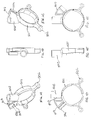
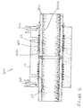
- a fitting in the form of an inline coupler 104 having a hollow body 14 and a socket or tubular opening 16 at each end thereof.
- a grip ring 500 On the end of each socket 16 is provided a grip ring 500.
- the end of the socket is formed with a clamping surface comprising four fingers 52 separated from one another by slots 53.
- the clamping arrangement between cam surfaces defined on the fingers 52 and wedge elements on the grip ring 500 is generally as described in WO2009/010800 .
- the inline coupler is for joining two pipes (not shown) end-to-end, although the principles discussed below apply to any coupler, such as an elbow, T-joint or even a tapping tee.
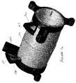
- the coupler 104 has two internal electrofusion elements 22 connected in series to each other and to two terminal pins 24a,b (pins shown in Figure 4 ).
- the terminal pins 24a,b project radially from the body 14.
- Grip rings 500 attach over fingers 52 at both ends of the inline coupler 104.
- Each grip ring 500 comprises an integral upstanding boss or shroud 502 and an integral upstanding terminal pin cover 504.
- Boss and “shroud” are used interchangeably in the following description but the boss/shroud and terminal pin cover each have different functions as will be described below.
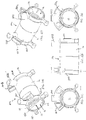
- FIGS 1A - 1F show a grip ring 500 in more detail.
- the grip ring comprises an annular ring section 501 which has wedges on the interior surface thereof for engaging with cam surfaces defined on the fingers as described in WO2009/010800 .
- the integral upstanding boss or shroud 502 is cylindrical and suitably sized so that, when a terminal pin is generally centrally located therein (see Figure 5 ), there is sufficient clearance between the pin and the boss 502 to allow an electrical connector of standard type to be attached to the terminal pin.
- the boss 502 has a slot 503 in a side thereof suitably sized to allow passage of a terminal pin therethrough upon rotation of the grip ring.
- the grip ring further comprises an integral upstanding terminal pin cover 504.
- One side of the terminal pin cover 504 includes an opening large enough to receive a terminal pin moved laterally/axially therein.
- one whole side of the terminal pin cover 504 is open to form the opening 505.
- Opening 505 provides an axial path for the terminal pin when the grip ring 500 is assembled with the hollow body 14 including terminal pins.
- Each grip ring 500 is rotatable about the longitudinal axis of the body between two positions. Firstly, there is an "unclamped” position in which the terminal pin is located under the terminal pin cover 504 and in which the clamping surface does not grip a pipe or spigot placed within the opening 16. Secondly, there is a “clamped” position in which the terminal pin is located within the boss 502 and in which the clamping surface does grip a pipe or spigot placed within opening 16.
- the grip ring rotates through 45 degrees between the two positions and an endstop is provided to prevent further rotation (which would cause the fitting to unclamp again). Clockwise rotation of the grip ring (when looking through the open end of the coupler 104) has two simultaneous effects.
- the first is relative transverse movement of the terminal pin (underneath the terminal pin cover) until it passes through the slot 503 and into the boss 502.
- the second is that the cam surfaces and wedges engage compressing the fingers 52 against the pipe or spigot both securing and centralising it in the socket 104.
- the grip ring 500 comprises lugs on an outer surface to facilitate manual rotation of the grip ring 500.
- the grip ring 500 is shaped to receive a tool, such as a C-Ring style spanner, for mechanically assisting rotation of the grip ring 500.
- the grip ring 500 may not comprise any external features that are specifically for assisting rotation of the grip ring 500.
- the grip ring is provided with axially protruding finger grips 506 to aid the user when rotating the grip ring.
- Other types of finger grips or grip-improving surfaces can be envisaged.
- the uppermost surface 507 of the terminal pin cover provides a "roof" so that the terminal pin remains inaccessible throughout movement of the grip ring from the unclamped position to the clamped position. Only once the terminal pin has arrived in the boss, in the clamped position, is the pin accessible for electrical connection.
- the user in order to connect the power source, the user is required to rotate the grip ring 500 so that the terminal pin is centrally located within the boss 502. In this position, there is sufficient space between the terminal pin 24a/24b and the boss 502 to accommodate the connector from the electrical power source.
- the boss 502 is suitably sized and shaped to permit this, depending upon the expected type of electrical connector.
- the electrofusion elements 22 are composed of a conducting material that produces sufficient heat to melt fusible polymer material when an electrical current is passed through it, but does not itself melt or break.
- the terminal pins 24a, 24b are composed of a good electrically conducting material that does not produce significant heat when an electric current is passed through it.
- the fingers, particularly their proximal root ends 52a are axially positioned relatively close to the electrofusion element 22, in the cold zone of the electrofusion element.
- the proximal root ends 52a would typically be at least 1x, but no more than 3x the wire winding pitch of the electrofusion element from the last turn of wire of the electrofusion element, and in a preferred embodiment would be 1.5x to 2.5x the wire winding pitch. If the proximal root ends 52a are too close to the wire then melting of the support for the clamping fingers 52 may occur.
- each terminal pin is outside the footprint of the grip ring 500, being axially offset therefrom, but the pin can still interact with the terminal pin cover and upstanding boss to control access for electrical connection.
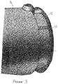
- each socket of the electrofusion coupler 700 comprises an electrofusion element 22 wound in an internal surface thereof.
- Each socket has three zones, namely an inner cold zone 602a, a central hot (or fusion) zone 600, and an outer cold zone 602b.
- the central hot zone 600 is the region around the electrofusion element 22 which is embedded into the internal surface of the coupler 700. When an electric current is supplied to the electrofusion element 22, it will become hot and melt the surrounding plastic.
- the cold zones 602a,b are unheated and in these regions hot melt exudes from the hot, fusion zone 600 during electrofusion. Since the cold zones 602a,b are unheated, the hot melt "freezes off” once it exudes into the cold zones 602a,b, which generates a back pressure into the hot zone 600. The back pressure is required to fill a gap G between a pipe 800 inserted in the socket and the coupler 700, and thereafter to generate pressure to force a weld between the two components.
- the length of the outer cold zone 602b should be of sufficient length to cause freezing of the melt front before it exudes out of the coupling (under normal welding conditions).
- footprint of the grip ring mean the area of the grip ring which overlaps with and is in close sliding contact with the outer surface of the hollow body of the fitting, namely the annular ring portion 501.
Landscapes
- Engineering & Computer Science (AREA)
- Mechanical Engineering (AREA)
- General Engineering & Computer Science (AREA)
- Branch Pipes, Bends, And The Like (AREA)
- Lining Or Joining Of Plastics Or The Like (AREA)
Claims (12)
- Geformte Elektroschweißmuffe (104) zur Verbindung mit einer Kunststoffrohrleitung oder einem Zapfen, die Folgendes umfasst:einen Hohlkörper (14), der mit einer rohrförmigen Öffnung (16) ausgebildet ist, eine Längsachse aufweist und derart ausgelegt ist, dass er ein Ende der Rohrleitung oder des Zapfens, das in Richtung der Achse eingesetzt wird, in engem Gleitsitz an einer Innenfläche der Öffnung aufnimmt;ein Elektroschweißelement (22), das in der Innenfläche in der Öffnung (16) ausgebildet ist;mindestens einen Anschlussstift (24a, 24b), der radial von dem Körper absteht und mit einem Ende des Elektroschweißelements verbunden ist;eine Anschlussstiftabdeckung (504);eine Klemmfläche (52; 53) am Ende der rohrförmigen Öffnung (16);einen Greifring (500), der derart ausgelegt ist, dass er mit der Klemmfläche zusammenpasst; undeinen hochstehenden Vorsprung (502), vorzugsweise einen Hohlzylinder, der radial von dem Greifring (500) absteht, wobei sich bei Drehung des Greifrings der Anschlussstift (24a; 24b) von einer Bedeckung durch die Anschlussstiftabdeckung (504) in eine Aufnahme in dem hochstehenden Vorsprung (502) bewegt, um Zugang zu dem Anschlussstift zur elektrischen Verbindung damit zu ermöglichen;wobei, wenn eine Rohrleitung oder ein Zapfen in die Öffnung eingesetzt und der Greifring (500) um die Achse gedreht wird, der Greifring die Klemmfläche in Eingriff nimmt, wodurch das Rohr von der Klemmfläche gegriffen wird,dadurch gekennzeichnet, dass die Klemmfläche zumindest teilweise in einer kalten Zone (602b) angeordnet ist, die an das Elektroschweißelement angrenzt,und dass die Anschlussstiftabdeckung (504) radial von dem Greifring (500) absteht und derart ausgelegt ist, dass sie den Anschlussstift (24a; 24b) zumindest teilweise abdeckt, um eine Verbindung eines elektrischen Verbinders damit zu verhindern,wobei die Drehung des Greifrings (500) die Anschlussstiftabdeckung (504) so von dem Anschlussstift wegbewegt, dass dem Anschlussstift Zugang zur elektrischen Verbindung damit ermöglicht wird,und dass eine Längsachse der Anschlussstiftabdeckung (504) zu einer Spur des Greifrings (500) axial versetzt ist.
- Muffe nach Anspruch 1, wobei die Klemmfläche Folgendes umfasst:Finger (52) am Ende der Öffnung, die umlaufend um die Öffnung beabstandet sind und dazwischen durch Schlitze (53) voneinander getrennt sind; undNockenflächen, die an den Fingern definiert sind.
- Muffe nach Anspruch 2, wobei der Greifring (500) Keilelemente umfasst, die derart ausgelegt sind, dass sie mit den Nockenflächen an den Fingern zusammenpassen.
- Muffe nach einem der vorangehenden Ansprüche, wobei der Greifring (500) axial auf dem Hohlkörper positionierbar ist, sodass er imstande ist, einen radialen Austritt von Schmelze während des Elektroschweißens im Wesentlichen zu verhindern.
- Muffe nach einem der vorangehenden Ansprüche, wobei während der Drehung des Greifrings (500), bis der Anschlussstift in dem hochstehenden Vorsprung (502) aufgenommen ist, der Anschlussstift für eine elektrische Verbindung damit unzugänglich ist.
- Muffe nach einem der vorangehenden Ansprüche, wobei der Greifring (500) imstande ist, die Klemmfläche (52; 53) nach Drehung um 45 Grad in Eingriff zu nehmen.
- Muffe nach einem der vorangehenden Ansprüche, wobei das Elektroschweißelement (22) vor einem Anschlag endet, der in der Öffnung ausgebildet ist, wobei der Anschlag derart ausgelegt ist, dass er das Einführen der Rohrleitung in die Öffnung begrenzt.
- Muffe nach Anspruch 7, wobei das Elektroschweißelement in der Innenfläche über eine axiale Länge von mindestens 25 % des Abstands vom Ende der Öffnung bis zum Anschlag ausgebildet ist.
- Muffe nach Anspruch 8, wobei das Elektroschweißelement in der Innenfläche über eine axiale Länge von zwischen 55 % und 65 % des Abstands vom Ende der Öffnung bis zum Anschlag ausgebildet ist.
- Muffe nach einem der Ansprüche 7 bis 9, wobei der Abstand vom Ende der Öffnung bis zum Anschlag bis zu 2,5-mal so groß ist wie der Innendurchmesser der Öffnung und vorzugsweise zwischen 0,5- und 2,5-mal so groß ist wie der Innendurchmesser der Öffnung.
- Muffe nach einem der vorangehenden Ansprüche in Abhängigkeit von Anspruch 2, wobei ein Umfangsflansch um die Finger ausgebildet ist, um den Greifring an deren Ende zu halten.
- Inline-Verbindungsstück (104), umfassend einen Hohlkörper, der eine Muffe nach einem der vorangehenden Ansprüche an jedem seiner Enden aufweist.
Applications Claiming Priority (1)
| Application Number | Priority Date | Filing Date | Title |
|---|---|---|---|
| GB1115443.2A GB2494423B (en) | 2011-09-07 | 2011-09-07 | Electrofusion fitting |
Publications (2)
| Publication Number | Publication Date |
|---|---|
| EP2617552A1 EP2617552A1 (de) | 2013-07-24 |
| EP2617552B1 true EP2617552B1 (de) | 2016-11-30 |
Family
ID=44908194
Family Applications (1)
| Application Number | Title | Priority Date | Filing Date |
|---|---|---|---|
| EP12180932.1A Not-in-force EP2617552B1 (de) | 2011-09-07 | 2012-08-17 | Elektroschweißmuffe |
Country Status (2)
| Country | Link |
|---|---|
| EP (1) | EP2617552B1 (de) |
| GB (1) | GB2494423B (de) |
Families Citing this family (4)
| Publication number | Priority date | Publication date | Assignee | Title |
|---|---|---|---|---|
| ES2581377B1 (es) * | 2016-05-13 | 2017-05-30 | Abn Pipe Systems, S.L.U. | Dispositivo de conexión para elementos de tubería |
| JP6921588B2 (ja) * | 2017-03-31 | 2021-08-18 | 積水化学工業株式会社 | 樹脂管同士の仮固定構造 |
| CN109808130A (zh) * | 2019-02-02 | 2019-05-28 | 江苏云皓塑料管件有限公司 | 电熔管件模芯自动绕丝脱模机 |
| CN113635258B (zh) * | 2021-08-15 | 2024-08-13 | 江西铜业集团(贵溪)防腐工程有限公司 | 一种电熔管道压装工具 |
Family Cites Families (8)
| Publication number | Priority date | Publication date | Assignee | Title |
|---|---|---|---|---|
| US4508368A (en) * | 1982-03-01 | 1985-04-02 | R & G Sloane Mfg. Co., Inc. | Plastic pipe joint |
| CH671444A5 (de) * | 1986-06-25 | 1989-08-31 | Fischer Ag Georg | |
| FR2648077B1 (fr) * | 1989-06-09 | 1991-10-18 | Boulet D Auria Terlizzi | Procede de raccordement de deux elements tubulaires en matiere plastique par electro-soudage et raccord d'electro-soudage pour la mise en oeuvre de ce procede |
| CH685403A5 (de) | 1991-07-22 | 1995-06-30 | Fischer Georg Rohrleitung | Formteil aus thermoplastischem Material. |
| JPH06300177A (ja) * | 1993-04-08 | 1994-10-28 | Hitachi Metals Ltd | パイプクランプ付電気融着継手 |
| DE4437407A1 (de) * | 1994-10-19 | 1996-04-25 | Gruber Alois Agru Gmbh | Schweißmuffe zum Verbinden von Kunststoffrohrteilen |
| JPH10274380A (ja) * | 1997-03-31 | 1998-10-13 | Hitachi Metals Ltd | 電気融着継手 |
| GB2451081B (en) | 2007-07-17 | 2009-09-09 | Uponor Innovation Ab | Electrofusion fitting |
-
2011
- 2011-09-07 GB GB1115443.2A patent/GB2494423B/en active Active
-
2012
- 2012-08-17 EP EP12180932.1A patent/EP2617552B1/de not_active Not-in-force
Non-Patent Citations (1)
| Title |
|---|
| None * |
Also Published As
| Publication number | Publication date |
|---|---|
| GB2494423A (en) | 2013-03-13 |
| GB2494423B (en) | 2016-07-13 |
| GB201115443D0 (en) | 2011-10-26 |
| EP2617552A1 (de) | 2013-07-24 |
Similar Documents
| Publication | Publication Date | Title |
|---|---|---|
| EP2178691B1 (de) | Elektroschweissmuffe | |
| US6131954A (en) | Weldable couple for electrofusion coupling of profile wall thermoplastic pipes without a separate coupler | |
| EP2617552B1 (de) | Elektroschweißmuffe | |
| US20100295299A1 (en) | Joint and joining method for plastic pipe | |
| WO2015132783A2 (en) | Electromagnetic induction welding of fluid distribution systems | |
| CZ20023283A3 (cs) | Zařízení na spojování součástí z tavitelných plastů | |
| CN103180652B (zh) | 多层管道的联接件、焊接装置、联接方法及其所得组件 | |
| EP1214545B1 (de) | Verbesserte schweissmuffe | |
| US6521072B1 (en) | Method of coupling profile wall thermoplastic pipes | |
| EP3225896B1 (de) | Elektroschweissbarer sattelförmiger rohrverbinder und entsprechendes schweissverfahren | |
| JP2009204144A (ja) | ホースと口金具用樹脂製ニップルとの接続方法及びホース口金具接続構造 | |
| RU2650225C2 (ru) | Армирующая муфта для соединителя, узел армирующей муфты и соединителя, способ сварки, например, многослойных трубопроводов и узла | |
| JP5400367B2 (ja) | 電気融着継手 | |
| JP2011117563A (ja) | 電気融着継手 | |
| EP2926978B1 (de) | Zwischenschweißvorrichtung | |
| WO1995015253A1 (en) | Joining of hollow elongate members | |
| WO2023054699A1 (ja) | 配管部材及び配管部材の製造方法 | |
| JP5173571B2 (ja) | エレクトロフュージョン継手 | |
| HK1137967B (en) | Electrofusion fitting | |
| JP2018173147A (ja) | 樹脂管同士の仮固定構造 | |
| JP5839565B2 (ja) | 電気融着継手用接続金具及び接続金具付き電気融着継手 | |
| JP5976457B2 (ja) | 被覆管路、その施工方法、およびカバー | |
| JP4268279B2 (ja) | 溶着継手 | |
| JP2003176897A (ja) | 樹脂製ヘッダー及びそれを用いたヘッダー工法 | |
| JP2005321050A (ja) | 電気融着自在継手 |
Legal Events
| Date | Code | Title | Description |
|---|---|---|---|
| PUAI | Public reference made under article 153(3) epc to a published international application that has entered the european phase |
Free format text: ORIGINAL CODE: 0009012 |
|
| AK | Designated contracting states |
Kind code of ref document: A1 Designated state(s): AL AT BE BG CH CY CZ DE DK EE ES FI FR GB GR HR HU IE IS IT LI LT LU LV MC MK MT NL NO PL PT RO RS SE SI SK SM TR |
|
| AX | Request for extension of the european patent |
Extension state: BA ME |
|
| 17P | Request for examination filed |
Effective date: 20131106 |
|
| RBV | Designated contracting states (corrected) |
Designated state(s): AL AT BE BG CH CY CZ DE DK EE ES FI FR GB GR HR HU IE IS IT LI LT LU LV MC MK MT NL NO PL PT RO RS SE SI SK SM TR |
|
| 17Q | First examination report despatched |
Effective date: 20140320 |
|
| GRAP | Despatch of communication of intention to grant a patent |
Free format text: ORIGINAL CODE: EPIDOSNIGR1 |
|
| INTG | Intention to grant announced |
Effective date: 20160628 |
|
| GRAS | Grant fee paid |
Free format text: ORIGINAL CODE: EPIDOSNIGR3 |
|
| GRAA | (expected) grant |
Free format text: ORIGINAL CODE: 0009210 |
|
| AK | Designated contracting states |
Kind code of ref document: B1 Designated state(s): AL AT BE BG CH CY CZ DE DK EE ES FI FR GB GR HR HU IE IS IT LI LT LU LV MC MK MT NL NO PL PT RO RS SE SI SK SM TR |
|
| REG | Reference to a national code |
Ref country code: CH Ref legal event code: EP Ref country code: GB Ref legal event code: FG4D |
|
| REG | Reference to a national code |
Ref country code: AT Ref legal event code: REF Ref document number: 849381 Country of ref document: AT Kind code of ref document: T Effective date: 20161215 |
|
| REG | Reference to a national code |
Ref country code: IE Ref legal event code: FG4D |
|
| REG | Reference to a national code |
Ref country code: DE Ref legal event code: R096 Ref document number: 602012025955 Country of ref document: DE |
|
| PG25 | Lapsed in a contracting state [announced via postgrant information from national office to epo] |
Ref country code: LV Free format text: LAPSE BECAUSE OF FAILURE TO SUBMIT A TRANSLATION OF THE DESCRIPTION OR TO PAY THE FEE WITHIN THE PRESCRIBED TIME-LIMIT Effective date: 20161130 |
|
| REG | Reference to a national code |
Ref country code: CH Ref legal event code: NV Representative=s name: MICHELI AND CIE SA, CH |
|
| REG | Reference to a national code |
Ref country code: LT Ref legal event code: MG4D |
|
| REG | Reference to a national code |
Ref country code: NL Ref legal event code: MP Effective date: 20161130 |
|
| REG | Reference to a national code |
Ref country code: AT Ref legal event code: MK05 Ref document number: 849381 Country of ref document: AT Kind code of ref document: T Effective date: 20161130 |
|
| PG25 | Lapsed in a contracting state [announced via postgrant information from national office to epo] |
Ref country code: GR Free format text: LAPSE BECAUSE OF FAILURE TO SUBMIT A TRANSLATION OF THE DESCRIPTION OR TO PAY THE FEE WITHIN THE PRESCRIBED TIME-LIMIT Effective date: 20170301 Ref country code: NO Free format text: LAPSE BECAUSE OF FAILURE TO SUBMIT A TRANSLATION OF THE DESCRIPTION OR TO PAY THE FEE WITHIN THE PRESCRIBED TIME-LIMIT Effective date: 20170228 Ref country code: LT Free format text: LAPSE BECAUSE OF FAILURE TO SUBMIT A TRANSLATION OF THE DESCRIPTION OR TO PAY THE FEE WITHIN THE PRESCRIBED TIME-LIMIT Effective date: 20161130 Ref country code: SE Free format text: LAPSE BECAUSE OF FAILURE TO SUBMIT A TRANSLATION OF THE DESCRIPTION OR TO PAY THE FEE WITHIN THE PRESCRIBED TIME-LIMIT Effective date: 20161130 |
|
| PG25 | Lapsed in a contracting state [announced via postgrant information from national office to epo] |
Ref country code: PL Free format text: LAPSE BECAUSE OF FAILURE TO SUBMIT A TRANSLATION OF THE DESCRIPTION OR TO PAY THE FEE WITHIN THE PRESCRIBED TIME-LIMIT Effective date: 20161130 Ref country code: AT Free format text: LAPSE BECAUSE OF FAILURE TO SUBMIT A TRANSLATION OF THE DESCRIPTION OR TO PAY THE FEE WITHIN THE PRESCRIBED TIME-LIMIT Effective date: 20161130 Ref country code: ES Free format text: LAPSE BECAUSE OF FAILURE TO SUBMIT A TRANSLATION OF THE DESCRIPTION OR TO PAY THE FEE WITHIN THE PRESCRIBED TIME-LIMIT Effective date: 20161130 Ref country code: HR Free format text: LAPSE BECAUSE OF FAILURE TO SUBMIT A TRANSLATION OF THE DESCRIPTION OR TO PAY THE FEE WITHIN THE PRESCRIBED TIME-LIMIT Effective date: 20161130 Ref country code: FI Free format text: LAPSE BECAUSE OF FAILURE TO SUBMIT A TRANSLATION OF THE DESCRIPTION OR TO PAY THE FEE WITHIN THE PRESCRIBED TIME-LIMIT Effective date: 20161130 Ref country code: PT Free format text: LAPSE BECAUSE OF FAILURE TO SUBMIT A TRANSLATION OF THE DESCRIPTION OR TO PAY THE FEE WITHIN THE PRESCRIBED TIME-LIMIT Effective date: 20170330 Ref country code: RS Free format text: LAPSE BECAUSE OF FAILURE TO SUBMIT A TRANSLATION OF THE DESCRIPTION OR TO PAY THE FEE WITHIN THE PRESCRIBED TIME-LIMIT Effective date: 20161130 |
|
| PG25 | Lapsed in a contracting state [announced via postgrant information from national office to epo] |
Ref country code: NL Free format text: LAPSE BECAUSE OF FAILURE TO SUBMIT A TRANSLATION OF THE DESCRIPTION OR TO PAY THE FEE WITHIN THE PRESCRIBED TIME-LIMIT Effective date: 20161130 |
|
| PG25 | Lapsed in a contracting state [announced via postgrant information from national office to epo] |
Ref country code: CZ Free format text: LAPSE BECAUSE OF FAILURE TO SUBMIT A TRANSLATION OF THE DESCRIPTION OR TO PAY THE FEE WITHIN THE PRESCRIBED TIME-LIMIT Effective date: 20161130 Ref country code: RO Free format text: LAPSE BECAUSE OF FAILURE TO SUBMIT A TRANSLATION OF THE DESCRIPTION OR TO PAY THE FEE WITHIN THE PRESCRIBED TIME-LIMIT Effective date: 20161130 Ref country code: DK Free format text: LAPSE BECAUSE OF FAILURE TO SUBMIT A TRANSLATION OF THE DESCRIPTION OR TO PAY THE FEE WITHIN THE PRESCRIBED TIME-LIMIT Effective date: 20161130 Ref country code: SK Free format text: LAPSE BECAUSE OF FAILURE TO SUBMIT A TRANSLATION OF THE DESCRIPTION OR TO PAY THE FEE WITHIN THE PRESCRIBED TIME-LIMIT Effective date: 20161130 Ref country code: EE Free format text: LAPSE BECAUSE OF FAILURE TO SUBMIT A TRANSLATION OF THE DESCRIPTION OR TO PAY THE FEE WITHIN THE PRESCRIBED TIME-LIMIT Effective date: 20161130 |
|
| PG25 | Lapsed in a contracting state [announced via postgrant information from national office to epo] |
Ref country code: BG Free format text: LAPSE BECAUSE OF FAILURE TO SUBMIT A TRANSLATION OF THE DESCRIPTION OR TO PAY THE FEE WITHIN THE PRESCRIBED TIME-LIMIT Effective date: 20170228 Ref country code: BE Free format text: LAPSE BECAUSE OF FAILURE TO SUBMIT A TRANSLATION OF THE DESCRIPTION OR TO PAY THE FEE WITHIN THE PRESCRIBED TIME-LIMIT Effective date: 20161130 Ref country code: IT Free format text: LAPSE BECAUSE OF FAILURE TO SUBMIT A TRANSLATION OF THE DESCRIPTION OR TO PAY THE FEE WITHIN THE PRESCRIBED TIME-LIMIT Effective date: 20161130 Ref country code: SM Free format text: LAPSE BECAUSE OF FAILURE TO SUBMIT A TRANSLATION OF THE DESCRIPTION OR TO PAY THE FEE WITHIN THE PRESCRIBED TIME-LIMIT Effective date: 20161130 |
|
| REG | Reference to a national code |
Ref country code: DE Ref legal event code: R097 Ref document number: 602012025955 Country of ref document: DE |
|
| PLBE | No opposition filed within time limit |
Free format text: ORIGINAL CODE: 0009261 |
|
| STAA | Information on the status of an ep patent application or granted ep patent |
Free format text: STATUS: NO OPPOSITION FILED WITHIN TIME LIMIT |
|
| PGFP | Annual fee paid to national office [announced via postgrant information from national office to epo] |
Ref country code: GB Payment date: 20170822 Year of fee payment: 6 Ref country code: CH Payment date: 20170821 Year of fee payment: 6 Ref country code: DE Payment date: 20170822 Year of fee payment: 6 |
|
| 26N | No opposition filed |
Effective date: 20170831 |
|
| PG25 | Lapsed in a contracting state [announced via postgrant information from national office to epo] |
Ref country code: SI Free format text: LAPSE BECAUSE OF FAILURE TO SUBMIT A TRANSLATION OF THE DESCRIPTION OR TO PAY THE FEE WITHIN THE PRESCRIBED TIME-LIMIT Effective date: 20161130 |
|
| PG25 | Lapsed in a contracting state [announced via postgrant information from national office to epo] |
Ref country code: MC Free format text: LAPSE BECAUSE OF FAILURE TO SUBMIT A TRANSLATION OF THE DESCRIPTION OR TO PAY THE FEE WITHIN THE PRESCRIBED TIME-LIMIT Effective date: 20161130 |
|
| REG | Reference to a national code |
Ref country code: FR Ref legal event code: ST Effective date: 20180430 |
|
| REG | Reference to a national code |
Ref country code: IE Ref legal event code: MM4A |
|
| PG25 | Lapsed in a contracting state [announced via postgrant information from national office to epo] |
Ref country code: LU Free format text: LAPSE BECAUSE OF NON-PAYMENT OF DUE FEES Effective date: 20170817 |
|
| PG25 | Lapsed in a contracting state [announced via postgrant information from national office to epo] |
Ref country code: IE Free format text: LAPSE BECAUSE OF NON-PAYMENT OF DUE FEES Effective date: 20170817 |
|
| PG25 | Lapsed in a contracting state [announced via postgrant information from national office to epo] |
Ref country code: FR Free format text: LAPSE BECAUSE OF NON-PAYMENT OF DUE FEES Effective date: 20170831 |
|
| PG25 | Lapsed in a contracting state [announced via postgrant information from national office to epo] |
Ref country code: MT Free format text: LAPSE BECAUSE OF NON-PAYMENT OF DUE FEES Effective date: 20170817 |
|
| REG | Reference to a national code |
Ref country code: DE Ref legal event code: R119 Ref document number: 602012025955 Country of ref document: DE |
|
| REG | Reference to a national code |
Ref country code: CH Ref legal event code: PL |
|
| GBPC | Gb: european patent ceased through non-payment of renewal fee |
Effective date: 20180817 |
|
| PG25 | Lapsed in a contracting state [announced via postgrant information from national office to epo] |
Ref country code: CH Free format text: LAPSE BECAUSE OF NON-PAYMENT OF DUE FEES Effective date: 20180831 Ref country code: LI Free format text: LAPSE BECAUSE OF NON-PAYMENT OF DUE FEES Effective date: 20180831 |
|
| PG25 | Lapsed in a contracting state [announced via postgrant information from national office to epo] |
Ref country code: HU Free format text: LAPSE BECAUSE OF FAILURE TO SUBMIT A TRANSLATION OF THE DESCRIPTION OR TO PAY THE FEE WITHIN THE PRESCRIBED TIME-LIMIT; INVALID AB INITIO Effective date: 20120817 |
|
| PG25 | Lapsed in a contracting state [announced via postgrant information from national office to epo] |
Ref country code: DE Free format text: LAPSE BECAUSE OF NON-PAYMENT OF DUE FEES Effective date: 20190301 |
|
| PG25 | Lapsed in a contracting state [announced via postgrant information from national office to epo] |
Ref country code: CY Free format text: LAPSE BECAUSE OF NON-PAYMENT OF DUE FEES Effective date: 20161130 Ref country code: GB Free format text: LAPSE BECAUSE OF NON-PAYMENT OF DUE FEES Effective date: 20180817 |
|
| PG25 | Lapsed in a contracting state [announced via postgrant information from national office to epo] |
Ref country code: MK Free format text: LAPSE BECAUSE OF FAILURE TO SUBMIT A TRANSLATION OF THE DESCRIPTION OR TO PAY THE FEE WITHIN THE PRESCRIBED TIME-LIMIT Effective date: 20161130 |
|
| PG25 | Lapsed in a contracting state [announced via postgrant information from national office to epo] |
Ref country code: TR Free format text: LAPSE BECAUSE OF FAILURE TO SUBMIT A TRANSLATION OF THE DESCRIPTION OR TO PAY THE FEE WITHIN THE PRESCRIBED TIME-LIMIT Effective date: 20161130 |
|
| PG25 | Lapsed in a contracting state [announced via postgrant information from national office to epo] |
Ref country code: AL Free format text: LAPSE BECAUSE OF FAILURE TO SUBMIT A TRANSLATION OF THE DESCRIPTION OR TO PAY THE FEE WITHIN THE PRESCRIBED TIME-LIMIT Effective date: 20161130 Ref country code: IS Free format text: LAPSE BECAUSE OF FAILURE TO SUBMIT A TRANSLATION OF THE DESCRIPTION OR TO PAY THE FEE WITHIN THE PRESCRIBED TIME-LIMIT Effective date: 20170330 |