EP2617143B1 - Coded light emitting device - Google Patents
Coded light emitting device Download PDFInfo
- Publication number
- EP2617143B1 EP2617143B1 EP11764324.7A EP11764324A EP2617143B1 EP 2617143 B1 EP2617143 B1 EP 2617143B1 EP 11764324 A EP11764324 A EP 11764324A EP 2617143 B1 EP2617143 B1 EP 2617143B1
- Authority
- EP
- European Patent Office
- Prior art keywords
- segment
- led
- common electrode
- data
- light emitting
- Prior art date
- Legal status (The legal status is an assumption and is not a legal conclusion. Google has not performed a legal analysis and makes no representation as to the accuracy of the status listed.)
- Not-in-force
Links
Images


Classifications
-
- H—ELECTRICITY
- H04—ELECTRIC COMMUNICATION TECHNIQUE
- H04B—TRANSMISSION
- H04B10/00—Transmission systems employing electromagnetic waves other than radio-waves, e.g. infrared, visible or ultraviolet light, or employing corpuscular radiation, e.g. quantum communication
- H04B10/11—Arrangements specific to free-space transmission, i.e. transmission through air or vacuum
- H04B10/114—Indoor or close-range type systems
- H04B10/116—Visible light communication
-
- H—ELECTRICITY
- H04—ELECTRIC COMMUNICATION TECHNIQUE
- H04B—TRANSMISSION
- H04B10/00—Transmission systems employing electromagnetic waves other than radio-waves, e.g. infrared, visible or ultraviolet light, or employing corpuscular radiation, e.g. quantum communication
- H04B10/11—Arrangements specific to free-space transmission, i.e. transmission through air or vacuum
- H04B10/114—Indoor or close-range type systems
- H04B10/1141—One-way transmission
-
- H—ELECTRICITY
- H05—ELECTRIC TECHNIQUES NOT OTHERWISE PROVIDED FOR
- H05B—ELECTRIC HEATING; ELECTRIC LIGHT SOURCES NOT OTHERWISE PROVIDED FOR; CIRCUIT ARRANGEMENTS FOR ELECTRIC LIGHT SOURCES, IN GENERAL
- H05B45/00—Circuit arrangements for operating light-emitting diodes [LED]
- H05B45/30—Driver circuits
- H05B45/395—Linear regulators
-
- H—ELECTRICITY
- H05—ELECTRIC TECHNIQUES NOT OTHERWISE PROVIDED FOR
- H05B—ELECTRIC HEATING; ELECTRIC LIGHT SOURCES NOT OTHERWISE PROVIDED FOR; CIRCUIT ARRANGEMENTS FOR ELECTRIC LIGHT SOURCES, IN GENERAL
- H05B45/00—Circuit arrangements for operating light-emitting diodes [LED]
-
- Y—GENERAL TAGGING OF NEW TECHNOLOGICAL DEVELOPMENTS; GENERAL TAGGING OF CROSS-SECTIONAL TECHNOLOGIES SPANNING OVER SEVERAL SECTIONS OF THE IPC; TECHNICAL SUBJECTS COVERED BY FORMER USPC CROSS-REFERENCE ART COLLECTIONS [XRACs] AND DIGESTS
- Y02—TECHNOLOGIES OR APPLICATIONS FOR MITIGATION OR ADAPTATION AGAINST CLIMATE CHANGE
- Y02B—CLIMATE CHANGE MITIGATION TECHNOLOGIES RELATED TO BUILDINGS, e.g. HOUSING, HOUSE APPLIANCES OR RELATED END-USER APPLICATIONS
- Y02B20/00—Energy efficient lighting technologies, e.g. halogen lamps or gas discharge lamps
- Y02B20/30—Semiconductor lamps, e.g. solid state lamps [SSL] light emitting diodes [LED] or organic LED [OLED]
Definitions
- Embodiments of the present invention relate generally to the field of illumination systems, and, more specifically, to systems and methods for embedding data into the light output of such illumination systems.
- Visible light communications refer to communicating data via the light output produced by lighting sources. Such communications is a promising way of enabling localized wireless data exchange in the future because a wide unlicensed frequency band is available for this and because light emitting diodes (LEDs) used to illuminate a room or a space can be applied to provide the communications. Possibly every lighting source of the future could become a communications source.
- LEDs light emitting diodes
- One visible light communications technique is based on embedding data into the light output of an illumination device by modulating the light output of the illumination device in response to a data signal (such light output is sometimes referred to as “coded light” and abbreviated as "CL”).
- a data signal such light output is sometimes referred to as “coded light” and abbreviated as "CL”
- the light output is modulated at a high frequency and/or using a special modulation scheme so that the modulation is invisible to human beings.
- illumination systems usually employ dedicated driver electronics to allow superimposing a data signal onto the LED driving signal.
- Figure 1 is a schematic illustration of such an illumination system 100.
- the illumination system 100 includes a dedicated driver circuit 110 and a LED 120, and is configured to generate a light output 125 according to light settings.
- the dedicated driver circuit 110 includes a drive signal generator 112 and a driver controller 114.
- the illumination system 100 is configured to operate as follows. As shown in Figure 1 , the light settings for the illumination system 100 are provided to the drive signal generator 112. The light settings indicate what the average light output 125 should be in terms, for example, of light power, e.g. defined in lumen, and color.
- the drive signal generator 112 translates the light settings into a drive signal (e.g., a drive current) for the LED 120 and provides the drive signal to the driver controller 114.
- a drive signal e.g., a drive current
- the driver controller 114 is further configured to receive a signal 135 from a data source 130.
- the signal 135 includes data bits to be embedded into the light output 125 of the LED 120.
- the driver controller 114 is configured to modulate the drive signal to be applied to the LED 120 in response to the signal 135 in order to embed the data bits of the signal 135 into the light output 125.
- Various techniques how the drive signal could be modulated in order to embed data into the light output of a light source are known to people skilled in the art (pulse width modulation, amplitude modulation, etc) and, therefore, are not described in further detail.
- an illumination device for embedding one or more data symbols of a data signal into a luminance output of the illumination device.
- the illumination device includes a LED comprising at least a first segment and a second segment.
- the first segment and the second segment have a common electrode and are individually controllable.
- the LED is configured to generate the luminance output in response to a drive signal.
- the illumination device further includes a controller configured for switching the second segment on or off in response to the data signal to embed the one or more data symbols of the data signal.
- the phrase “switch off a segment” [of a LED] refers to disrupting the drive signal provided to the segment.
- the phrase “switch on a segment” [of a LED] refers to providing the drive signal to the segment. When a segment is switched off it does not generate light. When a segment is switched on, it generates light.
- the luminance output of the LED is a composition of the luminance outputs of each of the segments.
- the present invention is based on the recognition that providing a LED separated into at least two segments having a common electrode and which are individually controllable (i.e. they can be individually switched on or off) allows varying the light output produced by the LED without having to change the drive signal supplied to the common electrode of the segments.
- a drive signal is applied to the common electrode, switching off one of the segments results in the increase of the current density through the other segment which, at nominal operation, produces a degradation of the light output performance because the internal quantum efficiency (IQE) of the LED drops (this effect is commonly known as the "droop effect").
- IQE internal quantum efficiency
- variations in the light output performance may be used to embed data symbols.
- a conventional LED driver may be used to provide a drive signal to the common electrode of the two segments, while modulation of the light output is performed by switching one of the segments on and off using e.g. switches which are external to the LED driver.
- This approach provides an advantage over the prior art in that such a device is compatible with conventional LED drivers since no additional electronics for modulating the drive signal are necessary, which enables simple implementation and reduced costs.
- the term "nominal operation" is used to describe operation of a LED at such current density that desirably results in the maximum IQE of the LED.
- the light sources described herein may comprise inorganic or organic light emitting diodes.
- Data embedded in the light output of the illumination system may comprise localized identification information of the light sources, their capabilities and/or settings, or other types of information related to the light sources.
- the illumination system is not necessarily applied for the purpose of illuminating a space or area but may also be applied for data communication as such.
- the illumination system may constitute an access point to a network.
- at least part of the light output produced by the illumination system may lie outside of the visible spectrum (i.e., the light output of one of the light sources of the system may lie outside of the visible spectrum).
- a corresponding method for embedding one or more data symbols of a data signal into a luminance output of an illumination device as well as an illumination system comprising one or more illumination devices are provided.
- Claim 1 provides two ways to define a modulation depth for the illumination device.
- modulation depth refers to a range of variation in the amplitude or intensity of the luminance output of the LED, where different levels in the amplitude or intensity correspond to different data bits encoded in the luminance output.
- Embodiments specify that the common electrode could be a cathode or an anode and/or provide an advantageous type of the LED to be employed in the illumination device.
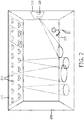
- Figure 2 shows a structure 200 - in this case a room - with an installed illumination system 210.
- the illumination system 210 comprises one or more of light sources 220 and one or more controllers (not shown in Figure 1 ) controlling the light sources 220. When driven with an electrical signal, the light sources 220 illuminate parts of the structure 200.
- the light sources 220 may comprise inorganic and/or organic light emitting devices.
- the illumination system 210 may further comprise a remote control 230 allowing a user to control the light sources 220.
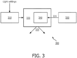
- FIG 3 is a schematic illustration of an illumination system 300 according to one embodiment of the present invention.
- the illumination system 300 may be used as the illumination system 210 in the structure 200 illustrated in Figure 2 .
- the illumination system 300 includes a LED 320 which includes at least two individually controllable segments having a common electrode, a LED driver 310 configured to provide a drive signal to the LED 320, and a data source 330 configured to provide data to be embedded into the light output of the LED 320.
- the illumination system 300 is configured to operate as follows. As shown in Figure 3 , the light settings for the illumination system 300 are provided to the LED driver 310.
- the light settings may be e.g. provided by a user via the remote control 230 or may be preprogrammed and provided from an external unit controlling the scene setting. Alternatively, the light settings may be preprogrammed and stored in a memory within the LED driver 310 or within the illumination system 300.
- the LED driver 310 translates the light settings into a drive signal for the LED 320.
- the LED driver 310 comprises a current source providing the drive signal in the form of a drive current.
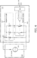
- the LED 320 may be implemented as illustrated in Figure 4 .
- the LED 320 includes an emitting portion 422 and a switching portion 424.
- the emitting portion 422 is manufactured in such a way that n portions of the LED chip area can be partially isolated from the others, resulting in n segments, shown as D1, D2, .. Dn, each of which is configured to emit light in response to the drive current.
- n denotes any integer number equal or greater than 2.
- the segments D1, D2, .. Dn have a common electrode.
- the common electrode is shown to be an anode 426, but, in other embodiments and with modifications to the circuit that will be apparent to the person skilled in the art, the common electrode could be a cathode.
- the switching portion 424 includes (n-1) switches, shown in Figure 4 as S2, ... Sn, where each of the switches S2, ... Sn is used to switch on or off a corresponding segment D2, ... Dn of the emitting portion 422.
- a switch S2 corresponds to a segment D2
- a switch S3 corresponds to a segment D3, and so on.
- Idrv a constant drive current
- the currents going through each of the segments shown in Figure 4 as currents I1, I2, ... In, cause the segments to emit light.
- the sum of light contributions from each emitting segment comprises the luminance output of the LED 320.
- the phrase “constant drive signal” (which includes “constant drive current”) is used to reflect the fact that the drive signal is not modulated to embed data bits. This does not exclude drive signals consisting of pulses, as long as the pulses are not modulated to embed data signals, as was done in the prior art.
- the LED 320 further includes a controller 340.
- the controller 340 is configured to receive a data signal 335 from a data source 330.
- the signal 335 includes (at least) data bits to be embedded into the light output 325 of the LED 320.
- the symbols are referred to as bits. However, it should be recognized that whenever the word "bit" is used in the present application, a wider definition of a "symbol” applies which may also comprise multiple bits represented by a single symbol. For instance multi-level symbols, where not only 0 and 1 exist to embed data, but multiple discrete levels are defined to represent data.
- the controller 340 is configured to switch segments D2, ... Dn on or off in response to the signal 335 in order to embed the data bits of the signal 335 into the light output 325.
- the amount of emitting area corresponding to each of the different segments defines the intensity levels of the light output modulation.
- the number of segments that can be switched on or off defines the number of modulation levels. For example, for a two level modulation (i.e. each bit to be embedded is either "1" or "0"), only two segments within the LED 320 are required - one segment which is always switched on and another segment which could be switched on or off to embed data bits. Referring to Figure 4 , such an embodiment corresponds to the emitting portion 422 comprising only two emitting segments, D1 and D2.
- the size of the segment D2 may be made to be approximately 10% of the total area of the emitting portion 422 and to embed a binary value of "0" from the signal 335, the controller 340 would switch segment D2 off (i.e., open the corresponding switch S2 ).
- the emitting portion 422 comprises the segments D1 ... Dn.
- n is an integer between 3 and 10, more preferably between 5 and 8, such as 6 or 7. Switching the segments D2 ... Dn using the switches S2 ... Sn enables implementing data with multiple discrete levels in the light output 325 of LED 320.
- the relative sizes A2 ... An of the segments D2 ... Dn are all equal.
- the segments D2 ... Dn are designed such that their nominal operation current densities relate to each other similarly as described for the sizes above.
- the LED 320 could also operate in DC mode as any other conventional LED device when switches S2-Sn remain in on-state. Namely, the current through the segments D1, D2, ... Dn will flow uniformly provided that the on-resistance of the switches S2, ... Sn is much lower than the dynamic resistance of the segments.
- the LED driver 310 may comprise a voltage source providing the drive signal in the form of a drive voltage.
- a voltage source providing the drive signal in the form of a drive voltage.
- One advantage of the present invention is that the drive signal provided by the LED driver to the LED does not need to be modulated to embed the data symbols because the data symbols are embedded via switching of the individual segments of the LED.
- conventional LED drivers may be employed, eliminating the need to include complicated and costly electronics capable of modulating the drive signal.
Landscapes
- Physics & Mathematics (AREA)
- Electromagnetism (AREA)
- Engineering & Computer Science (AREA)
- Computer Networks & Wireless Communication (AREA)
- Signal Processing (AREA)
- Circuit Arrangement For Electric Light Sources In General (AREA)
- Optical Communication System (AREA)
- Led Devices (AREA)
- Led Device Packages (AREA)
Priority Applications (1)
| Application Number | Priority Date | Filing Date | Title |
|---|---|---|---|
| EP11764324.7A EP2617143B1 (en) | 2010-09-14 | 2011-09-08 | Coded light emitting device |
Applications Claiming Priority (3)
| Application Number | Priority Date | Filing Date | Title |
|---|---|---|---|
| EP10176587 | 2010-09-14 | ||
| EP11764324.7A EP2617143B1 (en) | 2010-09-14 | 2011-09-08 | Coded light emitting device |
| PCT/IB2011/053924 WO2012035469A1 (en) | 2010-09-14 | 2011-09-08 | Coded light emitting device |
Publications (2)
| Publication Number | Publication Date |
|---|---|
| EP2617143A1 EP2617143A1 (en) | 2013-07-24 |
| EP2617143B1 true EP2617143B1 (en) | 2017-11-15 |
Family
ID=44735992
Family Applications (1)
| Application Number | Title | Priority Date | Filing Date |
|---|---|---|---|
| EP11764324.7A Not-in-force EP2617143B1 (en) | 2010-09-14 | 2011-09-08 | Coded light emitting device |
Country Status (8)
| Country | Link |
|---|---|
| US (1) | US9686011B2 (enExample) |
| EP (1) | EP2617143B1 (enExample) |
| JP (1) | JP5952820B2 (enExample) |
| CN (1) | CN103098553B (enExample) |
| BR (1) | BR112013005767A2 (enExample) |
| RU (1) | RU2613430C2 (enExample) |
| TW (1) | TW201225548A (enExample) |
| WO (1) | WO2012035469A1 (enExample) |
Families Citing this family (18)
| Publication number | Priority date | Publication date | Assignee | Title |
|---|---|---|---|---|
| JP6021003B2 (ja) * | 2012-11-05 | 2016-11-02 | パナソニックIpマネジメント株式会社 | 可視光通信用照明器具 |
| WO2014080321A1 (en) | 2012-11-26 | 2014-05-30 | Koninklijke Philips N.V. | System and method for remote control of electrical appliance using reflected light |
| CN104995998B (zh) | 2013-02-19 | 2018-01-09 | 飞利浦灯具控股公司 | 用于控制照明的方法和装置 |
| US9210769B2 (en) * | 2013-03-15 | 2015-12-08 | Microchip Technology Incorporated | Constant brightness LED drive communications port |
| US9407367B2 (en) * | 2013-04-25 | 2016-08-02 | Beijing Guo Cheng Wan Tong Information Co. Ltd | Methods and devices for transmitting/obtaining information by visible light signals |
| CN104348761A (zh) * | 2013-07-30 | 2015-02-11 | 北京千橡网景科技发展有限公司 | 信号的编解码方法 |
| CN103795465B (zh) * | 2013-07-31 | 2015-04-15 | 深圳光启创新技术有限公司 | 基于多阶幅度调制的可见光信号的编码和解码方法、装置及系统 |
| CN103795487B (zh) * | 2013-09-30 | 2015-03-11 | 深圳光启创新技术有限公司 | 可见光信号发送、接收处理方法、发射端、接收端及系统 |
| CN103701526B (zh) * | 2013-12-09 | 2016-01-20 | 西安理工大学 | 可见光通信中的多维编码方法 |
| JP6485767B2 (ja) * | 2014-12-26 | 2019-03-20 | パナソニックIpマネジメント株式会社 | 照明器具及び可視光通信システム |
| CN108353486B (zh) * | 2015-12-01 | 2019-12-31 | 飞利浦照明控股有限公司 | 编码光调制装置 |
| CN105763262A (zh) * | 2016-01-29 | 2016-07-13 | 浪潮(北京)电子信息产业有限公司 | 一种移动存储设备 |
| US20170346560A1 (en) * | 2016-05-27 | 2017-11-30 | Pin-Chih Lin | Method of Messaging with Light |
| TWI599267B (zh) * | 2016-05-27 | 2017-09-11 | 林品芝 | 可多段式調光的燈具 |
| CN107222952A (zh) * | 2017-07-25 | 2017-09-29 | 中航联创科技有限公司上海分公司 | 用于可见光通信的led灯具通用编码器电路 |
| CN107422926B (zh) * | 2017-08-01 | 2020-12-18 | 英华达(上海)科技有限公司 | 一种输入方法及装置 |
| CN107835552B (zh) * | 2017-11-21 | 2024-03-05 | 欧普照明股份有限公司 | 带有发光调制功能的照明设备、照明系统及电子设备 |
| CN118511457A (zh) | 2021-11-09 | 2024-08-16 | 昕诺飞控股有限公司 | 用于光学无线通信系统的电流密度适配 |
Citations (1)
| Publication number | Priority date | Publication date | Assignee | Title |
|---|---|---|---|---|
| US20070145914A1 (en) * | 2005-12-22 | 2007-06-28 | Lg.Philips Lcd Co., Ltd. | Device for driving light emitting diode |
Family Cites Families (19)
| Publication number | Priority date | Publication date | Assignee | Title |
|---|---|---|---|---|
| JP2002016290A (ja) * | 2000-06-28 | 2002-01-18 | Toshiba Lighting & Technology Corp | Led光源装置 |
| US7009580B2 (en) * | 2002-03-01 | 2006-03-07 | Cotco Holdings, Ltd. | Solid state lighting array driving circuit |
| US6828596B2 (en) | 2002-06-13 | 2004-12-07 | Lumileds Lighting U.S., Llc | Contacting scheme for large and small area semiconductor light emitting flip chip devices |
| US7496297B2 (en) * | 2003-06-10 | 2009-02-24 | Koninklijke Philips Electronics, N.V. | LED system for illumination and data transmission |
| US20060214876A1 (en) | 2005-03-23 | 2006-09-28 | Sony Ericsson Mobile Communications Ab | Electronic device having a light bus for controlling light emitting elements |
| US7570246B2 (en) * | 2005-08-01 | 2009-08-04 | Avago Technologies Ecbu Ip (Singapore) Pte. Ltd. | Method and apparatus for communication using pulse-width-modulated visible light |
| JP2007264313A (ja) | 2006-03-28 | 2007-10-11 | Nec Corp | 電界吸収型光変調器、半導体レーザ、トランシーバ、駆動方法、プログラム、記録媒体 |
| WO2007129131A1 (en) * | 2006-05-10 | 2007-11-15 | Nokia Corporation | Apparatus having supply voltage adaptive light emitting component circuitry country and method of controlling |
| JP4922081B2 (ja) * | 2007-06-22 | 2012-04-25 | パナソニック株式会社 | 点灯装置とそれを備えた照明器具及び可視光通信システム |
| CN101466179A (zh) * | 2007-12-19 | 2009-06-24 | 台达电子工业股份有限公司 | 可降低发光二极管操作温度的驱动电路与方法 |
| WO2009101570A1 (en) | 2008-02-12 | 2009-08-20 | Koninklijke Philips Electronics N.V. | Adaptive modulation and data embedding in light for advanced lighting control |
| US7936132B2 (en) * | 2008-07-16 | 2011-05-03 | Iwatt Inc. | LED lamp |
| US7919936B2 (en) * | 2008-08-05 | 2011-04-05 | O2 Micro, Inc | Driving circuit for powering light sources |
| DE102009041623A1 (de) | 2008-09-18 | 2010-03-25 | Sennheiser Electronic Gmbh & Co. Kg | Leselampe |
| JP2010102968A (ja) * | 2008-10-23 | 2010-05-06 | Sumitomo Chemical Co Ltd | 照明光通信システム用の送信装置 |
| EP2374333B1 (en) | 2008-12-04 | 2014-01-08 | Koninklijke Philips N.V. | Illumination device and method for embedding a data signal in a luminance output using ac driven light sources |
| JP2010267481A (ja) * | 2009-05-14 | 2010-11-25 | Hitachi Displays Ltd | バックライト装置および表示装置 |
| JP2011116927A (ja) | 2009-10-30 | 2011-06-16 | Mitsubishi Engineering Plastics Corp | ポリカーボネート複合樹脂組成物 |
| JP5842090B2 (ja) * | 2010-08-25 | 2016-01-13 | パナソニックIpマネジメント株式会社 | 照明光通信装置 |
-
2011
- 2011-09-08 RU RU2013116898A patent/RU2613430C2/ru not_active IP Right Cessation
- 2011-09-08 WO PCT/IB2011/053924 patent/WO2012035469A1/en not_active Ceased
- 2011-09-08 EP EP11764324.7A patent/EP2617143B1/en not_active Not-in-force
- 2011-09-08 JP JP2013527727A patent/JP5952820B2/ja not_active Expired - Fee Related
- 2011-09-08 CN CN201180044339.6A patent/CN103098553B/zh not_active Expired - Fee Related
- 2011-09-08 US US13/822,309 patent/US9686011B2/en not_active Expired - Fee Related
- 2011-09-08 BR BR112013005767A patent/BR112013005767A2/pt not_active IP Right Cessation
- 2011-09-13 TW TW100132889A patent/TW201225548A/zh unknown
Patent Citations (1)
| Publication number | Priority date | Publication date | Assignee | Title |
|---|---|---|---|---|
| US20070145914A1 (en) * | 2005-12-22 | 2007-06-28 | Lg.Philips Lcd Co., Ltd. | Device for driving light emitting diode |
Also Published As
| Publication number | Publication date |
|---|---|
| RU2013116898A (ru) | 2014-10-20 |
| CN103098553A (zh) | 2013-05-08 |
| RU2613430C2 (ru) | 2017-03-16 |
| US20130272716A1 (en) | 2013-10-17 |
| WO2012035469A1 (en) | 2012-03-22 |
| BR112013005767A2 (pt) | 2016-05-03 |
| JP2013541885A (ja) | 2013-11-14 |
| US9686011B2 (en) | 2017-06-20 |
| CN103098553B (zh) | 2016-10-19 |
| EP2617143A1 (en) | 2013-07-24 |
| JP5952820B2 (ja) | 2016-07-13 |
| TW201225548A (en) | 2012-06-16 |
Similar Documents
| Publication | Publication Date | Title |
|---|---|---|
| EP2617143B1 (en) | Coded light emitting device | |
| JP5475798B2 (ja) | 交流駆動光源を用いてデータ信号を輝度出力に埋め込む照明装置及び方法 | |
| US8487554B2 (en) | Illumination device comprising multiple LEDs | |
| US8493004B2 (en) | Ilumination device comprising multiple LEDs | |
| US9407365B2 (en) | Lighting device and receiver | |
| US10820389B2 (en) | Driving a lighting element | |
| EP2846611B1 (en) | Driver circuit for a light source and method of transmitting data over a power line | |
| US20060273985A1 (en) | Led system for illumination and data transmission | |
| US10537010B2 (en) | Coded light modulation arangement | |
| US20180317294A1 (en) | Outdoor lighting system controlled using motion sensor interface | |
| US20180054863A1 (en) | Solid State Lighting Driver Circuit with Ballast Compatibility | |
| US9374859B2 (en) | Lighting interconnection and lighting control module | |
| US9674914B2 (en) | Driver unit and driving method for driving a load | |
| JP2024032527A (ja) | 照明システム | |
| US20090123161A1 (en) | Led system for illumination and data transmission | |
| CN118430461A (zh) | 发光驱动装置和背光设备 | |
| CN118511457A (zh) | 用于光学无线通信系统的电流密度适配 |
Legal Events
| Date | Code | Title | Description |
|---|---|---|---|
| PUAI | Public reference made under article 153(3) epc to a published international application that has entered the european phase |
Free format text: ORIGINAL CODE: 0009012 |
|
| 17P | Request for examination filed |
Effective date: 20130415 |
|
| AK | Designated contracting states |
Kind code of ref document: A1 Designated state(s): AL AT BE BG CH CY CZ DE DK EE ES FI FR GB GR HR HU IE IS IT LI LT LU LV MC MK MT NL NO PL PT RO RS SE SI SK SM TR |
|
| RAP1 | Party data changed (applicant data changed or rights of an application transferred) |
Owner name: PHILIPS INTELLECTUAL PROPERTY & STANDARDS GMBH Owner name: KONINKLIJKE PHILIPS N.V. |
|
| DAX | Request for extension of the european patent (deleted) | ||
| RAP1 | Party data changed (applicant data changed or rights of an application transferred) |
Owner name: PHILIPS LIGHTING HOLDING B.V. |
|
| REG | Reference to a national code |
Ref country code: DE Ref legal event code: R079 Ref document number: 602011043393 Country of ref document: DE Free format text: PREVIOUS MAIN CLASS: H04B0010100000 Ipc: H04B0010110000 |
|
| GRAP | Despatch of communication of intention to grant a patent |
Free format text: ORIGINAL CODE: EPIDOSNIGR1 |
|
| GRAJ | Information related to disapproval of communication of intention to grant by the applicant or resumption of examination proceedings by the epo deleted |
Free format text: ORIGINAL CODE: EPIDOSDIGR1 |
|
| RIC1 | Information provided on ipc code assigned before grant |
Ipc: H04B 10/11 20130101AFI20170302BHEP |
|
| INTG | Intention to grant announced |
Effective date: 20170327 |
|
| GRAP | Despatch of communication of intention to grant a patent |
Free format text: ORIGINAL CODE: EPIDOSNIGR1 |
|
| INTC | Intention to grant announced (deleted) | ||
| INTG | Intention to grant announced |
Effective date: 20170428 |
|
| RIN1 | Information on inventor provided before grant (corrected) |
Inventor name: SAUERLAENDER, GEORG Inventor name: LOPEZ, TONI |
|
| GRAS | Grant fee paid |
Free format text: ORIGINAL CODE: EPIDOSNIGR3 |
|
| GRAA | (expected) grant |
Free format text: ORIGINAL CODE: 0009210 |
|
| AK | Designated contracting states |
Kind code of ref document: B1 Designated state(s): AL AT BE BG CH CY CZ DE DK EE ES FI FR GB GR HR HU IE IS IT LI LT LU LV MC MK MT NL NO PL PT RO RS SE SI SK SM TR |
|
| REG | Reference to a national code |
Ref country code: CH Ref legal event code: EP Ref country code: GB Ref legal event code: FG4D Ref country code: AT Ref legal event code: REF Ref document number: 947228 Country of ref document: AT Kind code of ref document: T Effective date: 20171115 |
|
| REG | Reference to a national code |
Ref country code: IE Ref legal event code: FG4D |
|
| REG | Reference to a national code |
Ref country code: DE Ref legal event code: R096 Ref document number: 602011043393 Country of ref document: DE |
|
| REG | Reference to a national code |
Ref country code: NL Ref legal event code: MP Effective date: 20171115 |
|
| REG | Reference to a national code |
Ref country code: LT Ref legal event code: MG4D |
|
| REG | Reference to a national code |
Ref country code: AT Ref legal event code: MK05 Ref document number: 947228 Country of ref document: AT Kind code of ref document: T Effective date: 20171115 |
|
| PG25 | Lapsed in a contracting state [announced via postgrant information from national office to epo] |
Ref country code: ES Free format text: LAPSE BECAUSE OF FAILURE TO SUBMIT A TRANSLATION OF THE DESCRIPTION OR TO PAY THE FEE WITHIN THE PRESCRIBED TIME-LIMIT Effective date: 20171115 Ref country code: SE Free format text: LAPSE BECAUSE OF FAILURE TO SUBMIT A TRANSLATION OF THE DESCRIPTION OR TO PAY THE FEE WITHIN THE PRESCRIBED TIME-LIMIT Effective date: 20171115 Ref country code: NL Free format text: LAPSE BECAUSE OF FAILURE TO SUBMIT A TRANSLATION OF THE DESCRIPTION OR TO PAY THE FEE WITHIN THE PRESCRIBED TIME-LIMIT Effective date: 20171115 Ref country code: LT Free format text: LAPSE BECAUSE OF FAILURE TO SUBMIT A TRANSLATION OF THE DESCRIPTION OR TO PAY THE FEE WITHIN THE PRESCRIBED TIME-LIMIT Effective date: 20171115 Ref country code: NO Free format text: LAPSE BECAUSE OF FAILURE TO SUBMIT A TRANSLATION OF THE DESCRIPTION OR TO PAY THE FEE WITHIN THE PRESCRIBED TIME-LIMIT Effective date: 20180215 Ref country code: FI Free format text: LAPSE BECAUSE OF FAILURE TO SUBMIT A TRANSLATION OF THE DESCRIPTION OR TO PAY THE FEE WITHIN THE PRESCRIBED TIME-LIMIT Effective date: 20171115 |
|
| PG25 | Lapsed in a contracting state [announced via postgrant information from national office to epo] |
Ref country code: BG Free format text: LAPSE BECAUSE OF FAILURE TO SUBMIT A TRANSLATION OF THE DESCRIPTION OR TO PAY THE FEE WITHIN THE PRESCRIBED TIME-LIMIT Effective date: 20180215 Ref country code: LV Free format text: LAPSE BECAUSE OF FAILURE TO SUBMIT A TRANSLATION OF THE DESCRIPTION OR TO PAY THE FEE WITHIN THE PRESCRIBED TIME-LIMIT Effective date: 20171115 Ref country code: GR Free format text: LAPSE BECAUSE OF FAILURE TO SUBMIT A TRANSLATION OF THE DESCRIPTION OR TO PAY THE FEE WITHIN THE PRESCRIBED TIME-LIMIT Effective date: 20180216 Ref country code: RS Free format text: LAPSE BECAUSE OF FAILURE TO SUBMIT A TRANSLATION OF THE DESCRIPTION OR TO PAY THE FEE WITHIN THE PRESCRIBED TIME-LIMIT Effective date: 20171115 Ref country code: HR Free format text: LAPSE BECAUSE OF FAILURE TO SUBMIT A TRANSLATION OF THE DESCRIPTION OR TO PAY THE FEE WITHIN THE PRESCRIBED TIME-LIMIT Effective date: 20171115 Ref country code: AT Free format text: LAPSE BECAUSE OF FAILURE TO SUBMIT A TRANSLATION OF THE DESCRIPTION OR TO PAY THE FEE WITHIN THE PRESCRIBED TIME-LIMIT Effective date: 20171115 |
|
| PG25 | Lapsed in a contracting state [announced via postgrant information from national office to epo] |
Ref country code: CZ Free format text: LAPSE BECAUSE OF FAILURE TO SUBMIT A TRANSLATION OF THE DESCRIPTION OR TO PAY THE FEE WITHIN THE PRESCRIBED TIME-LIMIT Effective date: 20171115 Ref country code: EE Free format text: LAPSE BECAUSE OF FAILURE TO SUBMIT A TRANSLATION OF THE DESCRIPTION OR TO PAY THE FEE WITHIN THE PRESCRIBED TIME-LIMIT Effective date: 20171115 Ref country code: CY Free format text: LAPSE BECAUSE OF FAILURE TO SUBMIT A TRANSLATION OF THE DESCRIPTION OR TO PAY THE FEE WITHIN THE PRESCRIBED TIME-LIMIT Effective date: 20171115 Ref country code: DK Free format text: LAPSE BECAUSE OF FAILURE TO SUBMIT A TRANSLATION OF THE DESCRIPTION OR TO PAY THE FEE WITHIN THE PRESCRIBED TIME-LIMIT Effective date: 20171115 Ref country code: SK Free format text: LAPSE BECAUSE OF FAILURE TO SUBMIT A TRANSLATION OF THE DESCRIPTION OR TO PAY THE FEE WITHIN THE PRESCRIBED TIME-LIMIT Effective date: 20171115 |
|
| REG | Reference to a national code |
Ref country code: DE Ref legal event code: R097 Ref document number: 602011043393 Country of ref document: DE |
|
| PG25 | Lapsed in a contracting state [announced via postgrant information from national office to epo] |
Ref country code: IT Free format text: LAPSE BECAUSE OF FAILURE TO SUBMIT A TRANSLATION OF THE DESCRIPTION OR TO PAY THE FEE WITHIN THE PRESCRIBED TIME-LIMIT Effective date: 20171115 Ref country code: SM Free format text: LAPSE BECAUSE OF FAILURE TO SUBMIT A TRANSLATION OF THE DESCRIPTION OR TO PAY THE FEE WITHIN THE PRESCRIBED TIME-LIMIT Effective date: 20171115 Ref country code: RO Free format text: LAPSE BECAUSE OF FAILURE TO SUBMIT A TRANSLATION OF THE DESCRIPTION OR TO PAY THE FEE WITHIN THE PRESCRIBED TIME-LIMIT Effective date: 20171115 Ref country code: PL Free format text: LAPSE BECAUSE OF FAILURE TO SUBMIT A TRANSLATION OF THE DESCRIPTION OR TO PAY THE FEE WITHIN THE PRESCRIBED TIME-LIMIT Effective date: 20171115 |
|
| PLBE | No opposition filed within time limit |
Free format text: ORIGINAL CODE: 0009261 |
|
| STAA | Information on the status of an ep patent application or granted ep patent |
Free format text: STATUS: NO OPPOSITION FILED WITHIN TIME LIMIT |
|
| 26N | No opposition filed |
Effective date: 20180817 |
|
| PG25 | Lapsed in a contracting state [announced via postgrant information from national office to epo] |
Ref country code: SI Free format text: LAPSE BECAUSE OF FAILURE TO SUBMIT A TRANSLATION OF THE DESCRIPTION OR TO PAY THE FEE WITHIN THE PRESCRIBED TIME-LIMIT Effective date: 20171115 |
|
| REG | Reference to a national code |
Ref country code: DE Ref legal event code: R119 Ref document number: 602011043393 Country of ref document: DE |
|
| PG25 | Lapsed in a contracting state [announced via postgrant information from national office to epo] |
Ref country code: MC Free format text: LAPSE BECAUSE OF FAILURE TO SUBMIT A TRANSLATION OF THE DESCRIPTION OR TO PAY THE FEE WITHIN THE PRESCRIBED TIME-LIMIT Effective date: 20171115 |
|
| REG | Reference to a national code |
Ref country code: CH Ref legal event code: PL |
|
| GBPC | Gb: european patent ceased through non-payment of renewal fee |
Effective date: 20180908 |
|
| REG | Reference to a national code |
Ref country code: BE Ref legal event code: MM Effective date: 20180930 |
|
| REG | Reference to a national code |
Ref country code: IE Ref legal event code: MM4A |
|
| PG25 | Lapsed in a contracting state [announced via postgrant information from national office to epo] |
Ref country code: LU Free format text: LAPSE BECAUSE OF NON-PAYMENT OF DUE FEES Effective date: 20180908 |
|
| PG25 | Lapsed in a contracting state [announced via postgrant information from national office to epo] |
Ref country code: IE Free format text: LAPSE BECAUSE OF NON-PAYMENT OF DUE FEES Effective date: 20180908 Ref country code: DE Free format text: LAPSE BECAUSE OF NON-PAYMENT OF DUE FEES Effective date: 20190402 |
|
| PG25 | Lapsed in a contracting state [announced via postgrant information from national office to epo] |
Ref country code: CH Free format text: LAPSE BECAUSE OF NON-PAYMENT OF DUE FEES Effective date: 20180930 Ref country code: FR Free format text: LAPSE BECAUSE OF NON-PAYMENT OF DUE FEES Effective date: 20180930 Ref country code: BE Free format text: LAPSE BECAUSE OF NON-PAYMENT OF DUE FEES Effective date: 20180930 Ref country code: LI Free format text: LAPSE BECAUSE OF NON-PAYMENT OF DUE FEES Effective date: 20180930 |
|
| PG25 | Lapsed in a contracting state [announced via postgrant information from national office to epo] |
Ref country code: GB Free format text: LAPSE BECAUSE OF NON-PAYMENT OF DUE FEES Effective date: 20180908 |
|
| PG25 | Lapsed in a contracting state [announced via postgrant information from national office to epo] |
Ref country code: MT Free format text: LAPSE BECAUSE OF NON-PAYMENT OF DUE FEES Effective date: 20180908 |
|
| PG25 | Lapsed in a contracting state [announced via postgrant information from national office to epo] |
Ref country code: TR Free format text: LAPSE BECAUSE OF FAILURE TO SUBMIT A TRANSLATION OF THE DESCRIPTION OR TO PAY THE FEE WITHIN THE PRESCRIBED TIME-LIMIT Effective date: 20171115 |
|
| PG25 | Lapsed in a contracting state [announced via postgrant information from national office to epo] |
Ref country code: PT Free format text: LAPSE BECAUSE OF FAILURE TO SUBMIT A TRANSLATION OF THE DESCRIPTION OR TO PAY THE FEE WITHIN THE PRESCRIBED TIME-LIMIT Effective date: 20171115 Ref country code: HU Free format text: LAPSE BECAUSE OF FAILURE TO SUBMIT A TRANSLATION OF THE DESCRIPTION OR TO PAY THE FEE WITHIN THE PRESCRIBED TIME-LIMIT; INVALID AB INITIO Effective date: 20110908 |
|
| PG25 | Lapsed in a contracting state [announced via postgrant information from national office to epo] |
Ref country code: MK Free format text: LAPSE BECAUSE OF NON-PAYMENT OF DUE FEES Effective date: 20171115 |
|
| PG25 | Lapsed in a contracting state [announced via postgrant information from national office to epo] |
Ref country code: AL Free format text: LAPSE BECAUSE OF FAILURE TO SUBMIT A TRANSLATION OF THE DESCRIPTION OR TO PAY THE FEE WITHIN THE PRESCRIBED TIME-LIMIT Effective date: 20171115 Ref country code: IS Free format text: LAPSE BECAUSE OF FAILURE TO SUBMIT A TRANSLATION OF THE DESCRIPTION OR TO PAY THE FEE WITHIN THE PRESCRIBED TIME-LIMIT Effective date: 20180315 |