EP2616704B1 - Magnetorheologische übertragungsvorrichtung - Google Patents
Magnetorheologische übertragungsvorrichtung Download PDFInfo
- Publication number
- EP2616704B1 EP2616704B1 EP11770690.3A EP11770690A EP2616704B1 EP 2616704 B1 EP2616704 B1 EP 2616704B1 EP 11770690 A EP11770690 A EP 11770690A EP 2616704 B1 EP2616704 B1 EP 2616704B1
- Authority
- EP
- European Patent Office
- Prior art keywords
- rotary body
- magnetic field
- magnetorheological
- components
- component
- Prior art date
- Legal status (The legal status is an assumption and is not a legal conclusion. Google has not performed a legal analysis and makes no representation as to the accuracy of the status listed.)
- Active
Links
- 230000005540 biological transmission Effects 0.000 title claims description 108
- 230000005291 magnetic effect Effects 0.000 claims description 186
- 239000002245 particle Substances 0.000 claims description 92
- 230000033001 locomotion Effects 0.000 claims description 77
- 230000008878 coupling Effects 0.000 claims description 42
- 238000010168 coupling process Methods 0.000 claims description 42
- 238000005859 coupling reaction Methods 0.000 claims description 42
- 230000005415 magnetization Effects 0.000 claims description 17
- 230000005294 ferromagnetic effect Effects 0.000 claims description 16
- 238000000034 method Methods 0.000 claims description 8
- 230000001419 dependent effect Effects 0.000 claims description 5
- 230000035699 permeability Effects 0.000 claims description 5
- 230000001154 acute effect Effects 0.000 claims description 2
- 239000012530 fluid Substances 0.000 description 54
- 230000000694 effects Effects 0.000 description 53
- 238000005096 rolling process Methods 0.000 description 24
- 230000008901 benefit Effects 0.000 description 18
- 239000000463 material Substances 0.000 description 17
- 239000003981 vehicle Substances 0.000 description 16
- 238000012546 transfer Methods 0.000 description 14
- XEEYBQQBJWHFJM-UHFFFAOYSA-N Iron Chemical compound [Fe] XEEYBQQBJWHFJM-UHFFFAOYSA-N 0.000 description 13
- 230000015572 biosynthetic process Effects 0.000 description 12
- 230000008859 change Effects 0.000 description 12
- 230000001965 increasing effect Effects 0.000 description 12
- 238000013461 design Methods 0.000 description 10
- 238000004519 manufacturing process Methods 0.000 description 10
- 230000002829 reductive effect Effects 0.000 description 8
- 238000003860 storage Methods 0.000 description 8
- 238000001816 cooling Methods 0.000 description 7
- 230000006870 function Effects 0.000 description 7
- 229920001971 elastomer Polymers 0.000 description 6
- 239000003921 oil Substances 0.000 description 6
- 239000004033 plastic Substances 0.000 description 6
- 238000007789 sealing Methods 0.000 description 6
- 230000004913 activation Effects 0.000 description 5
- 238000009826 distribution Methods 0.000 description 5
- 239000000806 elastomer Substances 0.000 description 5
- 230000008569 process Effects 0.000 description 5
- LYCAIKOWRPUZTN-UHFFFAOYSA-N Ethylene glycol Chemical compound OCCO LYCAIKOWRPUZTN-UHFFFAOYSA-N 0.000 description 4
- 239000003990 capacitor Substances 0.000 description 4
- 239000011248 coating agent Substances 0.000 description 4
- 238000000576 coating method Methods 0.000 description 4
- 230000007423 decrease Effects 0.000 description 4
- 238000006073 displacement reaction Methods 0.000 description 4
- 239000007788 liquid Substances 0.000 description 4
- 229910000831 Steel Inorganic materials 0.000 description 3
- 238000009825 accumulation Methods 0.000 description 3
- 230000009471 action Effects 0.000 description 3
- 230000003044 adaptive effect Effects 0.000 description 3
- 238000001514 detection method Methods 0.000 description 3
- 239000003302 ferromagnetic material Substances 0.000 description 3
- 230000004907 flux Effects 0.000 description 3
- 239000006260 foam Substances 0.000 description 3
- 229910052742 iron Inorganic materials 0.000 description 3
- 238000003801 milling Methods 0.000 description 3
- 230000002093 peripheral effect Effects 0.000 description 3
- 239000010959 steel Substances 0.000 description 3
- 238000013519 translation Methods 0.000 description 3
- OKTJSMMVPCPJKN-UHFFFAOYSA-N Carbon Chemical compound [C] OKTJSMMVPCPJKN-UHFFFAOYSA-N 0.000 description 2
- 239000006096 absorbing agent Substances 0.000 description 2
- 239000000919 ceramic Substances 0.000 description 2
- 230000006835 compression Effects 0.000 description 2
- 238000007906 compression Methods 0.000 description 2
- 238000010276 construction Methods 0.000 description 2
- 230000005347 demagnetization Effects 0.000 description 2
- 238000011161 development Methods 0.000 description 2
- 230000018109 developmental process Effects 0.000 description 2
- 238000004146 energy storage Methods 0.000 description 2
- 239000003925 fat Substances 0.000 description 2
- 210000002683 foot Anatomy 0.000 description 2
- 238000003306 harvesting Methods 0.000 description 2
- 238000010438 heat treatment Methods 0.000 description 2
- WGCNASOHLSPBMP-UHFFFAOYSA-N hydroxyacetaldehyde Natural products OCC=O WGCNASOHLSPBMP-UHFFFAOYSA-N 0.000 description 2
- 230000001976 improved effect Effects 0.000 description 2
- 238000007373 indentation Methods 0.000 description 2
- 230000006698 induction Effects 0.000 description 2
- 230000001939 inductive effect Effects 0.000 description 2
- 230000001788 irregular Effects 0.000 description 2
- 239000000314 lubricant Substances 0.000 description 2
- 230000005389 magnetism Effects 0.000 description 2
- 238000012423 maintenance Methods 0.000 description 2
- 229910052751 metal Inorganic materials 0.000 description 2
- 239000002184 metal Substances 0.000 description 2
- 238000002156 mixing Methods 0.000 description 2
- 230000035484 reaction time Effects 0.000 description 2
- 230000001105 regulatory effect Effects 0.000 description 2
- 230000005417 remagnetization Effects 0.000 description 2
- 230000000717 retained effect Effects 0.000 description 2
- 238000004062 sedimentation Methods 0.000 description 2
- 238000010008 shearing Methods 0.000 description 2
- 230000035939 shock Effects 0.000 description 2
- 239000005361 soda-lime glass Substances 0.000 description 2
- 239000007787 solid Substances 0.000 description 2
- 230000014616 translation Effects 0.000 description 2
- 229910000851 Alloy steel Inorganic materials 0.000 description 1
- 229920000049 Carbon (fiber) Polymers 0.000 description 1
- 229910000975 Carbon steel Inorganic materials 0.000 description 1
- 241000196324 Embryophyta Species 0.000 description 1
- 235000015842 Hesperis Nutrition 0.000 description 1
- 235000012633 Iberis amara Nutrition 0.000 description 1
- WHXSMMKQMYFTQS-UHFFFAOYSA-N Lithium Chemical compound [Li] WHXSMMKQMYFTQS-UHFFFAOYSA-N 0.000 description 1
- 244000261422 Lysimachia clethroides Species 0.000 description 1
- 229910052779 Neodymium Inorganic materials 0.000 description 1
- -1 Over time Substances 0.000 description 1
- 229910052772 Samarium Inorganic materials 0.000 description 1
- XUIMIQQOPSSXEZ-UHFFFAOYSA-N Silicon Chemical compound [Si] XUIMIQQOPSSXEZ-UHFFFAOYSA-N 0.000 description 1
- RTAQQCXQSZGOHL-UHFFFAOYSA-N Titanium Chemical compound [Ti] RTAQQCXQSZGOHL-UHFFFAOYSA-N 0.000 description 1
- 238000005299 abrasion Methods 0.000 description 1
- 230000003213 activating effect Effects 0.000 description 1
- 239000013543 active substance Substances 0.000 description 1
- 230000006978 adaptation Effects 0.000 description 1
- 238000005054 agglomeration Methods 0.000 description 1
- 230000002776 aggregation Effects 0.000 description 1
- 229910000828 alnico Inorganic materials 0.000 description 1
- 230000003321 amplification Effects 0.000 description 1
- 210000003423 ankle Anatomy 0.000 description 1
- 238000013459 approach Methods 0.000 description 1
- 230000002238 attenuated effect Effects 0.000 description 1
- 230000009286 beneficial effect Effects 0.000 description 1
- 229910052799 carbon Inorganic materials 0.000 description 1
- 239000004917 carbon fiber Substances 0.000 description 1
- 239000010962 carbon steel Substances 0.000 description 1
- 238000005119 centrifugation Methods 0.000 description 1
- 238000006243 chemical reaction Methods 0.000 description 1
- 229910017052 cobalt Inorganic materials 0.000 description 1
- 239000010941 cobalt Substances 0.000 description 1
- GUTLYIVDDKVIGB-UHFFFAOYSA-N cobalt atom Chemical compound [Co] GUTLYIVDDKVIGB-UHFFFAOYSA-N 0.000 description 1
- 239000012141 concentrate Substances 0.000 description 1
- 239000000470 constituent Substances 0.000 description 1
- 239000013078 crystal Substances 0.000 description 1
- 230000001351 cycling effect Effects 0.000 description 1
- 238000013016 damping Methods 0.000 description 1
- 230000003247 decreasing effect Effects 0.000 description 1
- 230000002950 deficient Effects 0.000 description 1
- 230000005292 diamagnetic effect Effects 0.000 description 1
- 238000005553 drilling Methods 0.000 description 1
- 239000000428 dust Substances 0.000 description 1
- 238000005265 energy consumption Methods 0.000 description 1
- 210000003414 extremity Anatomy 0.000 description 1
- 238000007667 floating Methods 0.000 description 1
- 239000011521 glass Substances 0.000 description 1
- 229910002804 graphite Inorganic materials 0.000 description 1
- 239000010439 graphite Substances 0.000 description 1
- 239000010720 hydraulic oil Substances 0.000 description 1
- 238000009434 installation Methods 0.000 description 1
- 210000003127 knee Anatomy 0.000 description 1
- 229910052744 lithium Inorganic materials 0.000 description 1
- 230000004807 localization Effects 0.000 description 1
- 238000005461 lubrication Methods 0.000 description 1
- 239000000696 magnetic material Substances 0.000 description 1
- 239000006249 magnetic particle Substances 0.000 description 1
- 230000007246 mechanism Effects 0.000 description 1
- 239000002923 metal particle Substances 0.000 description 1
- 150000002739 metals Chemical class 0.000 description 1
- 238000005555 metalworking Methods 0.000 description 1
- VNWKTOKETHGBQD-UHFFFAOYSA-N methane Chemical compound C VNWKTOKETHGBQD-UHFFFAOYSA-N 0.000 description 1
- 230000004048 modification Effects 0.000 description 1
- 238000012986 modification Methods 0.000 description 1
- 238000003032 molecular docking Methods 0.000 description 1
- 229910052961 molybdenite Inorganic materials 0.000 description 1
- CWQXQMHSOZUFJS-UHFFFAOYSA-N molybdenum disulfide Chemical compound S=[Mo]=S CWQXQMHSOZUFJS-UHFFFAOYSA-N 0.000 description 1
- 229910052982 molybdenum disulfide Inorganic materials 0.000 description 1
- 210000003205 muscle Anatomy 0.000 description 1
- 239000002071 nanotube Substances 0.000 description 1
- 239000002070 nanowire Substances 0.000 description 1
- QEFYFXOXNSNQGX-UHFFFAOYSA-N neodymium atom Chemical compound [Nd] QEFYFXOXNSNQGX-UHFFFAOYSA-N 0.000 description 1
- 229910001172 neodymium magnet Inorganic materials 0.000 description 1
- 230000006855 networking Effects 0.000 description 1
- 238000003199 nucleic acid amplification method Methods 0.000 description 1
- 230000003287 optical effect Effects 0.000 description 1
- 230000010355 oscillation Effects 0.000 description 1
- 238000004091 panning Methods 0.000 description 1
- 230000005298 paramagnetic effect Effects 0.000 description 1
- 230000036961 partial effect Effects 0.000 description 1
- 229920001690 polydopamine Polymers 0.000 description 1
- 229920000642 polymer Polymers 0.000 description 1
- 239000000843 powder Substances 0.000 description 1
- 238000010248 power generation Methods 0.000 description 1
- 230000036316 preload Effects 0.000 description 1
- 238000003825 pressing Methods 0.000 description 1
- 238000007639 printing Methods 0.000 description 1
- 238000011084 recovery Methods 0.000 description 1
- 230000002787 reinforcement Effects 0.000 description 1
- 230000003014 reinforcing effect Effects 0.000 description 1
- 230000000284 resting effect Effects 0.000 description 1
- 230000002441 reversible effect Effects 0.000 description 1
- KZUNJOHGWZRPMI-UHFFFAOYSA-N samarium atom Chemical compound [Sm] KZUNJOHGWZRPMI-UHFFFAOYSA-N 0.000 description 1
- 238000005204 segregation Methods 0.000 description 1
- 239000010703 silicon Substances 0.000 description 1
- 229910052710 silicon Inorganic materials 0.000 description 1
- 239000012798 spherical particle Substances 0.000 description 1
- 239000010935 stainless steel Substances 0.000 description 1
- 229910001220 stainless steel Inorganic materials 0.000 description 1
- 230000003068 static effect Effects 0.000 description 1
- 239000002436 steel type Substances 0.000 description 1
- 239000010902 straw Substances 0.000 description 1
- 230000008093 supporting effect Effects 0.000 description 1
- 230000003319 supportive effect Effects 0.000 description 1
- 230000003746 surface roughness Effects 0.000 description 1
- 230000001360 synchronised effect Effects 0.000 description 1
- 239000004753 textile Substances 0.000 description 1
- 239000010936 titanium Substances 0.000 description 1
- 229910052719 titanium Inorganic materials 0.000 description 1
- 230000007704 transition Effects 0.000 description 1
- 239000013598 vector Substances 0.000 description 1
- 239000011345 viscous material Substances 0.000 description 1
- 238000005406 washing Methods 0.000 description 1
- XLYOFNOQVPJJNP-UHFFFAOYSA-N water Substances O XLYOFNOQVPJJNP-UHFFFAOYSA-N 0.000 description 1
- 238000009941 weaving Methods 0.000 description 1
- 238000004804 winding Methods 0.000 description 1
Images


Classifications
-
- F—MECHANICAL ENGINEERING; LIGHTING; HEATING; WEAPONS; BLASTING
- F16—ENGINEERING ELEMENTS AND UNITS; GENERAL MEASURES FOR PRODUCING AND MAINTAINING EFFECTIVE FUNCTIONING OF MACHINES OR INSTALLATIONS; THERMAL INSULATION IN GENERAL
- F16D—COUPLINGS FOR TRANSMITTING ROTATION; CLUTCHES; BRAKES
- F16D37/00—Clutches in which the drive is transmitted through a medium consisting of small particles, e.g. centrifugally speed-responsive
- F16D37/02—Clutches in which the drive is transmitted through a medium consisting of small particles, e.g. centrifugally speed-responsive the particles being magnetisable
-
- F—MECHANICAL ENGINEERING; LIGHTING; HEATING; WEAPONS; BLASTING
- F16—ENGINEERING ELEMENTS AND UNITS; GENERAL MEASURES FOR PRODUCING AND MAINTAINING EFFECTIVE FUNCTIONING OF MACHINES OR INSTALLATIONS; THERMAL INSULATION IN GENERAL
- F16C—SHAFTS; FLEXIBLE SHAFTS; ELEMENTS OR CRANKSHAFT MECHANISMS; ROTARY BODIES OTHER THAN GEARING ELEMENTS; BEARINGS
- F16C33/00—Parts of bearings; Special methods for making bearings or parts thereof
- F16C33/30—Parts of ball or roller bearings
- F16C33/66—Special parts or details in view of lubrication
- F16C33/6637—Special parts or details in view of lubrication with liquid lubricant
- F16C33/6688—Lubricant compositions or properties, e.g. viscosity
-
- F—MECHANICAL ENGINEERING; LIGHTING; HEATING; WEAPONS; BLASTING
- F16—ENGINEERING ELEMENTS AND UNITS; GENERAL MEASURES FOR PRODUCING AND MAINTAINING EFFECTIVE FUNCTIONING OF MACHINES OR INSTALLATIONS; THERMAL INSULATION IN GENERAL
- F16D—COUPLINGS FOR TRANSMITTING ROTATION; CLUTCHES; BRAKES
- F16D57/00—Liquid-resistance brakes; Brakes using the internal friction of fluids or fluid-like media, e.g. powders
- F16D57/002—Liquid-resistance brakes; Brakes using the internal friction of fluids or fluid-like media, e.g. powders comprising a medium with electrically or magnetically controlled internal friction, e.g. electrorheological fluid, magnetic powder
-
- F—MECHANICAL ENGINEERING; LIGHTING; HEATING; WEAPONS; BLASTING
- F16—ENGINEERING ELEMENTS AND UNITS; GENERAL MEASURES FOR PRODUCING AND MAINTAINING EFFECTIVE FUNCTIONING OF MACHINES OR INSTALLATIONS; THERMAL INSULATION IN GENERAL
- F16F—SPRINGS; SHOCK-ABSORBERS; MEANS FOR DAMPING VIBRATION
- F16F9/00—Springs, vibration-dampers, shock-absorbers, or similarly-constructed movement-dampers using a fluid or the equivalent as damping medium
- F16F9/32—Details
- F16F9/53—Means for adjusting damping characteristics by varying fluid viscosity, e.g. electromagnetically
- F16F9/535—Magnetorheological [MR] fluid dampers
-
- A—HUMAN NECESSITIES
- A61—MEDICAL OR VETERINARY SCIENCE; HYGIENE
- A61F—FILTERS IMPLANTABLE INTO BLOOD VESSELS; PROSTHESES; DEVICES PROVIDING PATENCY TO, OR PREVENTING COLLAPSING OF, TUBULAR STRUCTURES OF THE BODY, e.g. STENTS; ORTHOPAEDIC, NURSING OR CONTRACEPTIVE DEVICES; FOMENTATION; TREATMENT OR PROTECTION OF EYES OR EARS; BANDAGES, DRESSINGS OR ABSORBENT PADS; FIRST-AID KITS
- A61F2/00—Filters implantable into blood vessels; Prostheses, i.e. artificial substitutes or replacements for parts of the body; Appliances for connecting them with the body; Devices providing patency to, or preventing collapsing of, tubular structures of the body, e.g. stents
- A61F2/50—Prostheses not implantable in the body
- A61F2/68—Operating or control means
- A61F2/70—Operating or control means electrical
-
- A—HUMAN NECESSITIES
- A61—MEDICAL OR VETERINARY SCIENCE; HYGIENE
- A61F—FILTERS IMPLANTABLE INTO BLOOD VESSELS; PROSTHESES; DEVICES PROVIDING PATENCY TO, OR PREVENTING COLLAPSING OF, TUBULAR STRUCTURES OF THE BODY, e.g. STENTS; ORTHOPAEDIC, NURSING OR CONTRACEPTIVE DEVICES; FOMENTATION; TREATMENT OR PROTECTION OF EYES OR EARS; BANDAGES, DRESSINGS OR ABSORBENT PADS; FIRST-AID KITS
- A61F2/00—Filters implantable into blood vessels; Prostheses, i.e. artificial substitutes or replacements for parts of the body; Appliances for connecting them with the body; Devices providing patency to, or preventing collapsing of, tubular structures of the body, e.g. stents
- A61F2/50—Prostheses not implantable in the body
- A61F2002/5003—Prostheses not implantable in the body having damping means, e.g. shock absorbers
- A61F2002/5004—Prostheses not implantable in the body having damping means, e.g. shock absorbers operated by electro- or magnetorheological fluids
-
- F—MECHANICAL ENGINEERING; LIGHTING; HEATING; WEAPONS; BLASTING
- F16—ENGINEERING ELEMENTS AND UNITS; GENERAL MEASURES FOR PRODUCING AND MAINTAINING EFFECTIVE FUNCTIONING OF MACHINES OR INSTALLATIONS; THERMAL INSULATION IN GENERAL
- F16C—SHAFTS; FLEXIBLE SHAFTS; ELEMENTS OR CRANKSHAFT MECHANISMS; ROTARY BODIES OTHER THAN GEARING ELEMENTS; BEARINGS
- F16C2210/00—Fluids
- F16C2210/02—Fluids defined by their properties
- F16C2210/06—Fluids defined by their properties magnetic fluids
-
- F—MECHANICAL ENGINEERING; LIGHTING; HEATING; WEAPONS; BLASTING
- F16—ENGINEERING ELEMENTS AND UNITS; GENERAL MEASURES FOR PRODUCING AND MAINTAINING EFFECTIVE FUNCTIONING OF MACHINES OR INSTALLATIONS; THERMAL INSULATION IN GENERAL
- F16D—COUPLINGS FOR TRANSMITTING ROTATION; CLUTCHES; BRAKES
- F16D37/00—Clutches in which the drive is transmitted through a medium consisting of small particles, e.g. centrifugally speed-responsive
- F16D2037/002—Clutches in which the drive is transmitted through a medium consisting of small particles, e.g. centrifugally speed-responsive characterised by a single substantially axial gap in which the fluid or medium consisting of small particles is arranged
-
- F—MECHANICAL ENGINEERING; LIGHTING; HEATING; WEAPONS; BLASTING
- F16—ENGINEERING ELEMENTS AND UNITS; GENERAL MEASURES FOR PRODUCING AND MAINTAINING EFFECTIVE FUNCTIONING OF MACHINES OR INSTALLATIONS; THERMAL INSULATION IN GENERAL
- F16D—COUPLINGS FOR TRANSMITTING ROTATION; CLUTCHES; BRAKES
- F16D37/00—Clutches in which the drive is transmitted through a medium consisting of small particles, e.g. centrifugally speed-responsive
- F16D2037/005—Clutches in which the drive is transmitted through a medium consisting of small particles, e.g. centrifugally speed-responsive characterised by a single substantially radial gap in which the fluid or medium consisting of small particles is arranged
Definitions
- the present invention relates to a magnetorheological transmission device, and more particularly to a magnetorheological force or torque transmission device, wherein the transmission between a first component and at least one second component moving or resting relative thereto can be altered by the magnetorheological properties of a fluid located between the components.
- the present invention can selectively reduce the torque of a drive axle to an output axis.
- the magnetorheological transmission device can be used in a variety of technical fields, e.g. on vehicles or industrial equipment as a clutch or brake or for making variable stops of a vehicle door.
- the invention may also be e.g. be used as a steering wheel lock on a steering column of automobiles or other two-wheeled or anti-slip control, torque distributor, fan clutch, etc. in vehicles.
- the use is also possible as a joint on prostheses, artificial limbs or other technical fields.
- a magnetorheological fluid is provided between two components serving as clutch disks.
- Magnetorheological fluids have dispersed in an oil on the finest ferromagnetic particles such as carbonyl iron powder.
- spherical particles are used with a production-related diameter of 1 to 10 micrometers, wherein the particle size is not uniform.
- a rolling bearing has become known, with which a steering column is rotatably mounted.
- the legally prescribed minimum torque of more than 100 Nm is to be achieved with which a steering column in the locked state must at least be blocked.
- Such a bearing is constructed as in the known prior art and has a bearing outer ring and a bearing inner ring and between them rolling balls, which support the steering column and rotatably support.
- a rheologically active substance is stored in the bearing space a rheologically active substance is stored.
- a magnetic field is applied, which changes the adhesion between the bearing rings.
- Rolling bearings must have a low clearance to allow the required load capacity and smoothness and to prevent knocking and thus high wear.
- the bearing In a conventional and typical for steering bearings with an inner diameter of 30 mm and an outer diameter of 42 mm and rolling balls of about 4 mm diameter, the bearing has a total of about a production-related scattering game of 6 to 20 microns (Radial clearance, tolerance class "Normal "or P5). The radial clearance on each radial side of the ball then amounts to half of it, so moves between 3 ⁇ m and 10 ⁇ m. A larger running play affects the carrying capacity, increases the running noise and leads to a considerable increased wear.
- magnetorheological fluids have magnetically polarizable particles with a maximum diameter of mostly 10 .mu.m, it has now been found that even with the addition of one drop of magnetorheological fluid, such a rolling bearing immediately blocks even without application of a magnetic field and without load. This is because in magnetorheological fluids, even without the application of an external magnetic field, a particle with a diameter of 10 ⁇ m can not be pressed through a gap of 3 ⁇ m. In addition, agglomerates or chains of two or more particles also form or even therefore, so that a blockage of the bearing can occur even without external field.
- the two clutch plates arranged at a suitable distance, without a magnetic field, can initially rotate relative to one another relatively freely.
- a certain basic torque can also be transmitted in the field-free state by shearing the MRF.
- the strength of the transmittable torque depends on various parameters, such as the effective distance or the torque introduction distance, the effective area, the number of clutch discs, the relative speed or slip and the magnetorheological fluid and in particular the strength of the magnetic field. If the maximum transmittable torque is exceeded, the transmittable torque does not decrease to zero, but remains at about its maximum possible value, since apart torn chains of the particles of the magnetorheological fluid immediately re-form and thus are effective again.
- Another MRF clutch is off DE 10 2007 028 990 known.
- Prior art MRF clutches require high transmissible torques of e.g. greater than 50 Nm or more large clutch discs with a diameter greater than 150 mm. This results in difficulties due to the centrifugation of the ferromagnetic particles due to the difference in density relative to the carrier medium. The fluid and ferromagnetic particles can segregate.
- a significant advantage of magnetorheological couplings is that wear is reduced.
- the load is not only on the outer surfaces of the clutch discs, but the energy is absorbed throughout the fluid volume.
- a disadvantage of the known magnetorheological couplings are the high magnetic field strength required and a certain size, which results from the parameters effective diameter, effective area and number of slices. This results in a corresponding structural weight in order to transmit the corresponding torques, which causes a poor torque / weight ratio. Strong magnetic fields generated by an electrical coil require a lot of electrical energy in the long run, which is also not desirable.
- a magnetorheological transmission device has at least two connectable components whose coupling intensity can be influenced.
- At least one channel is provided for influencing the coupling intensity.
- the channel contains at least partially at least one magnetorheological medium which can be influenced by a magnetic field and has magnetically polarizable particles.
- At least one magnetic field generating device is provided for generating at least one magnetic field in the channel in order to influence with the magnetic field the magnetorheological medium in the channel.
- In or on the channel at least one rotary body is provided.
- a free distance between the rotating body and the component is at least ten times as large as a typical mean diameter of the magnetically polarizable particles in the magnetorheological medium.
- the channel or at least a portion thereof is acted upon by the magnetic field of the magnetic field generating means to selectively chain at least a portion of the particles and to key or release with the rotary body.
- the two components can be selectively and controlled coupled to one another.
- the term coupling intensity is understood to mean the coupling force and / or the coupling moment between the two components. If, for example, a linear power transmission is desired, then the coupling intensity corresponds the coupling force. When a torque is to be transmitted, the coupling intensity is meant the coupling moment.
- the viscosity of the magnetorheological medium is variable by the field, whereby the necessary displacement work for the relative movement of the relatively movable components and / or rotating body can be influenced.
- Displacement work is also understood to mean the displacement force which is necessary for displacing the medium during a relative movement.
- the at least one rotary body is arranged between the two components. But it is also possible that one of the components is designed as a rotary body, which is at least partially provided on or in the channel.
- Magnetorheological transmission devices have many advantages.
- a significant and surprising advantage of the magnetorheological transmission device according to the invention results from the considerably increased effect of the magnetic field of the magnetic field generating device in the channel.
- the acute-angled and the medium-containing area acts as a lever and thus almost like a strong mechanical leverage, the lever significantly increases the effect of the magnetic field by a multiple.
- the field strength of the magnetic field generating device can be reduced while maintaining the same effect or else the effect of the magnetic field is enhanced while the field strength remains constant or even the effect is significantly increased with reduced field strength.
- the acute-angled region containing the medium increases the effect in particular by a multiple when the magnetic field acts on the medium.
- the magnetic field acts at least temporarily on the acute-angled and the magnetorheological medium containing or forming area.
- the channel may also be a gap or a space open on 4 sides.
- the acute-angled region of the channel is defined as that channel region which, due to the shape of the rotary body and components in at least one cross-section, looks approximately acute-angled.
- the sides of the area need not be straight, they can also be curved and / or have a different contour.
- the acute-angled region defines that part of the channel in which the rotary body and components in particular have the smallest distance from each other and the adjacent region in which the surfaces of the rotary body and components separate from one another.
- the acute-angled and the magnetorheological medium containing area forms, in which a significantly increased viscosity is present.
- the invention enables a good torque to weight ratio, which can be greater than 100 Nm / kg.
- a rotary body is offset by a relative speed to at least one component in a rotational movement. It is possible that the peripheral speed of the rotary body is equal to the relative speed to the component. But it is also possible that the peripheral speed of the rotating body its outer surface is greater or smaller than the relative velocity. In particular, it is possible that the peripheral speed of the rotary body on its outer surface is less than the relative speed of the rotary body to the component.
- the rotary body may be formed substantially rotationally symmetrical about at least one axis of rotation. It is also possible that the rotary body is rotationally symmetrical to a plurality of axes of rotation. For example, the rotary body may be formed as a sphere or ellipsoid. It is also possible that the rotary body is designed as a cylinder, roller or generally as a rolling body. In particular, an approximately cylindrical configuration has proved to be advantageous, since, for example, in the case of a cylindrical rotary body, the acute-angled region containing the medium is formed over the entire width of the rotary body, which region is thus essentially wedge-shaped. In these and other embodiments, the acute-angled region has a wedge shape.
- Rotary bodies with elliptical or egg-shaped cross sections or rotary bodies with indentations such as golf balls or with regular or irregular indentations and / or bulges can also be used to advantage.
- the surface of the rotating body can be smooth, but it does not have to be. Since the rotary bodies are not used for storage and support of the components against each other, a symmetrical and / or smooth surface is not necessary. Rotary bodies with a rough and / or irregular surface can also be advantageous, since the wedge effect is enhanced. An increased wear does not occur because the rotating bodies are not used for storage and transmission of bearing forces.
- the effect is enhanced not only by amplifying or concentrating the magnetic field, but above all by the particles accumulated in front of the rotating bodies or rollers and their compression. Because of the magnetic field, the particles can not go away and condense faster to a wedge. The wedge is easily controlled from the outside by switch.
- the advantage of magnetorheological fluids such as MRF is that the wedge can be released by removing the magnetic field.
- the magnetic field can be used to influence the wedge without mechanical movement or force introduction. For targeted influencing and safe control, it has been found to be advantageous that the free distance between the rotary body and the component is greater than a multiple of the particle diameter.
- the diameter of the particles of the magnetorheological medium is in particular between 1 .mu.m and 10 .mu.m.
- the typical mean diameter of the particles of the magnetorheological medium is the arithmetic average diameter of particles larger than the smallest percent and smaller than the largest percent. As a rule, this value corresponds to the mean value of the diameters of the largest and smallest particles, that is to say 5.5 ⁇ m in the example chosen. But if, for example, a very small number of even smaller particles is present, this does not change the typical mean diameter determined in this way. The same applies if e.g. single particles with 10.5 ⁇ m or 11 ⁇ m diameter should be included.
- the free distance between the rotary body and the component is preferably more than 30 ⁇ m and in particular less than 300 ⁇ m.
- the typical mean diameter of the particles is preferably between 3 ⁇ m and 7 ⁇ m.
- the free distance between the rotary body and the component is preferably more than 70 ⁇ m and in particular less than 250 ⁇ m.
- the Applicant reserves the right to claim protection for such magnetorheological transfer devices in which a free distance between the rotating body and the component is greater than the diameter of the typical largest magnetically polarizable particle.
- the free distance is greater than twice the diameter of the typical largest magnetically polarizable particle and thus may be smaller than in the otherwise the same previously described magnetorheological transfer devices according to the invention.
- the acute-angled region wedges the two components that are freely movable relative to each other without a magnetic field.
- a mechanical wedge in the form of a separate solid part is not required for this.
- the acute-angled region between the body and a component is provided such that the acute-angled region tapers in the direction of the relative movement of the component relative to the rotary body. If a cylindrical rotary body rolls on a flat surface of a component, the acute-angled area forms in a wedge shape in front of the rotary body. The concatenation of the particles in the medium results in an overall linking wedge, which inhibits the relative movement of the rotary body to the component.
- each rotary body is formed as a separate part between the first and the second component.
- the one component as the outer component surrounds the other component as the inner component.
- a (drive) shaft can be provided as an inner component.
- the other or external component can serve for example for braking and radially surrounding the shaft.
- the rotating body may be provided. It has been found that in order to achieve the wedge effect, rotary bodies rotating about their own axis are considerably better. Finished cups are not necessary. The transmission of a clutch or brake torque works regardless of the quality of the rolling surfaces.
- the two components are rotatably supported by at least two additional rolling bearings and preferably mounted rotatably relative to each other.
- the rotary bodies provide with the wedge effect for the transmission of the desired torques, while the rolling bearing or bearings for defined guidance and support of the two components and the constant running gap provide. Due to the considerable free distance or due to the play of the rotating body relative to the components, tilting of the components relative to each other can occur without the use of roller bearings.
- the free distance is at least ten times as large as the largest typical particle diameter. In certain embodiments, a free distance between about five times and especially ten times and twenty times the largest typical particle diameter has been found to be advantageous. For larger free distances, the maximum transmissible torque is reduced again, as the wedge effect wears off. If the free space is too short, a blockage can occur even without a magnetic field. In addition, then can not always be guaranteed a release of the wedge after switching off the magnetic field.
- the mean particle diameter is understood to mean the arithmetic mean of minimum and maximum particle diameter. Most MRFs have magnetically polarizable particles having a size distribution between about 1 ⁇ m and 10 ⁇ m. The mean particle diameter is 5.5 ⁇ m in this example. In the case of variable size distributions, the largest typical particle diameter is understood as meaning a particle diameter which exceeds only less than 1% of the particles. The largest typical particle diameter is slightly less than 10 microns in the example mentioned, so that it can be assumed here of 10 microns as the largest typical particle diameter.
- the free distance is greater than 1/500 and preferably greater than 1/250 and in particular greater than a 1/100 and particularly preferably greater than 1/50 of a diameter of at least one rotating body and in particular the free distance is less than 1/10 and in particular less than 1/20 of the diameter of the rotary body.
- the free distance is preferably greater than 1/300 of the Outer diameter of the inner component and / or greater than 1/500 of the inner diameter of the outer component.
- the free distance is greater than 30 microns and in particular less than 200 microns.
- a particle is understood as meaning a magnetically polarizable particle.
- this magnetorheological transfer device having at least two dockable components is that the wedge formation is fabrication tolerant, i. e.g. Manufacturing and assembly-related differences in gap heights, surfaces, dimensions as well as thermal expansion or load-related shifts of components have a minor influence on this and cause negligible torque or force differences.
- a e.g. constructive change from the gap within certain system limits may also be e.g. detected by sensors and compensated by field adaptation.
- the rotary body is part of the first or the second component.
- the rotary body formed, for example, as a rotary body is part of the first component and, for example, rolls on the second component.
- the rotary body can also be without mechanical connection to both components.
- the ferromagnetic particles interlink in the medium and lead to a more localized structure, which opposes the further relative movement between the rotary body and the adjacent component.
- the particles in the wedge-shaped part in the direction of movement in front of the rotary body can be additionally compressed. But this compression can also depending on the design of the rotating body by pitching, tilting or other movements relative to a component.
- Rolls the rotary body for example, on the surface of a component and forms before the rotary body such an acute-angled area, so are entrained by the rotational movement of the rotating body from the outer surface of particles in the medium and rotated, but with the hardening acute-angled Strongly opposed to such a rotational movement.
- the acute-angled region in a wedge shape results in a force on the rotating body away from the component.
- such force and resulting movement may also be used for fine adjustment purposes.
- a rotary motion can be converted into an axial displacement of the rotary body when the magnetic field is activated. As a result, a quasi-floating of the rotating body is caused by the particles.
- rotary body or a component for example, with thread-shaped notches or to store them at an angle relative to one another in order to change the effective direction of the resulting force or to further increase the achievable force transmission.
- a linear movement can be converted into a rotational movement with a type of threaded rod. By attaching a field, the relative movement is inhibited.
- the rotary body is formed as a separate part between the first and second components.
- Such a configuration may be particularly advantageous since it can come to two acute-angled areas or wedge-shaped areas between the rotating body and the two components. If the rotary body practically abuts on the first component on one side and practically on the second component on the other side, acute-angled areas are formed on both sides which are exposed to the magnetic field of the magnetic field generating device. This increases the effect.
- the size of the gap depends, among other things, on the properties of the medium. In particular, the size of the gap may correspond to at least five times and preferably at least ten times or twenty times a typical or average particle diameter.
- the ferromagnetic particles consist in particular of carbonyl iron powder.
- the fluid may e.g. to be an oil.
- magnetorheological and electrorheological media are used together. It is also conceivable to use other media that are influenced by corresponding fields and, for example, linked up. Equally possible is the use of media which change their rheological properties as a function of other physical variables such as temperature or shear rate.
- the channel may be completely or even partially filled with the medium.
- at least the acute-angled region of the channel is filled with the medium.
- the first and / or second component may be rotationally symmetrical.
- the components may each be formed as disks or cylindrical bodies, between which rotary bodies are provided in order to increase the effect of the magnetic field of the magnetic field generating device by the wedge effect.
- Such an embodiment has been found to be particularly effective, since the effect of the magnetic field at the transition points of the rotary body on the walls of the channel is particularly strong.
- the rotary body at least partially is magnetically conductive.
- at least one and in particular both components and / or the at least one rotary body is at least partially made of a ferromagnetic material.
- the permeability number is preferably greater than 500.
- the permeability of the material, also referred to as the relative permeability may also be 1000, 2000 or more. Possible, for example, rotary bodies made of a ferromagnetic steel, such as ST37.
- a demagnetization of the material can be done so that a low basic torque is achieved without residual field.
- the magnetic field generating device comprises at least one permanent magnet and / or at least one coil. It is also possible to use one or more permanent magnets and one or more electrical coils.
- the permanent magnet is influenced by magnetic pulses of the coil so that the field strength of the permanent magnet is permanently changed.
- the permanent magnetization of the permanent magnet can be adjusted by the magnetic pulse of the magnetic field generating device to an arbitrary value between zero and the remanence of the permanent magnet.
- the polarity of the magnetization can also be changed.
- a magnetic pulse for setting a magnetization of the permanent magnet is in particular shorter than 1 minute and preferably shorter than 1 second, and more preferably the length of the pulse is less than 10 milliseconds.
- the shape and strength of the magnetic field in the permanent magnet is permanently retained.
- the strength and shape of the magnetic field can be changed by at least one magnetic pulse of the magnetic field generating device. Due to a damped magnetic alternating field, a demagnetization of the Permanent magnets done.
- a permanent magnet with variable magnetization for example, A1NiCo, but it can also be used other materials with comparable magnetic properties. It is also possible, instead of a permanent magnet to produce the entire magnetic circuit or parts of it from a steel alloy with strong residual magnetism (high remanence).
- At least one control device it is preferable to provide at least one control device. It is also possible to use an energy store such as a capacitor for storing at least a portion of the required energy. At least one sensor or multiple sensors may be used to detect relevant data such as the relative velocity of the components to one another or the prevailing field strength and the like. It is also possible to use a sensor as a temperature sensor, the z. B. triggers an alarm when exceeding predetermined temperature conditions. It can be advantageously used a rotary encoder to always have data about the angular position of the components to each other.
- the permanent magnet at least partially consists of a hard magnetic material whose coercive force is greater than 1kA / m and in particular greater than 5kA / m and preferably greater than 10kA / m.
- the permanent magnet may at least partially consist of a material having a coercive force of less than 1000 kA / m and preferably less than 500 kA / m, and more preferably less than 100 kA / m.
- a magnetorheological transmission device may be formed as part of a bearing, a brake, a clutch of a control or control button or a shock absorber or the like. It is also possible to use as a steering wheel lock, whereby a permanent magnet ensures permanent generation of the required field strength.
- the rotating body and at least one component may contact at least one point or at least one line. It is possible and preferred that the rotary body is at rest relative to at least one component.
- the rotary body can move relative to at least one component, for example in the form of a rotational or tilting movement.
- the field strength can have a strong gradient, depending on the respective distance between the rotating body and the components.
- the field strength preferably increases in the acute-angled region between the rotary body and components to the region with the smallest distance.
- an anti-theft device in the form of a steering wheel lock to protect against vehicle theft is possible.
- the steering column is blocked, for example by a strong increase in torque.
- a permanent magnet can generate a permanent magnetic field, whereby a relative movement of the handlebar to the steering column is considerably more difficult.
- the locking pin is sheared in an overload, after which a free movement of the handlebar is possible.
- the proposed force is maintained in a solution according to the invention, even if it was exceeded once.
- a magnetorheological transmission device in the form of e.g. a clutch or brake or the like has a significantly greater effect at significantly lower space requirements.
- the ratio of the space requirement to the prior art can reach or exceed the factor of 10.
- the use of a magnetorheological fluid as a medium in a magnetorheological transmission device according to the invention allows the cost-effective production of a clutch or a brake or the like.
- the need for maintenance can be considerably reduced, since few and simple components are used.
- the maintenance can be performed by simply replacing the magnetorheological fluid.
- the structure is simple and robust and no power feedthroughs are required.
- the energy consumption is lower than in the prior art, because the wedge effect contributes significantly to influencing the relative movement of the components.
- MRF brakes or MRF clutches with a torque / weight ratio of> 100 Nm / kg are possible.
- the magnetic field poles move relative to one another and produce shear forces (direct shear mode) in the intermediate MR fluid.
- the shear forces vary depending on the magnetic field. No magnetic field means no or low shear forces (no chain formation in the MRF), maximum magnetic field means maximum shear forces and thus maximum braking force or braking torque. Put simply, magnetic field and shear forces are proportional.
- the present invention can be created by appropriate design of the individual components, dimensioning and field introduction of a deviating and very advantageous behavior.
- This advantageous behavior manifests itself in that, in order to hold the acute-angled formation or of the MR fluid wedge, a substantially lower magnetic field and thus a lower current intensity are required than for the first-time generation of the wedge.
- the accumulation of particles, when accumulated for the first time, and due to the specific movements underlying this invention is influenced by a properly applied magnetic field mechanically compressed, not so easily disintegrating. This has the consequence that, for example, after a corresponding time to achieve this state, a braking torque with the fraction of the magnetic field or to electrical power (coil current) can be maintained, which is energy-technically advantageous.
- the present invention can be created by appropriate design of the individual components, dimensioning and field introduction of a deviating and very advantageous behavior.
- This advantageous behavior manifests itself to the effect that when a maximum force between the moving parts of the moving parts of the wedge generated by the magnetic field (accumulation of material) is suddenly pressed through the gap (material displaced) and the force decreases abruptly with it in detail. Due to the resulting relative movement and the high applied force, no new wedge is formed, whereby the relative force remains low. With overload clutches, this behavior is very beneficial.
- the magnetic field can be used to preset the maximum force (tripping force) or the maximum torque (tripping torque).
- the invention can be used in a variety of ways, e.g. in prostheses as a joint for rotating components and as a damper in a linear movement.
- the use is also possible on a vehicle door to allow variable stops or a defined getting up the door.
- the use is also possible as a turn signal lever on vehicles or as an overload function on machine tools to enable a precise release of the clutch when a limit torque is exceeded.
- a clutch according to the invention can be used to keep torque or speed at the output independently of the drive, for example, to keep the speed constant or not to exceed a certain torque.
- the use can also be made in applications where high torque is to be transmitted, e.g. in the torque distribution on a drive train.
- a medium such as paper, thread or the like to be wound with a constant tension on a roll
- this can be achieved with the invention by varying the drive or braking torque corresponding to the change in diameter of the take-up roll.
- adaptive brakes with fitness equipment eg rotation: bicycle trainer; treadmill; lever with weight lifting, rowing machine; linear movement: lifting weights, the clamping of the linear height adjustment of a saddle or office chair or the longitudinal adjustment of a steering column or a Seat in a vehicle.
- the invention can be used.
- the rotation and oscillation can be limited or blocked by the MRF wedge.
- the acting moment is infinitely adjustable and switching times in the range of a few milliseconds can be achieved.
- the structure is simple and there are no mechanical moving parts needed to vary the torque.
- Another advantage is that an almost silent operation is possible.
- the additional costs are low and a magnetorheological transmission device according to the invention can be designed reliable, for example, if a permanent magnet with remanence for the setting of a magnetic field is used.
- the wedge effect increases the effect enormously, so that a smaller space can be achieved.
- the rotating bodies need not be smooth, but may have rough or uneven surfaces.
- a rotary knob or a type of potentiometer can be realized.
- the field of application is varied and comprises e.g. Controller for crane operation or the like.
- the rotation can be controlled more difficult depending on the load. It can also be controlled depending on the load height.
- a significant advantage of the magnetic seal is the very low friction; however, it may be necessary to use yet another seal, as such a seal may retain only MRF particles, e.g. Over time, oil as base fluid passes through the gap. Therefore, such a magnetic seal can be used as a pre-seal to retain MRF particles. Another e.g. classic seal then seals only the carrier medium.
- a movement of the magnet can be used to detect in the MRF e.g. via hydrodynamic effects to achieve lubrication, as well as mass transfer and cooling.
- a flow away from the seal can be achieved and pressure differences can be reduced.
- a force or an axial force and / or a radial force can be used, which is caused by an MRF wedge effect.
- the running clearance of ball or roller or needle bearings can be reduced to zero.
- the game is preset by the construction or adjustable.
- an axial process can be enforced when building the wedge.
- the MRF wedge effect is not used as a clutch or brake, but to adjust the bearing clearance.
- a radial or axial force for example, to let an angular contact ball bearing against a spring or a resilient element such as rubber act. It is possible not only to work between two fixed boundary surfaces, but also to use a fixed stop and a spring-loaded stop. Thus, a larger adjustment and a lower spring stiffness can be achieved.
- the or an MRF wedge can be generated by a magnetic field of a magnet.
- a permanent magnet may be manually adjustable, or it is also possible to move or twist the permanent magnet or a shield by hand or actuatorically moved to increase or decrease the field strength in the relevant area. Any part of the magnetic circuit can be moved relative thereto to affect the magnetic field acting in the MRF wedge.
- Such a setting may e.g. be provided to compensate for physical variables such as temperature, pressure, speed or the like. It is also possible to compensate for tolerances or assembly inaccuracies.
- a bearing with a magnetorheological transmission device according to the invention itself has no or only minimal residual magnetism (remanence). Otherwise, it can lead to a position-dependent and different strong counterforce, as the parts move to each other.
- the remanence material should be arranged in advantageous embodiments in a general area of the bearing, which is flooded in particular position-independent of the magnetic field, such. the inner shaft or outer shell etc.
- the effect of the position-dependent magnetization for example by the inner tread with Remanence is used, for example, to generate certain cogging moments. This can be done, for example, for a haptic feedback via variable cogging torques with regard to their strength, the angle of rotation or the end stop or the like. Depending on the desired adjustability not all bearing balls must be ferromagnetic.
- the direction of the magnetic field can be e.g. be at least partially or completely aligned approximately parallel to the axis. It is also possible at least partially aligned parallel to the direction of rotation or movement or in the tangential direction. It is also possible that the entire magnetic circuit is arranged almost or completely in the interior.
- the material of the magnetorheological transmission device need not be completely ferromagnetic, depending on the desired application or magnetization, it may be advantageous if individual components of the magnetorheological transmission device are not or only partially ferromagnetic.
- One possible embodiment is a rotary knob with an integrated rotary encoder and a wedge effect magnetorheological transmission device.
- the position or the angle of rotation of the rotary knob can be determined via the rotary encoder and the rotary resistance can be changed within a wide range.
- a haptic interface with variable cogging torques and any adjustable end stop can be set up, which changes its properties depending on the currently selected menu. It can be a low or high torque and / or a small or large grid / ripple and also a variable grid - depending on the menu to be operated - be set.
- the course of the torque increase and decrease can be adjusted or varied depending on the situation, for example as a rectangle, sinusoidal, sawtooth or arbitrary course.
- a stop can also be simulated.
- the attack can be hard or have a predefined or situation-dependent moment course.
- the knob as a component is preferably fixedly connected to the shaft as another component, which in turn is rotatably mounted in the housing.
- the relative movement or relative position is detected via a rotary encoder, e.g. via a magnetic, optical or (via keys) mechanical incremental encoder.
- a potentiometer with sliding contacts can also be used, but usually only certain angles of rotation are permissible with it.
- a sealing ring is advantageous so that the magnetorheological fluid remains in the housing.
- the seal can also consist only of permanent magnets or a combination of permanent magnet and conventional seal.
- the inner region i. the volume enclosed by the seal and housing is at least partially filled with a magnetorheological fluid.
- the housing is preferably designed as a pot, i. closed on one side. As a result, only one sealing ring is needed.
- a continuous wave double-sided wave is also conceivable.
- the coil can generate a magnetic field, closing the magnetic circuit via the housing, the shaft and the magnetorheological transmission device.
- the magnetic field necessary for the wedge effect can build up in the magnetorheological transmission device.
- the coil is firmly connected to the housing, which facilitates the cable routing.
- the structure is robust and can be designed so that almost no stray magnetic fields are generated outside the housing.
- many other design variants are conceivable, which may have certain advantages depending on the application.
- the coil can also be arranged outside the housing be, wherein the magnetic field then acts through the housing on the magnetorheological transfer device.
- the coil need not be permanently on or near the housing and may be configured to be removable as a separate unit from the housing.
- the knob can be driven in a preferred embodiment, for example, electromagnetically and also actively exert force (Force Feedback) to statically generate a certain counter-torque can.
- Force Force
- a better torque to space ratio is achieved than in many designs according to the prior art.
- the manufacturing costs are low because e.g.
- the rolling surfaces of the components in haptic applications need not be highly accurate and usually have to withstand high speeds and no large number of revolutions.
- the magnetorheological transmission device described here has a very low base friction (OFF state).
- a battery and a control command transmission unit (radio, WLAN, Bluetooth, ANT ..) is integrated in the actuator or knob.
- the haptic button can then be placed anywhere and does not need a wired control or power connection.
- the MRF wedge principle needs very little power in relation to the torque (power). Therefore, it is also well suited for battery operation or for wireless energy supply. In this case, both the required energy and control commands and, for example, measured values of sensors such as rotation angle can be transmitted wirelessly.
- a preferred embodiment does without a battery and receives the necessary energy for the function by means of inductive coupling.
- Embodiments are also particularly preferred which obtain the energy required for operation directly from the environment and locally store it (energy harvesting).
- energy harvesting are also particularly preferred which obtain the energy required for operation directly from the environment and locally store it (energy harvesting).
- the magnetorheological transmission device is at least partially acted upon by a permanent magnet with a magnetic magnetic field whose magnetization is permanently changed by at least one magnetic pulse of at least one electrical coil.
- a weight and space advantage can be achieved.
- the wires of the coil can be made thinner and lighter, because they are energized only for a short operating time. This can result in weight, power, space and cost benefits.
- the pulsed operation of the electric coil can be made significantly smaller than if it must be designed for 100% duty cycle.
- the heating of the coil usually plays no role in pulsed operation, since short-term power loss peaks are buffered by the own heat capacity of the coil and of the components surrounding the coil.
- very high current densities in the windings can be tolerated or thinner lines can be used, as long as the average power loss remains acceptable over longer periods of time.
- the magnetic circuit surrounding the coil can also be smaller, which is why relatively much installation space, material, weight and costs can be saved. It only increases the energy required for a single pulse, but this can be well tolerated depending on the application. Overall, however, much energy can be saved compared to a permanently energized coil.
- the power supply for example, from the power source to the power electronics or from the power electronics to the coil can be done via an electrical, magnetic or electromagnetic coupling such as a radio link.
- the power supply from the outside via z. B. a docking station.
- the power supply via a power source to e.g. a bicycle to all consumers (fork, damper rear, display).
- the power can be done with a ski boot, ski, mobile phone or to the sensors.
- a power supply via radio may possibly have a lower efficiency than a conventional wiring.
- the energy transfer and their range can be limited. Depending on the application, such disadvantages do not disturb. It is advantageous that no wear of the contacts occurs.
- the energy transfer is usually reverse polarity protected and short-circuit proof, as there is only limited power on the secondary side. Furthermore, no cable break is possible and the device is more mobile.
- the power supply of the system can have a smaller power, since short-term power peaks of a pulse are intercepted by the capacitor.
- a discontinuous or pulsed energy supply can be used.
- a possible expansion stage of the present invention is a completely self-sufficient system, which is supplied with power wirelessly.
- the system is supplied with energy by at least one small magnet on a tire.
- any "energy harvesting” units can be used for energy supply, for example solar cells, thermoelectric generators or piezo crystals. Even elements that convert vibrations into energy can be used very advantageously for the supply.
- the power is supplied by inductive coupling.
- the battery can be charged inductively, without damaging cables, corroded or dirty contacts hinder the charging process. Over longer distances, energy can be transmitted via magnetic resonance.
- the power supply of the remanence pulse can be made via induction as with electric toothbrushes.
- the combination of the MRF wedge principle with remanence is particularly energy-saving and advantageous.
- the knob can also be a speaker or a sound generating unit integrated or assigned.
- the knob as a MRF wedge knob is mechanically noiseless in itself. Both the rotation without and with raster and / or the virtual attacks are in themselves noiseless. Generating the MRF wedge to increase torque or create a raster is also silent in itself.
- the noise source such as a loudspeaker or a piezo loudspeaker, e.g. the virtual grid will be assigned a click at each snap position.
- the type, volume and duration of the sound can be assigned individually, but also changed or switched off at the user request.
- the torque, the grid, the stops and the noise are programmable or adaptive.
- the sounds may also be transmitted via external speakers, e.g. Standard speakers in the car or the speakers of the hi-fi system can be generated in the house.
- the haptic button can thus practically replace the mouse wheel of a computer mouse.
- the grid not only the angular distance of the grid can be adjusted, but also its shape, strength, etc. Thus, a grid characteristic can be quasi pretend.
- the haptic knob can also be mounted on a control surface or on a screen. In order not to have to take out the display for the attachment of the button, this can consist of a top part on the display and a lower part below the display. Preferably, a data transmission via e.g. Induction or the like provided. This allows the display to be made cheaper as an area.
- a data transmission via e.g. Induction or the like provided. This allows the display to be made cheaper as an area.
- an MRF haptic button can also be pressed.
- the pressing can also act through an MRF whose properties are variable via a magnetic field.
- the screen displays the information to be set, which changes depending on the application.
- the function of the haptic button adapts to it. Once it is adjusted by means of a grid (for example, adjusting the volume, the display shows a volume scale, which can also have a logarithmic scale).
- the grid can also serve to approach defined positions, e.g. is asked for a name input.
- the display can also be designed as a touch screen.
- menu item can be selected quickly and made fine adjustments by means of the turntable. For example, It is not desirable for cars to make the volume control of the radio via touch screen, as the driver would otherwise always have to look long, what and where he is adjusting, which distracts him. He also finds the turntable with a glance or without looking.
- Such input devices may also be advantageous outside the motor vehicle, e.g. for industrial plant controls, remote controls for e.g. Televisions or radio vehicles such as toy helicopters, as well as PCs and game consoles, control consoles for military applications (drone planes, rockets).
- a haptic knob with a display replaces the current computer mouse.
- knob or the actuator may be sunk in the normal state and is extended only when needed.
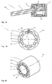
- magnetorheological transmission device with one or more poles and one or more elevations.
- elevations or the like are provided between the two components of the magnetorheological transmission device, which protrude, for example, from one component in the direction of the other component.
- Only one survey can be provided or several can be provided. It is possible that at least one survey a ball or a roller or other rotary body is arranged, which is at least partially received by the survey.
- elevations are provided on one component, it is preferably that at least one pole or at least one magnetization unit or at least one magnet or a coil is provided on the other component.
- the number of magnetization units or poles can be 1 or even greater.
- the shape of the surveys can basically be arbitrary and e.g. be half round, pointed or blunt.
- the receiving area of rotating bodies is preferably designed correspondingly rounded.
- One or more magnetization units or poles can be designed as an electric coil plus core, or as a permanent magnet, or consist of remanence material or a combination of these.
- the distances between individual elevations and / or magnetization units are preferably approximately constant, but may also be arbitrary.
- the depth, i. the radial extent or the axial extent of individual elevations or magnetization units to others may be different.
- the field strength applied or acting on the individual magnetization units can also vary in particular at the same time.
- the speed of rotation of the rotary body need not be equal to the rolling speed, it may also differ, e.g. through sub-translations or translations.
- the inner part, which by the surveys z. B. is formed star-shaped, may be stored eccentrically to the outer part.
- An application of such a magnetorheological transfer device may be e.g. as a haptic button with grid or in furniture and drawer slides done with positions.
- the magnet or each magnetization unit or the inner part and / or the outer part may also consist of remanent material.
- the device When used on a steering column, the device may serve to brake the steering around the central position, e.g. in a home-made smooth-running power steering, the steering becomes heavier, resulting in e.g. when driving straight on a highway is advantageous.
- a magnetorheological transmission device can brake such smooth-running steering systems and increase driving comfort through a torque adapted to the respective situation or the user.
- End stops can be realized with a magnetorheological transmission device. This allows functions for hydraulic steering systems, which previously could only be realized via electronic steering systems.
- magnetorheological fluids concatenate very quickly upon application of a magnetic field, in the normal state, e.g. when driving a car, when the magnetic field is switched off. As a rule, it is completely sufficient to switch on only when a first rotation angle change is initiated. This can save a lot of energy.
- a basic moment can be realized with remanence.
- a dynamic magnetic field can be built up which can also pulse to create a virtual grid.
- the senor or the sensors can be used to measure the distance of the vehicle when parking, so that separate sensors are not needed. It is also possible to make the control so that the door first opens slightly and then a grid comes, which is getting finer. This would be practically a haptic display for door openers realized that indicates when you come near the stop.
- the magnetic field for remagnetization can be impressed from the outside.
- a corresponding coil can be used, which is replaced by e.g. a cylinder acts.
- the coupling intensity of at least two couplable components is influenced by a magnetorheological transmission device, the coupling intensity being influenced in at least one channel which contains a magnetorheological medium with magnetically polarisable particles that can be influenced by a magnetic field, and at least one magnetic field generating device with at least one magnetic field generation device is generated in the channel to influence the magnetorheological medium in the channel with the magnetic field.
- at least one rotary body is provided in the channel and a free distance between the rotary body and the component is greater than ten times the diameter of the typical mean magnetically polarizable particle.
- the channel is at least temporarily and at least partially acted upon by the magnetic field of the magnetic field generating device to selectively chain the particles and / or to wedge or release with the rotary body.
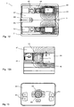
- FIG. 1 shows a highly schematic cross-sectional view of a magnetorheological transmission device 1 according to the invention for influencing the power transmission between two components 2 and 3. It is between the two components 2 and 3 in Fig. 1 a rotary body 11 is provided as a separate part 4.
- the rotary body 11 is formed here as a ball 14. But it is also possible to form rotary body 11 as a cylinder or ellipsoids, rollers or other rotatable rotary body. Also in the actual sense not rotationally symmetric rotary body such as a gear 34 or rotating body 11 with a specific surface structure can be used as a rotating body.
- the rotary body 11 are not used for storage relative to each other, but for the transmission of torque.
- a channel 5 is provided, which is filled here with a medium 6.
- the medium here is a magnetorheological fluid 20, which comprises, for example, as a carrier fluid an oil in which ferromagnetic particles 19 are present. Glycol, fat, viscous substances can also be used as a carrier medium, without being limited thereto.
- the carrier medium can also be gaseous or it can be dispensed with the carrier medium (vacuum). In this case, only particles which can be influenced by the magnetic field are filled into the channel.
- the ferromagnetic particles 19 are preferably carbonyl iron powder, wherein the size distribution of the particles depends on the specific application. Concretely preferred is a distribution particle size between one and ten micrometers, but also larger particles of twenty, thirty, forty and fifty microns are possible. Depending on the application, the particle size can become significantly larger and even penetrate into the millimeter range (particle balls).
- the particles may also have a special coating / coating (titanium coating, ceramic, carbon mantle, etc.), so that they better withstand the high pressure loads occurring depending on the application.
- the MR particles can not only be made of carbonyl iron powder (pure iron) but, for example, also made of special iron (harder steel).
- the rotary body 11 is offset by the relative movement 17 of the two components 2 and 3 in rotation about its axis of rotation 12 and runs virtually on the surface of the component 3 from. At the same time, the rotary body 11 runs on the surface of the other component 2, so that there is a relative speed 18.
- the rotary body 11 has no direct contact with the surface of the component 2 and / or 3 and therefore does not roll directly therefrom.
- the free distance 9 from the rotary body 11 to one of the surfaces of component 2 or 3 is e.g. 140 ⁇ m.
- the free distance is in particular between 75 .mu.m and 300 .mu.m, and particularly preferably between 100 .mu.m and 200 .mu.m.
- the free distance is in particular at least ten times the diameter of a typical mean particle diameter. Preferably, the free distance is at least ten times the largest typical particle. Due to the lack of direct contact results in a very low (s) basic friction / force / moment in the relative movement of the components 2 and 3 to each other.
- the field lines are formed depending on the distance between the rotating bodies 11 and the components 2, 3.
- the rotating body is made of a ferromagnetic material and, for example, here from ST 37.
- the steel type ST 37 has a magnetic permeability ⁇ r of about 2000.
- the field lines pass through the rotating body and concentrate in the rotating body. At the here radial inlet and outlet surface of the field lines on the rotary body there is a high flux density in the channel 5.
- the inhomogeneous and strong field leads to a local and strong networking of the magnetically polarizable particles 19.
- the rotary body 11 and component 2, 3 at least partially made of ferromagnetic material, which is why the magnetic flux density is higher, the smaller the distance between the rotary body 11 and component 2, 3.
- a substantially wedge-shaped region 16 forms in the medium, in which the gradient of the magnetic field strongly increases at the acute angle at the contact point / the region of the smallest distance.
- FIG. 1 Magnetic field generating device 7 is not shown, the individual particles 19 of the magnetorheological fluid 20 chain along the field lines of the magnetic field 8.
- FIG. 1 drawn vectors represent the relevant for influencing the MRF 20 area of the field lines only roughly schematically.
- the field lines enter the channel 5 substantially normal to the surfaces of the ferromagnetic components and, especially in the acute-angled region 10, do not have to be rectilinear.
- the acute-angled regions 10 may have a wedge shape 16, for example, in the case of cylindrical bodies 11. Due to the wedge shape 16, the further rotation of the rotating body 11 is hindered, so that the effect of the magnetic field on the magnetorheological fluid is enhanced, since a stronger cohesion of the local medium 6 results from the acting magnetic field within the acute-angled area 10. As a result, the effect of the magnetorheological fluid in the accumulated heap is increased (the chain formation in the fluid and thus the cohesion or the viscosity), which makes the further rotation or movement of the rotating body 11 more difficult.
- the forces which can be transmitted directly through the applied magnetic field represent only a small part of the forces which can be transmitted by the device.
- the wedge formation and thus the mechanical force amplification can be controlled by the magnetic field.
- the mechanical reinforcement of the magnetorheological effect can go so far that a force transmission is possible even after switching off an applied magnetic field, when the particles were wedged.
- the wedge effect of the acute-angled regions 10 results in a considerably greater effect of a magnetic field 8 of a specific thickness.
- the effect can be increased many times over.
- an approximately ten times greater influence on the relative speed of two components 2 and 3 was observed with each other as in the prior art MRF couplings.
- the possible gain depends on different factors. If necessary, she can be reinforced by a larger surface roughness of the rotary body 11. It is also possible that on the outer surface of the rotary body 11 outwardly projecting projections are provided, which can lead to an even stronger wedge formation.
- the wedge effect or the wedge effect is distributed over the surface of the rotary body 11 and the components 2 or 3.
- FIG. 2 shows a coupling 50 with a magnetorheological transmission device 1 according to the invention, wherein the components 2 and 3 are designed here as rotating parts.
- the magnetic field generating device 7 is provided, which here comprises a coil 26 and a permanent magnet 25.
- the coil 26 is connected to a control or regulating device 27.
- a permanent magnetic field 8 can be applied, wherein the magnetic field acting in the channel can be modulated by activation of the electric coil 26. So the acting magnetic field can be lowered or strengthened.
- the coil 26 is designed to deliver strong magnetic pulses, with which the permanent magnet 25 is permanently changed.
- the magnetization of the permanent magnet 25 can be selectively changed between zero and its remanence.
- the magnetic field strength of the permanent magnet 25 remains virtually unchanged for any length.
- the effective field strength of the permanent magnet 25 can be adjusted as often as required, so that a specific field strength can be generated even without a permanent power supply.
- an energy store 28 can be provided, which is designed, for example, as a capacitor and keeps the energy ready for at least one pulse.
- at least one sensor 29 may be provided, for example, the measures acting magnetic field strength. It is also possible for the sensor to detect further data, such as the torque, the rotational speed, the relative speed, the angle of rotation of the two components 2 and 3 relative to one another or the prevailing temperature or the like. If necessary, corresponding steps can be initiated if, for example, the permissible temperature of the magnetorheological transmission device 1 is exceeded.
- a mechanical adjustment device in which the field strength in the channel can be changed, for example, by moving the magnet, pole shoes or shielding plates.
- This mechanical adjustment can also be used in combination with a Bowden cable and / or an electrical adjustment, for example when the permanent magnet sets a basic force as the operating point and a coil control can change the force around this operating point.
- FIG. 3 shows a magnetorheological transmission device 1 according to the invention, which is designed as a brake 40.
- the magnetorheological transmission device 1 has a formed as a shaft component 2, the rotational movement relative to the fixed component 3 can be influenced.
- bearings 42 are provided for rotatably supporting the components 2, 3rd.
- the rotary bodies 11 between the components 2 and 3 are designed here as balls 14 and are surrounded by the medium 6 and the magnetorheological fluid 20.
- seals 91 are provided between the rotating bodies 11 and the bearings 42.
- a magnetic field generating device 7 embodied, for example, as a coil serves for purposeful control of a magnetic field 8, which also extends through the rotary bodies 11 and is aligned there substantially transversely and in this case even perpendicular to the relative movement of the two components 2 and 3. Due to the rotational movement of the rotary body 11, when the magnetic field 8 is switched on, a concatenation of the particles 19 in the magnetorheological Fluid 20 causes, which arise at each individual rotary body 11 of the acute-angled regions 10, which significantly hinder further rotation of the component 2 relative to the component 3. The effect of the magnetorheological fluid is significantly enhanced.
- the MRF wedge housing can be pushed over an (existing) drive shaft, this is then braked depending on the acting magnetic field 8, wherein the MRF wedge between the shaft surface and the rotating bodies 11 sets.
- Normal brakes or clutches regularly require a washer or other flange parts and have a fixed shaft position when viewed axially.
- the shaft can be displaced axially, without this having an effect on the wedge effect.
- a separate race need not be applied to the shaft 2 component.
- FIG. 4 shows a magnetorheological transmission device 1 for influencing the linear movements of two components 2 and 3 relative to each other.
- the magnetorheological transmission device 1 comprises a rod 32 which dips into the component 3 and is provided there relative to the component 3 displaceable.
- the magnetorheological transmission device 1 according to FIG. 4 can be designed so that in addition to a longitudinal movement and a rotational movement of the two components 2 and 3 to each other and can be influenced by a magnetic field.
- FIG. 5 shows an enlarged cross section of the central portion of the magnetorheological transfer device 1 according to FIG. 4 .
- the electric coil 26 is the electric coil 26 as magnetic field generating device 7 in order to generate a targeted magnetic field 8.
- a rotary body 11 Radially between the rod 32 and the component 3 balls are arranged as a rotary body 11, which are provided in the axial direction relative to the rod 32 and the component 3 movable and move relative to each other during a relative movement of the component 2 and 3 and in particular are set in rotational motion can. at Such a rotational movement results in the acute-angled regions 10 which, upon activation of the magnetic field 8, lead to a concatenation of the particles 19 of the magnetorheological fluid 20 as a medium 6 and thus delay or aggravate or even block the relative movement of the rod 32 to the component 3.
- Such a magnetorheological transmission device 1 can also be used as a vibration or shock absorber or the like.
- FIG. 6 shows a magnetorheological transmission device 1 with a standing component 2 and designed as a shaft rotatable component 3, are arranged in the cylindrical rotating body as a rotating body 11 between the component 2 and the component 3 and surrounded by a medium 6, which on a magnetic field 8 a Magnetic field generating device 7 reacts.
- the magnetorheological transmission device 1 in FIG. 6 For example, used as a brake, the braking energy is dissipated in the medium 6. Frequent and / or strong braking can supply a lot of energy to the medium, which can lead to considerable heating of the medium or fluid 6 and the rotary body 11.
- a cooling device 41 may be provided, which can be forcibly activated, for example via a pump 39.
- the pump 39 can also be integrated into the bearing as a separate component which utilizes the relative movement.
- at least a part of the rotary body and / or the components is designed such that a relative movement moves at least part of the medium in the cooling circuit.
- Another advantageous effect of a force-activated cooling device can be a continuous mixing of the liquid and the provision of sufficient MRF, wherein the cooling device can serve as a reservoir for the MRF liquid.
- FIG. 8 shows a cross section of the magnetorheological transmission device 1 from FIG. 7 ,
- the component 2 has a rotatably received rotary body 11 which is provided with a gear 34.
- the gear 34 meshes with a rack 35 of the Component 3. If the component 2 is moved relative to the component 3, this leads to a rotational movement of the rotary body 11, since the gear 34 of the rotary body 11 meshes with the rack 34 of the component 3.
- a magnetorheological fluid 20 can react to the magnetic field by applying, for example, an external magnetic field.
- an acute-angled region 10 with a wedge shape 16 forms between the plates of the component 3 and the rotary body 11, which makes a further relative movement of the components 2 and 3 to each other more difficult.
- the gear 34 and the rack 35 can be dimensioned depending on the application so that the rotational speed of the relative speed of the components 2 and 3 corresponds to each other or is increased or decreased or greatly increased or greatly reduced.
- the component 3 can also consist of only one plate, then only an acute-angled region 10 with a wedge shape 16 results.
- FIG. 9 shows a prosthesis 60, in which in the knee and ankle magnetorheological transmission devices 1 are used. By activating the corresponding magnetic fields 8, a rotational movement can be damped or blocked, which facilitates staying in one position and allows a more natural movement.
- FIG. 10 shows a highly schematic representation of a cross section through a coupling 50.
- two clutch plates 21 are provided, which are arranged at a small distance from each other.
- a medium 6 is provided, which is designed for example as a magnetorheological fluid 20.
- 21 rotary body 11 are provided between the clutch plates, which are formed here as a rotary body 11 in the form of balls 14. In a relative movement of the clutch plates 21 to each other, the rotary body 11 are set in rotary motion.
- a magnetic field 8 by a magnetic field generating device 7, this leads to the formation active acute-angled regions 10, which significantly inhibit a further relative movement of the clutch plates 21 to each other.
- FIG. 11 shows a further embodiment of a magnetorheological transmission device 1 according to the invention, which is designed here as a shoe 70 and is shown only schematically.
- the shoe 70 has an upper part 36 and a sole 37, which are connected to each other via a hinge with a magnetorheological transmission device 1.
- a spring means or foam 38 is provided which pre-loads the shoe 70 to its home position.
- a shoe 70 can be used to continuously compensate for misalignments of the human foot.
- a tilting of the running shoe sole may result in greater support for the inner foot area, which is advantageous, for example, in the event of overpronation.
- the footwell shape adapts to the new conditions, so that the runner with a shoe 70 according to the invention occupies a good position in the running shoe. It is also conceivable that for larger required adjustment of the adjustment process is divided into several steps.
- a damping material can be integrated into the shoe.
- Sensors can detect the actual state and make adjustments by means of a control and / or regulating electronics. It is also possible to place an actuator at the end of the running shoe and not just under the running shoe or under the heel. In practice, then a knob or knob can be arranged at the end of the running shoe.
- Fig. 12 shows a control knob or knob 80 with a magnetorheological transmission device 1 according to the invention in a schematic cross section.
- the housing 45 as a component 2 may for example be fixedly mounted on a device.
- the shaft 47 as a component 3 is connected to the rotary member 85. Both components 2 and 3 are rotatably supported by bearings 42 against each other.
- a thin gap as a free space 9 is located between the rotary body 11 and the housing 45 and also between the rotary body 11 and the shaft 47.
- the space surrounding the rotary bodies 11 and possibly almost the entire interior can be filled with a magnetorheological fluid as the medium 6 ,
- a sealing ring 46 acts as a seal against the bearing 42, which is thus protected from the particles in the magnetorheological fluid.
- a magnetic field 8 is generated which, as the field lines shown by way of example show, passes through the rotary bodies 11 and extends essentially otherwise within the housing 45 and the shaft 47.
- a corresponding resistance is generated in the medium 6 or the MR fluid, so that upon rotation of the rotary part 85 a corresponding resistance can be felt.
- temporally pulsed or pulsating operation through which a pulsating resistance and thus a rasterization becomes noticeable when turning.
- the respective current angular position can be detected via a rotary encoder 52.
- a rotary encoder 52 can also be supplemented by a torque sensor.
- Fig. 12b shows a schematic enlarged section Fig. 12 in which a rotary body 11 is completely and a behind it arranged rotary body 11 is only partially visible, since it is partially covered by the front rotary body 11 and a little by the shaft 47.
- the gap 9 or free distance above and below the rotary body 11 is clearly visible.
- the free distances may be the same radially inward and radially outward, but it must Not.
- the free distance 9 corresponds to the bearing play in the bearing terminology.
- the double running clearance corresponds to the bearing clearance of a bearing.
- Fig. 13 shows a knob 80 which is disposed on a display 81 on a display.
- the display 81 can also be made touch-sensitive as a touch screen and can display buttons or buttons 83, for example. It is possible, for example, that the keys 83 are displayed or activated depending on the program and / or selection in order to facilitate the individual operation of the user.
- Two-dimensional haptic buttons or knobs 80 can also be made with an additional MRF shear mode.
- An MRF haptic button can be made very compact for adjusting devices in SLR cameras and other cameras, as well as game consoles and other hand-held computers.
- Such small footprint MRF couplers are well suited for cameras and other outdoor applications because of the small footprint and low power consumption in the milliwatt or lower range.
- the grid is adjustable depending on the situation.
- Three-dimensional motion elements with variable feel and robust and precise storage are basically difficult to manufacture and therefore not inexpensive.
- the combination e.g. a pendulous arrangement of the rotating body with a magnetorheological fluid, however, is very inexpensive to produce.
- a four - dimensional rotary knob which can be moved in three directions and additionally rotated, for example Will be provided.
- buttons are also possible on touch-sensitive displays such as touch displays in mobile phones, PDAs, smartphones, portable and stationary computers and monitors, game consoles, tablet PCs, laptops, etc.
- touch-sensitive displays such as touch displays in mobile phones, PDAs, smartphones, portable and stationary computers and monitors, game consoles, tablet PCs, laptops, etc.
- Such a haptic element 1 can also be designed to be foldable / pivotable and, e.g. be moved from a rest position on the edge to a position above the display. Once the haptic element is over the display, the display may change in the display, i. a menu appears below or around the button.
- an elastic / deformable element which is e.g. as a flexible and semi-rigid arm made of coiled metal tubing in the form of a gooseneck can exist.
- One advantage is that the user does not always have to reach the screen, which reduces pollution.
- the user can also press on a separate control bar with one finger to select the type of desired operation. He then performs the desired action with the rotary control.
- the grid of the rotary knob then adapts automatically, eg "On” - “Off” or a volume control with a grid, possibly with a dynamic stop. If the screen during the operation (Such as mobile phones or hand-held computers - 90 ° from portrait to long format), then the grid adapts automatically, ie it rotates. For example, if the adjustment range is from 6:00 to 12:00 when tilting up, then this would be clockwise without adjustment when turning 90 ° from 12:00 to 6:00. This also applies if the display is installed in the button itself.
- Such a haptic element can be tactile in all or a few directions (just turn, turn and press, joystick, etc.). Depending on the chosen action, the haptic is adjusted.
- An advantage may also be found in selecting e.g. list such as a phonebook list, since such large finger entries are often too small to "target".
- the haptic knob provides feedback and the user knows what he is doing when, e.g. just dark.
- Fig. 14 shows such a 3D button as a joystick 90 which is pivotally provided in different directions.
- a haptic grid can be realized.
- magnetic field lines 8 are shown. In this case, very low forces occur, whereby the MRF particles are not damaged by high surface pressures.
- Fig. 15 is a schematic view of a knob 80 is shown as a magnetorheological transfer device 1, which has an outer component 2 and an inner component 3.
- a gap 86 between the two components 2 and 3 is an MRF.
- projections 49 which act as radial projections.
- permanent magnets 25 are provided at predetermined angular intervals as magnetic field generating means or magnet units or protrusions on the component 2. The magnetic fields of the permanent magnets 25 lead to a local clustering in the medium 6. This is the effect is even stronger, so that significant torque can be absorbed.
- the arrangement of the magnet units 87 results in a tactile detent when rotating the knob 80.
- the elevations are partially formed by separate rotary body 11, which are arranged in corresponding recesses 88 of the projections 49, and preferably can rotate therein.
- Fig. 16 shows a knob 80, in which between the inner component 3 and the outer component 2 rotary body 11 and rolling body 51 are provided.
- the magnetic field passes radially through the gap and / or the rotary body 51. It is also possible for the magnetic field to pass axially through the gap and / or the rotary bodies 51, e.g. axially on one side and out on the other side. Furthermore, a combination of the aforementioned alternatives is possible.
- the cage may also be provided with a friction-enhancing layer or be made of a special material, whereby the torque difference between "turned on” and “off” increases.
- a linear mode of operation may also be possible. It can also be used ball bearings or linear bearings with cage or linear ball bearings to achieve a strong support.
- the entire structure is very simple and inexpensive to produce, since such rotary bodies are mass-produced.
- plastic bound MRF such as foam or a sponge.
- a solid lubricant e.g. Lithium, graphite or MoS2 or the like may be mixed with carbonyl iron powder.
- Fig. 17 shows an embodiment of a magnetorheological transmission device 1, in which a linear movement such as a stroke or the like via a spindle such as a ball screw or a simple spindle is converted into a rotational movement.
- the one component 2 is designed as a threaded spindle 93 and is moved linearly. On it sits a spindle nut 98. A linear movement is converted into a rotary motion. It can be provided for storage bearings 42, which are then sealed by a seal 91.
- the rotary bodies 11 are arranged in a gap 5, which is filled with MRF.
- the gap can be exposed to a magnetic field of the magnetic field generating device 7, whereby the relative movement of the components 2 and 3 is attenuated and in turn the stroke movement is influenced. It is possible to use it in different applications, for example in sports equipment or washing machines as dampers.
- the magnetorheological transmission device 1 can be extended as an MRF brake by a rotary encoder 29.
- the detection of a rotational movement is cheaper and easier to implement as the detection of a longitudinal movement. This also applies to the sealing.
- a torque sensor can also be used.
- one or at least one permanent magnet may be provided, which is adjustable by motor or by hand. It is also possible to use a sliding shield. In all cases, a mechanical adjustment of the braking effect and thus the wedge effect is possible. This can for example be used to compensate for physical variables such as temperature, pressure, speed or the like. The operation can be done directly or via eg a Bowden cable. The adjustment can be stepless.
- FIGS. 18 and 19 show an MRF transmission device 1 in a toggle lever in two different views.
- the toggle lever has two arms, which form the rotatable components 2 and 3 here.
- Bearings 42 may be provided for supportive support.
- a magnetic field generating device 7 serves to generate a magnetic field in the gap in which an MRF and rotary body 11 are present. Due to the sufficiently large but not too large free space 9 can optionally be built up a very high braking or clutch torque.
- a seal 91 seals to the outside.
- the MRF transmission device 1 can also be supplemented by a rotary encoder and / or a torque sensor and / or other sensors.
- Such magnetorheological transmission devices can be used for fittings in furniture. For example, as a linear unit for drawer guides, etc. By the rotary body is doing a sufficient guide, while at the same time the pull-out force is variable.
- wedge effect magnetorheological transfer devices 1 can be used as a variable and adjustable brake on kitchens and other furniture. Panning, such as The opening of doors or flaps on furniture can be restricted to certain areas while allowing quick opening.
- the setting may e.g. via rotatable permanent magnets or electrically or via a lever or rotary lever.
- Fig. 20 shows an MRF transmission device 1 in a highly schematic front view and Fig. 21 shows the transmission device 1 from Fig. 20 in a highly schematic Partial cross-section.
- An inner shaft 3 is arranged rotatably in an outer hollow shaft as component 2.
- the outer hollow shaft 2 may be fixed.
- two electromagnets, each with a laminated core 97, are arranged here as magnetic field generating devices 7. It can also be provided three or more electromagnets. It is also possible that only one magnet is provided. Instead of electromagnets at least partially permanent magnets can be used.
- a gap 5 is provided, which is filled with an MRF.
- two rotary bodies 11 are arranged, which are designed here as a substantially cylindrical rotary body.
- the cylindrical rotating bodies 11 may be provided with pinions 95, which are forcibly guided in a toothing 96, so that the rotary body 11 is provided for a continuous rotational movement.
- the region of the toothing 96 can be substantially field and MRF-free.
- the coupling takes place here predominantly via the wedge forming in the gap 5.
- the transmission device can be executed with different gears or translations, but also without, for the forced rotation of the rotary body 11.
- Imaged magnetic field generating device 7 each have a north pole 94a and a south pole 94b, which adjoin each other at a small distance to the channel 5 with the MRF therein.
- the magnetic field lines pass through the two poles 94a and 94b in the annular gap as a channel 5 and form there heap of solidifying MRF when the field is applied.
- the cylindrically formed in the region of the annular gap rotating body run in the forced rotational movement on the MRF structures. The resulting wedge effect and the acute-angled area on the rotating bodies leads to a very strong braking torque.
- Such a magnetorheological transmission device 1 as a wedge coupling after Fig. 20 can in a modification after Fig. 22 also having a coil mounted in a non-rotating housing which selectively generates a magnetic field.
- the magnetic field is conducted via pole disks 99 and 99a and closes via fingers 100 and 100a, which are fixed axially to the pole disks 99 and 99a.
- the MRF is solidified into cluster 103 in the MRF channel 5 or gap.
- the pole disks 99 and 99a rotate with the drive shaft 2. If the solidified MRF regions 103 meet the rotary bodies 11 arranged in the crescent-shaped recesses 104, which are fastened to the output shaft 3, they are briefly entrained as a function of the magnetic field.
- the coils may be provided fixed. Transmission of the power supply via slip rings is not necessary.
- the magnetic flux is introduced via the pole disks 99 and 99a and their pole fingers 100 and 100a in the channel 5, where the field lines close and lead to the formation of the heaps 103, which cooperate wedge-shaped with the rotating bodies 11.
- pole disks 99 and 99a are held in a ring made of plastic here, which is separated via an air gap 101 from the externally rotating component 2 or shaft.
- all components are ferromagnetic, except the part designed in particular as a plastic part between the pole disks 99 and 99a and the input and output shafts 2 and 3.
- MRF heaps can be controlled individually and independently of each other.
- magnetorheological transmission devices 1 with wedge effect into a wheel hub of a vehicle and, for example, a bicycle in order, for example, to brake.
- the required electrical energy can draw power directly from the built-in dynamo, which is in particular connected in parallel.
- the Dynamo can be an energy recovery.
- the magnetorheological transmission device 1 can serve as MRF brake.
- MRF brake works purely electrically and reacts quickly, the use is well possible.
- Corresponding treads for the rotary body are available. A large part could be braked so over a Radnabendynamo. For operation on the handlebar only a power cable in connection with eg a potentiometer is needed or the transmission is wireless.
- the use is also possible as a brake in fitness equipment or as a clutch or brake on rowing machines.
- the principle can also be taken as a wedge coupling for coupling of units and in particular ancillary components in motor vehicles. Possibly. two MRF heaps can be provided relatively close together, so that the system does not open the same at a change of direction.
- the wedge and / or the magnetic field can also be generated on the inner ring and not only on Outer ring.
- the rotating body 11 and cages may be wholly or partially ferromagnetic and paramagnetic or diamagnetic. Also possible is a full-spherical design and a design in which all parts are made of the same material. It is also possible that some rotating bodies are ferromagnetic and e.g. made of steel while others are made of plastic. It is also possible to use rotary bodies and balls with different diameters.
- the magnetorheological transmission device 1 according to the invention can also be used for speed detection and in particular speed control.
- the torque can be set as a function of the speed.
- Large axial and radial forces can be generated via an oblique expanding mandrel.
- the particles may have a round, rod-shaped or any other shape.
- magnetorheological elastomers For example, at least one surface may also be a magnetorheological elastomer. In principle, a component may be provided with a magnetorheological elastomer. It is also possible to coat at least one rotating body 11 and / or at least one of the components 2, 3 with a magnetorheological elastomer.
- the magnetorheological transmission device 1 can also be designed as a valve, wherein a rotary body 11 or a plurality of rotary bodies 11 obstruct the channel.
- a magnetorheological transmission device can also be provided for the use of a magnetorheological fluid which is a product of BASF, in particular the product "Basonetic".
- the rheological fluid may consist of a variety of constituents, which may be alone or in combination: Fe, Carbon steel, NdFeB (neodymium), alnico, samarium, cobalt, silicon, carbon fiber, stainless steel, polymers, soda-lime glass, soda-lime glass, ceramic and non-magnetic metals, and the like. Dimorphic magnetorheological fluids with nanotubes and / or nanowires are also possible.
- the carrier liquid may in particular consist of the following components or a combination thereof: oils and preferably synthetic or non-synthetic oils, hydraulic oil, glycol, water, fats and the like.
Landscapes
- Engineering & Computer Science (AREA)
- General Engineering & Computer Science (AREA)
- Mechanical Engineering (AREA)
- Physics & Mathematics (AREA)
- Electromagnetism (AREA)
- Braking Arrangements (AREA)
- Lubricants (AREA)
Applications Claiming Priority (3)
| Application Number | Priority Date | Filing Date | Title |
|---|---|---|---|
| DE102010045436 | 2010-09-15 | ||
| DE102010055833A DE102010055833A1 (de) | 2010-09-15 | 2010-12-23 | Rheologische Übertragungsvorrichtung |
| PCT/EP2011/004623 WO2012034697A1 (de) | 2010-09-15 | 2011-09-15 | Magnetorheologische übertragungsvorrichtung |
Publications (2)
| Publication Number | Publication Date |
|---|---|
| EP2616704A1 EP2616704A1 (de) | 2013-07-24 |
| EP2616704B1 true EP2616704B1 (de) | 2014-11-12 |
Family
ID=45756180
Family Applications (1)
| Application Number | Title | Priority Date | Filing Date |
|---|---|---|---|
| EP11770690.3A Active EP2616704B1 (de) | 2010-09-15 | 2011-09-15 | Magnetorheologische übertragungsvorrichtung |
Country Status (5)
| Country | Link |
|---|---|
| US (1) | US9091309B2 (zh) |
| EP (1) | EP2616704B1 (zh) |
| CN (3) | CN105179516B (zh) |
| DE (1) | DE102010055833A1 (zh) |
| WO (1) | WO2012034697A1 (zh) |
Cited By (2)
| Publication number | Priority date | Publication date | Assignee | Title |
|---|---|---|---|---|
| DE202022105705U1 (de) | 2022-10-10 | 2022-10-27 | Genima Innovations Marketing Gmbh | Hochdruckpumpe |
| DE102021118281A1 (de) | 2021-07-06 | 2023-01-12 | Inventus Engineering Gmbh | Vorrichtung mit einer magnetorheologischen Bremsvorrichtung und Verfahren |
Families Citing this family (119)
| Publication number | Priority date | Publication date | Assignee | Title |
|---|---|---|---|---|
| US10318002B2 (en) * | 2010-09-15 | 2019-06-11 | Inventus Engineering Gmbh | Magnetorheological transmission device |
| DE102015110634A1 (de) * | 2015-07-01 | 2017-01-05 | Inventus Engineering Gmbh | Minicomputer und Verfahren |
| DE102015110633A1 (de) | 2015-07-01 | 2017-01-05 | Inventus Engineering Gmbh | Haptische Bedieneinrichtung und Verfahren |
| US10429959B2 (en) | 2010-09-15 | 2019-10-01 | Inventus Engineering Gmbh | Minicomputer with a rotating unit and method of operating the minicomputer |
| US10502271B2 (en) | 2010-09-15 | 2019-12-10 | Inventus Engineering Gmbh | Haptic operating device with a rotating element and method for operating electronic equipment with the haptic operating device |
| US10007290B2 (en) | 2010-09-15 | 2018-06-26 | Inventus Engineering Gmbh | Haptic operating device with a rotating element and method |
| US10976827B2 (en) * | 2010-09-15 | 2021-04-13 | Inventus Engineering Gmbh | Input device and method of operating an input device |
| US9305120B2 (en) | 2011-04-29 | 2016-04-05 | Bryan Marc Failing | Sports board configuration |
| US10189534B2 (en) * | 2012-06-26 | 2019-01-29 | Dt Swiss Inc. | Suspension control for a human-powered two-wheeled vehicle and method |
| DE102012017423B4 (de) | 2012-09-04 | 2015-07-09 | Inventus Engineering Gmbh | Magnetorheologische Übertragungseinrichtung |
| DE102013005442B3 (de) * | 2013-03-31 | 2014-08-21 | Inventus Engineering Gmbh | Ventileinrichtung und Verfahren |
| US9753436B2 (en) * | 2013-06-11 | 2017-09-05 | Apple Inc. | Rotary input mechanism for an electronic device |
| KR101341089B1 (ko) * | 2013-07-04 | 2013-12-19 | 연합정밀주식회사 | 자기유변유체를 이용한 회전식 액추에이터 및 역감 제공 방법 |
| US20150022340A1 (en) | 2013-07-16 | 2015-01-22 | Leeo, Inc. | Electronic device with environmental monitoring |
| US9116137B1 (en) | 2014-07-15 | 2015-08-25 | Leeo, Inc. | Selective electrical coupling based on environmental conditions |
| KR102430508B1 (ko) | 2013-08-09 | 2022-08-09 | 애플 인크. | 전자 디바이스용 촉각 스위치 |
| FR3010546B1 (fr) * | 2013-09-09 | 2016-12-23 | Dav | Interface de commande a retour haptique |
| JP5694481B1 (ja) * | 2013-10-30 | 2015-04-01 | ファナック株式会社 | 主軸とモータとの間の動力伝達部の異常を検出するモータ制御装置 |
| KR20160088335A (ko) * | 2013-11-22 | 2016-07-25 | 프레셔라이트(피티와이) 리미티드 | 차량 타이어의 압력 제어 장치 |
| US9541142B2 (en) * | 2014-01-31 | 2017-01-10 | Bell Helicopter Textron Inc. | Magnetorheological flight control clutch system |
| US10048802B2 (en) | 2014-02-12 | 2018-08-14 | Apple Inc. | Rejection of false turns of rotary inputs for electronic devices |
| WO2015124434A1 (de) * | 2014-02-24 | 2015-08-27 | BSH Hausgeräte GmbH | Haushaltsgerät mit stelleinrichtung |
| CN106574699B (zh) * | 2014-05-16 | 2019-12-03 | 庞巴迪公司 | 用于飞行器飞行控制表面的致动器和方法 |
| CN103982624B (zh) * | 2014-05-28 | 2016-08-24 | 沈阳化工大学 | 一种可调刚度和阻尼的齿轮 |
| US9372477B2 (en) | 2014-07-15 | 2016-06-21 | Leeo, Inc. | Selective electrical coupling based on environmental conditions |
| US9393901B2 (en) * | 2014-07-21 | 2016-07-19 | Kostal Of America | Turn signal systems and methods |
| JP6550219B2 (ja) * | 2014-08-06 | 2019-07-24 | Ntn株式会社 | 車輪用軸受装置 |
| US9092060B1 (en) * | 2014-08-27 | 2015-07-28 | Leeo, Inc. | Intuitive thermal user interface |
| WO2016036747A1 (en) | 2014-09-02 | 2016-03-10 | Apple Inc. | Wearable electronic device |
| US10102566B2 (en) | 2014-09-08 | 2018-10-16 | Leeo, Icnc. | Alert-driven dynamic sensor-data sub-contracting |
| US9445451B2 (en) | 2014-10-20 | 2016-09-13 | Leeo, Inc. | Communicating arbitrary attributes using a predefined characteristic |
| US10026304B2 (en) | 2014-10-20 | 2018-07-17 | Leeo, Inc. | Calibrating an environmental monitoring device |
| EP3251139B1 (en) | 2015-03-08 | 2021-04-28 | Apple Inc. | Compressible seal for rotatable and translatable input mechanisms |
| US10099776B2 (en) * | 2015-03-27 | 2018-10-16 | Hamilton Sundstrand Corporation | Rheologic fluid coupler for redundant linear electromechanical actuators |
| EP3088263B1 (en) | 2015-04-28 | 2017-12-20 | Bitron S.p.A. | Pedal control device, particularly for a motor-vehicle |
| CN105179517B (zh) * | 2015-09-25 | 2018-02-09 | 江苏兰菱机电科技有限公司 | 磁粉加载器 |
| DE102015117594A1 (de) * | 2015-10-15 | 2017-04-20 | Inventus Engineering Gmbh | Drehdämpfer |
| DE102015118752B4 (de) * | 2015-11-02 | 2023-01-19 | Dr. Ing. H.C. F. Porsche Aktiengesellschaft | Rotationsbremsanordnung |
| US20180363769A1 (en) * | 2015-11-02 | 2018-12-20 | Kongsberg Automotive Ab | A Shift Actuator Assembly for a Vehicle Transmission |
| US10805775B2 (en) | 2015-11-06 | 2020-10-13 | Jon Castor | Electronic-device detection and activity association |
| US9801013B2 (en) | 2015-11-06 | 2017-10-24 | Leeo, Inc. | Electronic-device association based on location duration |
| WO2017083970A1 (en) | 2015-11-16 | 2017-05-26 | Exonetik Inc. | Human-hybrid powertrain for a vehicle or moving equipment using magnetorheological fluid clutch apparatus |
| US9505461B1 (en) | 2016-04-05 | 2016-11-29 | Rene M. Ortega | Bicycle with adjustable pedaling resistance using magnetorheological based fluid |
| EP3449146B1 (en) * | 2016-04-25 | 2021-02-24 | Exonetik Inc. | Multimode control system for magnetorheological fluid actuator unit |
| US10061399B2 (en) | 2016-07-15 | 2018-08-28 | Apple Inc. | Capacitive gap sensor ring for an input device |
| US10019097B2 (en) | 2016-07-25 | 2018-07-10 | Apple Inc. | Force-detecting input structure |
| DE112017003814T5 (de) * | 2016-07-29 | 2019-04-18 | Magna International Inc. | Automatisches fahrzeugverschlusssystem |
| US10918905B2 (en) * | 2016-10-12 | 2021-02-16 | Icon Health & Fitness, Inc. | Systems and methods for reducing runaway resistance on an exercise device |
| DE102016221206B4 (de) * | 2016-10-27 | 2018-05-09 | Schaeffler Technologies AG & Co. KG | Elektromechanischer Fahrwerksaktuator |
| DE102016121202A1 (de) | 2016-11-07 | 2018-05-09 | Otto Bock Healthcare Gmbh | Vorrichtung zum Unterstützen eines Armes |
| DE202016009088U1 (de) | 2016-11-07 | 2022-02-04 | Ottobock Se & Co. Kgaa | Vorrichtung zum Unterstützen eines Armes |
| US11002335B2 (en) | 2016-11-08 | 2021-05-11 | General Electric Company | Controllable magneto-rheological device for gas turbine engine |
| DE102017103809A1 (de) | 2017-02-24 | 2018-08-30 | Inventus Engineering Gmbh | Protheseneinrichtung mit einem Drehdämpfer |
| CA3062035A1 (en) * | 2017-05-12 | 2018-12-06 | Exonetik Inc. | Exoskeleton, orthosis, wearable device or mobile robots using magnetorheological fluid clutch apparatus |
| NL2018947B1 (en) * | 2017-05-19 | 2018-11-28 | Univ Delft Tech | Bearing device |
| DE102017111031A1 (de) | 2017-05-20 | 2018-11-22 | Inventus Engineering Gmbh | Haptische Bedieneinrichtung |
| DE102017114517A1 (de) * | 2017-06-29 | 2019-01-03 | Thyssenkrupp Ag | Verstellbare Lenksäule mit wenigstens einem MRF-Steller |
| EP3676156B1 (en) * | 2017-08-29 | 2021-06-09 | thyssenkrupp Presta AG | Steer-by-wire steering system of a motor vehicle with a feedback actuator having an integrated mrf bearing |
| DE102017218278A1 (de) * | 2017-10-12 | 2019-04-18 | Bayerische Motoren Werke Aktiengesellschaft | Verfahren zum Aktivieren eines sicherheitsrelevanten Bedienelements |
| US10598248B2 (en) | 2017-11-01 | 2020-03-24 | Simon Fraser University | Smart fluid damper |
| JP2021508368A (ja) * | 2017-12-06 | 2021-03-04 | ウエスチングハウス・エレクトリック・カンパニー・エルエルシー | 透過率と構造剛性率が可変のパネルアセンブリ |
| DE102018100390A1 (de) * | 2018-01-10 | 2019-07-11 | Inventus Engineering Gmbh | Magnetorheologische Bremseinrichtung |
| CN108105323B (zh) * | 2018-01-16 | 2024-03-15 | 宁波鑫邦粉末冶金有限公司 | 汽车减振器 |
| DE102018103112A1 (de) | 2018-02-13 | 2019-08-14 | Inventus Engineering Gmbh | Vorrichtung mit zueinander bewegbaren Komponenten |
| US10507111B2 (en) * | 2018-03-09 | 2019-12-17 | Stephen Bramblett Johnson | Magnetic prosthetic |
| US10677087B2 (en) | 2018-05-11 | 2020-06-09 | General Electric Company | Support structure for geared turbomachine |
| US10823003B2 (en) | 2018-05-25 | 2020-11-03 | General Electric Company | System and method for mitigating undesired vibrations at a turbo machine |
| US11360440B2 (en) | 2018-06-25 | 2022-06-14 | Apple Inc. | Crown for an electronic watch |
| US11561515B2 (en) | 2018-08-02 | 2023-01-24 | Apple Inc. | Crown for an electronic watch |
| CN211293787U (zh) | 2018-08-24 | 2020-08-18 | 苹果公司 | 电子表 |
| CN209625187U (zh) | 2018-08-30 | 2019-11-12 | 苹果公司 | 电子手表和电子设备 |
| EP3859180A1 (en) * | 2018-09-25 | 2021-08-04 | Alps Alpine Co., Ltd. | Torque generating device |
| US11493407B2 (en) | 2018-09-28 | 2022-11-08 | Ge Avio S.R.L. | Torque measurement system |
| DE102018124023A1 (de) * | 2018-09-28 | 2020-04-02 | Kiekert Aktiengesellschaft | Bewegungskopplungs-Einrichtung |
| DE102018222235A1 (de) * | 2018-12-19 | 2020-06-25 | Zf Friedrichshafen Ag | Drehsteuervorrichtung |
| US11815142B2 (en) | 2019-02-04 | 2023-11-14 | Vanderbilt University | Magnetorheological brake with high torque and fast response |
| DE102019121640A1 (de) * | 2019-02-11 | 2020-08-13 | Inventus Engineering Gmbh | Türkomponente und Verfahren |
| US11194299B1 (en) | 2019-02-12 | 2021-12-07 | Apple Inc. | Variable frictional feedback device for a digital crown of an electronic watch |
| CN109772731A (zh) * | 2019-03-12 | 2019-05-21 | 哈工大机器人(山东)智能装备研究院 | 18650型锂电池分选磁流变液机扫码装置及工作方法 |
| CN110016356B (zh) * | 2019-04-17 | 2023-10-20 | 青岛科技大学 | 一种5kg实验室用自动化裂解设备及裂解方法 |
| JP7271349B2 (ja) * | 2019-07-10 | 2023-05-11 | キヤノン株式会社 | 回転抵抗装置および電子装置 |
| DE102020104810A1 (de) | 2019-08-05 | 2021-02-11 | Inventus Engineering Gmbh | Eingabegerät und Eingabesystem sowie Verfahren zum Betreiben eines Eingabegeräts |
| DE102019213554A1 (de) * | 2019-09-06 | 2021-03-11 | Zf Friedrichshafen Ag | Bedienvorrichtung für ein Fahrzeug und Verfahren zum Einstellen einer Betätigungscharakteristik einer Bedienvorrichtung |
| DE102019213858A1 (de) * | 2019-09-11 | 2021-03-11 | Zf Friedrichshafen Ag | Bedienvorrichtung für ein Fahrzeug, Lenkrad, Armaturenbrett, Mittelkonsole oder Armlehne für ein Fahrzeug mit einer Bedienvorrichtung, Fahrzeug mit einer Bedienvorrichtung und Verfahren zum Betreiben einer Bedienvorrichtung |
| DE102019130326B3 (de) * | 2019-11-11 | 2021-05-06 | Otto Bock Healthcare Products Gmbh | Orthopädietechnische Gelenkeinrichtung |
| WO2021092683A1 (en) * | 2019-11-12 | 2021-05-20 | Exonetik Inc. | Programmable magnetorheological fluid clutch apparatus |
| DE102019135760A1 (de) * | 2019-12-18 | 2021-06-24 | Inventus Engineering Gmbh | Magnetorheologische Bremseinrichtung |
| DE102019135026A1 (de) | 2019-12-18 | 2021-06-24 | Inventus Engineering Gmbh | Gerätekomponente mit einer magnetorheologischen Bremseinrichtung |
| CN111031452B (zh) * | 2019-12-30 | 2021-04-30 | 广州梅隆金属制品有限公司 | 一种用于音响设备具有特殊音质的五金配件及其锻造方法 |
| EP4104036A2 (de) | 2020-02-14 | 2022-12-21 | INVENTUS Engineering GmbH | Hülleneinrichtung für ein mobilgerät und verfahren |
| DE102020112458A1 (de) | 2020-05-07 | 2021-11-11 | Arnold & Richter Cine Technik Gmbh & Co. Betriebs Kg | Fernsteuereinrichtung für eine Bewegtbildkamera und Kennzeichnungsring für eine Fernsteuereinrichtung |
| US11550268B2 (en) | 2020-06-02 | 2023-01-10 | Apple Inc. | Switch module for electronic crown assembly |
| DE102020117087A1 (de) | 2020-06-26 | 2021-12-30 | Inventus Engineering Gmbh | Haptische Bedieneinrichtung mit einer magnetorheologischen Bremseinrichtung und einem drehbaren Bedienteil für Fahrzeuge |
| DE102020117080A1 (de) | 2020-06-26 | 2021-12-30 | Inventus Engineering Gmbh | Haptische Bedieneinrichtung mit einer magnetorheologischen Bremseinrichtung und einem drehbaren Bedienteil |
| DE102020120579A1 (de) | 2020-07-31 | 2022-02-03 | Inventus Engineering Gmbh | Haptische Bedieneinrichtung mit einer Bremseinrichtung und einem drehbaren Bedienteil |
| DE102020126971B4 (de) | 2020-10-13 | 2022-06-23 | Inventus Engineering Gmbh | Haptische Bedieneinrichtung mit einer magnetorheologischen Bremseinrichtung |
| EP4229312A1 (de) | 2020-10-13 | 2023-08-23 | INVENTUS Engineering GmbH | Magnetorheologische bremseinrichtung |
| DE102020133248B4 (de) | 2020-10-13 | 2022-05-05 | Inventus Engineering Gmbh | Haptische Bedieneinrichtung mit einer magnetorheologischen Bremseinrichtung, sowie Verfahren |
| DE102021126498A1 (de) | 2020-10-13 | 2022-04-14 | Inventus Engineering Gmbh | Haptische Bedieneinrichtung mit einer magnetorheologischen Bremseinrichtung, sowie Verfahren |
| DE112021006423A5 (de) | 2020-12-12 | 2023-10-05 | Inventus Engineering Gmbh | Haptische bedieneinrichtung mit einer magnetorheologischen bremseinrichtung, sowie verfahren |
| CN113147364B (zh) * | 2021-04-27 | 2022-10-14 | 西南交通大学 | 一种用于电动轮内的主动减振磁流变悬置装置 |
| DE102021111965A1 (de) * | 2021-05-06 | 2022-11-10 | Inventus Engineering Gmbh | Magnetorheologische Bremsvorrichtung, insbesondere Bedieneinrichtung |
| CN113531081B (zh) * | 2021-06-29 | 2022-12-23 | 南京工诺科技有限公司 | 一种基于磁流变液的液力偶合器 |
| CN113931929B (zh) * | 2021-09-16 | 2024-01-23 | 上海工程技术大学 | 一种可自主减振降噪的滚动轴承装置 |
| CN114033815B (zh) * | 2021-11-12 | 2023-08-22 | 重庆理工大学 | 多盘圆弧式mrf与sma弹簧摩擦复合传动装置 |
| DE102021133680A1 (de) | 2021-12-16 | 2023-06-22 | Inventus Engineering Gmbh | Lenkungsvorrichtung für Fahrzeuge, welche mit einem Lenker gesteuert werden |
| CN114439863B (zh) * | 2022-02-23 | 2023-06-16 | 浙江师范大学 | 一种高稳定大扭矩磁流变液离合器 |
| CN114948357B (zh) * | 2022-05-24 | 2023-08-04 | 哈尔滨工业大学 | 一种可变刚度的仿生膝关节 |
| DE102022115087A1 (de) | 2022-06-15 | 2023-12-21 | Signata GmbH | Sperrvorrichtung für eine Betätigungseinheit für ein Fahrzeug, Betätigungseinheit und Verfahren zum Betreiben einer Sperrvorrichtung |
| DE102022115075A1 (de) | 2022-06-15 | 2023-12-21 | Signata GmbH | Stellvorrichtung für ein Fahrzeug und Verfahren zum Betreiben einer Stellvorrichtung |
| DE102022115086A1 (de) | 2022-06-15 | 2023-12-21 | Signata GmbH | Stellvorrichtung für ein Fahrzeug und Verfahren zum Betreiben einer Stellvorrichtung |
| DE102022115074A1 (de) | 2022-06-15 | 2023-12-21 | Signata GmbH | Stellvorrichtung für ein Fahrzeug und Verfahren zum Betreiben einer Stellvorrichtung |
| CN115182947A (zh) * | 2022-06-20 | 2022-10-14 | 清华大学 | 粘滞阻力确定方法、装置、电子设备、介质和程序产品 |
| DE102022115760A1 (de) | 2022-06-24 | 2024-01-04 | Signata GmbH | Stellvorrichtung für ein Fahrzeug und Fahrzeug |
| DE102022115757A1 (de) | 2022-06-24 | 2024-01-04 | Signata GmbH | Stellvorrichtung für ein Fahrzeug, Fahrzeug und Verfahren zum Betreiben einer Stellvorrichtung |
| DE102022115771A1 (de) | 2022-06-24 | 2024-01-04 | Signata GmbH | Anordnung zum Koppeln oder Entkoppeln von Antriebswelle und Abtriebswelle |
| DE102022115763A1 (de) | 2022-06-24 | 2024-01-04 | Signata GmbH | Stellvorrichtung für ein Fahrzeug, Fahrzeug und Verfahren zum Betreiben einer Stellvorrichtung |
| DE102022116024A1 (de) | 2022-06-27 | 2023-12-28 | Inventus Engineering Gmbh | Bremsvorrichtung und Spielecontroller |
| CN116045869B (zh) * | 2023-04-03 | 2023-07-07 | 苏州托克斯冲压设备有限公司 | 多位置圆周跳动检测装置及硅油风扇离合器检测设备 |
Family Cites Families (22)
| Publication number | Priority date | Publication date | Assignee | Title |
|---|---|---|---|---|
| DE1927328A1 (de) * | 1969-03-31 | 1970-10-15 | Arnbak Lars Jorgen | Dynamische Kupplungen und Drehmomentwandler |
| US3977739A (en) * | 1974-09-06 | 1976-08-31 | Ferrofluidics Corporation | Magnetic ball bearing assembly using ferrolubricants |
| US4043616A (en) * | 1976-05-27 | 1977-08-23 | Aaron Zimmer | Bearing cartridge assembly |
| US4898480A (en) * | 1987-02-09 | 1990-02-06 | Ferrofluidics Corporation | Compact ferrofluidic electrically conducting sealed bearing |
| JP4031543B2 (ja) * | 1996-12-17 | 2008-01-09 | 日本精工株式会社 | 転がり軸受 |
| DE50113481D1 (de) * | 2000-11-14 | 2008-02-21 | Volkswagen Ag | Multifunktions-bedieneinrichtung |
| US6729996B2 (en) * | 2002-04-25 | 2004-05-04 | General Motors Corporation | Field responsive fluids for lubrication and power transmission |
| US20080053776A1 (en) * | 2003-08-11 | 2008-03-06 | Edc Automotive, Llc | Magnetic Torque Transfer Device |
| US20060181517A1 (en) * | 2005-02-11 | 2006-08-17 | Apple Computer, Inc. | Display actuator |
| US20050124387A1 (en) * | 2003-12-09 | 2005-06-09 | Ribeiro Claudio S. | Portable apparatus user interface |
| DE102004009906B3 (de) | 2004-02-26 | 2005-07-28 | Nacam Deutschland Gmbh | Wälzlager mit einstellbarer Kraftübertragung |
| DE602004019630D1 (de) * | 2004-02-27 | 2009-04-09 | Research In Motion Ltd | Scrollrad mit reduziertem Platzbedarf |
| DE102004062320B4 (de) * | 2004-12-20 | 2007-01-11 | Klimke, Wolfgang, Dr.-Ing. | Lageranordnung |
| ATE508406T1 (de) * | 2005-01-14 | 2011-05-15 | Research In Motion Ltd | Tragbare elektronische vorrichtung mit rollkugeleingabe |
| DE102005006232B3 (de) * | 2005-02-10 | 2006-11-23 | Gkn Driveline International Gmbh | Sperrkupplung mit Steuerung durch magnetorheologisches Fluid |
| DE102006034966A1 (de) * | 2006-07-28 | 2008-01-31 | Schaeffler Kg | Wälz- oder Linearlager |
| CH699020B1 (de) * | 2006-09-01 | 2010-01-15 | Richemont Int Sa | Stellkrone für Uhren. |
| US7714839B2 (en) * | 2006-09-29 | 2010-05-11 | Sony Ericsson Mobile Communications Ab | Jog dial for mobile terminal |
| DE102007006061A1 (de) * | 2007-02-02 | 2008-08-14 | Genesis Adaptive Systeme Deutschland Gmbh | Vorrichtung und Verfahren zur Schwingungsdämpfung für eine Lageranordnung |
| DE102007006015A1 (de) | 2007-02-07 | 2008-08-14 | Schaeffler Kg | Bremsbares Wälzlager |
| DE102007028990A1 (de) * | 2007-06-23 | 2008-12-24 | Schaeffler Kg | Freilaufeinheit |
| DE102007061633A1 (de) * | 2007-12-20 | 2009-06-25 | Schaeffler Kg | Welle-Nabe-Verbindung mit Freilauf |
-
2010
- 2010-12-23 DE DE102010055833A patent/DE102010055833A1/de active Pending
-
2011
- 2011-09-15 CN CN201510574252.XA patent/CN105179516B/zh active Active
- 2011-09-15 WO PCT/EP2011/004623 patent/WO2012034697A1/de active Application Filing
- 2011-09-15 EP EP11770690.3A patent/EP2616704B1/de active Active
- 2011-09-15 CN CN201510571421.4A patent/CN105179515B/zh active Active
- 2011-09-15 US US13/823,781 patent/US9091309B2/en active Active
- 2011-09-15 CN CN201180044538.7A patent/CN103109103B/zh active Active
Cited By (3)
| Publication number | Priority date | Publication date | Assignee | Title |
|---|---|---|---|---|
| DE102021118281A1 (de) | 2021-07-06 | 2023-01-12 | Inventus Engineering Gmbh | Vorrichtung mit einer magnetorheologischen Bremsvorrichtung und Verfahren |
| WO2023280837A1 (de) | 2021-07-06 | 2023-01-12 | Inventus Engineering Gmbh | Vorrichtung mit einer magnetorheologischen bremsvorrichtung und verfahren |
| DE202022105705U1 (de) | 2022-10-10 | 2022-10-27 | Genima Innovations Marketing Gmbh | Hochdruckpumpe |
Also Published As
| Publication number | Publication date |
|---|---|
| CN105179516A (zh) | 2015-12-23 |
| CN105179516B (zh) | 2018-01-23 |
| WO2012034697A1 (de) | 2012-03-22 |
| US20130175132A1 (en) | 2013-07-11 |
| US9091309B2 (en) | 2015-07-28 |
| CN105179515B (zh) | 2018-08-07 |
| CN103109103A (zh) | 2013-05-15 |
| CN103109103B (zh) | 2015-10-14 |
| EP2616704A1 (de) | 2013-07-24 |
| DE102010055833A1 (de) | 2012-03-15 |
| CN105179515A (zh) | 2015-12-23 |
Similar Documents
| Publication | Publication Date | Title |
|---|---|---|
| EP2616704B1 (de) | Magnetorheologische übertragungsvorrichtung | |
| US10671171B2 (en) | Magnetorheological transmission device | |
| EP3317749B1 (de) | Haptische bedieneinrichtung mit dreheinheit und verfahren | |
| EP3317750B1 (de) | Minicomputer mit haptischer bedieneinrichtung mit dreheinheit und verfahren dafür | |
| US10429959B2 (en) | Minicomputer with a rotating unit and method of operating the minicomputer | |
| EP3737873B1 (de) | Magnetorheologische bremseinrichtung | |
| EP3625651B1 (de) | Haptische bedieneinrichtung für ein kraftfahrzeug | |
| US10976827B2 (en) | Input device and method of operating an input device | |
| DE102015104927A1 (de) | Dämpfer zur Dämpfung einer Relativbewegung | |
| DE102015117594A1 (de) | Drehdämpfer | |
| DE102010055831A1 (de) | Übertragungsvorrichtung | |
| DE102019135026A1 (de) | Gerätekomponente mit einer magnetorheologischen Bremseinrichtung | |
| DE102007059933B3 (de) | Vorrichtung zum Bremsen und Kuppeln mit berührungsloser Kraftübertragung | |
| DE102020117080A1 (de) | Haptische Bedieneinrichtung mit einer magnetorheologischen Bremseinrichtung und einem drehbaren Bedienteil | |
| DE102019135027B3 (de) | Gerätekomponente für eine magnetorheologische Bremseinrichtung mit Temperaturausgleich | |
| DE102020117087A1 (de) | Haptische Bedieneinrichtung mit einer magnetorheologischen Bremseinrichtung und einem drehbaren Bedienteil für Fahrzeuge | |
| DE102013019045A1 (de) | Übertragungsvorrichtung und Verfahren | |
| WO2024003073A1 (de) | Vorrichtung mit einer magnetorheologischen bremseinrichtung |
Legal Events
| Date | Code | Title | Description |
|---|---|---|---|
| PUAI | Public reference made under article 153(3) epc to a published international application that has entered the european phase |
Free format text: ORIGINAL CODE: 0009012 |
|
| 17P | Request for examination filed |
Effective date: 20130412 |
|
| AK | Designated contracting states |
Kind code of ref document: A1 Designated state(s): AL AT BE BG CH CY CZ DE DK EE ES FI FR GB GR HR HU IE IS IT LI LT LU LV MC MK MT NL NO PL PT RO RS SE SI SK SM TR |
|
| DAX | Request for extension of the european patent (deleted) | ||
| GRAP | Despatch of communication of intention to grant a patent |
Free format text: ORIGINAL CODE: EPIDOSNIGR1 |
|
| INTG | Intention to grant announced |
Effective date: 20140514 |
|
| GRAS | Grant fee paid |
Free format text: ORIGINAL CODE: EPIDOSNIGR3 |
|
| GRAA | (expected) grant |
Free format text: ORIGINAL CODE: 0009210 |
|
| AK | Designated contracting states |
Kind code of ref document: B1 Designated state(s): AL AT BE BG CH CY CZ DE DK EE ES FI FR GB GR HR HU IE IS IT LI LT LU LV MC MK MT NL NO PL PT RO RS SE SI SK SM TR |
|
| REG | Reference to a national code |
Ref country code: GB Ref legal event code: FG4D Free format text: NOT ENGLISH |
|
| REG | Reference to a national code |
Ref country code: CH Ref legal event code: EP |
|
| REG | Reference to a national code |
Ref country code: AT Ref legal event code: REF Ref document number: 695965 Country of ref document: AT Kind code of ref document: T Effective date: 20141115 |
|
| REG | Reference to a national code |
Ref country code: IE Ref legal event code: FG4D Free format text: LANGUAGE OF EP DOCUMENT: GERMAN |
|
| REG | Reference to a national code |
Ref country code: DE Ref legal event code: R096 Ref document number: 502011004983 Country of ref document: DE Effective date: 20141231 |
|
| REG | Reference to a national code |
Ref country code: NL Ref legal event code: VDEP Effective date: 20141112 |
|
| PG25 | Lapsed in a contracting state [announced via postgrant information from national office to epo] |
Ref country code: PT Free format text: LAPSE BECAUSE OF FAILURE TO SUBMIT A TRANSLATION OF THE DESCRIPTION OR TO PAY THE FEE WITHIN THE PRESCRIBED TIME-LIMIT Effective date: 20150312 Ref country code: ES Free format text: LAPSE BECAUSE OF FAILURE TO SUBMIT A TRANSLATION OF THE DESCRIPTION OR TO PAY THE FEE WITHIN THE PRESCRIBED TIME-LIMIT Effective date: 20141112 Ref country code: NL Free format text: LAPSE BECAUSE OF FAILURE TO SUBMIT A TRANSLATION OF THE DESCRIPTION OR TO PAY THE FEE WITHIN THE PRESCRIBED TIME-LIMIT Effective date: 20141112 Ref country code: FI Free format text: LAPSE BECAUSE OF FAILURE TO SUBMIT A TRANSLATION OF THE DESCRIPTION OR TO PAY THE FEE WITHIN THE PRESCRIBED TIME-LIMIT Effective date: 20141112 Ref country code: LT Free format text: LAPSE BECAUSE OF FAILURE TO SUBMIT A TRANSLATION OF THE DESCRIPTION OR TO PAY THE FEE WITHIN THE PRESCRIBED TIME-LIMIT Effective date: 20141112 Ref country code: NO Free format text: LAPSE BECAUSE OF FAILURE TO SUBMIT A TRANSLATION OF THE DESCRIPTION OR TO PAY THE FEE WITHIN THE PRESCRIBED TIME-LIMIT Effective date: 20150212 Ref country code: IS Free format text: LAPSE BECAUSE OF FAILURE TO SUBMIT A TRANSLATION OF THE DESCRIPTION OR TO PAY THE FEE WITHIN THE PRESCRIBED TIME-LIMIT Effective date: 20150312 |
|
| PG25 | Lapsed in a contracting state [announced via postgrant information from national office to epo] |
Ref country code: SE Free format text: LAPSE BECAUSE OF FAILURE TO SUBMIT A TRANSLATION OF THE DESCRIPTION OR TO PAY THE FEE WITHIN THE PRESCRIBED TIME-LIMIT Effective date: 20141112 Ref country code: HR Free format text: LAPSE BECAUSE OF FAILURE TO SUBMIT A TRANSLATION OF THE DESCRIPTION OR TO PAY THE FEE WITHIN THE PRESCRIBED TIME-LIMIT Effective date: 20141112 Ref country code: CY Free format text: LAPSE BECAUSE OF FAILURE TO SUBMIT A TRANSLATION OF THE DESCRIPTION OR TO PAY THE FEE WITHIN THE PRESCRIBED TIME-LIMIT Effective date: 20141112 Ref country code: GR Free format text: LAPSE BECAUSE OF FAILURE TO SUBMIT A TRANSLATION OF THE DESCRIPTION OR TO PAY THE FEE WITHIN THE PRESCRIBED TIME-LIMIT Effective date: 20150213 Ref country code: RS Free format text: LAPSE BECAUSE OF FAILURE TO SUBMIT A TRANSLATION OF THE DESCRIPTION OR TO PAY THE FEE WITHIN THE PRESCRIBED TIME-LIMIT Effective date: 20141112 Ref country code: PL Free format text: LAPSE BECAUSE OF FAILURE TO SUBMIT A TRANSLATION OF THE DESCRIPTION OR TO PAY THE FEE WITHIN THE PRESCRIBED TIME-LIMIT Effective date: 20141112 Ref country code: LV Free format text: LAPSE BECAUSE OF FAILURE TO SUBMIT A TRANSLATION OF THE DESCRIPTION OR TO PAY THE FEE WITHIN THE PRESCRIBED TIME-LIMIT Effective date: 20141112 |
|
| PG25 | Lapsed in a contracting state [announced via postgrant information from national office to epo] |
Ref country code: CZ Free format text: LAPSE BECAUSE OF FAILURE TO SUBMIT A TRANSLATION OF THE DESCRIPTION OR TO PAY THE FEE WITHIN THE PRESCRIBED TIME-LIMIT Effective date: 20141112 Ref country code: RO Free format text: LAPSE BECAUSE OF FAILURE TO SUBMIT A TRANSLATION OF THE DESCRIPTION OR TO PAY THE FEE WITHIN THE PRESCRIBED TIME-LIMIT Effective date: 20141112 Ref country code: SK Free format text: LAPSE BECAUSE OF FAILURE TO SUBMIT A TRANSLATION OF THE DESCRIPTION OR TO PAY THE FEE WITHIN THE PRESCRIBED TIME-LIMIT Effective date: 20141112 Ref country code: EE Free format text: LAPSE BECAUSE OF FAILURE TO SUBMIT A TRANSLATION OF THE DESCRIPTION OR TO PAY THE FEE WITHIN THE PRESCRIBED TIME-LIMIT Effective date: 20141112 Ref country code: DK Free format text: LAPSE BECAUSE OF FAILURE TO SUBMIT A TRANSLATION OF THE DESCRIPTION OR TO PAY THE FEE WITHIN THE PRESCRIBED TIME-LIMIT Effective date: 20141112 |
|
| REG | Reference to a national code |
Ref country code: DE Ref legal event code: R097 Ref document number: 502011004983 Country of ref document: DE |
|
| PLBE | No opposition filed within time limit |
Free format text: ORIGINAL CODE: 0009261 |
|
| STAA | Information on the status of an ep patent application or granted ep patent |
Free format text: STATUS: NO OPPOSITION FILED WITHIN TIME LIMIT |
|
| 26N | No opposition filed |
Effective date: 20150813 |
|
| PG25 | Lapsed in a contracting state [announced via postgrant information from national office to epo] |
Ref country code: IT Free format text: LAPSE BECAUSE OF FAILURE TO SUBMIT A TRANSLATION OF THE DESCRIPTION OR TO PAY THE FEE WITHIN THE PRESCRIBED TIME-LIMIT Effective date: 20141112 |
|
| PG25 | Lapsed in a contracting state [announced via postgrant information from national office to epo] |
Ref country code: SI Free format text: LAPSE BECAUSE OF FAILURE TO SUBMIT A TRANSLATION OF THE DESCRIPTION OR TO PAY THE FEE WITHIN THE PRESCRIBED TIME-LIMIT Effective date: 20141112 |
|
| PG25 | Lapsed in a contracting state [announced via postgrant information from national office to epo] |
Ref country code: MC Free format text: LAPSE BECAUSE OF FAILURE TO SUBMIT A TRANSLATION OF THE DESCRIPTION OR TO PAY THE FEE WITHIN THE PRESCRIBED TIME-LIMIT Effective date: 20141112 Ref country code: LU Free format text: LAPSE BECAUSE OF FAILURE TO SUBMIT A TRANSLATION OF THE DESCRIPTION OR TO PAY THE FEE WITHIN THE PRESCRIBED TIME-LIMIT Effective date: 20150915 |
|
| REG | Reference to a national code |
Ref country code: CH Ref legal event code: PL |
|
| GBPC | Gb: european patent ceased through non-payment of renewal fee |
Effective date: 20150915 |
|
| REG | Reference to a national code |
Ref country code: IE Ref legal event code: MM4A |
|
| PG25 | Lapsed in a contracting state [announced via postgrant information from national office to epo] |
Ref country code: CH Free format text: LAPSE BECAUSE OF NON-PAYMENT OF DUE FEES Effective date: 20150930 Ref country code: LI Free format text: LAPSE BECAUSE OF NON-PAYMENT OF DUE FEES Effective date: 20150930 Ref country code: IE Free format text: LAPSE BECAUSE OF NON-PAYMENT OF DUE FEES Effective date: 20150915 Ref country code: GB Free format text: LAPSE BECAUSE OF NON-PAYMENT OF DUE FEES Effective date: 20150915 |
|
| REG | Reference to a national code |
Ref country code: FR Ref legal event code: PLFP Year of fee payment: 6 |
|
| PG25 | Lapsed in a contracting state [announced via postgrant information from national office to epo] |
Ref country code: MT Free format text: LAPSE BECAUSE OF FAILURE TO SUBMIT A TRANSLATION OF THE DESCRIPTION OR TO PAY THE FEE WITHIN THE PRESCRIBED TIME-LIMIT Effective date: 20141112 |
|
| PG25 | Lapsed in a contracting state [announced via postgrant information from national office to epo] |
Ref country code: BG Free format text: LAPSE BECAUSE OF FAILURE TO SUBMIT A TRANSLATION OF THE DESCRIPTION OR TO PAY THE FEE WITHIN THE PRESCRIBED TIME-LIMIT Effective date: 20141112 Ref country code: SM Free format text: LAPSE BECAUSE OF FAILURE TO SUBMIT A TRANSLATION OF THE DESCRIPTION OR TO PAY THE FEE WITHIN THE PRESCRIBED TIME-LIMIT Effective date: 20141112 Ref country code: HU Free format text: LAPSE BECAUSE OF FAILURE TO SUBMIT A TRANSLATION OF THE DESCRIPTION OR TO PAY THE FEE WITHIN THE PRESCRIBED TIME-LIMIT; INVALID AB INITIO Effective date: 20110915 |
|
| PG25 | Lapsed in a contracting state [announced via postgrant information from national office to epo] |
Ref country code: BE Free format text: LAPSE BECAUSE OF NON-PAYMENT OF DUE FEES Effective date: 20150930 |
|
| REG | Reference to a national code |
Ref country code: FR Ref legal event code: PLFP Year of fee payment: 7 |
|
| REG | Reference to a national code |
Ref country code: FR Ref legal event code: CL Name of requester: KONGSBERG AUTOMOTIVE AB, SE Effective date: 20180131 |
|
| PG25 | Lapsed in a contracting state [announced via postgrant information from national office to epo] |
Ref country code: MK Free format text: LAPSE BECAUSE OF FAILURE TO SUBMIT A TRANSLATION OF THE DESCRIPTION OR TO PAY THE FEE WITHIN THE PRESCRIBED TIME-LIMIT Effective date: 20141112 Ref country code: TR Free format text: LAPSE BECAUSE OF FAILURE TO SUBMIT A TRANSLATION OF THE DESCRIPTION OR TO PAY THE FEE WITHIN THE PRESCRIBED TIME-LIMIT Effective date: 20141112 |
|
| REG | Reference to a national code |
Ref country code: FR Ref legal event code: PLFP Year of fee payment: 8 |
|
| PG25 | Lapsed in a contracting state [announced via postgrant information from national office to epo] |
Ref country code: AL Free format text: LAPSE BECAUSE OF FAILURE TO SUBMIT A TRANSLATION OF THE DESCRIPTION OR TO PAY THE FEE WITHIN THE PRESCRIBED TIME-LIMIT Effective date: 20141112 |
|
| PGFP | Annual fee paid to national office [announced via postgrant information from national office to epo] |
Ref country code: AT Payment date: 20220919 Year of fee payment: 12 |
|
| P01 | Opt-out of the competence of the unified patent court (upc) registered |
Effective date: 20230525 |
|
| PGFP | Annual fee paid to national office [announced via postgrant information from national office to epo] |
Ref country code: FR Payment date: 20230918 Year of fee payment: 13 Ref country code: DE Payment date: 20230919 Year of fee payment: 13 |
|
| REG | Reference to a national code |
Ref country code: AT Ref legal event code: MM01 Ref document number: 695965 Country of ref document: AT Kind code of ref document: T Effective date: 20230915 |