EP2616652B1 - Luftanschluss für einen verbrennungsmotor - Google Patents
Luftanschluss für einen verbrennungsmotor Download PDFInfo
- Publication number
- EP2616652B1 EP2616652B1 EP11785488.5A EP11785488A EP2616652B1 EP 2616652 B1 EP2616652 B1 EP 2616652B1 EP 11785488 A EP11785488 A EP 11785488A EP 2616652 B1 EP2616652 B1 EP 2616652B1
- Authority
- EP
- European Patent Office
- Prior art keywords
- air
- intake
- engine
- stopper
- port
- Prior art date
- Legal status (The legal status is an assumption and is not a legal conclusion. Google has not performed a legal analysis and makes no representation as to the accuracy of the status listed.)
- Not-in-force
Links
Images



Classifications
-
- B—PERFORMING OPERATIONS; TRANSPORTING
- B60—VEHICLES IN GENERAL
- B60K—ARRANGEMENT OR MOUNTING OF PROPULSION UNITS OR OF TRANSMISSIONS IN VEHICLES; ARRANGEMENT OR MOUNTING OF PLURAL DIVERSE PRIME-MOVERS IN VEHICLES; AUXILIARY DRIVES FOR VEHICLES; INSTRUMENTATION OR DASHBOARDS FOR VEHICLES; ARRANGEMENTS IN CONNECTION WITH COOLING, AIR INTAKE, GAS EXHAUST OR FUEL SUPPLY OF PROPULSION UNITS IN VEHICLES
- B60K6/00—Arrangement or mounting of plural diverse prime-movers for mutual or common propulsion, e.g. hybrid propulsion systems comprising electric motors and internal combustion engines
- B60K6/08—Prime-movers comprising combustion engines and mechanical or fluid energy storing means
- B60K6/12—Prime-movers comprising combustion engines and mechanical or fluid energy storing means by means of a chargeable fluidic accumulator
-
- F—MECHANICAL ENGINEERING; LIGHTING; HEATING; WEAPONS; BLASTING
- F02—COMBUSTION ENGINES; HOT-GAS OR COMBUSTION-PRODUCT ENGINE PLANTS
- F02B—INTERNAL-COMBUSTION PISTON ENGINES; COMBUSTION ENGINES IN GENERAL
- F02B21/00—Engines characterised by air-storage chambers
-
- F—MECHANICAL ENGINEERING; LIGHTING; HEATING; WEAPONS; BLASTING
- F01—MACHINES OR ENGINES IN GENERAL; ENGINE PLANTS IN GENERAL; STEAM ENGINES
- F01L—CYCLICALLY OPERATING VALVES FOR MACHINES OR ENGINES
- F01L9/00—Valve-gear or valve arrangements actuated non-mechanically
- F01L9/10—Valve-gear or valve arrangements actuated non-mechanically by fluid means, e.g. hydraulic
- F01L9/16—Pneumatic means
-
- F—MECHANICAL ENGINEERING; LIGHTING; HEATING; WEAPONS; BLASTING
- F02—COMBUSTION ENGINES; HOT-GAS OR COMBUSTION-PRODUCT ENGINE PLANTS
- F02M—SUPPLYING COMBUSTION ENGINES IN GENERAL WITH COMBUSTIBLE MIXTURES OR CONSTITUENTS THEREOF
- F02M35/00—Combustion-air cleaners, air intakes, intake silencers, or induction systems specially adapted for, or arranged on, internal-combustion engines
- F02M35/10—Air intakes; Induction systems
- F02M35/10209—Fluid connections to the air intake system; their arrangement of pipes, valves or the like
- F02M35/10229—Fluid connections to the air intake system; their arrangement of pipes, valves or the like the intake system acting as a vacuum or overpressure source for auxiliary devices, e.g. brake systems; Vacuum chambers
-
- F—MECHANICAL ENGINEERING; LIGHTING; HEATING; WEAPONS; BLASTING
- F02—COMBUSTION ENGINES; HOT-GAS OR COMBUSTION-PRODUCT ENGINE PLANTS
- F02B—INTERNAL-COMBUSTION PISTON ENGINES; COMBUSTION ENGINES IN GENERAL
- F02B63/00—Adaptations of engines for driving pumps, hand-held tools or electric generators; Portable combinations of engines with engine-driven devices
- F02B63/04—Adaptations of engines for driving pumps, hand-held tools or electric generators; Portable combinations of engines with engine-driven devices for electric generators
- F02B63/044—Adaptations of engines for driving pumps, hand-held tools or electric generators; Portable combinations of engines with engine-driven devices for electric generators the engine-generator unit being placed on a frame or in an housing
- F02B2063/045—Frames for generator-engine sets
-
- F—MECHANICAL ENGINEERING; LIGHTING; HEATING; WEAPONS; BLASTING
- F02—COMBUSTION ENGINES; HOT-GAS OR COMBUSTION-PRODUCT ENGINE PLANTS
- F02B—INTERNAL-COMBUSTION PISTON ENGINES; COMBUSTION ENGINES IN GENERAL
- F02B63/00—Adaptations of engines for driving pumps, hand-held tools or electric generators; Portable combinations of engines with engine-driven devices
- F02B63/04—Adaptations of engines for driving pumps, hand-held tools or electric generators; Portable combinations of engines with engine-driven devices for electric generators
-
- F—MECHANICAL ENGINEERING; LIGHTING; HEATING; WEAPONS; BLASTING
- F02—COMBUSTION ENGINES; HOT-GAS OR COMBUSTION-PRODUCT ENGINE PLANTS
- F02B—INTERNAL-COMBUSTION PISTON ENGINES; COMBUSTION ENGINES IN GENERAL
- F02B63/00—Adaptations of engines for driving pumps, hand-held tools or electric generators; Portable combinations of engines with engine-driven devices
- F02B63/04—Adaptations of engines for driving pumps, hand-held tools or electric generators; Portable combinations of engines with engine-driven devices for electric generators
- F02B63/044—Adaptations of engines for driving pumps, hand-held tools or electric generators; Portable combinations of engines with engine-driven devices for electric generators the engine-generator unit being placed on a frame or in an housing
-
- F—MECHANICAL ENGINEERING; LIGHTING; HEATING; WEAPONS; BLASTING
- F02—COMBUSTION ENGINES; HOT-GAS OR COMBUSTION-PRODUCT ENGINE PLANTS
- F02B—INTERNAL-COMBUSTION PISTON ENGINES; COMBUSTION ENGINES IN GENERAL
- F02B75/00—Other engines
- F02B75/16—Engines characterised by number of cylinders, e.g. single-cylinder engines
-
- F—MECHANICAL ENGINEERING; LIGHTING; HEATING; WEAPONS; BLASTING
- F02—COMBUSTION ENGINES; HOT-GAS OR COMBUSTION-PRODUCT ENGINE PLANTS
- F02B—INTERNAL-COMBUSTION PISTON ENGINES; COMBUSTION ENGINES IN GENERAL
- F02B77/00—Component parts, details or accessories, not otherwise provided for
- F02B77/11—Thermal or acoustic insulation
- F02B77/13—Acoustic insulation
-
- F—MECHANICAL ENGINEERING; LIGHTING; HEATING; WEAPONS; BLASTING
- F02—COMBUSTION ENGINES; HOT-GAS OR COMBUSTION-PRODUCT ENGINE PLANTS
- F02D—CONTROLLING COMBUSTION ENGINES
- F02D41/00—Electrical control of supply of combustible mixture or its constituents
- F02D41/0002—Controlling intake air
- F02D2041/001—Controlling intake air for engines with variable valve actuation
-
- F—MECHANICAL ENGINEERING; LIGHTING; HEATING; WEAPONS; BLASTING
- F02—COMBUSTION ENGINES; HOT-GAS OR COMBUSTION-PRODUCT ENGINE PLANTS
- F02D—CONTROLLING COMBUSTION ENGINES
- F02D41/00—Electrical control of supply of combustible mixture or its constituents
- F02D41/0002—Controlling intake air
Definitions
- the present invention relates to an internal combustion engine having air connector mounted opposite an intake or exhaust port in an associated intake pipe or exhaust pipe to allow the port to communicate selectively with the associated pipe and with a compressed air storage tank.
- Engine braking is commonly used in heavy goods vehicles in which the engine is temporarily converted into an energy absorber while being motored by the vehicle and the fuel to the engine is shut off.
- an engine braking device which is a temporarily operated valve actuating mechanism, is commonly installed in the engine for modifying the valve timing of the engine to allow the compression pressure, generated within the engine cylinder during the compression stroke of the engine, to be released irreversibly from the engine.
- the exhaust valve of the engine is kept opened during the compression stroke of the engine when the engine braking device is activated and the energy of the compressed air is released to the exhaust system of the engine.
- the intake valve of the engine may be kept open during the compression stroke of the engine producing a similar engine braking effect but the energy of the compressed air is released to the intake system of the engine.
- the engine braking device acting on either the exhaust valve or the intake valve of the engine is activated to achieve compression release from the engine cylinder.
- an air diverting device is required to capture the compressed air from the exhaust system or intake system of the engine, respectively.
- Such an air diverting device will have a similar function and design when installed in either location but the operating environment will have to be taken into account in view of the higher temperature of the exhaust system.
- the invention seeks to enable an engine to operate in a variety of modes while minimising the complexity of the air diverting device.
- an internal combustion engine for use in a vehicle having a compressed air storage tank, the engine having intake and exhaust ports connected to associated intake and exhaust pipes, characterised by an air connector serving to enable the tank to be filled with gases compressed by the engine, the air connector being mounted opposite an intake or an exhaust port within an associated intake or exhaust pipe and comprising a stopper mounted on a rod that is formed with an air passage incorporating a check valve, wherein, during use of the air connector, the stopper is movable by an actuator between an open position in which the port communicates with the associated intake or exhaust pipe and a closed position in which the stopper isolates the port from the associated intake or exhaust pipe and establishes communication between the port and the tank by way of the air passage in the rod and the check valve, the check valve being biased in a direction to prevent escape of air from the tank.
- the actuator is a pneumatic actuator comprising a pneumatic air cylinder connectable to receive compressed air from the compressed air storage tank, and a piston having an opening communicating between the air passage in the rod and the pneumatic air cylinder.
- the piston should have an effective area larger than the air blockage area of the stopper such that the closing force exerted on the piston by the air pressure in the pneumatic air cylinder exceeds the opening force exerted on the stopper by the air pressure transmitted to or generated within the blocked intake port.
- a return spring is preferably provided in the air connector to retract the stopper from the intake port entrance when the pneumatic air cylinder is disconnected from the compressed air storage tank and vented instead to the ambient atmosphere.
- an air connector as so far described may be used in a four-stroke internal combustion engine having two intake valves per cylinder and two separate intake ports leading to the respective intake valves.
- the engine in addition to a normal mode of operation in which fuel is burnt to generate power and both intake ports communicate with their respective intake pipes or a common plenum, the engine is operable in at least one of two air hybrid modes, namely an air compressor mode and an air motor mode.
- air is drawn into the engine cylinder during the intake stroke of the engine by way of a first intake port and this air is supplied during the ensuing compression stroke of the engine to the compressed air storage tank by way of the second intake port which is closed by the stopper of an air connector.
- compressed air is supplied to the engine cylinder during the intake stroke from the compressed air storage tank by way of a first intake port while it is closed by the stopper of an air connector (the check valve in this mode being kept opened by an externally mounted abutment) and this air is discharged from the engine cylinder during the ensuing compression stroke of the engine by way of the second intake port.
- the first intake valve is operated with a normal intake event during all modes of operation of the engine and the second intake valve is operated with a first valve event during the normal mode of operation of the engine and with a second valve event during the air compressor and air motor modes of operation of the engine.
- the above engine is also operable in a temporary boost, fuel burning mode, for example to compensate for turbo lag or to provide short periods of high power operation.
- a temporary boost, fuel burning mode for example to compensate for turbo lag or to provide short periods of high power operation.
- both intake ports are blocked by respective air connectors and pressurised air is supplied from the compressed air storage tank to an intake port by way of an air connector of which the check valve is kept opened by an externally mounted abutment, both intake valves being operated with the valve events for normal mode operation of the engine.
- the air connector may be used in another four-stroke internal combustion engine having only one intake valve per cylinder or multiple intake valves sharing a common or siamesed intake port.
- the connector in addition to a normal mode of operation in which fuel is burnt to generate power and the intake port is open, the connector can enabled the engine to operate in an air compressor mode.
- At least one additional flow passage is provided in the stopper for connecting the air space surrounding the intake port entrance with the interior of the intake port when the intake port is connected by the air connector, and a non-return valve is arranged in the additional flow passage for permitting air flow by way of the stopper into the intake port.
- air When operating in the air compressor mode, air is drawn into the engine cylinder during the intake stroke of the engine from the intake pipe by way of the non-return valve in the air connector, and this air is compressed and supplied by way of the check valve in the air connector to the compressed air storage tank during the ensuing compression stroke of the engine.
- the intake valve is operated with a normal intake event during the normal mode of operation of the engine and is operated with a second valve event during the air compressor mode of operation of the engine.
- the above engine is also operable in a temporary boost, fuel burning mode in which the intake port is blocked by an air connector and pressurised air is supplied from the compressed air storage tank to the intake port by way of a check valve in the air connector kept opened by an externally mounted abutment, while both intake valves are operated with the valve events for normal mode of operation of the engine.
- the air connector may be mounted opposite either an intake or exhaust port of an engine working in conjunction with an associated engine braking device installed acting on an intake or exhaust valve respectively, the following description refers to an air connector mounted opposite an intake port of an engine working in conjunction with an engine braking device installed acting on an intake valve of the engine.
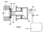
- Figure 1 shows an air connector 10 mounted opposite an intake port 120 leading in the direction of the arrow to an intake valve of an engine cylinder to allow the intake port 120 to communicate selectively with the intake pipe outside the intake port 120 and with a compressed air storage tank 40.
- the connector 10 comprises a stopper 12 mounted on a rod 14 movable by an actuator 30 between an open position in which the intake port 120 communicates with the intake pipe and a closed position in which the stopper 12 seals around the entrance of the intake port 120 to isolate the intake port 120 from the intake pipe.
- the stopper 12 is pushed by the actuator 30 towards the entrance of the intake port 120 and pressed against a sealing element 122 surrounding the port entrance with a sufficient force to hold a tight seal around the port entrance.
- An air passage 16 is provided in the stopper 12 and the rod 14 to allow communication between the intake port 120 and the compressed air storage tank 40 when the stopper 12 is in the closed position.
- a check valve 18 arranged in the air passage 16 is biased in a direction to prevent escape of air from the compressed air storage tank 40 in all positions of the stopper 12.
- the actuator 30 is a pneumatic actuator comprising a pneumatic air cylinder 32 connectable to receive compressed air from the compressed air storage tank 40, and a piston 34 having an opening 36 communicating between the air passage 16 in the rod 14 and the pneumatic air cylinder 32.
- the piston 34 is shown sealed for movement along the pneumatic air cylinder 32 by an O-ring. Alternatively it may be sealed for movement by a flexible diaphragm.
- the piston 34 has an effective area larger than the air blockage area of the stopper 12 such that the closing force exerted on the piston 34 by the air pressure in the pneumatic air cylinder 32 exceeds the opening force exerted on the stopper 12 by the air pressure transmitted to or generated within the blocked intake port 120.
- the actuator 30 further comprises a return spring 38 to retract the stopper 12 from the entrance of the intake port 120 when the pneumatic air cylinder 32 is disconnected from the compressed air storage tank 40 and vented instead to the ambient atmosphere.
- the check valve 18 includes a spring biased valve closure member operative to interact with an externally mounted abutment 124 to allow air flow in both directions when the stopper 12 is in the closed position.
- the abutment 124 is shown in Figure 1a as a bar mounted across the sealing element 122 for stopping and lifting the check valve 18 as the stopper 12 approaches the sealing element 122 when it is pushed by the actuator 30 towards the entrance of the intake port 120.
- Figure 2 shows an alternative design of an air connector 20 with a larger stopper 22 for blocking a larger intake port 220.
- the stopper 22 has additional flow passages 24 in an area surrounding the rod for connecting the air space outside the intake port 220 with the interior of the intake port 220 when the stopper 22 is in the closed position.
- a disc 26, positioned behind the flow passages 24, is arranged to function as a non-return valve which permits air flow from the intake pipe into the intake port 220 by way of the flow passages 24 and a central opening in the disc 26, and blocks any reverse flow from the intake port 220 towards the intake pipe.
- the above air connector 10 or 20 may be used in an internal combustion engine in a variety of operating modes.
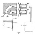
- Figure 3 shows a cylinder 110 of a four-stroke internal combustion engine.
- the piston 112 reciprocates within the cylinder 110 to define a variable volume working chamber.
- the working chamber has two intake valves 118a, 118b. It also has an exhaust valve (not shown) and all the valves operate in a conventional manner.
- the air supply to the engine is ducted along an intake plenum in the direction of the flow arrows.
- Intake ports 120a, 120b lead to the respective intake valves 118a, 118b and each port has a respective air connector 10a, 10b similar to that shown in Figure 1 mounted opposite the port entrances.
- the engine in addition to a normal mode of operation as shown in Figure 3 in which fuel is burnt to generate power and both air connectors are in the open position so that the intake ports 120a, 120b communicate with the intake plenum, the engine is operable in at least one of two air hybrid modes, namely an air compressor mode shown in Figure 4 and an air motor mode shown in Figure 5 .
- the engine operates in an air compressor mode in which air is drawn into the engine cylinder 110 during the intake stroke of the engine by way of the first intake port 120a with the air connector 10a in the open position, and this air is compressed and supplied by way of the second intake port 120b which is connected by the air connector 10b to the compressed air storage tank 40 during the ensuing compression stroke of the engine.
- the engine operates in an air motor mode in which compressed air is supplied by way of the first intake port 120a which is connected by the air connector 10a working in conjunction with an externally mounted abutment to permit air flow from the compressed air storage tank 40 to the engine cylinder 110 during the intake stroke of the engine, and this air is discharged from the engine cylinder 110 during the ensuing compression stroke of the engine by way of the second intake port 120b with the air connector 10b in the open position.
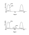
- the valve events of the above engine are shown in Figures 8 and 9 .
- the first intake valve 118a is operated with a normal intake event 136a shown in Figures 8 and 9 during all modes of operation of the engine and the second intake valve 118b is operated with a first valve event 136b shown in Figure 8 during the normal mode of operation of the engine and with a second valve event 136b shown in Figure 9 during the air compressor and air motor modes of operation of the engine.
- the above engine is also operable in another temporary boost, fuel burning mode for example to compensate for turbo lag or to provide short periods of high power operation.
- both air connectors 10a, 10b are in the closed position. Pressurised air is supplied to the engine cylinder 110 by way of the first intake port 120a which is connected to the compressed air storage tank 40 by the air connector 10a working in conjunction with an externally mounted abutment, while both intake valves 118a, 118b are operated with the valve events 136a, 136b for normal mode of operation of the engine shown in Figure 8 .
- the air connector 10b blocks the second intake port 120b and prevents escape of pressurised air to the intake plenum even though the second intake valve 118b is open during the intake stroke of the engine.
- Figure 7 shows another four-stroke internal combustion engine having two intake valves 218a, 218b sharing a common or siamesed intake port 220.
- the intake port 220 has an air connector 20 similar to that shown in Figure 2 mounted opposite the port entrance.
- the engine in addition to a normal mode of operation (not shown in Figure 7 ) in which fuel is burnt to generate power and the air connector 20 is in the open position so that the intake ports 220 communicates with the intake plenum, the engine is also operable in an air compressor mode with the air connector 20 in the closed position shown in Figure 7 .
- the engine operates in an air compressor mode in which air is drawn into the engine cylinder 210 during the intake stroke of the engine from the intake plenum by way of the non-return valve in the air connector 20, and this air is compressed and supplied by way of the check valve in the air connector 20 to the compressed air storage tank 40 during the ensuing compression stroke of the engine.
- the first intake valve 118a is operated with a normal intake event 136a shown in Figures 8 and 9 during all modes of operation of the engine and the second intake valve 118b is operated with a first valve event 136b shown in Figure 8 during the normal mode of operation of the engine and with a second valve event 136b shown in Figure 9 during the air compressor mode of operation of the engine.
- the above engine is also operable in another temporary boost, fuel burning mode for example to compensate for turbo lag or to provide short periods of high power operation.
- an air connector 10 or air connector 20 is mounted opposite the intake port 220 and in the closed position. Pressurised air is supplied to the engine cylinder 210 by way of the intake port 220 which is connected to the compressed air storage tank 40 by the air connector 10 or 20 working in conjunction with an externally mounted abutment, while both intake valves 218a, 218b are operated with the valve events for normal mode of operation of the engine.
Landscapes
- Engineering & Computer Science (AREA)
- Mechanical Engineering (AREA)
- Chemical & Material Sciences (AREA)
- Combustion & Propulsion (AREA)
- General Engineering & Computer Science (AREA)
- Transportation (AREA)
- Output Control And Ontrol Of Special Type Engine (AREA)
- Compressors, Vaccum Pumps And Other Relevant Systems (AREA)
- Supercharger (AREA)
- Exhaust Silencers (AREA)
Claims (7)
- Interner Verbrennungsmotor zur Verwendung in einem Fahrzeug mit einem Druckluftvorratsbehälter (40), wobei der Motor Einlass- und Abgaskanäle (120) aufweist, die mit zugehörigen Einlass- und Abgasrohren verbunden sind, gekennzeichnet durch einen Luftanschluss (10), der dazu dient, dass der Behälter mit durch den Motor erzeugtem Druckgas gefüllt werden kann, wobei der Luftanschluss (10) gegenüber von einem Einlass- oder Abgaskanal (120) innerhalb eines zugehörigen Einlass- oder Abgasohres befestigt ist und einen Stopper (12) umfasst, der an einer Stange (14) befestigt ist, die mit einem Luftdurchlass (16) geformt ist, der ein Rückschlagventil (18) umfasst, wobei der Stopper (12) während der Verwendung des Luftanschlusses (10) über einen Aktor (30) zwischen einer Offenstellung, in welcher der Kanal (120) mit dem zugehörigen Einlass- oder Abgasrohr kommuniziert und einer Schließstellung bewegt werden kann, in welcher der Stopper (12) den Kanal (120) von dem zugehörigen Einlass- oder Abgasrohr isoliert und er stellt über den Luftdurchlass (16) in der Stange (14) und das Rückschlagventil (18) eine Kommunikation zwischen dem Kanal (120) und dem Behälter (40) her, wobei das Rückschlagventil (18) in einer Richtung vorgespannt ist, um das Entweichen von Luft aus dem Behälter (40) zu verhindern.
- Interner Verbrennungsmotor nach Anspruch 1, wobei der Aktor (30) ein pneumatischer Aktor ist, der einen pneumatischen Druckluftzylinder (32), der verbunden werden kann, um Druckluft aus dem Druckluftvorratsbehälter (40) aufzunehmen und einen Kolben (34) umfasst, der eine Öffnung (36) aufweist und zwischen dem Luftdurchlass (16) in der Stange (14) und dem pneumatischen Druckluftzylinder (32) kommuniziert, wobei der Kolben (34) eine effektive Fläche aufweist, die größer als der Luftstaubereich des Stoppers (12) ist, sodass die Schließkraft, die auf den Kolben (34) durch den Luftdruck in dem pneumatischen Druckluftzylinder (32) ausgeübt wird, die Öffnungskraft übersteigt, die auf den Stopper (12) durch den Luftdruck ausgeübt wird, der an den gesperrten Kanal (120) übertragen oder in diesem generiert wird.
- Interner Verbrennungsmotor nach Anspruch 2, ferner umfassend eine Rückholfeder (38), um den Stopper (12) von dem Kanaleingang zurückzuholen, wenn der pneumatische Druckluftzylinder (32) von dem Druckluftvorratsbehälter (40) getrennt und stattdessen an die Umgebungsatmosphäre entlüftet wird.
- Interner Verbrennungsmotor nach einem der vorhergehenden Ansprüche, wobei das Rückschlagventil (18) ein federgespanntes Ventilverschlussglied umfasst, dass betrieben werden kann, um mit einem extern befestigten Abutment zu interagieren, um den Luftstrom in beide Richtungen zuzulassen, wenn sich der Stopper in der Schließstellung befindet.
- Interner Verbrennungsmotor nach einem der vorhergehenden Ansprüche, wobei mindestens ein Rückschlagventil in einem Bereich des Stoppers bereitgestellt wird, welcher die Stange umgibt, um den Luftstrom zwischen dem Kanal und dem zugehörigen Rohr zuzulassen, wenn sich der Stopper in der Schließstellung befindet.
- Interner Verbrennungsmotor nach einem der vorhergehenden Ansprüche, wobei der Motor ein Viertaktmotor mit zwei separaten Einlasskanälen pro Zylinder ist, die zu jeweiligen Einlassventilen führen und wobei ein Luftanschluss in einem Einlassrohr oder Einlassplenum gegenüber mindestens eines der Einlasskanäle jedes Zylinders befestigt ist.
- Interner Verbrennungsmotor nach einem der Ansprüche 1 bis 5, wobei der Motor ein Viertaktmotor mit einem einzelnen Einlasskanal pro Zylinder ist, der zu einem oder mehreren Einlassventilen führt, wobei ein Luftanschluss in einem Einlassrohr oder Einlassplenum gegenüber des Einlasskanals jedes Zylinders befestigt ist.
Priority Applications (1)
| Application Number | Priority Date | Filing Date | Title |
|---|---|---|---|
| PL11785488T PL2616652T3 (pl) | 2010-11-03 | 2011-11-02 | Przyłącze powietrza do silnika o spalaniu wewnętrznym |
Applications Claiming Priority (2)
| Application Number | Priority Date | Filing Date | Title |
|---|---|---|---|
| GB1018563.5A GB2485176A (en) | 2010-11-03 | 2010-11-03 | Air Connector for an Internal Combustion Engine and a Compressed Air Storage Tank |
| PCT/IB2011/054853 WO2012059865A1 (en) | 2010-11-03 | 2011-11-02 | Air connector for an internal combustion engine |
Publications (2)
| Publication Number | Publication Date |
|---|---|
| EP2616652A1 EP2616652A1 (de) | 2013-07-24 |
| EP2616652B1 true EP2616652B1 (de) | 2015-09-02 |
Family
ID=43401721
Family Applications (1)
| Application Number | Title | Priority Date | Filing Date |
|---|---|---|---|
| EP11785488.5A Not-in-force EP2616652B1 (de) | 2010-11-03 | 2011-11-02 | Luftanschluss für einen verbrennungsmotor |
Country Status (9)
| Country | Link |
|---|---|
| US (1) | US9032912B2 (de) |
| EP (1) | EP2616652B1 (de) |
| CN (1) | CN103201479B (de) |
| BR (1) | BR112013010732B1 (de) |
| ES (1) | ES2552980T3 (de) |
| GB (1) | GB2485176A (de) |
| PL (1) | PL2616652T3 (de) |
| PT (1) | PT2616652E (de) |
| WO (1) | WO2012059865A1 (de) |
Families Citing this family (3)
| Publication number | Priority date | Publication date | Assignee | Title |
|---|---|---|---|---|
| DE102013215851A1 (de) * | 2013-08-12 | 2015-02-12 | Bayerische Motoren Werke Aktiengesellschaft | Luftfederungsvorrichtung für ein Fahrzeug mit einem Verbrennungsmotor |
| US20160024993A1 (en) * | 2014-07-23 | 2016-01-28 | Paccar Inc | Compressed air supply method |
| US9522738B2 (en) * | 2015-04-23 | 2016-12-20 | Goodrich Corporation | Soft cover release mechanism for evacuation slides |
Family Cites Families (15)
| Publication number | Priority date | Publication date | Assignee | Title |
|---|---|---|---|---|
| US1132393A (en) | 1913-09-09 | 1915-03-16 | Earl T Schmucker | Convertible motor and pump. |
| US2995890A (en) * | 1957-05-31 | 1961-08-15 | Gen Motors Corp | Starting, accelerating and braking mechanism for an internal combustion engine |
| DE3117143C2 (de) | 1981-04-30 | 1984-01-12 | Heinz 7128 Lauffen Denz | Brennkraftmaschine |
| FR2831606B1 (fr) | 2001-10-31 | 2004-05-14 | Peugeot Citroen Automobiles Sa | Systeme de motorisation pour vehicule |
| FR2833650B1 (fr) * | 2001-12-14 | 2004-12-24 | Peugeot Citroen Automobiles Sa | Systeme de motorisation pour vehicule automobile |
| US6829892B2 (en) * | 2003-02-05 | 2004-12-14 | International Truck Intellectual Property Company, Llc | Engine exhaust system pneumatic pump |
| US7050900B2 (en) * | 2004-02-17 | 2006-05-23 | Miller Kenneth C | Dynamically reconfigurable internal combustion engine |
| US7231998B1 (en) | 2004-04-09 | 2007-06-19 | Michael Moses Schechter | Operating a vehicle with braking energy recovery |
| US7263970B2 (en) * | 2005-01-21 | 2007-09-04 | Honda Motor Co., Ltd. | Intake flow control apparatus for an internal combustion engine |
| GB0520545D0 (en) * | 2005-10-08 | 2005-11-16 | Ma Thomas T H | Energy control valve for air hybrid engine |
| WO2007058524A1 (en) * | 2005-11-18 | 2007-05-24 | De Gooijer Autotechniek B.V. | Internal combustion engine, vehicle and a method of operating them |
| JP4602300B2 (ja) | 2006-09-14 | 2010-12-22 | 本田技研工業株式会社 | 内燃機関における補機配置構造 |
| US7464675B1 (en) * | 2006-11-01 | 2008-12-16 | Michael Moses Schechter | Operating an air-hybrid vehicle with camshaft-driven engine valves |
| DE102007027968A1 (de) * | 2007-06-19 | 2009-01-02 | Knorr-Bremse Systeme für Nutzfahrzeuge GmbH | Verfahren und Vorrichtung zum Steigern der Motorbremsleistung einer Hubkolben-Verbrennungsmaschine eines Fahrzeugs, insbesondere eines Motors in Dieselausführung |
| WO2011015336A1 (de) * | 2009-08-03 | 2011-02-10 | Eth Zurich | Turboaufgeladene hubkolbenkraftmaschine mit angeschlossenem drucktank zur turbolochüberbrückung und verfahren zum betrieb derselben |
-
2010
- 2010-11-03 GB GB1018563.5A patent/GB2485176A/en not_active Withdrawn
-
2011
- 2011-11-02 EP EP11785488.5A patent/EP2616652B1/de not_active Not-in-force
- 2011-11-02 BR BR112013010732-4A patent/BR112013010732B1/pt not_active IP Right Cessation
- 2011-11-02 PT PT117854885T patent/PT2616652E/pt unknown
- 2011-11-02 ES ES11785488.5T patent/ES2552980T3/es active Active
- 2011-11-02 US US13/883,062 patent/US9032912B2/en not_active Expired - Fee Related
- 2011-11-02 PL PL11785488T patent/PL2616652T3/pl unknown
- 2011-11-02 CN CN201180053082.0A patent/CN103201479B/zh not_active Expired - Fee Related
- 2011-11-02 WO PCT/IB2011/054853 patent/WO2012059865A1/en not_active Ceased
Also Published As
| Publication number | Publication date |
|---|---|
| BR112013010732A2 (pt) | 2018-05-08 |
| WO2012059865A1 (en) | 2012-05-10 |
| CN103201479B (zh) | 2015-08-19 |
| GB2485176A (en) | 2012-05-09 |
| CN103201479A (zh) | 2013-07-10 |
| EP2616652A1 (de) | 2013-07-24 |
| BR112013010732B1 (pt) | 2020-12-08 |
| GB201018563D0 (en) | 2010-12-15 |
| PT2616652E (pt) | 2015-11-25 |
| US20130255595A1 (en) | 2013-10-03 |
| ES2552980T3 (es) | 2015-12-03 |
| PL2616652T3 (pl) | 2016-01-29 |
| US9032912B2 (en) | 2015-05-19 |
Similar Documents
| Publication | Publication Date | Title |
|---|---|---|
| CN101970827B (zh) | 用于空气混合动力汽车的发动机 | |
| US6006732A (en) | Balanced flow EGR control apparatus | |
| EP1627138A1 (de) | Brennkraftmaschine mit mehreren betriebsarten einschliesslich ein betrieb mit pressluft | |
| EP2232021B1 (de) | Druckluftsystem zur steuerung der ventile eines verbrennungsmotors | |
| BR112014006435A2 (pt) | método e sistema para descompressão de cilindro do motor | |
| US20110108013A1 (en) | Exhaust gas recirculation valve with bypass capability and method | |
| US9032912B2 (en) | Air connector for an internal combustion engine | |
| KR101935063B1 (ko) | 차량의 압축기를 위한 공기 공급을 제어하기 위한 밸브 장치, 압축기 시스템 및 압축기 시스템을 제어하기 위한 방법 | |
| EP1979584A1 (de) | Verfahren und vorrichtung zum betrieb eines ventils in der brennkammer eines verbrennungsmotors und verbrennungsmotor | |
| US10344683B2 (en) | Combustion engine as well as method for engine braking using such a combustion engine | |
| CN102165148A (zh) | 电动液压的气门控制装置 | |
| CN101963090B (zh) | 横跨气门系统 | |
| US7735518B2 (en) | Valve assembly with dual actuation solenoids | |
| EP1960641B1 (de) | Abgassteuervorrichtung | |
| CN205654389U (zh) | 一种压电驱动的无凸轮轴气门驱动机构 | |
| GB2464704A (en) | Air motor | |
| JP2004518845A (ja) | 内燃機関用のガス交換弁装置 | |
| CN206625896U (zh) | 发动机系统及应用该发动机系统的汽车 | |
| JP5526853B2 (ja) | ダイヤフラム型アクチュエータ | |
| US6006733A (en) | Exhaust gas recirculation apparatus | |
| CN101397921B (zh) | 气动发动机电气驱动全可变气门机构 | |
| US10072653B2 (en) | Device for conserving power in a piston compressor | |
| JPH0144723Y2 (de) | ||
| CN202834327U (zh) | 气动压缩天然气瓶阀 | |
| JP7026679B2 (ja) | トルクを増大させる装置を備える往復動内燃機関 |
Legal Events
| Date | Code | Title | Description |
|---|---|---|---|
| PUAI | Public reference made under article 153(3) epc to a published international application that has entered the european phase |
Free format text: ORIGINAL CODE: 0009012 |
|
| 17P | Request for examination filed |
Effective date: 20130415 |
|
| AK | Designated contracting states |
Kind code of ref document: A1 Designated state(s): AL AT BE BG CH CY CZ DE DK EE ES FI FR GB GR HR HU IE IS IT LI LT LU LV MC MK MT NL NO PL PT RO RS SE SI SK SM TR |
|
| DAX | Request for extension of the european patent (deleted) | ||
| 17Q | First examination report despatched |
Effective date: 20140212 |
|
| GRAP | Despatch of communication of intention to grant a patent |
Free format text: ORIGINAL CODE: EPIDOSNIGR1 |
|
| INTG | Intention to grant announced |
Effective date: 20150319 |
|
| GRAS | Grant fee paid |
Free format text: ORIGINAL CODE: EPIDOSNIGR3 |
|
| GRAR | Information related to intention to grant a patent recorded |
Free format text: ORIGINAL CODE: EPIDOSNIGR71 |
|
| GRAA | (expected) grant |
Free format text: ORIGINAL CODE: 0009210 |
|
| AK | Designated contracting states |
Kind code of ref document: B1 Designated state(s): AL AT BE BG CH CY CZ DE DK EE ES FI FR GB GR HR HU IE IS IT LI LT LU LV MC MK MT NL NO PL PT RO RS SE SI SK SM TR |
|
| INTG | Intention to grant announced |
Effective date: 20150728 |
|
| REG | Reference to a national code |
Ref country code: GB Ref legal event code: FG4D |
|
| REG | Reference to a national code |
Ref country code: AT Ref legal event code: REF Ref document number: 746770 Country of ref document: AT Kind code of ref document: T Effective date: 20150915 Ref country code: CH Ref legal event code: EP |
|
| REG | Reference to a national code |
Ref country code: IE Ref legal event code: FG4D |
|
| REG | Reference to a national code |
Ref country code: DE Ref legal event code: R096 Ref document number: 602011019439 Country of ref document: DE |
|
| REG | Reference to a national code |
Ref country code: FR Ref legal event code: PLFP Year of fee payment: 5 |
|
| REG | Reference to a national code |
Ref country code: PT Ref legal event code: SC4A Free format text: AVAILABILITY OF NATIONAL TRANSLATION Effective date: 20151111 |
|
| REG | Reference to a national code |
Ref country code: SE Ref legal event code: TRGR |
|
| REG | Reference to a national code |
Ref country code: ES Ref legal event code: FG2A Ref document number: 2552980 Country of ref document: ES Kind code of ref document: T3 Effective date: 20151203 |
|
| REG | Reference to a national code |
Ref country code: AT Ref legal event code: MK05 Ref document number: 746770 Country of ref document: AT Kind code of ref document: T Effective date: 20150902 |
|
| REG | Reference to a national code |
Ref country code: NL Ref legal event code: FP |
|
| PG25 | Lapsed in a contracting state [announced via postgrant information from national office to epo] |
Ref country code: FI Free format text: LAPSE BECAUSE OF FAILURE TO SUBMIT A TRANSLATION OF THE DESCRIPTION OR TO PAY THE FEE WITHIN THE PRESCRIBED TIME-LIMIT Effective date: 20150902 Ref country code: LV Free format text: LAPSE BECAUSE OF FAILURE TO SUBMIT A TRANSLATION OF THE DESCRIPTION OR TO PAY THE FEE WITHIN THE PRESCRIBED TIME-LIMIT Effective date: 20150902 Ref country code: GR Free format text: LAPSE BECAUSE OF FAILURE TO SUBMIT A TRANSLATION OF THE DESCRIPTION OR TO PAY THE FEE WITHIN THE PRESCRIBED TIME-LIMIT Effective date: 20151203 Ref country code: LT Free format text: LAPSE BECAUSE OF FAILURE TO SUBMIT A TRANSLATION OF THE DESCRIPTION OR TO PAY THE FEE WITHIN THE PRESCRIBED TIME-LIMIT Effective date: 20150902 Ref country code: NO Free format text: LAPSE BECAUSE OF FAILURE TO SUBMIT A TRANSLATION OF THE DESCRIPTION OR TO PAY THE FEE WITHIN THE PRESCRIBED TIME-LIMIT Effective date: 20151202 |
|
| REG | Reference to a national code |
Ref country code: LT Ref legal event code: MG4D |
|
| PG25 | Lapsed in a contracting state [announced via postgrant information from national office to epo] |
Ref country code: RS Free format text: LAPSE BECAUSE OF FAILURE TO SUBMIT A TRANSLATION OF THE DESCRIPTION OR TO PAY THE FEE WITHIN THE PRESCRIBED TIME-LIMIT Effective date: 20150902 Ref country code: AT Free format text: LAPSE BECAUSE OF FAILURE TO SUBMIT A TRANSLATION OF THE DESCRIPTION OR TO PAY THE FEE WITHIN THE PRESCRIBED TIME-LIMIT Effective date: 20150902 |
|
| PG25 | Lapsed in a contracting state [announced via postgrant information from national office to epo] |
Ref country code: CZ Free format text: LAPSE BECAUSE OF FAILURE TO SUBMIT A TRANSLATION OF THE DESCRIPTION OR TO PAY THE FEE WITHIN THE PRESCRIBED TIME-LIMIT Effective date: 20150902 Ref country code: IS Free format text: LAPSE BECAUSE OF FAILURE TO SUBMIT A TRANSLATION OF THE DESCRIPTION OR TO PAY THE FEE WITHIN THE PRESCRIBED TIME-LIMIT Effective date: 20160102 Ref country code: SK Free format text: LAPSE BECAUSE OF FAILURE TO SUBMIT A TRANSLATION OF THE DESCRIPTION OR TO PAY THE FEE WITHIN THE PRESCRIBED TIME-LIMIT Effective date: 20150902 Ref country code: EE Free format text: LAPSE BECAUSE OF FAILURE TO SUBMIT A TRANSLATION OF THE DESCRIPTION OR TO PAY THE FEE WITHIN THE PRESCRIBED TIME-LIMIT Effective date: 20150902 |
|
| REG | Reference to a national code |
Ref country code: DE Ref legal event code: R082 Ref document number: 602011019439 Country of ref document: DE Representative=s name: HERNANDEZ, YORCK, DIPL.-ING., DE |
|
| PG25 | Lapsed in a contracting state [announced via postgrant information from national office to epo] |
Ref country code: RO Free format text: LAPSE BECAUSE OF FAILURE TO SUBMIT A TRANSLATION OF THE DESCRIPTION OR TO PAY THE FEE WITHIN THE PRESCRIBED TIME-LIMIT Effective date: 20150902 |
|
| REG | Reference to a national code |
Ref country code: DE Ref legal event code: R097 Ref document number: 602011019439 Country of ref document: DE |
|
| PG25 | Lapsed in a contracting state [announced via postgrant information from national office to epo] |
Ref country code: MC Free format text: LAPSE BECAUSE OF FAILURE TO SUBMIT A TRANSLATION OF THE DESCRIPTION OR TO PAY THE FEE WITHIN THE PRESCRIBED TIME-LIMIT Effective date: 20150902 Ref country code: LU Free format text: LAPSE BECAUSE OF FAILURE TO SUBMIT A TRANSLATION OF THE DESCRIPTION OR TO PAY THE FEE WITHIN THE PRESCRIBED TIME-LIMIT Effective date: 20151102 |
|
| REG | Reference to a national code |
Ref country code: CH Ref legal event code: PL |
|
| PLBE | No opposition filed within time limit |
Free format text: ORIGINAL CODE: 0009261 |
|
| STAA | Information on the status of an ep patent application or granted ep patent |
Free format text: STATUS: NO OPPOSITION FILED WITHIN TIME LIMIT |
|
| PG25 | Lapsed in a contracting state [announced via postgrant information from national office to epo] |
Ref country code: CH Free format text: LAPSE BECAUSE OF NON-PAYMENT OF DUE FEES Effective date: 20151130 Ref country code: LI Free format text: LAPSE BECAUSE OF NON-PAYMENT OF DUE FEES Effective date: 20151130 |
|
| 26N | No opposition filed |
Effective date: 20160603 |
|
| PG25 | Lapsed in a contracting state [announced via postgrant information from national office to epo] |
Ref country code: DK Free format text: LAPSE BECAUSE OF FAILURE TO SUBMIT A TRANSLATION OF THE DESCRIPTION OR TO PAY THE FEE WITHIN THE PRESCRIBED TIME-LIMIT Effective date: 20150902 Ref country code: SI Free format text: LAPSE BECAUSE OF FAILURE TO SUBMIT A TRANSLATION OF THE DESCRIPTION OR TO PAY THE FEE WITHIN THE PRESCRIBED TIME-LIMIT Effective date: 20150902 |
|
| REG | Reference to a national code |
Ref country code: FR Ref legal event code: PLFP Year of fee payment: 6 |
|
| PG25 | Lapsed in a contracting state [announced via postgrant information from national office to epo] |
Ref country code: HU Free format text: LAPSE BECAUSE OF FAILURE TO SUBMIT A TRANSLATION OF THE DESCRIPTION OR TO PAY THE FEE WITHIN THE PRESCRIBED TIME-LIMIT; INVALID AB INITIO Effective date: 20111102 Ref country code: SM Free format text: LAPSE BECAUSE OF FAILURE TO SUBMIT A TRANSLATION OF THE DESCRIPTION OR TO PAY THE FEE WITHIN THE PRESCRIBED TIME-LIMIT Effective date: 20150902 Ref country code: BG Free format text: LAPSE BECAUSE OF FAILURE TO SUBMIT A TRANSLATION OF THE DESCRIPTION OR TO PAY THE FEE WITHIN THE PRESCRIBED TIME-LIMIT Effective date: 20150902 |
|
| PG25 | Lapsed in a contracting state [announced via postgrant information from national office to epo] |
Ref country code: CY Free format text: LAPSE BECAUSE OF FAILURE TO SUBMIT A TRANSLATION OF THE DESCRIPTION OR TO PAY THE FEE WITHIN THE PRESCRIBED TIME-LIMIT Effective date: 20150902 |
|
| PG25 | Lapsed in a contracting state [announced via postgrant information from national office to epo] |
Ref country code: HR Free format text: LAPSE BECAUSE OF FAILURE TO SUBMIT A TRANSLATION OF THE DESCRIPTION OR TO PAY THE FEE WITHIN THE PRESCRIBED TIME-LIMIT Effective date: 20150902 |
|
| PG25 | Lapsed in a contracting state [announced via postgrant information from national office to epo] |
Ref country code: MT Free format text: LAPSE BECAUSE OF FAILURE TO SUBMIT A TRANSLATION OF THE DESCRIPTION OR TO PAY THE FEE WITHIN THE PRESCRIBED TIME-LIMIT Effective date: 20150902 |
|
| REG | Reference to a national code |
Ref country code: FR Ref legal event code: PLFP Year of fee payment: 7 |
|
| PG25 | Lapsed in a contracting state [announced via postgrant information from national office to epo] |
Ref country code: TR Free format text: LAPSE BECAUSE OF FAILURE TO SUBMIT A TRANSLATION OF THE DESCRIPTION OR TO PAY THE FEE WITHIN THE PRESCRIBED TIME-LIMIT Effective date: 20150902 Ref country code: MK Free format text: LAPSE BECAUSE OF FAILURE TO SUBMIT A TRANSLATION OF THE DESCRIPTION OR TO PAY THE FEE WITHIN THE PRESCRIBED TIME-LIMIT Effective date: 20150902 |
|
| PG25 | Lapsed in a contracting state [announced via postgrant information from national office to epo] |
Ref country code: AL Free format text: LAPSE BECAUSE OF FAILURE TO SUBMIT A TRANSLATION OF THE DESCRIPTION OR TO PAY THE FEE WITHIN THE PRESCRIBED TIME-LIMIT Effective date: 20150902 |
|
| PGFP | Annual fee paid to national office [announced via postgrant information from national office to epo] |
Ref country code: NL Payment date: 20181121 Year of fee payment: 8 |
|
| PGFP | Annual fee paid to national office [announced via postgrant information from national office to epo] |
Ref country code: LT Payment date: 20181217 Year of fee payment: 7 Ref country code: SE Payment date: 20181120 Year of fee payment: 8 Ref country code: PL Payment date: 20181019 Year of fee payment: 8 Ref country code: IE Payment date: 20181126 Year of fee payment: 8 |
|
| PGFP | Annual fee paid to national office [announced via postgrant information from national office to epo] |
Ref country code: FR Payment date: 20181120 Year of fee payment: 8 |
|
| REG | Reference to a national code |
Ref country code: SE Ref legal event code: EUG |
|
| REG | Reference to a national code |
Ref country code: NL Ref legal event code: MM Effective date: 20191201 |
|
| PG25 | Lapsed in a contracting state [announced via postgrant information from national office to epo] |
Ref country code: PT Free format text: LAPSE BECAUSE OF NON-PAYMENT OF DUE FEES Effective date: 20200604 |
|
| REG | Reference to a national code |
Ref country code: BE Ref legal event code: MM Effective date: 20191130 |
|
| PG25 | Lapsed in a contracting state [announced via postgrant information from national office to epo] |
Ref country code: SE Free format text: LAPSE BECAUSE OF NON-PAYMENT OF DUE FEES Effective date: 20191103 |
|
| PG25 | Lapsed in a contracting state [announced via postgrant information from national office to epo] |
Ref country code: NL Free format text: LAPSE BECAUSE OF NON-PAYMENT OF DUE FEES Effective date: 20191201 |
|
| PG25 | Lapsed in a contracting state [announced via postgrant information from national office to epo] |
Ref country code: FR Free format text: LAPSE BECAUSE OF NON-PAYMENT OF DUE FEES Effective date: 20191130 Ref country code: IE Free format text: LAPSE BECAUSE OF NON-PAYMENT OF DUE FEES Effective date: 20191102 |
|
| PG25 | Lapsed in a contracting state [announced via postgrant information from national office to epo] |
Ref country code: BE Free format text: LAPSE BECAUSE OF NON-PAYMENT OF DUE FEES Effective date: 20191130 |
|
| REG | Reference to a national code |
Ref country code: ES Ref legal event code: FD2A Effective date: 20210527 |
|
| PG25 | Lapsed in a contracting state [announced via postgrant information from national office to epo] |
Ref country code: ES Free format text: LAPSE BECAUSE OF NON-PAYMENT OF DUE FEES Effective date: 20191103 |
|
| PGFP | Annual fee paid to national office [announced via postgrant information from national office to epo] |
Ref country code: DE Payment date: 20211109 Year of fee payment: 11 Ref country code: GB Payment date: 20211011 Year of fee payment: 11 |
|
| PG25 | Lapsed in a contracting state [announced via postgrant information from national office to epo] |
Ref country code: PL Free format text: LAPSE BECAUSE OF NON-PAYMENT OF DUE FEES Effective date: 20191102 |
|
| PGFP | Annual fee paid to national office [announced via postgrant information from national office to epo] |
Ref country code: IT Payment date: 20211105 Year of fee payment: 11 |
|
| REG | Reference to a national code |
Ref country code: DE Ref legal event code: R119 Ref document number: 602011019439 Country of ref document: DE |
|
| GBPC | Gb: european patent ceased through non-payment of renewal fee |
Effective date: 20221102 |
|
| PG25 | Lapsed in a contracting state [announced via postgrant information from national office to epo] |
Ref country code: IT Free format text: LAPSE BECAUSE OF NON-PAYMENT OF DUE FEES Effective date: 20221102 Ref country code: GB Free format text: LAPSE BECAUSE OF NON-PAYMENT OF DUE FEES Effective date: 20221102 Ref country code: DE Free format text: LAPSE BECAUSE OF NON-PAYMENT OF DUE FEES Effective date: 20230601 |