EP2614742B1 - Reissverschluss - Google Patents
Reissverschluss Download PDFInfo
- Publication number
- EP2614742B1 EP2614742B1 EP13001893.0A EP13001893A EP2614742B1 EP 2614742 B1 EP2614742 B1 EP 2614742B1 EP 13001893 A EP13001893 A EP 13001893A EP 2614742 B1 EP2614742 B1 EP 2614742B1
- Authority
- EP
- European Patent Office
- Prior art keywords
- row
- portions
- slide fastener
- elements
- fastener
- Prior art date
- Legal status (The legal status is an assumption and is not a legal conclusion. Google has not performed a legal analysis and makes no representation as to the accuracy of the status listed.)
- Active
Links
Images


Classifications
-
- A—HUMAN NECESSITIES
- A44—HABERDASHERY; JEWELLERY
- A44B—BUTTONS, PINS, BUCKLES, SLIDE FASTENERS, OR THE LIKE
- A44B19/00—Slide fasteners
- A44B19/02—Slide fasteners with a series of separate interlocking members secured to each stringer tape
- A44B19/04—Stringers arranged edge-to-edge when fastened, e.g. abutting stringers
- A44B19/06—Stringers arranged edge-to-edge when fastened, e.g. abutting stringers with substantially rectangular members having interlocking projections and pieces
-
- A—HUMAN NECESSITIES
- A44—HABERDASHERY; JEWELLERY
- A44B—BUTTONS, PINS, BUCKLES, SLIDE FASTENERS, OR THE LIKE
- A44B19/00—Slide fasteners
- A44B19/24—Details
- A44B19/26—Sliders
Definitions
- the invention relates to a slide fastener in which, for example, in a case where a slide fastener is used to open or close right and left front bodies of clothing, elements capable of aesthetically finishing an appearance of a slide fastener front surface shown at a front side of corresponding clothing are lined.
- a three-dimensional slide fastener has been known in which elements in which a protruding edge capable of increasing the lateral pulling strength in a width direction (a right-left direction) of the slide fastener and a fitting groove engaged to the protruding edge are formed are lined, and when engaging left and right elements to each other, left and right element rows are introduced from left and right shoulder mouths of a slider at different front-back levels, and the left and right element rows are obliquely joined and engaged from a front-back direction and a left-right direction (for example, see Patent Documents 2 and 3).
- the surface of an element is formed in the shape of goods or a logo mark, and it has a design that attracts a user's attention when enlarged and viewed.
- the long side of each of elements of the slide fastener has the size of about 3 mm to 5 mm.
- gaps between the elements are alternately dotted at both sides of the left and right element rows as spaces.
- the presence of the spaces dotted in the left and right element rows has constantly appealed the presence of the slide fastener in an appearance of goods such as clothing, bags, or the like.
- the invention is made to improve the above described conventional art and aims to provide a slide fastener in which a sense of the presence of left and right element rows that are in an engaging state is reduced, and elements capable of finishing an appearance aesthetically are lined.
- a slide fastener includes: a first element row fixed to one side edge of a fastener tape in a first fastener stringer; a second element row fixed to one side edge of a second fastener stringer; and a slider including an element guide passage that allows the first element row and the second element row arranged to face each other to pass through and performs engaging and disengaging, wherein in a case where one surface of a direction vertical to fastener tape surfaces of the first and second fastener stringers is defined as a front surface, and another surface is defined as a back surface, elements of the first element row and the second element row include element body portions from which a pair of front and back fixing leg portions fixed to the fastener stringers are extended, engagement neck portions that extend toward opposing elements row sides from the element body portions, engagement head portions that are swollen toward forefronts further from the engagement neck portions, front latch portions that extend toward opposing elements row sides from front surface sides of the element body portions, and back latch portions formed on front
- front surface sides of the first element row and the second element row have a rectangular shape.
- front surface sides of the first element row and the second element row have a plane shape.
- the extension length of the front latch portion formed in the first element row fixed to the opposing side edge of the first fastener stringer is formed to be shorter than the extension length of the front latch portion formed in the second element row fixed to the opposing side edge of the second fastener stringer.
- the front surface sides of the first element row and the second element row in the rectangular shape, it is possible to finish with an appearance that is difficult to be reminiscent of the elements of the slide fastener.
- the decoration surface in which a concave convex shape, an engraving, or a pattern is formed on the front surface side, or colorization such as gradation is performed on the front surface side the element row of the slide fastener can be used as a part of decorations of goods such as clothing, bags, or the like. Further, an appearance of goods can be more aesthetically finished.
- the front surface sides of the first element row and the second element row have the plane shape, post processing such as inkjet printing, film sticking, thermal transfer of patterns or the like, engraving, laser processing, or the like can be easily performed.
- post processing such as inkjet printing, film sticking, thermal transfer of patterns or the like, engraving, laser processing, or the like can be easily performed.
- the slide fastener with more fine and clear pattern or logo mark can be provided at a low cost.
- FIG. 1 is a plane view in which a slide fastener according to the invention is viewed from the front side and is a view for explaining a state in which element rows that are in a disengaging state in an upper part of the same drawing transition to an engaging state downward.
- FIG. 2 is a left side view of the slide fastener illustrated in FIG. 1 . Further, in FIGS. 1 and 2 , for conveniently describing the engaging state and the disengaging state of the element rows, a slider 50 is denoted by an imaginary line.
- a fastener tape plane of each of a first fastener stringer 16 and a second fastener stringer 17 is defined as an X-Y plane.
- a straight line of a longitudinal direction parallel to an engaging axial line is defined a Y axis, and a side at which the first element 12 row and the second element 13 row become the disengaging state and are opened is defined as a +Y direction.
- a left-right direction (a width direction) of the slide fastener 10 illustrated in FIG. 1 is defined as an X axis, a left side where the first fastener stringer 16 is present is defined as a -X direction, and a right side where the second fastener stringer 17 is present is defined as a +X direction.
- a front-back direction of each fastener tape in the slide fastener 10 is defined as a Z axis.
- a surface on which a decoration surface 12F in the first element 12 and a decoration surface 13F in the second element 13 row are formed, respectively, is defined as a front surface of the slide fastener 10, and a front surface side of the slide fastener 10 is defined as a +Z direction. Therefore, a back surface side of the slide fastener 10 becomes a -Z direction.
- the slide fastener 10 is an opening/closing device for opening/closing left and right front bodies of outer clothes or an opening of bags or the like.
- core portions 14 that are swollen in the front-back direction of the fastener tape along corresponding side edge portions are formed in opposing side edge portions of the first fastener stringer 16 and the second fastener stringer 17 of left and right that configure the slide fastener 10.
- Left and right element rows are formed such that a plurality of first elements 12 and a plurality of second elements 13 are lined at a predetermined interval CR to sandwich the core portions 14.
- resin molding such as polyacetal may be used as a material of the first element 12 and the second element 13
- the front surfaces of the first element 12 and the second element 13 may be formed in a rectangular shape. Further, it is possible to narrow the interval CR between the elements in the first element 12 row and the second element 13 row. As described above, an occupied area of the elements in the engaging state can increase by forming the front surfaces of the first element 12 and the second element 13 in the rectangular shape or narrowing the interval CR between the elements. Thus, it is possible to obtain an appearance that reduces a sense of the presence of the slide fastener 10 to the user.
- the slide fastener 10 includes the slider 50 that allows the first element 12 row and the second element 13 row to pass though and makes an upward opening possible.
- the slider 50 includes an upper blade piece 52 that guides the +Z side of the first element 12 row and the second element 13 row and a lower blade piece 53 that guides the -Z side of the first element 12 row and the second element 13 row.
- flanges 50F that join both elements from the left-right direction are extended at both side edge portions of the upper blade piece 52 and the lower blade piece 53 of the slider 50. Further, even though not illustrated in FIGS. 1 and 2 , tape grooves that allow the fastener tapes of the first fastener stringer 16 and the second fastener stringer 17 to pass through are formed at spindly gap portions where the flanges 50F extended to the upper blade piece 52 and the lower blade piece 53 are opposite to each other.
- an attaching post 56 is erected on the front surface of the +Z side of the upper blade piece 52 in the slider 50.
- a bearing hole 56A that rotatably holds a shaft portion of a tab 59 gripped by the user when moving the slider 50 in the ⁇ Y direction is opened at a central portion of the attaching post 56.
- an element guide passage 51 that allows the first element 12 row and the second element 13 row to pass through in the front-back direction of the slider 50 (the +Y direction and the -Y direction) is formed in the shape of a letter "Y" in a planar view in the form surrounded by the left and right flanges 50F.
- a connecting post 50D that connects the upper blade piece 52 with the lower blade piece 53 is arranged at an intermediate portion of a first shoulder mouth 50L and a second shoulder mouth 50R that are opened at the +Y side of the element guide passage 51. Since the connecting post 50D is formed in the shape of a sharp wedge toward the -Y side, by moving the slider 50 in the -Y direction, the first element 12 and the second element 13 that are in the engaging state can be disengaged in the left-right direction.
- the first shoulder mouth 50L is opened with a step difference at the -Z side of the back surface side further than the second shoulder mouth 50R.
- the first shoulder mouth 50L and the second shoulder mouth 50R introduce or discharge the first element 12 row and the second element 13 row of left and right that are in the disengaging state at different front-back levels.
- a front-back disengaging wall 50E for disengaging the first element 12 and the second element 13 of left and right that are in the engaging state in the front-back direction is formed inside the element guide passage 51.
- a rear mouth 50T is opened at the -Y side of the element guide passage 51.
- the rear mouth 50T introduces or discharges the first element 12 row and the second element 13 row of left and right that are engaged into the element guide passage 51.
- the slider 50 moves in the +Y direction.
- the first element 12 and the second element 13 row that are in the disengaging state are introduced at different front-back levels from the first shoulder mouth 50L and the second shoulder mouth 50R, respectively, and both element rows in the element guide passage 51 are obliquely joined from the front-back direction and the left-right direction and engaged to each other. Then, the first element 12 row and the second element 13 row that have become the engaging state are discharged from the rear mouth 50T.
- the slider 50 moves in the -Y direction.
- the first element 12 row and the second element 13 row that are in the engaging state are introduced through the rear mouth 50T of the slider 50, both element rows are disengaged in the front-back direction in the front-back disengaging wall 50E (see FIG. 2 ) formed in the element guide passage 51, and both element rows are obliquely disengaged in the left-right direction in the connecting post 50D (see FIG. 1 ) formed in the element guide passage 51.
- the first element 12 row and the second element 13 row that have become the disengaging state are discharged from the first shoulder mouth 50L and the second shoulder mouth 50R, respectively.
- FIG. 3 is a perspective view in which the slide fastener 10 in the engaging state is viewed from the +Z side (the front side)
- FIG. 4 is a perspective view viewed from the -Z side (the back side).
- the same members as the members illustrated in FIGS. 1 and 2 are denoted by the same reference numerals, and thus a description thereof will be omitted.
- decoration surfaces 12F and 13F of the +Z side of the first element 12 and the second element 13 have rectangular plane surfaces, and "ABC" is formed on the decoration surfaces 12F and 13F as a pattern.
- the pattern may be engraved on an element forming mold in advance or may be formed by post processing such as inkjet printing, film sticking, thermal transfer, engraving, laser processing, or the like.
- post processing such as inkjet printing, film sticking, thermal transfer, engraving, laser processing, or the like.
- the back surfaces of the -Z side of the first element 12 and the second element 13 have almost the same appearance as an element of resin molding that has been sold in the past.
- an appearance of the back surface in the slide fastener 10 is immediately pronounced of an element row by resin molding.
- an appearance of the decoration surfaces 12F and 13F of the first element 12 row and the second element 13 row illustrated in FIG. 3 is not immediately pronounced of the presence of the slide fastener 10.
- FIG. 5 is a front view in which the first element 12 is viewed toward the +Y side from the -Y side
- FIG. 6 is a back view viewed toward the +Z side (the front surface side) from the -Z side (the back surface side)
- FIG. 7 is a front view in which the second element 13 is viewed toward the +Y side from the -Y side
- FIG. 8 is a back view viewed toward the +Z side (the front surface side) from the -Z side (the back surface side).
- the same members as the members illustrated in FIGS. 1 to 4 are denoted by the same reference numerals, and thus a description thereof will be omitted.
- the first element 12 includes a pair of front fixing leg portion 12U and back fixing leg portion 12V of front and back that sandwich and fix the fastener tape and the core portion 14 of the first fastener stringer 16 from the front side and the back side, an element body portion 12B from which the front fixing leg portion 12U and the back fixing leg portion 12V are extended in the -X direction, an engagement neck portion 12N that extends toward the +X direction of the opposing second element 13 row side from the element body portion 12B, and an engagement head portion 12H that is swollen at a forefront side further than the engagement neck portion 12N.
- the engagement neck portion 12N is a portion in which a constriction is formed to hold the engagement head portions formed in the opposing two second elements 13 in the +Y and -Y sides.
- the engagement head portion 12H is a portion swollen to enter the engagement neck portions formed in the opposing two second elements 13.
- the engagement neck portion 12N and the engagement head portion 12H are an engaging portion for performing engaging that endures lateral pulling force of the left-right direction in a state in which the first fastener stringer 16 and the second fastener stringer 17 of left and right are closed.
- a front latch portion 12D that extends toward the +X direction of the second element 13 row side from the front surface side in the element body portion 12B of the first element 12 is formed toward the -Z side.
- the front latch portion 12D extends toward the +Z side of the engagement neck portion 12N and both of the +Y side and the -Y side of the engagement neck portion 12N.
- a back latch portion 12R facing the +Z direction is formed at the +Z side of the front surface side of the engagement neck portion 12N and the engagement head portion 12H.
- the back latch portion 12R is an engaging member that is engaged with the front latch portions formed in the opposing two second elements 13 and thus prevents engaging of the front-back direction from being deviated as the first element 12 in the engaging state moves on the second element 13 in the +Z direction.
- the front latch portion 12D is an engaging portion that is engaged with the back latch portions respectively formed in the opposing two second elements 13 and thus prevents engaging of the front-back direction from being deviated as the first element 12 in the engaging state moves on the second element 13 in the -Z direction.
- the front latch portion 12D and the back latch portion 12R in the first element 12, it is possible to perform engaging that endures shearing force of the front-back direction in a state in which the first fastener stringer 16 and the second fastener stringer 17 of left and right are closed.
- the front latch portion 12D extending toward the +X direction is formed to have a first extension length 12L shorter than an extension length of a front latch portion of the second element 13 which will be described later.
- the second element 13 includes a pair of front fixing leg portion 13U and back fixing leg portion 13V of front and back that sandwich and fix the fastener tape and the core portion 14 of the second fastener stringer 17 from the front side and the back side, an element body portion 13B from which the front fixing leg portion 13U and the back fixing leg portion 13V are extended in the +X direction, an engagement neck portion 13N that extends toward the -X direction of the opposing first element 12 row side from the element body portion 13B, and an engagement head portion 13H that is swollen at a forefront side further than the engagement neck portion 13N.
- the engagement neck portion 13N is a portion in which a constriction is formed to hold the engagement head portions 12H formed in the opposing two first elements 12 in the +Y and -Y sides.
- the engagement head portion 13H is a portion swollen to enter the engagement neck portions 12N formed in the opposing two first elements 12.
- the engagement neck portion 13N and the engagement head portion 13H are an engaging portion for performing engaging that endures lateral pulling force of the left-right direction in a state in which the first fastener stringer 16 and the second fastener stringer 17 of left and right are closed.
- a front latch portion 13D that extends toward the -X direction of the first element 12 row side from the front surface side in the element body portion 13B of the second element 13 is formed toward the -Z side.
- the front latch portion 13D extends toward the +Z side of the engagement neck portion 13N and both of the +Y side and the -Y side of the engagement neck portion 13N.
- a back latch portion 13R facing the +Z direction is formed at the +Z side of the front surface side of the engagement head portion 13H.
- the back latch portion 13R is an engaging member that is engaged with the front latch portions 12D formed in the opposing two first elements 12 and thus prevents engaging of the front-back direction from being deviated as the second element 13 in the engaging state moves on the first element 12 in the +Z direction.
- the front latch portion 13D is an engaging portion that is engaged with the back latch portions 12R respectively formed in the opposing two first elements 12 and thus prevents engaging of the front-back direction from being deviated as the second element 13 in the engaging state moves on the first element 12 in the -Z direction.
- the front latch portion 13D and the back latch portion 13R in the second element 13, it is possible to perform engaging that endures shearing force of the front-back direction in a state in which the first fastener stringer 16 and the second fastener stringer 17 of left and right are closed.
- the front latch portion 13D extending toward the -X direction is formed to have a second extension length 13L longer than the above described first extension length 12L of the front latch portion 12D of the first element 12.
- the long second extension length 13L of the front latch portion 13D as described above, it is possible to narrow the gap between the decoration surface 12F and the decoration surface 13F when the first element 12 row is engaged with the second element 13 row.
- the decorations portrayed on the decoration surface 12F and the decoration surface 13F is more continuously finished, and thus an appearance of the slide fastener 10 can be aesthetically finished.
- the long second extension length 13L of the front latch portion 13D it is possible to improve bearing force when thrust force is applied to the first element 12 row and the second element 13 row that are in the engaging state.
- FIG. 9 is a back view in which the engaging state of the left-right direction by the first element 12 row and the second element 13 row is viewed from the back surface side (the -Z side) of the slide fastener 10.
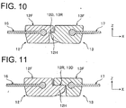
- FIGS. 10 and 11 are views in which the engaging state of the front-back direction by the first element 12 row and the second element 13 row is viewed from the -Y side.
- FIG. 10 is a cross-sectional view taken along line X-X illustrated in FIG. 9
- FIG. 11 is a cross-sectional view taken along line XI-XI illustrated in FIG. 9 .
- the engaging state of the left-right direction of the first element 12 row and the second element 13 row will be described with reference to FIG. 9 .
- the first element 12 holds the engagement head portions 13H of the opposing two second elements 13 at the +Y side and the -Y side by using the constricted side surface of the engagement neck portion 12N.
- the second element 13 holds the engagement head portions 12H of the opposing two first elements 12 at the +Y side and the -Y side by using the constricted side surface of the engagement neck portion 13N.
- an intermediate straight line (a straight line parallel to the Y axis) between a straight line that connects forefronts of the engagement head portions 12H in the first element 12 row and a straight line that connects forefronts of the engagement head portions 13H in the second element 13 row is defined as an engaging axial line XC of the left-right direction.
- an intermediate straight line (a straight line parallel to the Y axis) between two straight lines that connect end portions of the fixing leg portions in the first element 12 row and the second element 13 row is defined as an element center line FC.
- the element center line FC is a line that becomes a center line of the decoration surfaces 12F and 13F in the first element 12 row and the second element 13 row in a case where the slide fastener 10 is viewed from the front surface side.
- the first extension length 12L of the front latch portion 12D in the first element 12 is formed to be shorter than the second extension length 13L of the front latch portion 13D in the second element 13.
- the decoration surface 12F and the decoration surface 13F illustrated in FIGS. 5 and 7 can be symmetric in the left and right, and the beauty of the slide fastener 10 can be improved.
- the back latch portion 12R of the first element 12 and the front latch portion 13D of the second element 13 that are formed on surfaces opposing to each other are engaged with each other. This engagement prevents the second element 13 from moving on the first element 12 in the -Z direction and being deviated. Similarly, the first element 12 can be prevented from moving on the second element 13 in the +Z direction and being deviated.
- the front latch portion 12D and the back latch portion 13R, and the back latch portion 12R and the front latch portion 13D are alternately engaged along the Y axis, and thus engaging that endures shearing force applied in the front-back direction can be performed.
- the slide fastener according to the invention can be used not only for opening/closing of clothing, bags, or the like but also for opening/closing of shoes, tents, or the like.
- the slide fastener when performing engaging and disengaging of the left and right element rows, the left and right element rows are obliquely joined or disengaged from both the front-back direction and the left-right direction.
- large swelling of the engagement head portion of the element can be set, and the element having the engagement neck portion whose constriction is deeply set can be used.
- engaging strength in the left-right direction is improved, and thus the slide fastener that endures stronger lateral pulling force can be provided.
Landscapes
- Slide Fasteners (AREA)
Claims (6)
- Reißverschluss, der umfasst:eine Reihe von ersten Kuppelgliedern (12), die an einer Seitenkante einer ersten Reißverschlussleiste (16) befestigt sind; undeine Reihe von zweiten Kuppelgliedern (13), die an einer Seitenkante einer zweiten Reißverschlussleiste (17) befestigt sind, wobei:die Kuppelglieder der Reihe von ersten Kuppelgliedern (12) und der Reihe von zweiten Kuppelgliedern (13) umfassen:- Kuppelglied-Körperabschnitte (12B, 13B), von denen ein Paar von vorderen und hinteren fixierenden Schenkelabschnitten (12U, 12V, 13U, 13V), die an den Reißverschlussleisten (16, 17) befestigt sind, sich erstreckt,- eingreifende Halsabschnitte (12N, 13N), die sich von den Kanten der Reißverschlussleisten von den Kuppelglied-Körperabschnitten (12B, 13B) in Richtung der Seiten der gegenüber liegenden Reihen von Kuppelgliedern (12, 13) erstrecken,- eingreifende Kopfabschnitte (12H, 13H), die sich von den eingreifenden Halsabschnitten (12N, 13N) erstrecken,- vordere Rastabschnitte (12D, 13D), die sich von den vorderen Flächenseiten der Kuppelglied-Körperabschnitte (12B, 13B) zu den Seiten der gegenüber liegenden Reihen von Kuppelgliedern (12, 13) erstrecken,- hintere Rastabschnitte (12R, 13R), die an vorderen Flächenseiten in den eingreifenden Halsabschnitten (12N, 13N) oder den eingreifenden Kopfabschnitten (12H, 13H) ausgeformt sind, undwenn die Reihe von ersten Kuppelgliedern (12) und die Reihe von zweiten Kuppelgliedern (13) miteinander in Eingriff sind, eine Richtung der Breite des Reißverschlusses als X-Achse definiert ist, undes sich bei den vorderen und hinteren Rastabschnitten (12D, 13D; 12R, 13R) um Eingriffselemente handelt, die in einem eingegriffenen Zustand jeweils mit den an den gegenüber liegenden zwei Kuppelgliedern (12, 13) ausgeformten vorderen und hinteren Rastabschnitten (12R, 13R; 12D, 13D) in Eingriff sind,die Stirnflächenseiten (12F, 13F) der Reihe von ersten Kuppelgliedern (12) und der Reihe von zweiten Kuppelgliedern (13) eine rechteckige Form aufweisen,die ersten und zweiten Reihen von Kuppelgliedern (12, 13) an wenigstens einer Linie (X-X, XI-XI) entlang miteinander in Eingriff gebracht werden, welche Linie parallel zu der X-Achse verläuft und durch einen eingreifenden Halsabschnitt (12N, 13N) eines ersten Kuppelglieds (12) oder eines zweiten Kuppelglieds (13) verläuft,die Kuppelglieder der Reihe von ersten Kuppelgliedern (12) und der Reihe von zweiten Kuppelgliedern (13) vordere Dekorationsflächen (12F, 13F) umfassen,dadurch gekennzeichnet, dassdie Breite der vorderen Dekorationsflächen (12F, 13F) größer ist als die maximale Breite der eingreifenden Kopfabschnitte (12H, 13H), unddie vorderen Dekorationsflächen (12F, 13F) der Reihe von ersten Kuppelgliedern (12) und der Reihe von zweiten Kuppelgliedern (13) eine rechteckige Form aufweisen.
- Reißverschluss gemäß Anspruch 1, dadurch gekennzeichnet, dass die vorderen Dekorationsflächen (12F, 13F) der Reihe von ersten Kuppelgliedern (12) und der Reihe von zweiten Kuppelgliedern (13) eine ebene Form aufweisen.
- Reißverschluss gemäß Anspruch 1 oder 2, dadurch gekennzeichnet, dass eine konkave oder eine konvexe Form, eine Gravur oder ein Muster oder eine Färbung wie zum Beispiel ein Farbverlauf an den vorderen Dekorationsflächen (12F, 13F) ausgebildet ist.
- Reißverschluss gemäß einem der vorangegangenen Ansprüche, dadurch gekennzeichnet, dass die Stirnflächen der ersten Ausdehnungslängen (12L) der vorderen Rastabschnitte (12D) der ersten Kuppelglieder (12) und die Stirnflächen der zweiten Ausdehnungslängen (13L) der vorderen Rastabschnitte (13D) der Reihe von zweiten Kuppelgliedern (13) sich zwischen einer geraden Linie, welche die Stirnflächen der eingreifenden Kopfabschnitte (12H) in der ersten Kuppelgliederreihe (12) verbindet, und einer geraden Linie, welche die Stirnflächen der eingreifenden Kopfabschnitte (13H) in der Reihe von zweiten Kuppelgliedern (13) verbindet, befinden.
- Reißverschluss gemäß einem der vorangegangenen Ansprüche, dadurch gekennzeichnet, dass eine gerade Zwischenlinie zwischen zwei geraden Linien, welche die Endabschnitte der fixierenden Schenkelabschnitte der Reihe von ersten Kuppelgliedern (12) und der Reihe von zweiten Kuppelgliedern (13) miteinander verbinden, als eine Kuppelglied-Mittellinie (FC) definiert wird; und es sich bei der Kuppelglied-Mittellinie (FC) um eine Linie handelt, die zu einer Mittellinie der Dekorationsflächen (12F und 13F) in der Reihe von ersten Kuppelgliedern (12) und der Reihe von zweiten Kuppelgliedern (13) wird, wenn der Reißverschluss (10) von der Stirnflächenseite betrachtet wird.
- Reißverschluss gemäß einem der vorangegangenen Ansprüche, dadurch gekennzeichnet, dass
der vordere Rastabschnitt (12D) der Reihe von ersten Kuppelgliedern (12) und der hintere Rastabschnitt (13R) der Reihe von zweiten Kuppelgliedern (13) sowie der hintere Rastabschnitt (12R) der Reihe von ersten Kuppelgliedern (12) und der vordere Rastabschnitt (13D) der Reihe von zweiten Kuppelgliedern (13) an der Y-Achse entlang abwechselnd miteinander in Eingriff gebracht werden.
Priority Applications (1)
| Application Number | Priority Date | Filing Date | Title |
|---|---|---|---|
| EP13001893.0A EP2614742B1 (de) | 2009-01-13 | 2009-01-13 | Reissverschluss |
Applications Claiming Priority (3)
| Application Number | Priority Date | Filing Date | Title |
|---|---|---|---|
| PCT/JP2009/050284 WO2010082291A1 (ja) | 2009-01-13 | 2009-01-13 | スライドファスナー |
| EP09838261.7A EP2382888B1 (de) | 2009-01-13 | 2009-01-13 | Reissverschluss |
| EP13001893.0A EP2614742B1 (de) | 2009-01-13 | 2009-01-13 | Reissverschluss |
Related Parent Applications (3)
| Application Number | Title | Priority Date | Filing Date |
|---|---|---|---|
| EP09838261.7A Division-Into EP2382888B1 (de) | 2009-01-13 | 2009-01-13 | Reissverschluss |
| EP09838261.7A Division EP2382888B1 (de) | 2009-01-13 | 2009-01-13 | Reissverschluss |
| EP09838261.7 Division | 2009-01-13 |
Publications (2)
| Publication Number | Publication Date |
|---|---|
| EP2614742A1 EP2614742A1 (de) | 2013-07-17 |
| EP2614742B1 true EP2614742B1 (de) | 2017-09-06 |
Family
ID=42339560
Family Applications (3)
| Application Number | Title | Priority Date | Filing Date |
|---|---|---|---|
| EP13001893.0A Active EP2614742B1 (de) | 2009-01-13 | 2009-01-13 | Reissverschluss |
| EP09838261.7A Active EP2382888B1 (de) | 2009-01-13 | 2009-01-13 | Reissverschluss |
| EP13001892.2A Active EP2614741B1 (de) | 2009-01-13 | 2009-01-13 | Reissverschluss |
Family Applications After (2)
| Application Number | Title | Priority Date | Filing Date |
|---|---|---|---|
| EP09838261.7A Active EP2382888B1 (de) | 2009-01-13 | 2009-01-13 | Reissverschluss |
| EP13001892.2A Active EP2614741B1 (de) | 2009-01-13 | 2009-01-13 | Reissverschluss |
Country Status (4)
| Country | Link |
|---|---|
| EP (3) | EP2614742B1 (de) |
| CN (1) | CN102281787B (de) |
| TW (1) | TW201026248A (de) |
| WO (1) | WO2010082291A1 (de) |
Families Citing this family (13)
| Publication number | Priority date | Publication date | Assignee | Title |
|---|---|---|---|---|
| GB0914903D0 (en) * | 2009-08-26 | 2009-09-30 | Ykk Europ Ltd | Slide fastener with flat elements |
| ES2644287T3 (es) | 2010-12-17 | 2017-11-28 | Ykk Corporation | Banda de cierre y cadena de cierre de cremallera, y procedimiento de fabricación de la cadena de cierre de cremallera |
| US20130014356A1 (en) * | 2011-07-15 | 2013-01-17 | Chang-Wen Tsao | Structure of zipper's teeth with either english letter or symbol appearence for identification |
| CN102934866A (zh) * | 2011-08-15 | 2013-02-20 | 曹昌文 | 具显示文字效果的链齿装置 |
| USD672687S1 (en) | 2011-10-11 | 2012-12-18 | Ykk Corporation | Chain for a slide fastener |
| USD672686S1 (en) | 2011-12-21 | 2012-12-18 | Ykk Corporation | Chain for a slide fastener |
| WO2014091607A1 (ja) * | 2012-12-13 | 2014-06-19 | Ykk株式会社 | ファスナーチェーンの製造方法及びスライドファスナー |
| JP2013233458A (ja) * | 2013-08-26 | 2013-11-21 | Ykk Corp | ファスナーストリンガー及びスライドファスナー |
| JP2015116355A (ja) * | 2013-12-19 | 2015-06-25 | Ykk株式会社 | スライドファスナー |
| CN105129494A (zh) * | 2015-06-17 | 2015-12-09 | 东莞市三毛机械科技有限公司 | 一种金属拉链表面贴膜工艺 |
| CN107865490A (zh) * | 2016-09-22 | 2018-04-03 | 曹昌文 | 扩增及改变齿身的成形链齿及与其搭配的滑楔以及拉链 |
| EP3578681A4 (de) * | 2017-01-31 | 2020-08-26 | YKK Corporation | Gegenstand mit metallischer oberfläche, tonbehandlungsverfahren dafür und gasphasenoxidationsvorrichtung |
| WO2019216256A1 (ja) * | 2018-05-10 | 2019-11-14 | Ykk株式会社 | ファスナーストリンガー |
Citations (1)
| Publication number | Priority date | Publication date | Assignee | Title |
|---|---|---|---|---|
| US2526600A (en) * | 1946-02-26 | 1950-10-17 | Bolta Company | Double-acting sliding clasp fastener |
Family Cites Families (10)
| Publication number | Priority date | Publication date | Assignee | Title |
|---|---|---|---|---|
| US3825978A (en) * | 1972-03-13 | 1974-07-30 | Brier Mfg Co | Zipper construction |
| DE2313353A1 (de) * | 1973-03-17 | 1974-10-03 | New Japan Slide Fastener Mfg C | Reissverschluss |
| JPS569756Y2 (de) * | 1975-10-27 | 1981-03-04 | ||
| JPS5449239A (en) * | 1977-09-26 | 1979-04-18 | Minoru Kamiya | Solid slide fastener |
| JPS6122961A (ja) | 1984-07-11 | 1986-01-31 | Canon Inc | ワイヤドツトヘツド |
| JPS6240002A (ja) | 1985-08-16 | 1987-02-21 | Mitsubishi Electric Corp | 電気車制御装置 |
| US6453521B1 (en) * | 2001-03-08 | 2002-09-24 | Delphi Oracle Corp. | Multiple pitch zipper |
| CN2518367Y (zh) * | 2001-10-25 | 2002-10-30 | 福建浔兴集团公司 | 一种巨型拉链 |
| IL161604A0 (en) | 2004-04-25 | 2004-09-27 | Artzip Ltd | A zipper |
| JP2006320642A (ja) * | 2005-05-20 | 2006-11-30 | Ykk Corp | スライドファスナー用チエン |
-
2009
- 2009-01-13 EP EP13001893.0A patent/EP2614742B1/de active Active
- 2009-01-13 EP EP09838261.7A patent/EP2382888B1/de active Active
- 2009-01-13 EP EP13001892.2A patent/EP2614741B1/de active Active
- 2009-01-13 WO PCT/JP2009/050284 patent/WO2010082291A1/ja not_active Ceased
- 2009-01-13 CN CN200980154412.8A patent/CN102281787B/zh active Active
- 2009-06-08 TW TW098119085A patent/TW201026248A/zh not_active IP Right Cessation
Patent Citations (1)
| Publication number | Priority date | Publication date | Assignee | Title |
|---|---|---|---|---|
| US2526600A (en) * | 1946-02-26 | 1950-10-17 | Bolta Company | Double-acting sliding clasp fastener |
Also Published As
| Publication number | Publication date |
|---|---|
| EP2614741B1 (de) | 2018-01-03 |
| EP2382888B1 (de) | 2014-06-04 |
| CN102281787B (zh) | 2014-03-12 |
| CN102281787A (zh) | 2011-12-14 |
| TW201026248A (en) | 2010-07-16 |
| EP2382888A4 (de) | 2013-06-26 |
| EP2382888A1 (de) | 2011-11-02 |
| EP2614741A1 (de) | 2013-07-17 |
| TWI375535B (de) | 2012-11-01 |
| WO2010082291A1 (ja) | 2010-07-22 |
| EP2614742A1 (de) | 2013-07-17 |
Similar Documents
| Publication | Publication Date | Title |
|---|---|---|
| EP2614741B1 (de) | Reissverschluss | |
| US10136707B2 (en) | Fastener element, fastener stringer and slide fastener | |
| EP1889552B1 (de) | Reißverschluss mit trennbarem unterem Anschlag | |
| EP2425735B1 (de) | Schieber für reissverschluss und reissverschluss zum schnellen öffnen | |
| EP2904922B1 (de) | Reißverschluss | |
| CN102843928B (zh) | 拉链用拉头 | |
| EP2005852B1 (de) | Doppelseitiges Einrastelement für einen Reißverschluss | |
| WO2013051149A1 (ja) | ファスナーストリンガー | |
| EP2460430B1 (de) | Reissverschluss | |
| CN109717555B (zh) | 拉链用拉头和拉链 | |
| US20240315402A1 (en) | Slider for a slide fastener | |
| CN113795173B (zh) | 拉链 | |
| CN104738905B (zh) | 拉链 | |
| CN103349400B (zh) | 拉链 | |
| US8341861B2 (en) | Display structure and support body | |
| WO2007023652A1 (ja) | 隠しスライドファスナー用スライダー | |
| CN116456858B (zh) | 分体式上止 | |
| CN103349401A (zh) | 拉链 | |
| CN110520008B (zh) | 拉链 | |
| CN103763968A (zh) | 拉链用拉头 | |
| WO2011015834A1 (en) | Slide fastener with two or more coupling elements | |
| TWI444155B (zh) | Zipper with the slider |
Legal Events
| Date | Code | Title | Description |
|---|---|---|---|
| PUAI | Public reference made under article 153(3) epc to a published international application that has entered the european phase |
Free format text: ORIGINAL CODE: 0009012 |
|
| 17P | Request for examination filed |
Effective date: 20130411 |
|
| AC | Divisional application: reference to earlier application |
Ref document number: 2382888 Country of ref document: EP Kind code of ref document: P |
|
| AK | Designated contracting states |
Kind code of ref document: A1 Designated state(s): AT BE BG CH CY CZ DE DK EE ES FI FR GB GR HR HU IE IS IT LI LT LU LV MC MK MT NL NO PL PT RO SE SI SK TR |
|
| 17Q | First examination report despatched |
Effective date: 20160406 |
|
| GRAP | Despatch of communication of intention to grant a patent |
Free format text: ORIGINAL CODE: EPIDOSNIGR1 |
|
| GRAS | Grant fee paid |
Free format text: ORIGINAL CODE: EPIDOSNIGR3 |
|
| INTG | Intention to grant announced |
Effective date: 20170707 |
|
| RIN1 | Information on inventor provided before grant (corrected) |
Inventor name: OOGAKU, MIYUKI |
|
| GRAA | (expected) grant |
Free format text: ORIGINAL CODE: 0009210 |
|
| AC | Divisional application: reference to earlier application |
Ref document number: 2382888 Country of ref document: EP Kind code of ref document: P |
|
| AK | Designated contracting states |
Kind code of ref document: B1 Designated state(s): AT BE BG CH CY CZ DE DK EE ES FI FR GB GR HR HU IE IS IT LI LT LU LV MC MK MT NL NO PL PT RO SE SI SK TR |
|
| REG | Reference to a national code |
Ref country code: GB Ref legal event code: FG4D |
|
| REG | Reference to a national code |
Ref country code: CH Ref legal event code: EP Ref country code: AT Ref legal event code: REF Ref document number: 924931 Country of ref document: AT Kind code of ref document: T Effective date: 20170915 |
|
| REG | Reference to a national code |
Ref country code: IE Ref legal event code: FG4D |
|
| REG | Reference to a national code |
Ref country code: DE Ref legal event code: R096 Ref document number: 602009048269 Country of ref document: DE |
|
| REG | Reference to a national code |
Ref country code: FR Ref legal event code: PLFP Year of fee payment: 10 |
|
| REG | Reference to a national code |
Ref country code: NL Ref legal event code: MP Effective date: 20170906 |
|
| REG | Reference to a national code |
Ref country code: LT Ref legal event code: MG4D |
|
| PG25 | Lapsed in a contracting state [announced via postgrant information from national office to epo] |
Ref country code: SE Free format text: LAPSE BECAUSE OF FAILURE TO SUBMIT A TRANSLATION OF THE DESCRIPTION OR TO PAY THE FEE WITHIN THE PRESCRIBED TIME-LIMIT Effective date: 20170906 Ref country code: NO Free format text: LAPSE BECAUSE OF FAILURE TO SUBMIT A TRANSLATION OF THE DESCRIPTION OR TO PAY THE FEE WITHIN THE PRESCRIBED TIME-LIMIT Effective date: 20171206 Ref country code: FI Free format text: LAPSE BECAUSE OF FAILURE TO SUBMIT A TRANSLATION OF THE DESCRIPTION OR TO PAY THE FEE WITHIN THE PRESCRIBED TIME-LIMIT Effective date: 20170906 Ref country code: LT Free format text: LAPSE BECAUSE OF FAILURE TO SUBMIT A TRANSLATION OF THE DESCRIPTION OR TO PAY THE FEE WITHIN THE PRESCRIBED TIME-LIMIT Effective date: 20170906 Ref country code: HR Free format text: LAPSE BECAUSE OF FAILURE TO SUBMIT A TRANSLATION OF THE DESCRIPTION OR TO PAY THE FEE WITHIN THE PRESCRIBED TIME-LIMIT Effective date: 20170906 |
|
| REG | Reference to a national code |
Ref country code: AT Ref legal event code: MK05 Ref document number: 924931 Country of ref document: AT Kind code of ref document: T Effective date: 20170906 |
|
| PG25 | Lapsed in a contracting state [announced via postgrant information from national office to epo] |
Ref country code: ES Free format text: LAPSE BECAUSE OF FAILURE TO SUBMIT A TRANSLATION OF THE DESCRIPTION OR TO PAY THE FEE WITHIN THE PRESCRIBED TIME-LIMIT Effective date: 20170906 Ref country code: GR Free format text: LAPSE BECAUSE OF FAILURE TO SUBMIT A TRANSLATION OF THE DESCRIPTION OR TO PAY THE FEE WITHIN THE PRESCRIBED TIME-LIMIT Effective date: 20171207 Ref country code: LV Free format text: LAPSE BECAUSE OF FAILURE TO SUBMIT A TRANSLATION OF THE DESCRIPTION OR TO PAY THE FEE WITHIN THE PRESCRIBED TIME-LIMIT Effective date: 20170906 Ref country code: BG Free format text: LAPSE BECAUSE OF FAILURE TO SUBMIT A TRANSLATION OF THE DESCRIPTION OR TO PAY THE FEE WITHIN THE PRESCRIBED TIME-LIMIT Effective date: 20171206 |
|
| PG25 | Lapsed in a contracting state [announced via postgrant information from national office to epo] |
Ref country code: NL Free format text: LAPSE BECAUSE OF FAILURE TO SUBMIT A TRANSLATION OF THE DESCRIPTION OR TO PAY THE FEE WITHIN THE PRESCRIBED TIME-LIMIT Effective date: 20170906 |
|
| PG25 | Lapsed in a contracting state [announced via postgrant information from national office to epo] |
Ref country code: PL Free format text: LAPSE BECAUSE OF FAILURE TO SUBMIT A TRANSLATION OF THE DESCRIPTION OR TO PAY THE FEE WITHIN THE PRESCRIBED TIME-LIMIT Effective date: 20170906 Ref country code: CZ Free format text: LAPSE BECAUSE OF FAILURE TO SUBMIT A TRANSLATION OF THE DESCRIPTION OR TO PAY THE FEE WITHIN THE PRESCRIBED TIME-LIMIT Effective date: 20170906 Ref country code: RO Free format text: LAPSE BECAUSE OF FAILURE TO SUBMIT A TRANSLATION OF THE DESCRIPTION OR TO PAY THE FEE WITHIN THE PRESCRIBED TIME-LIMIT Effective date: 20170906 |
|
| PG25 | Lapsed in a contracting state [announced via postgrant information from national office to epo] |
Ref country code: IS Free format text: LAPSE BECAUSE OF FAILURE TO SUBMIT A TRANSLATION OF THE DESCRIPTION OR TO PAY THE FEE WITHIN THE PRESCRIBED TIME-LIMIT Effective date: 20180106 Ref country code: AT Free format text: LAPSE BECAUSE OF FAILURE TO SUBMIT A TRANSLATION OF THE DESCRIPTION OR TO PAY THE FEE WITHIN THE PRESCRIBED TIME-LIMIT Effective date: 20170906 Ref country code: SK Free format text: LAPSE BECAUSE OF FAILURE TO SUBMIT A TRANSLATION OF THE DESCRIPTION OR TO PAY THE FEE WITHIN THE PRESCRIBED TIME-LIMIT Effective date: 20170906 Ref country code: EE Free format text: LAPSE BECAUSE OF FAILURE TO SUBMIT A TRANSLATION OF THE DESCRIPTION OR TO PAY THE FEE WITHIN THE PRESCRIBED TIME-LIMIT Effective date: 20170906 |
|
| REG | Reference to a national code |
Ref country code: DE Ref legal event code: R097 Ref document number: 602009048269 Country of ref document: DE |
|
| PLBE | No opposition filed within time limit |
Free format text: ORIGINAL CODE: 0009261 |
|
| STAA | Information on the status of an ep patent application or granted ep patent |
Free format text: STATUS: NO OPPOSITION FILED WITHIN TIME LIMIT |
|
| PG25 | Lapsed in a contracting state [announced via postgrant information from national office to epo] |
Ref country code: DK Free format text: LAPSE BECAUSE OF FAILURE TO SUBMIT A TRANSLATION OF THE DESCRIPTION OR TO PAY THE FEE WITHIN THE PRESCRIBED TIME-LIMIT Effective date: 20170906 |
|
| 26N | No opposition filed |
Effective date: 20180607 |
|
| PG25 | Lapsed in a contracting state [announced via postgrant information from national office to epo] |
Ref country code: SI Free format text: LAPSE BECAUSE OF FAILURE TO SUBMIT A TRANSLATION OF THE DESCRIPTION OR TO PAY THE FEE WITHIN THE PRESCRIBED TIME-LIMIT Effective date: 20170906 |
|
| REG | Reference to a national code |
Ref country code: CH Ref legal event code: PL |
|
| GBPC | Gb: european patent ceased through non-payment of renewal fee |
Effective date: 20180113 |
|
| PG25 | Lapsed in a contracting state [announced via postgrant information from national office to epo] |
Ref country code: LU Free format text: LAPSE BECAUSE OF NON-PAYMENT OF DUE FEES Effective date: 20180113 |
|
| REG | Reference to a national code |
Ref country code: IE Ref legal event code: MM4A |
|
| REG | Reference to a national code |
Ref country code: BE Ref legal event code: MM Effective date: 20180131 |
|
| PG25 | Lapsed in a contracting state [announced via postgrant information from national office to epo] |
Ref country code: LI Free format text: LAPSE BECAUSE OF NON-PAYMENT OF DUE FEES Effective date: 20180131 Ref country code: BE Free format text: LAPSE BECAUSE OF NON-PAYMENT OF DUE FEES Effective date: 20180131 Ref country code: GB Free format text: LAPSE BECAUSE OF NON-PAYMENT OF DUE FEES Effective date: 20180113 Ref country code: CH Free format text: LAPSE BECAUSE OF NON-PAYMENT OF DUE FEES Effective date: 20180131 |
|
| PG25 | Lapsed in a contracting state [announced via postgrant information from national office to epo] |
Ref country code: IE Free format text: LAPSE BECAUSE OF NON-PAYMENT OF DUE FEES Effective date: 20180113 |
|
| PG25 | Lapsed in a contracting state [announced via postgrant information from national office to epo] |
Ref country code: MC Free format text: LAPSE BECAUSE OF FAILURE TO SUBMIT A TRANSLATION OF THE DESCRIPTION OR TO PAY THE FEE WITHIN THE PRESCRIBED TIME-LIMIT Effective date: 20170906 |
|
| PG25 | Lapsed in a contracting state [announced via postgrant information from national office to epo] |
Ref country code: MT Free format text: LAPSE BECAUSE OF NON-PAYMENT OF DUE FEES Effective date: 20180113 |
|
| PGFP | Annual fee paid to national office [announced via postgrant information from national office to epo] |
Ref country code: FR Payment date: 20191216 Year of fee payment: 12 |
|
| PGFP | Annual fee paid to national office [announced via postgrant information from national office to epo] |
Ref country code: IT Payment date: 20200114 Year of fee payment: 12 |
|
| PG25 | Lapsed in a contracting state [announced via postgrant information from national office to epo] |
Ref country code: PT Free format text: LAPSE BECAUSE OF FAILURE TO SUBMIT A TRANSLATION OF THE DESCRIPTION OR TO PAY THE FEE WITHIN THE PRESCRIBED TIME-LIMIT Effective date: 20170906 Ref country code: HU Free format text: LAPSE BECAUSE OF FAILURE TO SUBMIT A TRANSLATION OF THE DESCRIPTION OR TO PAY THE FEE WITHIN THE PRESCRIBED TIME-LIMIT; INVALID AB INITIO Effective date: 20090113 |
|
| PG25 | Lapsed in a contracting state [announced via postgrant information from national office to epo] |
Ref country code: CY Free format text: LAPSE BECAUSE OF FAILURE TO SUBMIT A TRANSLATION OF THE DESCRIPTION OR TO PAY THE FEE WITHIN THE PRESCRIBED TIME-LIMIT Effective date: 20170906 Ref country code: MK Free format text: LAPSE BECAUSE OF NON-PAYMENT OF DUE FEES Effective date: 20170906 |
|
| PG25 | Lapsed in a contracting state [announced via postgrant information from national office to epo] |
Ref country code: FR Free format text: LAPSE BECAUSE OF NON-PAYMENT OF DUE FEES Effective date: 20210131 |
|
| PG25 | Lapsed in a contracting state [announced via postgrant information from national office to epo] |
Ref country code: IT Free format text: LAPSE BECAUSE OF NON-PAYMENT OF DUE FEES Effective date: 20210113 |
|
| P01 | Opt-out of the competence of the unified patent court (upc) registered |
Effective date: 20230428 |
|
| PGFP | Annual fee paid to national office [announced via postgrant information from national office to epo] |
Ref country code: DE Payment date: 20251203 Year of fee payment: 18 |
|
| PGFP | Annual fee paid to national office [announced via postgrant information from national office to epo] |
Ref country code: TR Payment date: 20260112 Year of fee payment: 18 |