EP2611684B1 - Crankset for a motorized cycle - Google Patents
Crankset for a motorized cycle Download PDFInfo
- Publication number
- EP2611684B1 EP2611684B1 EP11735801.0A EP11735801A EP2611684B1 EP 2611684 B1 EP2611684 B1 EP 2611684B1 EP 11735801 A EP11735801 A EP 11735801A EP 2611684 B1 EP2611684 B1 EP 2611684B1
- Authority
- EP
- European Patent Office
- Prior art keywords
- freewheel
- chain
- holes
- chainring
- chainrings
- Prior art date
- Legal status (The legal status is an assumption and is not a legal conclusion. Google has not performed a legal analysis and makes no representation as to the accuracy of the status listed.)
- Active
Links
Images
Classifications
-
- F—MECHANICAL ENGINEERING; LIGHTING; HEATING; WEAPONS; BLASTING
- F16—ENGINEERING ELEMENTS AND UNITS; GENERAL MEASURES FOR PRODUCING AND MAINTAINING EFFECTIVE FUNCTIONING OF MACHINES OR INSTALLATIONS; THERMAL INSULATION IN GENERAL
- F16D—COUPLINGS FOR TRANSMITTING ROTATION; CLUTCHES; BRAKES
- F16D41/00—Freewheels or freewheel clutches
- F16D41/24—Freewheels or freewheel clutches specially adapted for cycles
-
- B—PERFORMING OPERATIONS; TRANSPORTING
- B62—LAND VEHICLES FOR TRAVELLING OTHERWISE THAN ON RAILS
- B62M—RIDER PROPULSION OF WHEELED VEHICLES OR SLEDGES; POWERED PROPULSION OF SLEDGES OR SINGLE-TRACK CYCLES; TRANSMISSIONS SPECIALLY ADAPTED FOR SUCH VEHICLES
- B62M6/00—Rider propulsion of wheeled vehicles with additional source of power, e.g. combustion engine or electric motor
- B62M6/40—Rider propelled cycles with auxiliary electric motor
-
- B—PERFORMING OPERATIONS; TRANSPORTING
- B62—LAND VEHICLES FOR TRAVELLING OTHERWISE THAN ON RAILS
- B62M—RIDER PROPULSION OF WHEELED VEHICLES OR SLEDGES; POWERED PROPULSION OF SLEDGES OR SINGLE-TRACK CYCLES; TRANSMISSIONS SPECIALLY ADAPTED FOR SUCH VEHICLES
- B62M6/00—Rider propulsion of wheeled vehicles with additional source of power, e.g. combustion engine or electric motor
- B62M6/40—Rider propelled cycles with auxiliary electric motor
- B62M6/55—Rider propelled cycles with auxiliary electric motor power-driven at crank shafts parts
-
- B—PERFORMING OPERATIONS; TRANSPORTING
- B62—LAND VEHICLES FOR TRAVELLING OTHERWISE THAN ON RAILS
- B62M—RIDER PROPULSION OF WHEELED VEHICLES OR SLEDGES; POWERED PROPULSION OF SLEDGES OR SINGLE-TRACK CYCLES; TRANSMISSIONS SPECIALLY ADAPTED FOR SUCH VEHICLES
- B62M9/00—Transmissions characterised by use of an endless chain, belt, or the like
- B62M9/04—Transmissions characterised by use of an endless chain, belt, or the like of changeable ratio
- B62M9/06—Transmissions characterised by use of an endless chain, belt, or the like of changeable ratio using a single chain, belt, or the like
- B62M9/10—Transmissions characterised by use of an endless chain, belt, or the like of changeable ratio using a single chain, belt, or the like involving different-sized wheels, e.g. rear sprocket chain wheels selectively engaged by the chain, belt, or the like
- B62M9/105—Transmissions characterised by use of an endless chain, belt, or the like of changeable ratio using a single chain, belt, or the like involving different-sized wheels, e.g. rear sprocket chain wheels selectively engaged by the chain, belt, or the like involving front sprocket chain-wheels engaged by the chain, belt or the like
Definitions
- the invention relates to a crank set, which is suitable for a motorized bicycle, in particular an electrically motorized bicycle.
- the FR 2 921 630 A1 shows a multi-stage crank set with the features of the preamble of claim 1, comprising cranks and a plurality of chain rings, which are driven by rotation of the cranks and engaged with a drive means, wherein the set comprises a freewheel which is between the sprockets and the cranks is arranged to allow driving by rotation of the cranks in a first direction and to separate them in another direction from each other.
- the US 6,352,131 B1 shows a unidirectional pivot assembly in conjunction with a bicycle drive mechanism
- the object of the present invention is to improve the disadvantages of the prior art.
- the object is achieved by a crank set for a bicycle, wherein the crank set has a freewheel device (25, 26, 29) with holes for attachment of chainrings (5, 27, 28), wherein the holes according to at least two different bolt circles with diameters L1 and L2 are arranged annularly and one of the mountable chainrings (5, 27, 28) is a motor chainring (5) and the crank set comprises a chain guide disc (59) mountable between the motor chainring (5) and the remaining chainrings (27, 28) is.
- the chain guide disk preferably has a larger diameter than the existing chainrings. This disc prevents the drive chain to the rear wheel from running on the engine chainring and that the drive chain to the engine runs on a chainring for the drive chain to the rear wheel. It is prevented jumping off the two chains or timing belt.
- the engine chainring is preferably arranged to guide a chain to an electric motor, while other chainrings are set up to guide a chain to the rear wheel.
- the freewheel device various chainrings are mounted and separated by a freewheel from the crank.
- different sized chainrings can be easily mounted or eg the existing chainrings of the bicycle can be used together with the existing gear, if this is retrofitted with an electric drive, so that one of these chainrings is driven by an extra chain by a motor.
- the conventional chainrings usually have different bolt circles, so that with the freewheel device according to the invention a compatibility with existing on the market chainrings can be achieved while in the art specially made chainrings are necessary.
- the freewheel device is thus flexible for different chainrings used.
- the freewheel device allows the rotation of two gegither rotatable components of the freewheel only in one direction.
- a crank is attachable to a rotatable component and at least one chainring, preferably up to three chainrings, to the other rotatable component.
- the freewheel device supports an operating mode in which pedaling is only performed with motor drive.
- Per hole circle preferably at least three, preferably four, five or more holes are introduced in the freewheel device.
- the holes preferably those of the bolt circle having a diameter L1, an internal thread, whereby small chainrings without threaded sleeves are screwed directly.
- L1 and L2 are equal to diameters of the pitch circles of the mountable chainrings (5, 27, 28).
- L1 is preferably the diameter of the circle of holes for a small chain blade with preferably 20 to 24, particularly preferably 22 teeth.
- L1 is preferably in the range of 50 mm to 80 mm and is preferably 58 mm, particularly preferably 64 mm.
- L2 is preferably the diameter of the pitch circle of a medium sized chainring, with 30 to 38 teeth, to large size, with more than 38 teeth on the chainring.
- L2 is preferably in the range of 90 mm to 146 mm, particularly preferably 100 mm to 120 mm, and is particularly preferably 104 mm.
- the hole circles with diameters L1 and L2 preferably have the same number of holes as hole circles of the mountable chainrings.
- the freewheel device (25, 26) has a sprocket adapter (25) and a freewheel (26), which are screwed together by screws (35).
- the chainring adapter is preferably an annular disc, preferably with an inner recess, with a first ring of at least three preferably four, five or more holes, which are intended for the assembly of the freewheel and preferably a small chainring and preferably according to are arranged in the pitch circle diameter L1, and a second ring of at least three, preferably four or more holes, which are intended for the mounting of chain sprockets and are preferably arranged according to the pitch circle diameter L2.
- the holes of the second ring are arranged in recesses of the sprocket adapter.
- On the chainring adapter are preferably chainrings with 104 mm bolt circle (eg 32-46 teeth) as well as chainrings with 20 to 24, z. B. 22 teeth, and small hole circle (58 mm, 64 mm) fastened.
- the freewheel preferably has a ring with three, preferably four or more, holes for mounting the sprocket adapter, wherein the holes are preferably arranged according to a pitch circle diameter L3.
- the sprocket adapter has additional holes in a pitch circle diameter L3 arrangement for fixing the freewheel on the sprocket adapter, and a small diameter bolt hole circle L1.
- the chainring adapter also enables cost-effective production.
- the freewheel is preferably made of stainless steel because of the high forces, which is expensive and heavy compared to aluminum in the processing. Through the adapter, the adapter itself and the chainrings from cheaper and lighter materials such. B. Alu be provided.
- a production of a freewheel with integrally attached sprocket adapter requires a higher material cost of expensive material, which is further increased in particular by the resulting waste. Therefore, this solution leads to high flexibility, low weight and low cost production.
- the freewheel (26) has holes which are annular in accordance with at least one diameter circle L3 are arranged, wherein L3 is the same diameter as one of the diameters L1 and L2.
- the freewheel device (25, 26, 29) has an axial opening with an internal thread, wherein in the opening a pedal crank (30), which has an axial external thread, can be screwed. In this way, a quick installation of the crank on the freewheel is feasible.
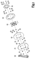
- Fig. 1 shows a crank set according to the invention, wherein at least the freewheel device 29 is part of this crank set.
- the freewheel device 29 has an inner hole ring with four (preferably 3-5) holes and a pitch circle diameter L1 of 58 mm or 64 mm.
- L1 pitch circle diameter
- L2 104 mm
- the motor chain 5 is mounted with an intermediate chain guide disc 59 on the freewheel device 29.
- the pedal crank 30 is screwed into the freewheel device 29 via an external thread of the pedal crank 30 and an internal thread of the freewheel device 29.
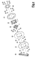
- Fig. 2 shows a further inventive crank set, in which the freewheel device 25, 26 consists of a freewheel 26 and a chainring adapter 25.
- the chainring adapter 25 has an outer ring of holes with pitch circle diameter L2, to which larger chainrings can be fastened.
- freewheel 26 and chainring adapter 25 are made of different materials.
- the chainring adapter 25 is made of aluminum, while necessarily made of more robust material manufactured freewheel 26 is made of stainless steel. The necessary amount of heavy and expensive stainless steel is therefore reduced which leads to a weight and réelleotpimtechnik.
- a reduction of the unavoidable crop in the production of the individual parts is achieved.
- the chainring adapter 25 has four holes for mounting the freewheel 26 on the chainring adapter 25. Furthermore, there are four further laterally offset holes of a bolt circle diameter L1 for mounting small chainrings 28 on the chainring adapter 25.
- the freewheel device consists of a chainring adapter and a freewheel. In this way, weight and cost can be optimized, since the adapter and the freewheel are made of the most suitable in terms of cost, weight and stability material.
Landscapes
- Engineering & Computer Science (AREA)
- Chemical & Material Sciences (AREA)
- Combustion & Propulsion (AREA)
- Mechanical Engineering (AREA)
- Transportation (AREA)
- General Engineering & Computer Science (AREA)
- Battery Mounting, Suspending (AREA)
- Devices For Conveying Motion By Means Of Endless Flexible Members (AREA)
- Gears, Cams (AREA)
- Transmission Devices (AREA)
- Motorcycle And Bicycle Frame (AREA)
Description
Die Erfindung betrifft ein Kurbelset, das für ein motorisiertes Fahrrad, insbesondere ein elektrisch motorisiertes Fahrrad verwendbar ist.The invention relates to a crank set, which is suitable for a motorized bicycle, in particular an electrically motorized bicycle.
Die
Die
Aufgabe der vorliegenden Erfindung ist es, die Nachteile des Stands der Technik zu verbessern.The object of the present invention is to improve the disadvantages of the prior art.
Die Aufgabe wird durch die unabhängigen Ansprüche gelöst. Vorteilhafte Weiterbildungen sind in den Unteransprüchen definiert.The object is solved by the independent claims. Advantageous developments are defined in the subclaims.
Insbesondere wird die Aufgabe gelöst durch ein Kurbelset für ein Fahrrad, wobei das Kurbelset eine Freilaufeinrichtung (25, 26, 29) mit Löchern zur Befestigung von Kettenblättern (5, 27, 28) aufweist, wobei die Löcher gemäß mindestens zweier verschiedener Lochkreise mit Durchmessern L1 und L2 ringförmig angeordnet sind und eines der montierbaren Kettenblätter (5, 27, 28) ein Motorkettenblatt (5) ist und das Kurbelset eine Kettenführungsscheibe (59) aufweist, die zwischen das Motorkettenblatt (5) und die übrigen Kettenblätter (27, 28) montierbar ist.In particular, the object is achieved by a crank set for a bicycle, wherein the crank set has a freewheel device (25, 26, 29) with holes for attachment of chainrings (5, 27, 28), wherein the holes according to at least two different bolt circles with diameters L1 and L2 are arranged annularly and one of the mountable chainrings (5, 27, 28) is a motor chainring (5) and the crank set comprises a chain guide disc (59) mountable between the motor chainring (5) and the remaining chainrings (27, 28) is.
Die Kettenführungsscheibe weist bevorzugt einen größeren Durchmesser als die vorhandenen Kettenblätter auf. Durch diese Scheibe wird verhindert, dass die Antriebskette zum Hinterrad auf das Motorkettenblatt läuft und dass die Antriebskette zum Motor auf ein Kettenblatt für die Antriebskette zum Hinterrad läuft. Es wird ein Abspringen der beiden Ketten bzw. Zahnriemen verhindert.The chain guide disk preferably has a larger diameter than the existing chainrings. This disc prevents the drive chain to the rear wheel from running on the engine chainring and that the drive chain to the engine runs on a chainring for the drive chain to the rear wheel. It is prevented jumping off the two chains or timing belt.
Das Motorkettenblatt ist bevorzugt zur Führung einer Kette zu einem Elektromotor eingerichtet, während andere Kettenblätter zur Führung einer Kette zum Hinterrad eingerichtet sind.The engine chainring is preferably arranged to guide a chain to an electric motor, while other chainrings are set up to guide a chain to the rear wheel.
Durch die erfindungsgemäße Freilaufeinrichtung sind verschiedene Kettenblätter montierbar und über einen Freilauf von der Tretkurbel getrennt. Somit können verschieden große Kettenblätter einfach montiert werden oder z.B. die vorhandenen Kettenblätter des Fahrrads mitsamt der vorhandenen Gangschaltung verwendet werden, wenn dieses mit einem Elektroantrieb nachgerüstet wird, so dass eines dieser Kettenblätter über eine extra Kette durch einen Motor angetrieben wird. Die gebräuchlichen Kettenblätter weisen üblicherweise verschiedene Lochkreise auf, so dass mit der erfindungsgemäßen Freilaufeinrichtung eine Kompatibilität zu auf dem Markt vorhandenen Kettenblättern erreichbar ist während im Stand der Technik speziell angefertigte Kettenblätter notwendig sind. Die Freilaufeinrichtung ist damit flexibel für verschiedene Kettenblätter einsetzbar. Die Freilaufeinrichtung erlaubt die Drehung zweier gegeinander verdrehbarer Komponenten des Freilaufs nur in einer Drehrichtung. An einer verdrehbaren Komponente ist eine Kurbel anbringbar und an der anderen verdrehbaren Komponente mindestens ein Kettenblatt, bevorzugt bis zu drei Kettenblätter. Durch die Freilaufeinrichtung wird ein Betriebsmodus unterstützt, in dem ohne Pedalieren nur mit Motorantrieb gefahren wird.The freewheel device according to the invention various chainrings are mounted and separated by a freewheel from the crank. Thus, different sized chainrings can be easily mounted or eg the existing chainrings of the bicycle can be used together with the existing gear, if this is retrofitted with an electric drive, so that one of these chainrings is driven by an extra chain by a motor. The conventional chainrings usually have different bolt circles, so that with the freewheel device according to the invention a compatibility with existing on the market chainrings can be achieved while in the art specially made chainrings are necessary. The freewheel device is thus flexible for different chainrings used. The freewheel device allows the rotation of two gegeinander rotatable components of the freewheel only in one direction. A crank is attachable to a rotatable component and at least one chainring, preferably up to three chainrings, to the other rotatable component. The freewheel device supports an operating mode in which pedaling is only performed with motor drive.
Je Lochkreis sind bevorzugt mindestens drei bevorzugt vier, fünf oder mehr Löcher in der Freilaufeinrichtung eingebracht. Bevorzugt weisen die Löcher, bevorzugt die des Lochkreises mit Durchmesser L1, ein Innengewinde auf, wodurch kleine Kettenblätter ohne Gewindehülsen direkt anschraubbar sind.Per hole circle preferably at least three, preferably four, five or more holes are introduced in the freewheel device. Preferably, the holes, preferably those of the bolt circle having a diameter L1, an internal thread, whereby small chainrings without threaded sleeves are screwed directly.
In einem weiteren Ausführungsbeispiel der vorliegenden Erfindung sind L1 und L2 gleich Durchmessern der Lochkreise der montierbaren Kettenblätter (5, 27, 28).In another embodiment of the present invention, L1 and L2 are equal to diameters of the pitch circles of the mountable chainrings (5, 27, 28).
L1 ist bevorzugt der Durchmesser des Lochkreises für ein kleines Ketteblatt mit bevorzugt 20 bis 24, besonders bevorzugt 22 Zähnen. L1 liegt bevorzugt im Bereich von 50 mm bis 80 mm und beträgt bevorzugt 58 mm, besonders bevorzugt 64 mm.L1 is preferably the diameter of the circle of holes for a small chain blade with preferably 20 to 24, particularly preferably 22 teeth. L1 is preferably in the range of 50 mm to 80 mm and is preferably 58 mm, particularly preferably 64 mm.
L2 ist bevorzugt der Durchmesser des Lochkreises eines Kettenblatts mittlerer Größe, mit 30 bis 38 Zähnen, bis großer Größe, mit mehr als 38 Zähnen am Kettenblatt. L2 liegt bevorzugt im Bereich von 90 mm bis 146 mm, besonders bevorzugt 100 mm bis 120 mm, und beträgt besonders bevorzugt 104 mm.L2 is preferably the diameter of the pitch circle of a medium sized chainring, with 30 to 38 teeth, to large size, with more than 38 teeth on the chainring. L2 is preferably in the range of 90 mm to 146 mm, particularly preferably 100 mm to 120 mm, and is particularly preferably 104 mm.
Bevorzugt weisen die Lochkreise mit Durchmessern L1 und L2 dieselben Anzahlen von Löchern auf wie Lochkreise der montierbaren Kettenblätter.The hole circles with diameters L1 and L2 preferably have the same number of holes as hole circles of the mountable chainrings.
In einem weiteren Ausführungsbeispiel der vorliegenden Erfindung weist die Freilaufeinrichtung (25, 26) einen Kettenblattadapter (25) und einen Freilauf (26) auf, die miteinander durch Schrauben (35) verschraubbar sind.In a further embodiment of the present invention, the freewheel device (25, 26) has a sprocket adapter (25) and a freewheel (26), which are screwed together by screws (35).
Der Kettenblattadapter ist bevorzugt eine ringförmige Scheibe, bevorzugt mit einer inneren Eintiefung, mit einem ersten Ring von mindestens drei bevorzugt vier, fünf oder mehr Löchern, die für die Montage des Freilaufs und bevorzugt eines kleinen Kettenblatts bestimmt sind und bevorzugt gemäß dem Lochkreisdurchmesser L1 angeordnet sind, und einen zweiten Ring von mindestens drei, bevorzugt vier oder mehr Löchern, die für die Montage von Kettenritzeln bestimmt sind und bevorzugt gemäß dem Lochkreisdurchmesser L2 angeordnet sind. Bevorzugt sind die Löcher des zweiten Rings in Ausbuchtungen des Kettenblattadapters angeordnet. An dem Kettenblattadapter sind bevorzugt Kettenblätter mit 104 mm Lochkreis (z. B. 32-46 Zähne) wie auch Kettenblätter mit 20 bis 24, z. B. 22 Zähnen, und kleinen Lochkreis (58 mm, 64 mm) befestigbar.The chainring adapter is preferably an annular disc, preferably with an inner recess, with a first ring of at least three preferably four, five or more holes, which are intended for the assembly of the freewheel and preferably a small chainring and preferably according to are arranged in the pitch circle diameter L1, and a second ring of at least three, preferably four or more holes, which are intended for the mounting of chain sprockets and are preferably arranged according to the pitch circle diameter L2. Preferably, the holes of the second ring are arranged in recesses of the sprocket adapter. On the chainring adapter are preferably chainrings with 104 mm bolt circle (eg 32-46 teeth) as well as chainrings with 20 to 24, z. B. 22 teeth, and small hole circle (58 mm, 64 mm) fastened.
Der Freilauf weist bevorzugt einen Ring mit drei, bevorzugt vier oder mehr, Löchern für die Montage des Kettenblattadapters auf, wobei die Löcher bevorzugt gemäß einem Lochkreisdurchmesser L3 angeordnet sind. Wenn L1 und L3 unterschiedlich sind, weist der Kettenblattadapter zusätzliche Löcher in einer Anordnung gemäß Lochkreisdurchmesser L3 für die Fixierung des Freilaufs am Kettenblattadapter sowie einen Lochkreis mit Durchmesser L1 für ein kleines Kettenblatt auf.The freewheel preferably has a ring with three, preferably four or more, holes for mounting the sprocket adapter, wherein the holes are preferably arranged according to a pitch circle diameter L3. When L1 and L3 are different, the sprocket adapter has additional holes in a pitch circle diameter L3 arrangement for fixing the freewheel on the sprocket adapter, and a small diameter bolt hole circle L1.
Durch den Kettenblattadapter ist auch eine kostengünstige Produktion möglich. Der Freilauf ist wegen der hohen Kräfte bevorzugt aus Edelstahl, das gegenüber Aluminium in der Verarbeitung teuer und schwer ist. Durch den Adapter können der Adapter selbst und auch die Kettenblätter aus günstigeren und auch leichteren Materialien wie z. B. Alu vorgesehen werden. Eine Herstellung eines Freilaufs mit integral angebrachtem Kettenblattadapter bedarf eines höheren Materialaufwand von teurem Material, der insbesondere durch den anfallenden Verschnitt noch weiter erhöht wird. Daher führt diese Lösung zu hoher Flexibilität, geringem Gewicht und kostengünstiger Produktion.The chainring adapter also enables cost-effective production. The freewheel is preferably made of stainless steel because of the high forces, which is expensive and heavy compared to aluminum in the processing. Through the adapter, the adapter itself and the chainrings from cheaper and lighter materials such. B. Alu be provided. A production of a freewheel with integrally attached sprocket adapter requires a higher material cost of expensive material, which is further increased in particular by the resulting waste. Therefore, this solution leads to high flexibility, low weight and low cost production.
In einem weiteren Ausführungsbeispiel der vorliegenden Erfindung weist der Freilauf (26) Löcher auf, die gemäß mindestens einem Lochkreis mit Durchmesser L3 ringförmig angeordnet sind, wobei L3 der gleiche Durchmesser ist wie einer der Durchmesser L1 und L2.In a further embodiment of the present invention, the freewheel (26) has holes which are annular in accordance with at least one diameter circle L3 are arranged, wherein L3 is the same diameter as one of the diameters L1 and L2.
Auf diese Weise ist durch dieselben Schrauben sowohl der Freilauf an den Kettenblattadapter als auch mindestens ein Kettenblatt mit dem Lochkreisdurchmesser L3 an den Kettenblattadapter anschraubbar, bei der Montage Schrauben eingespart werden können.In this way, by the same screws both the freewheel on the chainring adapter and at least one chainring with the pitch circle diameter L3 screwed to the sprocket adapter, screws can be saved in the assembly.
In einem weiteren Ausführungsbeispiel der vorliegenden Erfindung weist die Freilaufeinrichtung (25, 26, 29) eine axiale Öffnung mit einem Innengewinde auf, wobei in die Öffnung eine Tretkurbel (30), welche ein axiales Außengewinde aufweist, einschraubbar ist. Auf diese Weise ist eine schnelle Montage der Kurbel an dem Freilauf durchführbar.In a further embodiment of the present invention, the freewheel device (25, 26, 29) has an axial opening with an internal thread, wherein in the opening a pedal crank (30), which has an axial external thread, can be screwed. In this way, a quick installation of the crank on the freewheel is feasible.
Die Erfindung soll nun anhand von Zeichnungen beispielhaft weiter veranschaulicht werden. Hierbei zeigen:
- Figur 1
- ein erfindungsgemäßes Kurbelset, wobei mindestens die
Freilaufeinrichtung 29 Bestandteil dieses Kurbelsets ist, - Figur 2
- ein weiteres erfindungsgemäßes Kurbelset, bei dem die
Freilaufeinrichtung 25, 26 aus einem Freilauf 26 und einemKettenblattadapter 25 besteht.
- FIG. 1
- an inventive crank set, wherein at least the
freewheel device 29 is part of this crank set, - FIG. 2
- Another inventive crank set, in which the
freewheel device 25, 26 consists of a freewheel 26 and achainring adapter 25.
Aufgrund dieser Freilaufeinrichtung 29 sind vorhandene Kettenblätter nutzbar und um das Motorkettenblatt 5 erweiterbar, wobei auch ein Kettenführungsblatt 59 dazwischenschaltbar ist. Durch die Freilaufeinrichtung 29 sind die verschiedenen Betriebsmodi des Elektrofahrrads möglich. Die bisherigen Gänge des Fahrrads sind damit weiterhin wie gewohnt nutzbar.Due to this
Durch die Verwendung des Kettenblattadapters 25 mit anschraubbarem Freilauf 26 anstatt einer integralen Freilaufeinrichtung 29 sind Freilauf 26 und Kettenblattadapter 25 aus verschiedenen Materialien fertigbar. Der Kettenblattadapter 25 besteht aus Aluminium, während der notwendigerweise aus robusterem Material zu fertigende Freilauf 26 aus Edelstahl gefertigt ist. Die notwendige Menge des schweren und teuren Edelstahl wird daher reduziert was zu einer Gewichts- und Kostenotpimierung führt. Zudem wird durch die Aufteilung der Freilaufeinrichtung in Freilauf 26 und Kettenblattadapter 25 eine Reduktion des nicht vermeidbaren Verschnitts bei der Fertigung der Einzelteile erreicht.By using the
In einem anderen Ausführungsbeispiel ähnlich dem in
Mit dieser Erfindung ist eine Möglichkeit bereitgestellt worden, Kettenblätter verschiedener Lochkreisgrößen, wie sie in der Fahrradindustrie üblich sind, in einfacher Weise mittels Schrauben an eine Freilaufeinrichtung zu schrauben. Auf diese Weise können die vorhandenen Kettenblätter eines Fahrrads verwendet werden. Während große Kettenblätter zum Beispiel an die Löcher, die mit Lochkreisdurchmesser L2 angeordnet sind, anschraubbar sind, sind kleinere Kettenblätter mit kleinerem Lochkreis an die Löcher, die mit Lochkreisdurchmesser L1 angeordnet sind, anschraubbar. In einer bevorzugten Variante besteht die Freilaufeinrichtung aus einem Kettenblattadapter und einem Freilauf. Auf diese Weise sind Gewicht und Kosten optimierbar, da der Adapter und der Freilauf aus dem je hinsichtlich Kosten, Gewicht und Stabilität geeignetsten Material fertigbar sind.With this invention has been provided a way chain screws of different bolt circle sizes, as are common in the bicycle industry, to screw easily by means of screws to a freewheel device. In this way, the existing chainrings of a bicycle can be used. For example, while large chainrings can be screwed to the holes arranged with pitch circle diameter L2, smaller chainrings with a smaller pitch circle can be screwed to the holes arranged with pitch circle diameter L1. In a preferred variant, the freewheel device consists of a chainring adapter and a freewheel. In this way, weight and cost can be optimized, since the adapter and the freewheel are made of the most suitable in terms of cost, weight and stability material.
- 55
- MotorkettenblattMotor chainring
- 2525
- KettenblattadapterChainring Adapter
- 2626
- Freilauffreewheel
- 2727
- Kettenblattchainring
- 2828
- Kettenblattchainring
- 2929
- Freilauf mit integriertem KettenblattadapterFreewheel with integrated chainring adapter
- 3030
- Tretkurbelcrank
- 3131
- Schraubescrew
- 3232
- Schraubescrew
- 3333
- Gewindehülsethreaded sleeve
- 3434
- Distanzringspacer
- 3535
- Schraubescrew
- 5959
- KettenführungsscheibeChain guide plate
Claims (5)
- A crank set for a bicycle, wherein the crank set comprises a freewheel device (25, 26, 29) with holes for the attachment of chain rings (5, 27, 28), wherein the holes are arranged in a ring-shaped manner according to at least two different hole circles with diameters L1 and L2, characterised in that one of the mountable chain rings (5, 27, 28) is a motor chain ring (5), and the crank set comprises a chain guide disc (59) that is mountable between the motor chain ring (5) and the retaining chain rings (27, 28).
- The crank set according to claim 1,
wherein L1 and L2 are equal to diameters of the hole circles of the countable chain rings (5, 27, 28). - The crank set according to one of the preceding claims
wherein the freewheel device (25, 26) comprises a chain ring adapter (25) and a freewheel (26) that can be connected to each other by means of screws (35). - The crank set according to claim 3,
wherein the freewheel (26) comprises holes that are arranged in a ring-shaped manner according to at least one hole circle with diameter L3, wherein L3 is the same diameter as one of the diameters L1 and L2. - The crank set according to any one of the preceding claims,
wherein the freewheel device (25, 26, 29) comprises an axial aperture with an internal thread, and wherein a pedal crank (30) that comprises an axial external thread can be screwed into the aperture.
Applications Claiming Priority (2)
| Application Number | Priority Date | Filing Date | Title |
|---|---|---|---|
| AT0053810U AT12217U1 (en) | 2010-08-31 | 2010-08-31 | ADAPTER FOR CONNECTING AN ELECTRIC DRIVE UNIT TO VEHICLE FRAME |
| PCT/EP2011/003637 WO2012028226A1 (en) | 2010-08-31 | 2011-07-20 | Crankset for a motorized cycle |
Publications (2)
| Publication Number | Publication Date |
|---|---|
| EP2611684A1 EP2611684A1 (en) | 2013-07-10 |
| EP2611684B1 true EP2611684B1 (en) | 2015-07-15 |
Family
ID=44898381
Family Applications (2)
| Application Number | Title | Priority Date | Filing Date |
|---|---|---|---|
| EP11737900.8A Not-in-force EP2611682B1 (en) | 2010-08-31 | 2011-07-20 | Mounting adapter for an electric cycle |
| EP11735801.0A Active EP2611684B1 (en) | 2010-08-31 | 2011-07-20 | Crankset for a motorized cycle |
Family Applications Before (1)
| Application Number | Title | Priority Date | Filing Date |
|---|---|---|---|
| EP11737900.8A Not-in-force EP2611682B1 (en) | 2010-08-31 | 2011-07-20 | Mounting adapter for an electric cycle |
Country Status (6)
| Country | Link |
|---|---|
| US (2) | US9194446B2 (en) |
| EP (2) | EP2611682B1 (en) |
| AT (1) | AT12217U1 (en) |
| CA (2) | CA2809064C (en) |
| ES (2) | ES2549589T3 (en) |
| WO (2) | WO2012028227A1 (en) |
Families Citing this family (23)
| Publication number | Priority date | Publication date | Assignee | Title |
|---|---|---|---|---|
| EP2666707A1 (en) | 2012-05-25 | 2013-11-27 | Klaus Kraft | Electric drive for a bicycle |
| FR3007384A1 (en) * | 2013-06-19 | 2014-12-26 | Cycloboost | MEDIUM ELECTRIC MOTOR SUPPORT DEVICE FOR TRANSFORMING A CLASSIC ELECTRIC VELO BIKE WITH ELECTRIC POWER SUPPORT WITH A PEDAL ENGINE |
| AT13508U1 (en) * | 2013-08-02 | 2014-02-15 | Mario Preining | Mounting system for connecting an electric drive system to bicycles |
| WO2015039132A1 (en) * | 2013-09-16 | 2015-03-19 | Decordova Daniel | Multi-modal vehicles capable of legally traveling in different classification categories |
| AT14293U1 (en) * | 2014-01-13 | 2015-07-15 | Kraut Daniel | Set with electric motor for bicycles |
| DE102014100367B4 (en) * | 2014-01-14 | 2023-03-02 | Miranda & Irmão, Lda. | System clamping nut with chain guard |
| US9359040B2 (en) | 2014-06-20 | 2016-06-07 | Securience, LLC | Electric bike retrofit for disc brakes bicycle |
| DE202014103987U1 (en) | 2014-08-26 | 2014-09-22 | Ego Sports Gmbh | Mounting system for fixing an electric motor |
| AT14642U1 (en) * | 2015-04-24 | 2016-03-15 | Daniel Preining | Mounting system for a drive unit on a sprung bicycle frame |
| WO2016206731A1 (en) * | 2015-06-24 | 2016-12-29 | André Armando Muff | Bicycle frame comprising a receiving device for a drive housing |
| JP6514995B2 (en) * | 2015-08-31 | 2019-05-15 | 株式会社シマノ | Bicycle guard and drive unit having the same |
| FR3043982A1 (en) * | 2015-11-25 | 2017-05-26 | Matthieu Faury | MOTORIZED OR MOTORIZED, REMOVABLE AND MULTI-POSITIVE MOTORIZATION SYSTEM FOR TRANSFORMING A CLASSIC PEDAL VEHICLE IN MOTORIZED AND / OR ASSISTED PEDAL VEHICLES |
| WO2017131655A1 (en) * | 2016-01-27 | 2017-08-03 | Ford Global Technologies, Llc | Foldable bicycle and storage system |
| WO2017131656A1 (en) | 2016-01-27 | 2017-08-03 | Ford Global Technologies, Llc | Foldable bicycle and storage system |
| US10527130B2 (en) * | 2016-09-30 | 2020-01-07 | Grant Shirley | Gear lift box assembly |
| CN107521608B (en) * | 2017-08-29 | 2023-03-31 | 黄大成 | Bicycle booster based on wireless handle control and bicycle equipped with booster |
| KR102013822B1 (en) * | 2017-12-28 | 2019-10-21 | 주식회사 명지 | A method for mounting a motor bracket and a mortor bracket for electric bicycle |
| DE102018000639A1 (en) * | 2018-01-26 | 2019-08-01 | Biketec Ag | BICYCLE FRAME, ELECTRIC BIKE AND ADAPTER SET |
| DE102018219898A1 (en) * | 2018-11-21 | 2020-05-28 | Robert Bosch Gmbh | Drive arrangement of an electrically operated bicycle |
| WO2022183252A1 (en) * | 2021-03-05 | 2022-09-09 | Williams Racing Products Pty Ltd | Front freewheel arrangement for bicycle |
| JP2023092285A (en) * | 2021-12-21 | 2023-07-03 | ヤマハ発動機株式会社 | vehicle |
| US12522318B2 (en) * | 2021-12-31 | 2026-01-13 | Zwift, Inc. | Single-sprocket system for a bicycle trainer |
| US20230312052A1 (en) * | 2022-03-18 | 2023-10-05 | Bikefin Ebike Inc. | Electric bicycle conversion kits |
Family Cites Families (30)
| Publication number | Priority date | Publication date | Assignee | Title |
|---|---|---|---|---|
| DE892561C (en) * | 1950-12-13 | 1953-10-08 | Georges Navet | Fastening device for sprockets on the treadmills of bicycles |
| US4144773A (en) * | 1976-07-12 | 1979-03-20 | Addicks Lyle F | Bicycle sprocket wheel |
| DE3117415A1 (en) * | 1981-05-02 | 1982-11-18 | Wolfgang Dr.-Ing. 8740 Bad Neustadt Volkrodt | Vehicle with two or more wheels and with chainless drive |
| US4871042A (en) | 1988-09-01 | 1989-10-03 | Hsu Chi Chu | Electric bicycle |
| GB2249529A (en) | 1990-10-30 | 1992-05-13 | Hsu Chi Hsueh | Electric motor-assisted pedal bicycle with battery and solar power source |
| US5213550A (en) * | 1992-01-23 | 1993-05-25 | Wu Chuen Fwu | Variable speed-type bicycle chain ring assembly |
| US5242028A (en) | 1992-01-24 | 1993-09-07 | Murphy Lisa J | Motorized bicycle drive system |
| US5314366A (en) * | 1993-03-25 | 1994-05-24 | Palm Kirby A | Adapter chainring |
| US5426997A (en) * | 1993-06-28 | 1995-06-27 | Brion; Donald G. | Bicycle chain drive assembly |
| USD356526S (en) * | 1993-10-18 | 1995-03-21 | Greg Burns | Bicycle crank set |
| JPH08290795A (en) | 1995-02-21 | 1996-11-05 | Seiko Epson Corp | Auxiliary power unit |
| JPH0911970A (en) * | 1995-04-28 | 1997-01-14 | Tec Corp | Bicycle with auxiliary power device |
| EP0755854A1 (en) | 1995-07-25 | 1997-01-29 | Merida Industry Co., Ltd. | Electrical drive for a bicycle |
| US5766106A (en) * | 1995-09-08 | 1998-06-16 | Edwards; Craig H. | Crankset assembly |
| JP3327079B2 (en) | 1995-11-29 | 2002-09-24 | 松下電器産業株式会社 | Electric bicycle |
| JP3578541B2 (en) * | 1996-02-20 | 2004-10-20 | 株式会社エクセディ | Viscous damper mechanism |
| US5934401A (en) * | 1997-02-20 | 1999-08-10 | Currie Technologies, Incorporated | Precision direct drive mechanism for a power assist apparatus for a bicycle |
| JP4189936B2 (en) * | 1999-05-25 | 2008-12-03 | 本田技研工業株式会社 | Electric assist bicycle |
| US6352131B1 (en) * | 2000-01-25 | 2002-03-05 | Jung-Te Lin | Bicycle's power train |
| US6412800B1 (en) * | 2001-03-05 | 2002-07-02 | Fabrizio Tommei | Universal kit for the application of an electric motor on a standard bicycle transforming same bicycle into a bicycle with pedal assist from the electric motor |
| JP2003194194A (en) * | 2001-12-28 | 2003-07-09 | Sunstar Eng Inc | Gear box and motor-assisted bicycle using the same |
| US20060094550A1 (en) * | 2004-11-01 | 2006-05-04 | Shimano Inc. | Bicycle crankset |
| GB2440132A (en) * | 2006-07-20 | 2008-01-23 | Andrew Mediwake | Bicycle transmission drivable by pedal or assist motor |
| US20080032835A1 (en) * | 2006-08-04 | 2008-02-07 | Reynolds Mark A | Multiple Sprocket Chain Guide For Front Bicycle Derailleur |
| CA2562222A1 (en) | 2006-09-26 | 2008-03-26 | Peter Johann Kielland | Dual-posture electric assist bicycle having both upright and recumbent seating modes |
| FR2912988B1 (en) * | 2007-02-23 | 2009-04-17 | Look Cycle Internat Sa | "CYCLE PEDALER WITH DOUBLE TRAYS" |
| FR2921630B1 (en) * | 2007-10-01 | 2010-04-02 | Koxx Sarl | PEDALIER MULTI TRAY WITH INTEGRATED FREE WHEEL |
| US7871347B2 (en) * | 2007-10-11 | 2011-01-18 | Shimano Inc. | Bicycle rear sprocket assembly |
| DE102008007710A1 (en) * | 2008-02-04 | 2009-08-06 | Clean Mobile Ag | Chain drive for transforming motor torque of electric motor in bicycle, has set of gear rims that is arranged on shaft i.e. pedal crankshaft, and transmission chain i.e. motor chain, provided in each of stages for transmission of torque |
| US8256554B2 (en) * | 2010-01-22 | 2012-09-04 | Foster Assets Corporation | Pedal driven apparatus having a motor |
-
2010
- 2010-08-31 AT AT0053810U patent/AT12217U1/en not_active IP Right Cessation
-
2011
- 2011-07-20 ES ES11735801.0T patent/ES2549589T3/en active Active
- 2011-07-20 US US13/818,715 patent/US9194446B2/en not_active Expired - Fee Related
- 2011-07-20 CA CA2809064A patent/CA2809064C/en active Active
- 2011-07-20 CA CA2809067A patent/CA2809067C/en not_active Expired - Fee Related
- 2011-07-20 WO PCT/EP2011/003649 patent/WO2012028227A1/en not_active Ceased
- 2011-07-20 ES ES11737900.8T patent/ES2630009T3/en active Active
- 2011-07-20 WO PCT/EP2011/003637 patent/WO2012028226A1/en not_active Ceased
- 2011-07-20 EP EP11737900.8A patent/EP2611682B1/en not_active Not-in-force
- 2011-07-20 EP EP11735801.0A patent/EP2611684B1/en active Active
- 2011-07-20 US US13/818,701 patent/US20130153321A1/en not_active Abandoned
Also Published As
| Publication number | Publication date |
|---|---|
| ES2549589T3 (en) | 2015-10-29 |
| US20130150194A1 (en) | 2013-06-13 |
| EP2611682B1 (en) | 2017-03-08 |
| US20130153321A1 (en) | 2013-06-20 |
| AT12217U1 (en) | 2012-01-15 |
| WO2012028226A1 (en) | 2012-03-08 |
| EP2611682A1 (en) | 2013-07-10 |
| CA2809064C (en) | 2017-01-17 |
| CA2809064A1 (en) | 2012-03-08 |
| CA2809067A1 (en) | 2012-03-08 |
| ES2630009T3 (en) | 2017-08-17 |
| WO2012028227A1 (en) | 2012-03-08 |
| US9194446B2 (en) | 2015-11-24 |
| CA2809067C (en) | 2015-09-15 |
| EP2611684A1 (en) | 2013-07-10 |
Similar Documents
| Publication | Publication Date | Title |
|---|---|---|
| WO2012028226A1 (en) | Crankset for a motorized cycle | |
| DE10260565B4 (en) | The sprocket assembly | |
| DE102007006852B4 (en) | Bicycle sprocket assembly | |
| EP3630592B1 (en) | Bicycle having electric drive with power distribution | |
| DE102017008222A1 (en) | Bicycle front sprocket assembly | |
| DE102015000474A1 (en) | BICYCLE CHAINRING | |
| DE102009017014A1 (en) | Transmission, in particular planetary gear with a flange and a ring gear | |
| DE102015100785A1 (en) | TRAVEL HUB | |
| EP2380806B1 (en) | Power transmission unit | |
| AT13508U1 (en) | Mounting system for connecting an electric drive system to bicycles | |
| DE102013104370B4 (en) | Bicycle power unit and electrically assisted bicycle | |
| EP2731857A1 (en) | Rear wheel drive | |
| DE202016100725U1 (en) | Bicycle hub assembly | |
| DE3842113A1 (en) | CLOSED, 1-AXLE DRIVE MECHANISM FOR BICYCLES | |
| EP3936424A1 (en) | Auxiliary electric drive for a bicycle | |
| DE102012022352A1 (en) | Vehicle, particularly bicycle, has wheel, where internal gear is arranged on wheel, and internal gear is provided in engagement with gear wheel, which is driven by electric motor | |
| DE102015203677B3 (en) | Wheel hub motor for a bicycle as well as bicycle with the wheel hub motor | |
| DE102023115800B3 (en) | DRIVE SYSTEM WITH ONE DRIVE SHAFT AND ONE CHAINRING | |
| DE212019000409U1 (en) | Drive system for an e-bike | |
| DE102021110725B4 (en) | Driving device for an electric bicycle and electric bicycle | |
| DE102013214701A1 (en) | pedal crankshaft | |
| DE102022129554A1 (en) | Hub especially for bicycles | |
| DE202013105775U1 (en) | Dual drive hub assembly | |
| DE102010015355A1 (en) | Compression joint for bicycle, has crankshaft attached to base body, and clamping ring inserted into ring holder in base body, where non-cylindrical inner profile of apertures is arranged in base body and/or clamping ring | |
| DE102013200887A1 (en) | Gear for a gear or a bicycle |
Legal Events
| Date | Code | Title | Description |
|---|---|---|---|
| PUAI | Public reference made under article 153(3) epc to a published international application that has entered the european phase |
Free format text: ORIGINAL CODE: 0009012 |
|
| 17P | Request for examination filed |
Effective date: 20130402 |
|
| AK | Designated contracting states |
Kind code of ref document: A1 Designated state(s): AL AT BE BG CH CY CZ DE DK EE ES FI FR GB GR HR HU IE IS IT LI LT LU LV MC MK MT NL NO PL PT RO RS SE SI SK SM TR |
|
| DAX | Request for extension of the european patent (deleted) | ||
| GRAP | Despatch of communication of intention to grant a patent |
Free format text: ORIGINAL CODE: EPIDOSNIGR1 |
|
| INTG | Intention to grant announced |
Effective date: 20150211 |
|
| RAP1 | Party data changed (applicant data changed or rights of an application transferred) |
Owner name: EGO SPORTS GMBH |
|
| RIN1 | Information on inventor provided before grant (corrected) |
Inventor name: EITSCHBERGER, MATTHIAS Inventor name: PREINING, DANIEL |
|
| GRAS | Grant fee paid |
Free format text: ORIGINAL CODE: EPIDOSNIGR3 |
|
| GRAA | (expected) grant |
Free format text: ORIGINAL CODE: 0009210 |
|
| AK | Designated contracting states |
Kind code of ref document: B1 Designated state(s): AL AT BE BG CH CY CZ DE DK EE ES FI FR GB GR HR HU IE IS IT LI LT LU LV MC MK MT NL NO PL PT RO RS SE SI SK SM TR |
|
| REG | Reference to a national code |
Ref country code: CH Ref legal event code: EP Ref country code: GB Ref legal event code: FG4D Free format text: NOT ENGLISH |
|
| REG | Reference to a national code |
Ref country code: IE Ref legal event code: FG4D Free format text: LANGUAGE OF EP DOCUMENT: GERMAN |
|
| REG | Reference to a national code |
Ref country code: AT Ref legal event code: REF Ref document number: 736631 Country of ref document: AT Kind code of ref document: T Effective date: 20150815 |
|
| REG | Reference to a national code |
Ref country code: DE Ref legal event code: R096 Ref document number: 502011007339 Country of ref document: DE |
|
| REG | Reference to a national code |
Ref country code: ES Ref legal event code: FG2A Ref document number: 2549589 Country of ref document: ES Kind code of ref document: T3 Effective date: 20151029 |
|
| REG | Reference to a national code |
Ref country code: CH Ref legal event code: NV Representative=s name: SCHMAUDER AND PARTNER AG PATENT- UND MARKENANW, CH |
|
| REG | Reference to a national code |
Ref country code: FR Ref legal event code: PLFP Year of fee payment: 5 |
|
| REG | Reference to a national code |
Ref country code: LT Ref legal event code: MG4D |
|
| REG | Reference to a national code |
Ref country code: NL Ref legal event code: FP |
|
| PG25 | Lapsed in a contracting state [announced via postgrant information from national office to epo] |
Ref country code: FI Free format text: LAPSE BECAUSE OF FAILURE TO SUBMIT A TRANSLATION OF THE DESCRIPTION OR TO PAY THE FEE WITHIN THE PRESCRIBED TIME-LIMIT Effective date: 20150715 Ref country code: LV Free format text: LAPSE BECAUSE OF FAILURE TO SUBMIT A TRANSLATION OF THE DESCRIPTION OR TO PAY THE FEE WITHIN THE PRESCRIBED TIME-LIMIT Effective date: 20150715 Ref country code: NO Free format text: LAPSE BECAUSE OF FAILURE TO SUBMIT A TRANSLATION OF THE DESCRIPTION OR TO PAY THE FEE WITHIN THE PRESCRIBED TIME-LIMIT Effective date: 20151015 Ref country code: GR Free format text: LAPSE BECAUSE OF FAILURE TO SUBMIT A TRANSLATION OF THE DESCRIPTION OR TO PAY THE FEE WITHIN THE PRESCRIBED TIME-LIMIT Effective date: 20151016 Ref country code: LT Free format text: LAPSE BECAUSE OF FAILURE TO SUBMIT A TRANSLATION OF THE DESCRIPTION OR TO PAY THE FEE WITHIN THE PRESCRIBED TIME-LIMIT Effective date: 20150715 |
|
| PG25 | Lapsed in a contracting state [announced via postgrant information from national office to epo] |
Ref country code: HR Free format text: LAPSE BECAUSE OF FAILURE TO SUBMIT A TRANSLATION OF THE DESCRIPTION OR TO PAY THE FEE WITHIN THE PRESCRIBED TIME-LIMIT Effective date: 20150715 Ref country code: SE Free format text: LAPSE BECAUSE OF FAILURE TO SUBMIT A TRANSLATION OF THE DESCRIPTION OR TO PAY THE FEE WITHIN THE PRESCRIBED TIME-LIMIT Effective date: 20150715 Ref country code: PL Free format text: LAPSE BECAUSE OF FAILURE TO SUBMIT A TRANSLATION OF THE DESCRIPTION OR TO PAY THE FEE WITHIN THE PRESCRIBED TIME-LIMIT Effective date: 20150715 Ref country code: PT Free format text: LAPSE BECAUSE OF FAILURE TO SUBMIT A TRANSLATION OF THE DESCRIPTION OR TO PAY THE FEE WITHIN THE PRESCRIBED TIME-LIMIT Effective date: 20151116 Ref country code: RS Free format text: LAPSE BECAUSE OF FAILURE TO SUBMIT A TRANSLATION OF THE DESCRIPTION OR TO PAY THE FEE WITHIN THE PRESCRIBED TIME-LIMIT Effective date: 20150715 |
|
| REG | Reference to a national code |
Ref country code: DE Ref legal event code: R097 Ref document number: 502011007339 Country of ref document: DE |
|
| REG | Reference to a national code |
Ref country code: IE Ref legal event code: MM4A |
|
| PG25 | Lapsed in a contracting state [announced via postgrant information from national office to epo] |
Ref country code: MC Free format text: LAPSE BECAUSE OF FAILURE TO SUBMIT A TRANSLATION OF THE DESCRIPTION OR TO PAY THE FEE WITHIN THE PRESCRIBED TIME-LIMIT Effective date: 20150715 Ref country code: SK Free format text: LAPSE BECAUSE OF FAILURE TO SUBMIT A TRANSLATION OF THE DESCRIPTION OR TO PAY THE FEE WITHIN THE PRESCRIBED TIME-LIMIT Effective date: 20150715 Ref country code: DK Free format text: LAPSE BECAUSE OF FAILURE TO SUBMIT A TRANSLATION OF THE DESCRIPTION OR TO PAY THE FEE WITHIN THE PRESCRIBED TIME-LIMIT Effective date: 20150715 Ref country code: EE Free format text: LAPSE BECAUSE OF FAILURE TO SUBMIT A TRANSLATION OF THE DESCRIPTION OR TO PAY THE FEE WITHIN THE PRESCRIBED TIME-LIMIT Effective date: 20150715 Ref country code: CZ Free format text: LAPSE BECAUSE OF FAILURE TO SUBMIT A TRANSLATION OF THE DESCRIPTION OR TO PAY THE FEE WITHIN THE PRESCRIBED TIME-LIMIT Effective date: 20150715 |
|
| PLBE | No opposition filed within time limit |
Free format text: ORIGINAL CODE: 0009261 |
|
| STAA | Information on the status of an ep patent application or granted ep patent |
Free format text: STATUS: NO OPPOSITION FILED WITHIN TIME LIMIT |
|
| PG25 | Lapsed in a contracting state [announced via postgrant information from national office to epo] |
Ref country code: RO Free format text: LAPSE BECAUSE OF FAILURE TO SUBMIT A TRANSLATION OF THE DESCRIPTION OR TO PAY THE FEE WITHIN THE PRESCRIBED TIME-LIMIT Effective date: 20150715 |
|
| 26N | No opposition filed |
Effective date: 20160418 |
|
| PG25 | Lapsed in a contracting state [announced via postgrant information from national office to epo] |
Ref country code: IS Free format text: LAPSE BECAUSE OF FAILURE TO SUBMIT A TRANSLATION OF THE DESCRIPTION OR TO PAY THE FEE WITHIN THE PRESCRIBED TIME-LIMIT Effective date: 20150715 |
|
| PG25 | Lapsed in a contracting state [announced via postgrant information from national office to epo] |
Ref country code: IE Free format text: LAPSE BECAUSE OF NON-PAYMENT OF DUE FEES Effective date: 20150720 |
|
| REG | Reference to a national code |
Ref country code: FR Ref legal event code: PLFP Year of fee payment: 6 |
|
| PG25 | Lapsed in a contracting state [announced via postgrant information from national office to epo] |
Ref country code: SI Free format text: LAPSE BECAUSE OF FAILURE TO SUBMIT A TRANSLATION OF THE DESCRIPTION OR TO PAY THE FEE WITHIN THE PRESCRIBED TIME-LIMIT Effective date: 20150715 |
|
| PG25 | Lapsed in a contracting state [announced via postgrant information from national office to epo] |
Ref country code: MT Free format text: LAPSE BECAUSE OF FAILURE TO SUBMIT A TRANSLATION OF THE DESCRIPTION OR TO PAY THE FEE WITHIN THE PRESCRIBED TIME-LIMIT Effective date: 20150715 |
|
| PG25 | Lapsed in a contracting state [announced via postgrant information from national office to epo] |
Ref country code: SM Free format text: LAPSE BECAUSE OF FAILURE TO SUBMIT A TRANSLATION OF THE DESCRIPTION OR TO PAY THE FEE WITHIN THE PRESCRIBED TIME-LIMIT Effective date: 20150715 Ref country code: HU Free format text: LAPSE BECAUSE OF FAILURE TO SUBMIT A TRANSLATION OF THE DESCRIPTION OR TO PAY THE FEE WITHIN THE PRESCRIBED TIME-LIMIT; INVALID AB INITIO Effective date: 20110720 Ref country code: BG Free format text: LAPSE BECAUSE OF FAILURE TO SUBMIT A TRANSLATION OF THE DESCRIPTION OR TO PAY THE FEE WITHIN THE PRESCRIBED TIME-LIMIT Effective date: 20150715 |
|
| PG25 | Lapsed in a contracting state [announced via postgrant information from national office to epo] |
Ref country code: CY Free format text: LAPSE BECAUSE OF FAILURE TO SUBMIT A TRANSLATION OF THE DESCRIPTION OR TO PAY THE FEE WITHIN THE PRESCRIBED TIME-LIMIT Effective date: 20150715 |
|
| REG | Reference to a national code |
Ref country code: FR Ref legal event code: PLFP Year of fee payment: 7 |
|
| PG25 | Lapsed in a contracting state [announced via postgrant information from national office to epo] |
Ref country code: BE Free format text: LAPSE BECAUSE OF NON-PAYMENT OF DUE FEES Effective date: 20150731 |
|
| PG25 | Lapsed in a contracting state [announced via postgrant information from national office to epo] |
Ref country code: LU Free format text: LAPSE BECAUSE OF NON-PAYMENT OF DUE FEES Effective date: 20150720 |
|
| PG25 | Lapsed in a contracting state [announced via postgrant information from national office to epo] |
Ref country code: TR Free format text: LAPSE BECAUSE OF FAILURE TO SUBMIT A TRANSLATION OF THE DESCRIPTION OR TO PAY THE FEE WITHIN THE PRESCRIBED TIME-LIMIT Effective date: 20150715 Ref country code: MK Free format text: LAPSE BECAUSE OF FAILURE TO SUBMIT A TRANSLATION OF THE DESCRIPTION OR TO PAY THE FEE WITHIN THE PRESCRIBED TIME-LIMIT Effective date: 20150715 |
|
| PG25 | Lapsed in a contracting state [announced via postgrant information from national office to epo] |
Ref country code: AL Free format text: LAPSE BECAUSE OF FAILURE TO SUBMIT A TRANSLATION OF THE DESCRIPTION OR TO PAY THE FEE WITHIN THE PRESCRIBED TIME-LIMIT Effective date: 20150715 |
|
| PGFP | Annual fee paid to national office [announced via postgrant information from national office to epo] |
Ref country code: GB Payment date: 20190109 Year of fee payment: 18 Ref country code: IT Payment date: 20190129 Year of fee payment: 8 Ref country code: CH Payment date: 20190129 Year of fee payment: 8 Ref country code: NL Payment date: 20190129 Year of fee payment: 8 Ref country code: FR Payment date: 20190130 Year of fee payment: 8 |
|
| REG | Reference to a national code |
Ref country code: CH Ref legal event code: PL |
|
| GBPC | Gb: european patent ceased through non-payment of renewal fee |
Effective date: 20190720 |
|
| PG25 | Lapsed in a contracting state [announced via postgrant information from national office to epo] |
Ref country code: NL Free format text: LAPSE BECAUSE OF NON-PAYMENT OF DUE FEES Effective date: 20190801 Ref country code: GB Free format text: LAPSE BECAUSE OF NON-PAYMENT OF DUE FEES Effective date: 20190720 |
|
| REG | Reference to a national code |
Ref country code: NL Ref legal event code: MM Effective date: 20190801 |
|
| PG25 | Lapsed in a contracting state [announced via postgrant information from national office to epo] |
Ref country code: LI Free format text: LAPSE BECAUSE OF NON-PAYMENT OF DUE FEES Effective date: 20190731 Ref country code: CH Free format text: LAPSE BECAUSE OF NON-PAYMENT OF DUE FEES Effective date: 20190731 |
|
| PG25 | Lapsed in a contracting state [announced via postgrant information from national office to epo] |
Ref country code: FR Free format text: LAPSE BECAUSE OF NON-PAYMENT OF DUE FEES Effective date: 20190731 |
|
| PG25 | Lapsed in a contracting state [announced via postgrant information from national office to epo] |
Ref country code: IT Free format text: LAPSE BECAUSE OF NON-PAYMENT OF DUE FEES Effective date: 20190720 |
|
| REG | Reference to a national code |
Ref country code: ES Ref legal event code: FD2A Effective date: 20201130 |
|
| PG25 | Lapsed in a contracting state [announced via postgrant information from national office to epo] |
Ref country code: ES Free format text: LAPSE BECAUSE OF NON-PAYMENT OF DUE FEES Effective date: 20190721 |
|
| PGFP | Annual fee paid to national office [announced via postgrant information from national office to epo] |
Ref country code: DE Payment date: 20260130 Year of fee payment: 15 |
|
| PGFP | Annual fee paid to national office [announced via postgrant information from national office to epo] |
Ref country code: AT Payment date: 20260129 Year of fee payment: 15 |