EP2609612B1 - Mikrofokus-röntgenröhre für eine hochauflösende röntgenvorrichtung - Google Patents
Mikrofokus-röntgenröhre für eine hochauflösende röntgenvorrichtung Download PDFInfo
- Publication number
- EP2609612B1 EP2609612B1 EP10749795.0A EP10749795A EP2609612B1 EP 2609612 B1 EP2609612 B1 EP 2609612B1 EP 10749795 A EP10749795 A EP 10749795A EP 2609612 B1 EP2609612 B1 EP 2609612B1
- Authority
- EP
- European Patent Office
- Prior art keywords
- cooling chamber
- ray tube
- microfocus
- ray
- cooling
- Prior art date
- Legal status (The legal status is an assumption and is not a legal conclusion. Google has not performed a legal analysis and makes no representation as to the accuracy of the status listed.)
- Active
Links
Images


Classifications
-
- H—ELECTRICITY
- H01—ELECTRIC ELEMENTS
- H01J—ELECTRIC DISCHARGE TUBES OR DISCHARGE LAMPS
- H01J35/00—X-ray tubes
- H01J35/02—Details
- H01J35/14—Arrangements for concentrating, focusing, or directing the cathode ray
- H01J35/153—Spot position control
-
- H—ELECTRICITY
- H01—ELECTRIC ELEMENTS
- H01J—ELECTRIC DISCHARGE TUBES OR DISCHARGE LAMPS
- H01J35/00—X-ray tubes
- H01J35/02—Details
- H01J35/16—Vessels; Containers; Shields associated therewith
-
- H—ELECTRICITY
- H05—ELECTRIC TECHNIQUES NOT OTHERWISE PROVIDED FOR
- H05G—X-RAY TECHNIQUE
- H05G1/00—X-ray apparatus involving X-ray tubes; Circuits therefor
- H05G1/02—Constructional details
- H05G1/025—Means for cooling the X-ray tube or the generator
-
- H—ELECTRICITY
- H01—ELECTRIC ELEMENTS
- H01J—ELECTRIC DISCHARGE TUBES OR DISCHARGE LAMPS
- H01J2235/00—X-ray tubes
- H01J2235/12—Cooling
-
- H—ELECTRICITY
- H01—ELECTRIC ELEMENTS
- H01J—ELECTRIC DISCHARGE TUBES OR DISCHARGE LAMPS
- H01J2235/00—X-ray tubes
- H01J2235/12—Cooling
- H01J2235/1216—Cooling of the vessel
-
- H—ELECTRICITY
- H01—ELECTRIC ELEMENTS
- H01J—ELECTRIC DISCHARGE TUBES OR DISCHARGE LAMPS
- H01J2235/00—X-ray tubes
- H01J2235/12—Cooling
- H01J2235/1225—Cooling characterised by method
- H01J2235/1262—Circulating fluids
-
- H—ELECTRICITY
- H01—ELECTRIC ELEMENTS
- H01J—ELECTRIC DISCHARGE TUBES OR DISCHARGE LAMPS
- H01J2235/00—X-ray tubes
- H01J2235/12—Cooling
- H01J2235/1225—Cooling characterised by method
- H01J2235/1262—Circulating fluids
- H01J2235/1266—Circulating fluids flow being via moving conduit or shaft
-
- H—ELECTRICITY
- H01—ELECTRIC ELEMENTS
- H01J—ELECTRIC DISCHARGE TUBES OR DISCHARGE LAMPS
- H01J35/00—X-ray tubes
- H01J35/02—Details
- H01J35/04—Electrodes ; Mutual position thereof; Constructional adaptations therefor
- H01J35/08—Anodes; Anti cathodes
- H01J35/112—Non-rotating anodes
- H01J35/116—Transmissive anodes
Definitions
- the invention relates to a microfocus X-ray tube for a high-resolution X-ray device comprising a housing, an electron beam source for generating an electron beam and a focusing lens for focusing the electron beam onto a target.
- Such X-ray tubes are known, for example, for high-resolution computed tomography devices.
- micro-computed tomography enables volume reconstruction with very high spatial resolution (voxel size) down to the sub-micron range. Since the measurement of all the X-ray projections required for high-resolution reconstruction takes several hours on the rule, thermally induced shifts in the sample projections on the detector create significant problems. Although it is known to compensate for these shifts using software-based algorithms. However, the resolution improvement achievable thereby is limited.
- the critical component is the X-ray tube, because it is not possible to fix the tube in the focal spot on a thermally insensitive manipulator; It always remains a thermally sensitive (usually metallic) connection over the tube housing between the focus and the attachment the tube on the manipulator, which without further action causes the focus position of the X-ray tube shifts significantly over the duration of the measurement.
- a common way to keep the focus position of the X-ray tube as constant as possible over the entire measurement period is to heat the tube to operating temperature and wait for a thermal equilibrium to set before starting the scans.
- a thermal equilibrium due to the considerable mass of the X-ray tube and the associated high heat capacity, it takes several hours until the thermal equilibrium sets in. Furthermore, the thermal equilibrium is disturbed by any change in the parameters of the tube, which causes additional significant waiting times.
- US 2 608 664 A describes an X-ray tube for an X-ray device comprising a housing, an electron beam source for generating an electron beam, a focusing lens for focusing the electron beam on a target and a cooling chamber for cooling water, which is substantially U-shaped in cross-section and surrounds the target from three sides, to cool this.
- EP 0 096 824 A1 describes a generic microfocus X-ray tube with a housing, an electron beam source, a focusing lens and a cooling chamber for a cooling liquid, which is positioned on an end face of a target to cool it.
- the object of the invention is to provide a microfocus X-ray tube, which makes it possible to obtain data in a shorter time with a higher resolution in industrial applications.
- the invention solves this problem with a microfocus X-ray tube having the features of the independent claim 1.
- Particularly preferred embodiments of the invention are the subject of the dependent claims.
- the cooling chamber according to the invention is substantially rotationally symmetrical, annular. This allows the substantially rotationally symmetric temperature distribution in the tube, which predominantly is generated by rotationally symmetric heat input, in particular due to the energy dissipation in the electron optics and the absorption of thermal energy over the surface of the tube housing, are maintained even when the tube is not in thermal equilibrium.
- lateral shifts of the focus ie shifts in the focal plane arranged perpendicular to the axis of rotation, can be very effectively prevented.
- axial thermal displacements of the focal point Due to the essentially rotationally symmetrical cooling according to the invention, essentially only axial thermal displacements of the focal point remain. These have less serious effects on the spatial resolution on the detector. Furthermore, as required, axial thermal displacements of the focal point can be achieved by means of increased cooling power, i. a suitably designed cooling pump to be effectively prevented.
- the invention is advantageously delimited from a particular helically arranged around the axis of rotation cooling line, where in particular in the axial end regions significant deviations from the rotational symmetry of the cooling occur.
- the cross-sectional area of the cooling chamber in a longitudinal cross section is at least five times, more preferably at least ten times as large as the cross-sectional area of cooling lines to be connected to the cooling chamber.
- This feature contributes to a particularly efficient cooling due to the largest possible cooling volume in the cooling chamber for a given size.
- the clear inner dimensions of the cooling chamber in a longitudinal cross section are preferably greater than the wall thicknesses of the cooling chamber, so that as much of the available installation space as the coolant volume can be used.
- the cooling chamber is annularly cylindrical, wherein a radial inner wall and a radial outer wall of the cooling chamber are cylindrically shaped.
- This shape allows a particularly efficient cooling due to a maximum cooling volume for a given size, and is also advantageous in terms of manufacturing technology.
- an inlet and an outlet for the cooling medium in the circumferential direction of the tube are offset from each other, more preferably offset by at least 90 °, even more preferably offset by 180 °, i. arranged opposite each other with respect to the tube axis. This arrangement can contribute to the most uniform possible flow through the entire cooling chamber volume.
- the microcomputer tomography apparatus shown includes an x-ray system 10 configured to receive a set of x-ray projections of a sample 13.
- the X-ray system 10 comprises a microfocus X-ray tube 11 which emits X-ray radiation 14 from a focal point or focus 16 of the X-ray tube 11, an X-ray imaging detector 12 and a sample holder 20 which is preferably arranged to rotate the sample 13 about a vertical axis
- the X-ray detector 12 is preferably an area detector, in particular a flat-panel detector, but a line detector is also possible.
- a set of X-ray projections of the sample 13 is obtained, for example, by stepwise rotating the sample holder 20 by a defined small angle step and recording an X-ray projection at each rotation angle.
- the X-ray system 10 is not limited to a rotation of the sample holder 20 about a vertical axis. Alternatively, for example, the X-ray tube 11 and the X-ray detector 12 may be rotated around the fixed sample 13.
- the X-ray projections are read out of the X-ray detector 12 and transmitted to a computer device 41 where reconstructed three-dimensional volume data of the sample 13 are calculated from the recorded set of X-ray projections by means of a basically known reconstruction algorithm and displayed, for example, on a screen 42.
- the computing device 41 may, as in Fig. 1 also be arranged to control the X-ray source 11, the sample holder 20 and the X-ray detector 12; Alternatively, a separate control device may be provided.
- the microfocus X-ray tube 11 comprises a cathode element 15, a Wehnelt cylinder 21, an anode 19, a focusing lens 22 preferably embodied as an electromagnetic lens, and an electron beam target 23. Furthermore, a further electromagnetic lens 25 may be provided, preferably as a condenser lens is arranged to align the electron beam 24 approximately parallel or to produce an intermediate image; However, the condenser lens 25 is not mandatory.
- the microfocus X-ray tube 11 further expediently comprises a deflection unit (not shown) for adjusting the beam position.
- the microfocus X-ray tube 11 is set up so that the minimum focus or focal spot on the target 23 is less than or equal to 10 .mu.m, preferably less than or equal to 4 .mu.m, even more preferably less than or equal to 2 .mu.m.
- the microfocus X-ray tube 11 further includes a housing 34 that may be composed of multiple sections.
- a housing section 35 accommodating the cathode element 15 and forming the anode 19
- the housing 36 surrounding the coil 33 is advantageously free of thermally insulating, in particular non-metallic, shields or layers which would hinder the setting of a thermal equilibrium.
- the x-ray tube 11 comprises an annular cooling chamber 30, which has an inlet 31 and an outlet 32, which are connectable via coolant lines 38 with a coolant pump, not shown, to a cooling circuit.
- a liquid coolant in particular water or oil
- the heat sources mentioned arise for example due to the impact of the electron beam 24 on the target 23, the energy dissipation in the electron optics 22 and the absorption of thermal energy across the surface of the tube housing 34.
- the cooling chamber 30 is annularly closed in itself, as best of the Figures 3 and 6 is apparent.
- the liquid-flow-through interior of the cooling chamber 30 circumferentially completely continuous.
- inlet 31 and outlet 32 are preferably offset by 180 ° from each other, ie, arranged opposite one another, as in FIG Fig. 3 shown to allow the cooling chamber 30 is flowed through as uniform as possible and forms no preferential flow direction for the cooling medium.
- a radial partition wall 48 is provided, which interrupts the liquid-flow-through interior of the cooling chamber 30 at a circumferential location.
- inlet 31 and outlet 32 are expediently arranged in the region of the dividing wall 48 on opposite sides thereof in order to achieve a complete flow through the cooling chamber 30.
- inlet and outlet can also be arranged substantially without circumferential offset, but instead axially offset.
- FIG. 6 illustrates that the inventive feature "substantially rotationally symmetrical” means: rotationally symmetrical apart from inlets and outlets 31, 32 for the coolant, any partitions 48 in the cooling chamber and optionally further, the rotational symmetry not significantly interfering functional elements.
- the terms axial, radial and rotationally symmetric in the context of this application refer to the longitudinal axis of the tube 11, which is defined by the central axis of the electron beam 24 between the cathode 15 and the target 23.
- the cooling chamber 30 is arranged around the tube housing 34, in particular around the housing section 36 surrounding the focusing lens 22.
- the cooling chamber 30 extends predominantly axially, ie, its axial extent is preferably at least twice as large as its radial extent.
- the axial extent of the cooling chamber 30 can be adapted to the axial extent of the coil 33 of the focusing lens 22.
- the cooling chamber 30 is disposed in the tube housing 34.
- the cooling chamber 30 is arranged outside on the housing section 36 surrounding the focusing lens 22, in this case in the middle housing section 37.
- the cooling chamber 30 in the housing section 36 surrounding the focusing lens 22 is arranged directly next to the coil 33.
- the cooling chamber 30 extends predominantly radially, ie its radial extent is preferably at least 50% greater than its axial extent.
- the radial extent of the cooling chamber 30 may be adapted to the radial extent of the coil 33 of the focusing lens 22.
- the cooling chamber 30 is located adjacent to the coil 33 of the focusing lens 22 because it is a main heat source in the tube 11.
- the cooling chamber has the preferred shape of a ring cylinder.
- the radial outer wall 45 and the radial inner wall 46 of the cooling chamber 30 are thus cylindrical in shape.
- the side walls 47 required for forming a closed cooling chamber 30 are preferably disk-shaped.
- the walls 45, 46, 47 forming the cooling chamber are preferably made of a material having a good thermal conductivity of at least 50 W / mK, in particular of a material based on aluminum, copper and / or brass.
- the cross-sectional area of the cooling chamber 30 in a longitudinal cross-section is more than ten times greater than the cross-sectional area of cooling conduits 38 to be connected to the cooling chamber 30 via the ports 31, 32.
- the flow rate of the cooling medium in the cooling chamber 30 is therefore preferably more than ten times smaller than in the with the cooling chamber 30 via the terminals 31, 32 to be connected cooling lines 38.
- the clear inner dimensions of the cooling chamber 30 in a longitudinal cross-section are significantly larger than the wall thickness of the walls 45 to 47, so that as much of the available space as Coolant volume is available. The aforementioned features contribute to efficient cooling due to the largest possible cooling volume in the cooling chamber 30 at a given size.
- the invention is not limited to a coolant inlet 31, a coolant outlet 32 and optionally a partition wall 48. Further embodiments with a plurality of coolant inlets 31, a plurality of coolant outlets 32 and / or a plurality of partition walls 48 are conceivable.
- the tube 11 may have a plurality of cooling chambers 30, which may be arranged, for example, axially offset from one another.
- the cooling chamber 30 has been described above in connection with a tube 11 with transmission target. However, the cooling chamber 30 can readily be used in a tube 11 as an alternative Direct beam geometry, ie with reflection target, be used advantageously.
- the tube 11 has been described above for the preferred use in a CT device. However, other applications for industrial X-ray inspection or X-ray measurement of components are conceivable. In general, the X-ray tube 11 can be advantageously used in a high-resolution X-ray device with an imaging detector.
Landscapes
- X-Ray Techniques (AREA)
- Analysing Materials By The Use Of Radiation (AREA)
Description
- Die Erfindung betrifft eine Mikrofokus-Röntgenröhre für eine hochauflösende Röntgenvorrichtung umfassend ein Gehäuse, eine Elektronenstrahlquelle zur Erzeugung eines Elektronenstrahls und eine Fokussierlinse zur Fokussierung des Elektronenstrahl auf ein Target.
- Derartige Röntgenröhren sind beispielsweise für hochauflösende Computertomografievorrichtungen bekannt.
- Aufgrund von Fortschritten in der Detektortechnologie, der Rechner- und Speicherkapazitäten sowie der gesteigerten Auflösung von Mikrofokus-Röntgenröhren ermöglicht die Mikro-Computertomografie Volumenrekonstruktion mit einer sehr hohen Ortsauflösung (Voxelgröße) bis in den sub-Mikrometer-Bereich. Da die Messung sämtlicher Röntgenprojektionen, die für eine Rekonstruktion mit hoher Auflösung benötigt werden, in der Re gel mehrere Stunden dauert, bereiten thermisch verursachte Verschiebungen der Probenprojektionen auf dem Detektor erhebliche Probleme. Es ist zwar bekannt, diese Verschiebungen mithilfe von Software-basierten Algorithmen zu kompensieren. Jedoch ist die dadurch erzielbare Auflösungsverbesserung begrenzt.
- Die kritische Komponente ist dabei die Röntgenröhre, weil es nicht möglich ist, die Röhre im Brennfleck an einem thermisch unempfindlichen Manipulator zu befestigen; es verbleibt immer eine thermisch empfindliche (in der Regel metallische) Verbindung über das Röhrengehäuse zwischen dem Fokus und der Befestigung der Röhre an dem Manipulator, was ohne weitere Maßnahmen dazu führt, dass sich die Fokusposition der Röntgenröhre über die Messdauer erheblich verschiebt.
- Eine übliche Maßnahme, die Fokusposition der Röntgenröhre über die gesamte Messdauer so konstant wie möglich zu halten, besteht darin, die Röhre auf Betriebstemperatur aufzuheizen und zu warten, bis sich ein thermisches Gleichgewicht eingestellt hat, bevor die Scans gestartet werden. Allerdings dauert es aufgrund der erheblichen Masse der Röntgenröhre und der damit verbundenen großen Wärmekapazität etliche Stunden, bis sich das thermische Gleichgewicht einstellt. Des Weiteren wird das thermische Gleichgewicht durch jede Parameteränderung der Röhre erneut gestört, was zusätzliche erhebliche Wartezeiten verursacht.
-
US 2 608 664 A beschreibt eine Röntgenröhre für eine Röntgenvorrichtung mit einem Gehäuse, einer Elektronenstrahlquelle zur Erzeugung eines Elektronenstrahls, einer Fokussierlinse zur Fokussierung des Elektronenstrahls auf ein Target und einer Kühlkammer für Kühlwasser, die im Querschnitt im Wesentlichen U-förmig ausgebildet ist und das Target von drei Seiten umgibt, um dieses zu kühlen. -
EP 0 096 824 A1 beschreibt eine gattungsgemäße Mikrofokus-Röntgenröhre mit einem Gehäuse, einer Elektronenstrahlquelle, einer Fokussierlinse und einer Kühlkammer für eine Kühlflüssigkeit, die an einer Stirnfläche eines Targets positioniert ist, um dieses zu kühlen. - PUGH D J et al.: "An electron source for a microfocus X-ray tube incorporating a single pole magnetic lens and novel focusing system", DEVELOPMENTS IN ELECTRON MICROSCOPY AND ANALYSIS 1 9771 2-1 4, September 1977 GLASGOW, UK, beschreibt eine gattungsgemäße Mikrofokus-Röntgenröhre, bei der die Spulen der Fokussierlinse wassergekühlt sind. Kühlwasser wird den Fokussierspulen axial durch ein die Fokussierspulen haltendes Gehäuse zugeführt. Ein Kühlmantel aus Kupfer wird weiterhin offenbart.
- SIMONS et al.: "Quantitative characterization of coal by means of microfocal X-ray computed microtomography (CMT) and color image analysis (CIA)", INTERNATIONAL JOURNAL OF COAL GEOLOGY, ELSEVIER, AMSTERDAM, NL, Bd. 34, Nr. 1-2, Oktober 1997, beschreibt eine weitere Mikrofokus-Röntgenröhre, die ebenfalls wassergekühlte Fokussierspulen (elektromagnetische Linsen) aufweist. Eine Kühlkammer und nähere Details hierzu sind der Druckschrift nicht entnehmbar.
- Die Aufgabe der Erfindung besteht darin, eine Mikrofokus-Röntgenröhre bereitzustellen, die es ermöglicht, in der industriellen Anwendung Daten in kürzerer Zeit mit einer höheren Auflösung zu erhalten.
- Die Erfindung löst diese Aufgabe mit einer Mikrofokus-Röntgenröhre mit den Merkmalen des unab-hängigen Anspruchs 1. Besonders bevorzugte Ausführungsformen der Erfindung sind Gegenstand der abhängigen Ansprüche.
- Aufgrund der Kühlung der Röntgenröhre mittels des durch die Kühlkammer strömenden Kühlmediums wird thermisch verursachten Verschiebungen der Fokusposition entgegengewirkt. Ein entscheidendes Merkmal ist dabei, dass die Kühlkammer erfindungsgemäß im Wesentlichen rotationssymmetrisch, ringförmig ausgebildet ist. Dadurch kann die im Wesentlichen rotationssymmetrische Temperaturverteilung in der Röhre, die überwiegend durch rotationssymmetrischen Wärmeeintrag insbesondere aufgrund der Energiedissipation in der Elektronenoptik und der Absorption thermischer Energie über die Oberfläche des Röhrengehäuses erzeugt wird, auch dann aufrechterhalten werden, wenn sich die Röhre nicht im thermischen Gleichgewicht befindet. Durch die Aufrechterhaltung der rotationssymmetrischen Temperaturverteilung in der Röhre können seitliche Verschiebungen des Fokus, d.h. Verschiebungen in der senkrecht zur Rotationsachse angeordneten Fokusebene, sehr wirksam unterbunden werden. Da diese Verschiebungen in der Fokusebene einen großen Einfluss auf die Ortsauflösung auf dem Detektor haben, kann erfindungsgemäß eine signifikante Steigerung der Ortsauflösung in der Volumenrekonstruktion erreicht werden. Auf eine Vorwärmung der Röhre und Warten auf Einstellen des thermischen Gleichgewichts kann verzichtet werden, was die Messdauer insgesamt erheblich reduziert.
- Aufgrund der erfindungsgemäßen im Wesentlichen rotationssymmetrischen Kühlung verbleiben im Wesentlichen lediglich axiale thermische Verschiebungen des Fokuspunkts. Diese haben weniger gravierende Auswirkungen auf die Ortsauflösung auf dem Detektor. Des Weiteren können, soweit erforderlich, axiale thermische Verschiebungen des Fokuspunkts mittels einer erhöhten Kühlleistung, d.h. einer entsprechend ausgelegten Kühlpumpe, wirksam unterbunden werden.
- Durch die ringförmige Kühlkammer ist die Erfindung vorteilhaft abgegrenzt von einer insbesondere schraubenförmig um die Rotationsachse angeordneten Kühlleitung, wo insbesondere in den axialen Endbereichen erhebliche Abweichungen von der Rotationssymmetrie der Kühlung auftreten.
- Vorzugsweise ist die Querschnittsfläche der Kühlkammer in einem Längsquerschnitt mindestens fünfmal, weiter vorzugsweise mindestens zehnmal so groß wie die Querschnittsfläche von mit der Kühlkammer zu verbindenden Kühlleitungen. Dieses Merkmal trägt zu einer besonders effizienten Kühlung aufgrund eines größtmöglichen Kühlvolumens in der Kühlkammer bei gegebener Baugröße bei. Aus dem gleichen Grund sind vorzugsweise die lichten Innenabmessungen der Kühlkammer in einem Längsquerschnitt größer als die Wandstärken der Kühlkammer, damit möglichst viel von dem zur Verfügung stehenden Bauraum als Kühlmittelvolumen nutzbar ist.
- Vorzugsweise ist die Kühlkammer ringzylindrisch geformt, wobei eine radiale Innenwand und eine radiale Außenwand der Kühlkammer zylindrisch geformt sind. Diese Form erlaubt eine besonders effiziente Kühlung aufgrund eines größtmöglichen Kühlvolumens bei gegebener Baugröße, und ist darüber hinaus auch fertigungstechnisch vorteilhaft.
- Vorzugsweise sind ein Einlass und ein Auslass für das Kühlmedium in Umfangsrichtung der Röhre versetzt zueinander angeordnet, weiter vorzugsweise um mindestens 90° versetzt, noch weiter vorzugsweise um 180° versetzt, d.h. einander gegenüberliegend in Bezug auf die Röhrenachse angeordnet. Diese Anordnung kann zu einer möglichst gleichförmigen Durchströmung des gesamten Kühlkammervolumens beitragen.
- Die Erfindung wird im Folgenden anhand vorteilhafter Ausführungsformen unter Bezugnahme auf die beigefügten Figuren erläutert. Dabei zeigt
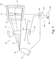
- Fig. 1
- eine schematische Darstellung eines Mikro-Computertomografiesystems;
- Fig. 2
- einen Längsquerschnitt durch eine Röntgenröhre in einer Ausführungsform, die als solche nicht zu der Erfindung, wie beansprucht, gehört;
- Fig. 3
- einen Querschnitt durch eine Röntgenröhre senkrecht zur Längsachse ;
- Fig. 4
- einen Längsquerschnitt durch eine Röntgenröhre in einer ersten Ausführungsform der Erfindung;
- Fig. 5
- einen Längsquerschnitt durch eine Röntgenröhre in einer weiteren Ausführungsform der Erfindung; und
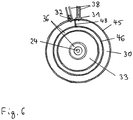
- Fig. 6
- einen Querschnitt durch eine Röntgenröhre senkrecht zur Längsachse in einer zur
Figur 3 alternativen Ausführungsform gemäß der Erfindung. - Die in
Figur 1 gezeigte Mikro-Computertomografievorrichtung umfasst ein Röntgensystem 10, das zur Aufnahme eines Satzes von Röntgenprojektionen einer Probe 13 eingerichtet ist. Zu diesem Zweck umfasst das Röntgensystem 10 eine Mikrofokus-Röntgenröhre 11, die Röntgenstrahlung 14 ausgehend von einem Brennpunkt oder Fokus 16 der Röntgenröhre 11 emittiert, einen bildgebenden Röntgendetektor 12 und einen Probenhalter 20, der vorzugsweise zum Rotieren der Probe 13 um eine vertikale Achse eingerichtet ist. Der Röntgendetektor 12 ist vorzugsweise ein Flächendetektor, insbesondere ein flat panel-Detektor, jedoch ist auch ein Zeilendetektor möglich. Ein Satz von Röntgenprojektionen der Probe 13 wird beispielsweise durch schrittweises Rotieren des Probenhalters 20 um jeweils einen definierten kleinen Winkelschritt und Aufnahme einer Röntgenprojektion bei jedem Rotationswinkel erhalten. Das Röntgensystem 10 ist nicht auf eine Rotation des Probenhalters 20 um eine vertikale Achse beschränkt. Alternativ können beispielsweise die Röntgenröhre 11 und der Röntgendetektor 12 um die feststehende Probe 13 rotiert werden. - Die Röntgenprojektionen werden aus dem Röntgendetektor 12 ausgelesen und an eine Computervorrichtung 41 übermittelt, wo aus dem aufgenommenen Satz von Röntgenprojektionen mittels eines grundsätzlich bekannten Rekonstruktionsalgorithmus rekonstruierte dreidimensionale Volumendaten der Probe 13 errechnet und beispielsweise auf einem Bildschirm 42 dargestellt werden. Die Computervorrichtung 41 kann, wie in
Fig. 1 gezeigt, ebenfalls zur Steuerung der Röntgenquelle 11, des Probenhalters 20 und des Röntgendetektors 12 eingerichtet sein; alternativ kann eine separate Steuervorrichtung vorgesehen sein. - Die Mikrofokus-Röntgenröhre 11 umfasst ein Kathodenelement 15, einen Wehnelt-Zylinder 21, eine Anode 19, eine vorzugsweise als elektromagnetische Linse ausgeführte Fokussierlinse 22 und ein Elektronenstrahl-Target 23. Des Weiteren kann eine weitere elektromagnetische Linse 25 vorgesehen sein, die vorzugsweise als Kondensorlinse eingerichtet ist, um den Elektronenstrahl 24 näherungsweise parallel auszurichten oder um eine Zwischenabbildung zu erzeugen; die Kondensorlinse 25 ist jedoch nicht zwingend erforderlich. Die Mikrofokus-Röntgenröhre 11 umfasst weiterhin zweckmäßigerweise eine nicht gezeigte Ablenkeinheit zur Strahllagejustierung. Die Mikrofokus-Röntgenröhre 11 ist so eingerichtet, dass der minimale Fokus bzw. Brennfleck auf dem Target 23 kleiner oder gleich 10 µm, vorzugsweise kleiner oder gleich 4 µm, noch weiter vorzugsweise kleiner oder gleich 2 µm beträgt.
- Die Mikrofokus-Röntgenröhre 11 umfasst des Weiteren ein Gehäuse 34, das aus mehreren Abschnitten zusammengesetzt sein kann. Insbesondere kann ein das Kathodenelement 15 aufnehmender und die Anode 19 bildender Gehäuseabschnitt 35, ein die Fokussierlinse 22 umgebender Gehäuseabschnitt 36 und gegebenenfalls ein dazwischen angeordneter mittlerer Gehäuseabschnitt 37, in dem beispielsweise die Kondensorlinse 25 angeordnet sein kann, vorgesehen sein. Das die Spule 33 umgebende Gehäuse 36 ist vorteilhafterweise frei von thermisch isolierenden, insbesondere nichtmetallischen Abschirmungen oder Schichten, die die Einstellung eines thermischen Gleichgewichts behindern würden.
- Die Röntgenröhre 11 umfasst eine ringförmige Kühlkammer 30, die einen Einlass 31 und einen Auslass 32 aufweist, die über Kühlmittelleitungen 38 mit einer nicht gezeigten Kühlmittelpumpe zu einem Kühlkreislauf verbindbar sind. Auf diese Weise kann ein flüssiges Kühlmittel, insbesondere Wasser oder Öl, durch die Kühlkammer 30 strömen, um dem Eintrag von Wärmeenergie aus verschiedenen internen und externen Wärmequellen und einer damit verbundenen Verschiebung des Fokuspunkts 16 relativ zu der Röhrenbefestigung 39 entgegenzuwirken. Die genannten Wärmequellen entstehen beispielsweise aufgrund des Auftreffens des Elektronenstrahls 24 auf dem Target 23, der Energiedissipation in der Elektronenoptik 22 und der Absorption thermischer Energie über die Oberfläche des Röhrengehäuses 34.
- Die Kühlkammer 30 ist ringförmig in sich geschlossen, wie am besten aus den
Figuren 3 und6 ersichtlich ist. In der Ausführungsform gemäßFigur 3 ist der flüssigkeitsdurchströmte Innenraum der Kühlkammer 30 umlaufend vollständig durchgängig. In dieser Ausführungsform sind Einlass 31 und Auslass 32 vorzugsweise um 180° versetzt zueinander, d.h. einander gegenüberliegend angeordnet, wie inFig. 3 gezeigt, damit die Kühlkammer 30 möglichst gleichförmig durchströmt wird und sich keine Vorzugsfließrichtung für das Kühlmedium ausbildet. - In der Ausführungsform gemäß
Figur 6 ist dagegen in der Kühlkammer 30 eine radiale Trennwand 48 vorgesehen, die den flüssigkeitsdurchströmten Innenraum der Kühlkammer 30 an einer Umfangsstelle unterbricht. In diesem Fall sind Einlass 31 und Auslass 32 zweckmäßigerweise im Bereich der Trennwand 48 auf entgegengesetzten Seiten derselben angeordnet, um eine vollständige Durchströmung der Kühlkammer 30 zu erreichen. In diesem Ausführungsbeispiel können Einlass und Auslass auch im Wesentlichen ohne Umfangsversatz, sondern stattdessen axial versetzt angeordnet sein. - Die Ausführungsform gemäß
Figur 6 verdeutlicht, dass das erfindungsgemäße Merkmal "im Wesentlichen rotationssymmetrisch" bedeutet: rotationssymmetrisch abgesehen von Ein- und Auslässen 31, 32 für das Kühlmittel, etwaigen Trennwänden 48 in der Kühlkammer und gegebenenfalls weiteren, die Rotationssymmetrie nicht wesentlich störenden Funktionselementen. Die Begriffe axial, radial und rotationssymmetrisch beziehen sich im Rahmen dieser Anmeldung auf die Längsachse der Röhre 11, welche durch die Mittelachse des Elektronenstrahls 24 zwischen der Kathode 15 und dem Target 23 definiert ist. - In der Ausführungsform gemäß
Figur 2 , die nicht zu der Erfindung, wie beansprucht, gehört, ist die Kühlkammer 30 um das Röhrengehäuse 34, insbesondere um den die Fokussierlinse 22 umgebenden Gehäuseabschnitt 36 angeordnet. In dieser Ausführungsform erstreckt sich die Kühlkammer 30 überwiegend axial, d.h. ihre axiale Erstreckung ist vorzugsweise mindestens doppelt so groß wie ihre radiale Erstreckung. Beispielsweise kann die axiale Erstreckung der Kühlkammer 30 an die axiale Erstreckung der Spule 33 der Fokussierlinse 22 angepasst sein. - In den Ausführungsformen gemäß
Figur 4 und 5 , die Ausführungsformen der Erfindung darstellen, ist die Kühlkammer 30 in dem Röhrengehäuse 34 angeordnet. In der inFigur 4 gezeigten Variante ist die Kühlkammer 30 außen an dem die Fokussierlinse 22 umgebenden Gehäuseabschnitt 36, hier in dem mittleren Gehäuseabschnitt 37, angeordnet. In der inFigur 5 gezeigten Variante ist die Kühlkammer 30 in dem die Fokussierlinse 22 umgebenden Gehäuseabschnitt 36 unmittelbar neben der Spule 33 angeordnet. In beiden Ausführungsformen erstreckt sich die Kühlkammer 30 überwiegend radial, d.h. ihre radiale Erstreckung ist vorzugsweise um mindestens 50% größer als ihre axiale Erstreckung. Beispielsweise kann die radiale Erstreckung der Kühlkammer 30 an die radiale Erstreckung der Spule 33 der Fokussierlinse 22 angepasst sein. - In den Ausführungsbeispielen gemäß
Figuren 4 und 5 ist die Kühlkammer 30 benachbart zu der Spule 33 der Fokussierlinse 22 angeordnet, da diese eine Hauptwärmequelle in der Röhre 11 darstellt. - In den Ausführungsformen gemäß
Figuren 3 bis 6 weist die Kühlkammer die bevorzugte Form eines Ringzylinders auf. Die radiale Außenwand 45 und die radiale Innenwand 46 der Kühlkammer 30 sind demnach zylindrisch geformt. Die zur Bildung einer geschlossenen Kühlkammer 30 erforderlichen Seitenwände 47 sind vorzugsweise scheibenförmig. - Die die Kühlkammer bildenden Wände 45, 46, 47 bestehen vorzugsweise aus einem Material mit einer guten Wärmeleitfähigkeit von mindestens 50 W/mK, insbesondere aus einem Material auf der Grundlage von Aluminium, Kupfer und/oder Messing.
- Wie aus den
Figuren 4 und 5 ersichtlich ist, ist die Querschnittsfläche der Kühlkammer 30 in einem Längsquerschnitt mehr als zehnmal so groß wie die Querschnittsfläche von mit der Kühlkammer 30 über die Anschlüsse 31, 32 zu verbindenden Kühlleitungen 38. Die Fließgeschwindigkeit des Kühlmediums in der Kühlkammer 30 ist daher vorzugsweise mehr als zehnmal kleiner als in den mit der Kühlkammer 30 über die Anschlüsse 31, 32 zu verbindenden Kühlleitungen 38. Die lichten Innenabmessungen der Kühlkammer 30 in einem Längsquerschnitt sind erheblich größer als die Wandstärken der Wände 45 bis 47, damit möglichst viel von dem zur Verfügung stehenden Bauraum als Kühlmittelvolumen nutzbar ist. Die vorgenannten Merkmale tragen zu einer effizienten Kühlung aufgrund größtmöglichen Kühlvolumens in der Kühlkammer 30 bei gegebener Baugröße bei. - Die Erfindung ist nicht auf einen Kühlmitteleinlass 31, einen Kühlmittelauslass 32 und gegebenenfalls eine Trennwand 48 beschränkt. Es sind weitere Ausführungsformen mit einer Mehrzahl von Kühlmitteleinlässen 31, einer Mehrzahl von Kühlmittelauslässen 32 und/oder einer Mehrzahl von Trennwänden 48 denkbar.
- Die Röhre 11 kann eine Mehrzahl von Kühlkammern 30 aufweisen, die beispielsweise axial versetzt zueinander angeordnet sein können.
- Die Kühlkammer 30 wurde vorstehend im Zusammenhang mit einer Röhre 11 mit Transmissionstarget beschrieben. Die Kühlkammer 30 kann jedoch ohne Weiteres alternativ in einer Röhre 11 mit Direktstrahlgeometrie, d.h. mit Reflektionstarget, vorteilhaft eingesetzt werden.
- Die Röhre 11 wurde vorstehend für die bevorzugte Anwendung in einer CT-Vorrichtung beschrieben. Es sind jedoch andere Anwendungen für die industrielle Röntgenprüfung oder Röntgenvermessung von Bauteilen denkbar. Im Allgemeinen kann die Röntgenröhre 11 vorteilhaft in einer hochauflösenden Röntgenvorrichtung mit einem bildgebenden Detektor verwendet werden.
Claims (8)
- Mikrofokus-Röntgenröhre (11) für eine hochauflösende Röntgenvorrichtung, umfassend ein Gehäuse (34), eine Elektronenstrahlquelle (15) zur Erzeugung eines Elektronenstrahls (14) und eine eine Spule (33) umfassende Fokussierlinse (22) zur Fokussierung des Elektronenstrahls (24) auf ein Target (23), wobei das Gehäuse (34) einen die Fokussierlinse (22) umgebenden Gehäuseabschnitt (36) aufweist und die Röntgenröhre (11) eine im Wesentlichen rotationssymmetrische, ringförmige Kühlkammer (30) aufweist, die zur Durchströmung mit einem flüssigen Kühlmedium eingerichtet ist,
dadurch gekennzeichnet, dass
die Kühlkammer (30) in dem Gehäuse, außen an dem die Fokussierlinse (22) umgebenden Gehäuseabschnitt (36), neben der Fokussierlinse (22) oder in dem die Fokussierlinse umgebenden Gehäuseabschnitt (36) unmittelbar neben der Spule (33) angeordnet ist,
wobei die Kühlkammer (30) sich überwiegend radial erstreckt, wobei die radiale Erstreckung der Kühlkammer (30) an die radiale Erstreckung der Spule (33) der Fokussierlinse (22) angepasst ist. - Mikrofokus-Röntgenröhre nach Anspruch 1, wobei die Querschnittsfläche der Kühlkammer (30) in einem Längsquerschnitt mindestens fünfmal so groß ist wie eine Querschnittsfläche von mit der Kühlkammer (30) zu verbindenden Kühlleitungen (38).
- Mikrofokus-Röntgenröhre nach einem der vorangehenden Ansprüche, wobei die lichten Innenabmessungen der Kühlkammer (30) in einem Längsquerschnitt größer sind als die Wandstärken der Kühlkammerwände (45-47).
- Mikrofokus-Röntgenröhre nach einem der vorangehenden Ansprüche, wobei die Kühlkammer (30) die Form eines Ringzylinders aufweist.
- Mikrofokus-Röntgenröhre nach einem der vorangehenden Ansprüche, wobei die Mikrofokus-Röntgenröhre einen Einlass (31) und einen Auslass (32) für das flüssige Kühlmedium aufweist und wobei der Einlass (31) und der Auslass (32) in einer Umfangsrichtung der Kühlkammer (30) versetzt zueinander angeordnet sind.
- Mikrofokus-Röntgenröhre nach einem der vorangehenden Ansprüche, wobei die Mikrofokus-Röntgenröhre einen Einlass (31) und einen Auslass (32) für das flüssige Kühlmedium aufweist und wobei der Einlass (31) und der Auslass (32) einander gegenüberliegend in Bezug auf die Röhrenachse angeordnet sind.
- Mikrofokus-Röntgenröhre nach einem der vorangehenden Ansprüche, wobei die Kühlkammer (30) bildende Wände (45-47) aus einem Material mit einer Wärmeleitfähigkeit von mindestens 50 W/mK bestehen.
- Mikrofokus-Röntgenröhre nach einem der vorangehenden Ansprüche, wobei die Kühlkammer (30) bildende Wände (45-47) aus einem Material auf der Grundlage von Aluminium, Kupfer und/oder Messing bestehen.
Applications Claiming Priority (1)
| Application Number | Priority Date | Filing Date | Title |
|---|---|---|---|
| PCT/EP2010/005273 WO2012025136A1 (de) | 2010-08-27 | 2010-08-27 | Mikrofokus-röntgenröhre für eine hochauflösende röntgenvorrichtung |
Publications (2)
| Publication Number | Publication Date |
|---|---|
| EP2609612A1 EP2609612A1 (de) | 2013-07-03 |
| EP2609612B1 true EP2609612B1 (de) | 2019-11-13 |
Family
ID=43904027
Family Applications (1)
| Application Number | Title | Priority Date | Filing Date |
|---|---|---|---|
| EP10749795.0A Active EP2609612B1 (de) | 2010-08-27 | 2010-08-27 | Mikrofokus-röntgenröhre für eine hochauflösende röntgenvorrichtung |
Country Status (5)
| Country | Link |
|---|---|
| US (1) | US9153408B2 (de) |
| EP (1) | EP2609612B1 (de) |
| JP (1) | JP5675987B2 (de) |
| CN (1) | CN103189955A (de) |
| WO (1) | WO2012025136A1 (de) |
Families Citing this family (10)
| Publication number | Priority date | Publication date | Assignee | Title |
|---|---|---|---|---|
| WO2013051594A1 (ja) * | 2011-10-04 | 2013-04-11 | 株式会社ニコン | X線装置、x線照射方法、及び構造物の製造方法 |
| EP2911179B1 (de) * | 2012-10-22 | 2017-11-29 | Shimadzu Corporation | Röntgenröhrenvorrichtung |
| CN103367083A (zh) * | 2013-07-10 | 2013-10-23 | 杭州电子科技大学 | 小束斑x射线设备 |
| CN103578886B (zh) * | 2013-11-12 | 2016-08-17 | 陆振民 | 电磁波发生装置 |
| CN107251094B (zh) * | 2014-08-16 | 2021-01-08 | Fei公司 | 用于材料特性描述的断层图像重建 |
| CN105047509B (zh) * | 2015-07-24 | 2017-03-29 | 中国科学院电工研究所 | 大束流电子束打靶微束斑x射线源的聚焦装置 |
| EP3389055B1 (de) * | 2017-04-11 | 2025-09-24 | Siemens Healthineers AG | Röntgeneinrichtung zur erzeugung von hochenergetischer röntgenstrahlung |
| DE102018107952B4 (de) * | 2018-04-04 | 2024-01-04 | Comet Ag | Blendenhalter für eine Objektivblende einer Röntgenröhre, Objektivblende und Röntgenröhre |
| CN109087838A (zh) * | 2018-06-19 | 2018-12-25 | 广州市昊志影像科技有限公司 | 一种基于碳纳米管场发射的微焦点x射线管 |
| US11721515B2 (en) | 2021-01-22 | 2023-08-08 | Hamamatsu Photonics K.K. | X-ray module |
Citations (1)
| Publication number | Priority date | Publication date | Assignee | Title |
|---|---|---|---|---|
| EP0096824A1 (de) * | 1982-06-16 | 1983-12-28 | feinfocus Verwaltungs GmbH & Co. KG | Feinfokus-Röntgenröhre und Verfahren zur Bildung eines Mikrofokus der Elektronenemission einer Röntgenröhren-Glühkathode |
Family Cites Families (32)
| Publication number | Priority date | Publication date | Assignee | Title |
|---|---|---|---|---|
| NL16090C (de) * | 1924-06-18 | |||
| US1917099A (en) * | 1929-10-18 | 1933-07-04 | Gen Electric | x-ray tube |
| US2356645A (en) * | 1943-02-08 | 1944-08-22 | Gen Electric X Ray Corp | X-ray tube |
| BE474550A (de) * | 1945-09-18 | |||
| JP2920390B2 (ja) * | 1989-11-08 | 1999-07-19 | 株式会社日立製作所 | 電子レンズの冷却系 |
| US6249569B1 (en) * | 1998-12-22 | 2001-06-19 | General Electric Company | X-ray tube having increased cooling capabilities |
| JP2001006592A (ja) * | 1999-06-24 | 2001-01-12 | Nikon Corp | 冷却装置、荷電粒子線露光装置及び半導体装置の製造方法 |
| US6438207B1 (en) * | 1999-09-14 | 2002-08-20 | Varian Medical Systems, Inc. | X-ray tube having improved focal spot control |
| US6580780B1 (en) * | 2000-09-07 | 2003-06-17 | Varian Medical Systems, Inc. | Cooling system for stationary anode x-ray tubes |
| US6430263B1 (en) * | 2000-12-01 | 2002-08-06 | Koninklijke Philips Electronics, N.V. | Cold-plate window in a metal-frame x-ray insert |
| JP3880897B2 (ja) * | 2002-07-18 | 2007-02-14 | 株式会社東芝 | 回転陽極型x線管 |
| JP3950389B2 (ja) | 2002-08-14 | 2007-08-01 | 浜松ホトニクス株式会社 | X線管 |
| DE10320361B3 (de) * | 2003-05-07 | 2004-12-16 | Siemens Ag | Vorrichtung mit einem in einem Fluid eingetauchten Drehkörper, insbesondere Röntgenstrahler |
| US6852982B1 (en) | 2003-07-14 | 2005-02-08 | Fei Company | Magnetic lens |
| JP4987299B2 (ja) * | 2003-10-17 | 2012-07-25 | 株式会社東芝 | X線装置 |
| WO2005069341A2 (en) * | 2004-01-13 | 2005-07-28 | Koninklijke Philips Electronics, N.V. | Composite frame for x-ray tubes |
| US6977991B1 (en) * | 2004-01-13 | 2005-12-20 | Siemens Aktiengesellschaft | Cooling arrangement for an X-ray tube having an external electron beam deflector |
| JP4698608B2 (ja) | 2004-01-13 | 2011-06-08 | コーニンクレッカ フィリップス エレクトロニクス エヌ ヴィ | X線管冷却環 |
| WO2005069342A2 (en) * | 2004-01-13 | 2005-07-28 | Koninklijke Philips Electronics, N.V. | Liquid flow sensor for x-ray tubes |
| DE102005049270B4 (de) * | 2005-10-14 | 2012-02-16 | Siemens Ag | Drehkolbenröhre mit einer von Kühlflüssigkeit durchströmten Kühleinrichtung sowie Verwendung der Kühlflüssigkeit |
| DE102005049455B4 (de) * | 2005-10-15 | 2007-11-22 | Ziehm Imaging Gmbh | Wärmetauscher für einen Einkessel-Generator einer Röntgendiagnostikeinrichtung mit einer Drehanodenröhre mit Glasgehäuse |
| JP3887395B2 (ja) | 2005-11-25 | 2007-02-28 | 株式会社東芝 | X線発生装置 |
| FR2895831B1 (fr) | 2006-01-03 | 2009-06-12 | Alcatel Sa | Source compacte a faisceau de rayons x de tres grande brillance |
| JP2007294420A (ja) * | 2006-03-29 | 2007-11-08 | Toshiba Corp | 回転陽極x線管装置 |
| US7520672B2 (en) * | 2006-03-31 | 2009-04-21 | General Electric Company | Cooling assembly for an X-ray tube |
| JP4908341B2 (ja) * | 2006-09-29 | 2012-04-04 | 株式会社東芝 | 回転陽極型x線管装置 |
| US7508916B2 (en) * | 2006-12-08 | 2009-03-24 | General Electric Company | Convectively cooled x-ray tube target and method of making same |
| EP1970935B1 (de) | 2007-03-14 | 2011-01-12 | ICT, Integrated Circuit Testing Gesellschaft für Halbleiterprüftechnik mbH | Kühlung der Spule einer Magnetlinse |
| JP5363721B2 (ja) * | 2007-11-15 | 2013-12-11 | 株式会社日立製作所 | 荷電粒子線装置における冷却装置 |
| DE102008038582A1 (de) * | 2008-08-21 | 2010-02-25 | Siemens Aktiengesellschaft | Röntgenstrahler |
| US8009805B2 (en) * | 2009-06-09 | 2011-08-30 | General Electric Company | Rotating union for a liquid cooled rotating X-ray target |
| US8009806B2 (en) * | 2009-07-13 | 2011-08-30 | General Electric Company | Apparatus and method of cooling a liquid metal bearing in an x-ray tube |
-
2010
- 2010-08-27 EP EP10749795.0A patent/EP2609612B1/de active Active
- 2010-08-27 JP JP2013525146A patent/JP5675987B2/ja not_active Expired - Fee Related
- 2010-08-27 US US13/818,994 patent/US9153408B2/en active Active
- 2010-08-27 CN CN2010800688420A patent/CN103189955A/zh active Pending
- 2010-08-27 WO PCT/EP2010/005273 patent/WO2012025136A1/de not_active Ceased
Patent Citations (1)
| Publication number | Priority date | Publication date | Assignee | Title |
|---|---|---|---|---|
| EP0096824A1 (de) * | 1982-06-16 | 1983-12-28 | feinfocus Verwaltungs GmbH & Co. KG | Feinfokus-Röntgenröhre und Verfahren zur Bildung eines Mikrofokus der Elektronenemission einer Röntgenröhren-Glühkathode |
Non-Patent Citations (3)
| Title |
|---|
| LOPES R T ET AL: "Evaluation of a Microtomography System with an X-ray Microfocus Tube", APPLIED RADIATION AND ISOTOPES, ELSEVIER, OXFORD, GB, vol. 48, no. 10-12, 12 October 1997 (1997-10-12), pages 1437 - 1442, XP004101732, ISSN: 0969-8043, DOI: 10.1016/S0969-8043(97)00256-X * |
| PUGH D J ET AL: "An electron source for a microfocus X-ray tube incorporating a single pole magnetic lens and novel focusing system", DEVELOPMENTS IN ELECTRON MICROSCOPY AND ANALYSIS 197712-14 SEPT. 1977 GLASGOW, UK, UK, 12 September 1977 (1977-09-12), pages 29 - 32, XP009193427, ISBN: 0-85498-127-6 * |
| SIMONS ET AL: "Quantitative characterization of coal by means of microfocal X-ray computed microtomography (CMT) and color image analysis (CIA)", INTERNATIONAL JOURNAL OF COAL GEOLOGY, ELSEVIER, AMSTERDAM, NL, vol. 34, no. 1-2, 1 October 1997 (1997-10-01), pages 69 - 88, XP005876044, ISSN: 0166-5162, DOI: 10.1016/S0166-5162(97)00011-6 * |
Also Published As
| Publication number | Publication date |
|---|---|
| CN103189955A (zh) | 2013-07-03 |
| US20130208870A1 (en) | 2013-08-15 |
| EP2609612A1 (de) | 2013-07-03 |
| US9153408B2 (en) | 2015-10-06 |
| JP5675987B2 (ja) | 2015-02-25 |
| WO2012025136A1 (de) | 2012-03-01 |
| JP2013538421A (ja) | 2013-10-10 |
Similar Documents
| Publication | Publication Date | Title |
|---|---|---|
| EP2609612A1 (de) | Mikrofokus-röntgenröhre für eine hochauflösende röntgenvorrichtung | |
| EP1852709B1 (de) | Gekühlter NMR Probenkopf mit flexibler gekühlter Verbindungsleitung | |
| DE102004018765A1 (de) | Stationäres Computertomographiesystem mit kompakter Röntgenquellen-Baueinheit | |
| EP3387274B1 (de) | Lagerbock zur aufnahme eines lagers für eine rolle | |
| EP2473298B1 (de) | Rolle und rollenanordnung für eine stranggiessanlage | |
| DE102010049953A1 (de) | Anordnung mit Vorrichtungen zu integrierter Kühlung und/oder Heizung sowie ein Verfahren zur integrierten Beheizung oder Kühlung | |
| DE102010029080B4 (de) | Temperiereinrichtung für ein NMR-Probenröhrchen und Verfahren zur Temperierung eines NMR-Probenröhrchens | |
| DE102013107736A1 (de) | Röntgenprüfvorrichtung für die Materialprüfung und Verfahren zur Erzeugung hochaufgelöster Projektionen eines Prüflings mittels Röntgenstrahlen | |
| EP2486357B1 (de) | Kühleinrichtung für einen bei erhöhter umgebungstemperatur einsetzbaren sensor | |
| WO2020057699A1 (de) | Kühlkörper für einen elektrischen motor, elektrischer motor und verfahren zum kühlen des motors | |
| DE1564967A1 (de) | Kernreaktor-Brennelement | |
| DE102016218772A1 (de) | Verbesserte Temperierung eines NMR-MAS-Rotors | |
| EP2935152A1 (de) | Thermisches abschirmsystem | |
| DE102012217567A1 (de) | Kühleinrichtung einer Gantry eines Computertomographen | |
| EP3881088B1 (de) | Temperierung für ein nmr-probenröhrchen | |
| DE102005060242B4 (de) | Verfahren und Aufbau zur Milderung der elektrischen Beanspruchung an Hochspannungsisolatoren in Röntgenröhren | |
| DE1149831B (de) | Roehrensystem zur Abfuhr der Waerme aus Kernreaktoren | |
| DE102010054816B3 (de) | Stabanode einer Mikrofocus-Röntgenröhre | |
| DE102007008349A1 (de) | Anordnung zur Röntgen-Computertomographie | |
| DE2726195C3 (de) | Magnetische Objektivlinse für unter Vakuum arbeitende Korpuskularstrahlgeräte, insbesondere Objektivlinse für Elektronenmikroskope | |
| DE102021117606A1 (de) | Empfängervorrichtung für solarstrahlung mit einem behälter zum aufheizen eines wärmeträgermediums in einem solarthermischen kraftwerk | |
| DE102012217739A1 (de) | Kühleinrichtung einer Gantry eines Computertomographen | |
| DE1207518B (de) | Brennelement fuer Druckrohr-Kernreaktoren | |
| DE102019219551A1 (de) | Sensor-Anordnung | |
| DE102024117485A1 (de) | Fluidgekühltes optikmodul, laseranlage damit, verfahren zum betreiben einer laseranlage, verfahren zum erzeugen eines plasmas eines targetmaterials zum erzeugen von sekundär- strahlung und herstellungsverfahren zum herstellen von mikrochips oder halbleiter-zwischenprodukten |
Legal Events
| Date | Code | Title | Description |
|---|---|---|---|
| PUAI | Public reference made under article 153(3) epc to a published international application that has entered the european phase |
Free format text: ORIGINAL CODE: 0009012 |
|
| 17P | Request for examination filed |
Effective date: 20130207 |
|
| AK | Designated contracting states |
Kind code of ref document: A1 Designated state(s): AL AT BE BG CH CY CZ DE DK EE ES FI FR GB GR HR HU IE IS IT LI LT LU LV MC MK MT NL NO PL PT RO SE SI SK SM TR |
|
| DAX | Request for extension of the european patent (deleted) | ||
| STAA | Information on the status of an ep patent application or granted ep patent |
Free format text: STATUS: EXAMINATION IS IN PROGRESS |
|
| 17Q | First examination report despatched |
Effective date: 20170220 |
|
| GRAP | Despatch of communication of intention to grant a patent |
Free format text: ORIGINAL CODE: EPIDOSNIGR1 |
|
| STAA | Information on the status of an ep patent application or granted ep patent |
Free format text: STATUS: GRANT OF PATENT IS INTENDED |
|
| INTG | Intention to grant announced |
Effective date: 20190517 |
|
| GRAS | Grant fee paid |
Free format text: ORIGINAL CODE: EPIDOSNIGR3 |
|
| GRAA | (expected) grant |
Free format text: ORIGINAL CODE: 0009210 |
|
| STAA | Information on the status of an ep patent application or granted ep patent |
Free format text: STATUS: THE PATENT HAS BEEN GRANTED |
|
| AK | Designated contracting states |
Kind code of ref document: B1 Designated state(s): AL AT BE BG CH CY CZ DE DK EE ES FI FR GB GR HR HU IE IS IT LI LT LU LV MC MK MT NL NO PL PT RO SE SI SK SM TR |
|
| REG | Reference to a national code |
Ref country code: GB Ref legal event code: FG4D Free format text: NOT ENGLISH |
|
| REG | Reference to a national code |
Ref country code: CH Ref legal event code: EP Ref country code: AT Ref legal event code: REF Ref document number: 1202537 Country of ref document: AT Kind code of ref document: T Effective date: 20191115 |
|
| REG | Reference to a national code |
Ref country code: DE Ref legal event code: R096 Ref document number: 502010016371 Country of ref document: DE |
|
| REG | Reference to a national code |
Ref country code: IE Ref legal event code: FG4D Free format text: LANGUAGE OF EP DOCUMENT: GERMAN |
|
| REG | Reference to a national code |
Ref country code: NL Ref legal event code: MP Effective date: 20191113 |
|
| REG | Reference to a national code |
Ref country code: LT Ref legal event code: MG4D |
|
| PG25 | Lapsed in a contracting state [announced via postgrant information from national office to epo] |
Ref country code: LV Free format text: LAPSE BECAUSE OF FAILURE TO SUBMIT A TRANSLATION OF THE DESCRIPTION OR TO PAY THE FEE WITHIN THE PRESCRIBED TIME-LIMIT Effective date: 20191113 Ref country code: SE Free format text: LAPSE BECAUSE OF FAILURE TO SUBMIT A TRANSLATION OF THE DESCRIPTION OR TO PAY THE FEE WITHIN THE PRESCRIBED TIME-LIMIT Effective date: 20191113 Ref country code: NL Free format text: LAPSE BECAUSE OF FAILURE TO SUBMIT A TRANSLATION OF THE DESCRIPTION OR TO PAY THE FEE WITHIN THE PRESCRIBED TIME-LIMIT Effective date: 20191113 Ref country code: ES Free format text: LAPSE BECAUSE OF FAILURE TO SUBMIT A TRANSLATION OF THE DESCRIPTION OR TO PAY THE FEE WITHIN THE PRESCRIBED TIME-LIMIT Effective date: 20191113 Ref country code: BG Free format text: LAPSE BECAUSE OF FAILURE TO SUBMIT A TRANSLATION OF THE DESCRIPTION OR TO PAY THE FEE WITHIN THE PRESCRIBED TIME-LIMIT Effective date: 20200213 Ref country code: FI Free format text: LAPSE BECAUSE OF FAILURE TO SUBMIT A TRANSLATION OF THE DESCRIPTION OR TO PAY THE FEE WITHIN THE PRESCRIBED TIME-LIMIT Effective date: 20191113 Ref country code: PL Free format text: LAPSE BECAUSE OF FAILURE TO SUBMIT A TRANSLATION OF THE DESCRIPTION OR TO PAY THE FEE WITHIN THE PRESCRIBED TIME-LIMIT Effective date: 20191113 Ref country code: LT Free format text: LAPSE BECAUSE OF FAILURE TO SUBMIT A TRANSLATION OF THE DESCRIPTION OR TO PAY THE FEE WITHIN THE PRESCRIBED TIME-LIMIT Effective date: 20191113 Ref country code: GR Free format text: LAPSE BECAUSE OF FAILURE TO SUBMIT A TRANSLATION OF THE DESCRIPTION OR TO PAY THE FEE WITHIN THE PRESCRIBED TIME-LIMIT Effective date: 20200214 Ref country code: PT Free format text: LAPSE BECAUSE OF FAILURE TO SUBMIT A TRANSLATION OF THE DESCRIPTION OR TO PAY THE FEE WITHIN THE PRESCRIBED TIME-LIMIT Effective date: 20200313 Ref country code: NO Free format text: LAPSE BECAUSE OF FAILURE TO SUBMIT A TRANSLATION OF THE DESCRIPTION OR TO PAY THE FEE WITHIN THE PRESCRIBED TIME-LIMIT Effective date: 20200213 |
|
| PG25 | Lapsed in a contracting state [announced via postgrant information from national office to epo] |
Ref country code: HR Free format text: LAPSE BECAUSE OF FAILURE TO SUBMIT A TRANSLATION OF THE DESCRIPTION OR TO PAY THE FEE WITHIN THE PRESCRIBED TIME-LIMIT Effective date: 20191113 Ref country code: IS Free format text: LAPSE BECAUSE OF FAILURE TO SUBMIT A TRANSLATION OF THE DESCRIPTION OR TO PAY THE FEE WITHIN THE PRESCRIBED TIME-LIMIT Effective date: 20200313 |
|
| PG25 | Lapsed in a contracting state [announced via postgrant information from national office to epo] |
Ref country code: AL Free format text: LAPSE BECAUSE OF FAILURE TO SUBMIT A TRANSLATION OF THE DESCRIPTION OR TO PAY THE FEE WITHIN THE PRESCRIBED TIME-LIMIT Effective date: 20191113 |
|
| PG25 | Lapsed in a contracting state [announced via postgrant information from national office to epo] |
Ref country code: RO Free format text: LAPSE BECAUSE OF FAILURE TO SUBMIT A TRANSLATION OF THE DESCRIPTION OR TO PAY THE FEE WITHIN THE PRESCRIBED TIME-LIMIT Effective date: 20191113 Ref country code: CZ Free format text: LAPSE BECAUSE OF FAILURE TO SUBMIT A TRANSLATION OF THE DESCRIPTION OR TO PAY THE FEE WITHIN THE PRESCRIBED TIME-LIMIT Effective date: 20191113 Ref country code: EE Free format text: LAPSE BECAUSE OF FAILURE TO SUBMIT A TRANSLATION OF THE DESCRIPTION OR TO PAY THE FEE WITHIN THE PRESCRIBED TIME-LIMIT Effective date: 20191113 Ref country code: DK Free format text: LAPSE BECAUSE OF FAILURE TO SUBMIT A TRANSLATION OF THE DESCRIPTION OR TO PAY THE FEE WITHIN THE PRESCRIBED TIME-LIMIT Effective date: 20191113 |
|
| REG | Reference to a national code |
Ref country code: DE Ref legal event code: R097 Ref document number: 502010016371 Country of ref document: DE |
|
| PG25 | Lapsed in a contracting state [announced via postgrant information from national office to epo] |
Ref country code: SK Free format text: LAPSE BECAUSE OF FAILURE TO SUBMIT A TRANSLATION OF THE DESCRIPTION OR TO PAY THE FEE WITHIN THE PRESCRIBED TIME-LIMIT Effective date: 20191113 Ref country code: SM Free format text: LAPSE BECAUSE OF FAILURE TO SUBMIT A TRANSLATION OF THE DESCRIPTION OR TO PAY THE FEE WITHIN THE PRESCRIBED TIME-LIMIT Effective date: 20191113 |
|
| PLBE | No opposition filed within time limit |
Free format text: ORIGINAL CODE: 0009261 |
|
| STAA | Information on the status of an ep patent application or granted ep patent |
Free format text: STATUS: NO OPPOSITION FILED WITHIN TIME LIMIT |
|
| 26N | No opposition filed |
Effective date: 20200814 |
|
| PG25 | Lapsed in a contracting state [announced via postgrant information from national office to epo] |
Ref country code: SI Free format text: LAPSE BECAUSE OF FAILURE TO SUBMIT A TRANSLATION OF THE DESCRIPTION OR TO PAY THE FEE WITHIN THE PRESCRIBED TIME-LIMIT Effective date: 20191113 |
|
| PG25 | Lapsed in a contracting state [announced via postgrant information from national office to epo] |
Ref country code: IT Free format text: LAPSE BECAUSE OF FAILURE TO SUBMIT A TRANSLATION OF THE DESCRIPTION OR TO PAY THE FEE WITHIN THE PRESCRIBED TIME-LIMIT Effective date: 20191113 |
|
| PG25 | Lapsed in a contracting state [announced via postgrant information from national office to epo] |
Ref country code: MC Free format text: LAPSE BECAUSE OF FAILURE TO SUBMIT A TRANSLATION OF THE DESCRIPTION OR TO PAY THE FEE WITHIN THE PRESCRIBED TIME-LIMIT Effective date: 20191113 |
|
| PG25 | Lapsed in a contracting state [announced via postgrant information from national office to epo] |
Ref country code: LU Free format text: LAPSE BECAUSE OF NON-PAYMENT OF DUE FEES Effective date: 20200827 |
|
| REG | Reference to a national code |
Ref country code: BE Ref legal event code: MM Effective date: 20200831 |
|
| PG25 | Lapsed in a contracting state [announced via postgrant information from national office to epo] |
Ref country code: BE Free format text: LAPSE BECAUSE OF NON-PAYMENT OF DUE FEES Effective date: 20200831 Ref country code: IE Free format text: LAPSE BECAUSE OF NON-PAYMENT OF DUE FEES Effective date: 20200827 |
|
| REG | Reference to a national code |
Ref country code: AT Ref legal event code: MM01 Ref document number: 1202537 Country of ref document: AT Kind code of ref document: T Effective date: 20200827 |
|
| PG25 | Lapsed in a contracting state [announced via postgrant information from national office to epo] |
Ref country code: AT Free format text: LAPSE BECAUSE OF NON-PAYMENT OF DUE FEES Effective date: 20200827 |
|
| PG25 | Lapsed in a contracting state [announced via postgrant information from national office to epo] |
Ref country code: TR Free format text: LAPSE BECAUSE OF FAILURE TO SUBMIT A TRANSLATION OF THE DESCRIPTION OR TO PAY THE FEE WITHIN THE PRESCRIBED TIME-LIMIT Effective date: 20191113 Ref country code: MT Free format text: LAPSE BECAUSE OF FAILURE TO SUBMIT A TRANSLATION OF THE DESCRIPTION OR TO PAY THE FEE WITHIN THE PRESCRIBED TIME-LIMIT Effective date: 20191113 Ref country code: CY Free format text: LAPSE BECAUSE OF FAILURE TO SUBMIT A TRANSLATION OF THE DESCRIPTION OR TO PAY THE FEE WITHIN THE PRESCRIBED TIME-LIMIT Effective date: 20191113 |
|
| PG25 | Lapsed in a contracting state [announced via postgrant information from national office to epo] |
Ref country code: MK Free format text: LAPSE BECAUSE OF FAILURE TO SUBMIT A TRANSLATION OF THE DESCRIPTION OR TO PAY THE FEE WITHIN THE PRESCRIBED TIME-LIMIT Effective date: 20191113 |
|
| P01 | Opt-out of the competence of the unified patent court (upc) registered |
Effective date: 20230526 |
|
| PGFP | Annual fee paid to national office [announced via postgrant information from national office to epo] |
Ref country code: DE Payment date: 20250724 Year of fee payment: 16 |
|
| PGFP | Annual fee paid to national office [announced via postgrant information from national office to epo] |
Ref country code: GB Payment date: 20250724 Year of fee payment: 16 |
|
| PGFP | Annual fee paid to national office [announced via postgrant information from national office to epo] |
Ref country code: FR Payment date: 20250725 Year of fee payment: 16 |
|
| PGFP | Annual fee paid to national office [announced via postgrant information from national office to epo] |
Ref country code: CH Payment date: 20250901 Year of fee payment: 16 |