EP2608333A2 - Leiste; Verfahren zur Herstellung einer Leiste - Google Patents
Leiste; Verfahren zur Herstellung einer Leiste Download PDFInfo
- Publication number
- EP2608333A2 EP2608333A2 EP12008674.9A EP12008674A EP2608333A2 EP 2608333 A2 EP2608333 A2 EP 2608333A2 EP 12008674 A EP12008674 A EP 12008674A EP 2608333 A2 EP2608333 A2 EP 2608333A2
- Authority
- EP
- European Patent Office
- Prior art keywords
- strip
- profile housing
- edge
- unit
- profile
- Prior art date
- Legal status (The legal status is an assumption and is not a legal conclusion. Google has not performed a legal analysis and makes no representation as to the accuracy of the status listed.)
- Granted
Links
Images




Classifications
-
- H—ELECTRICITY
- H02—GENERATION; CONVERSION OR DISTRIBUTION OF ELECTRIC POWER
- H02G—INSTALLATION OF ELECTRIC CABLES OR LINES, OR OF COMBINED OPTICAL AND ELECTRIC CABLES OR LINES
- H02G3/00—Installations of electric cables or lines or protective tubing therefor in or on buildings, equivalent structures or vehicles
- H02G3/02—Details
- H02G3/08—Distribution boxes; Connection or junction boxes
- H02G3/12—Distribution boxes; Connection or junction boxes for flush mounting
- H02G3/128—Distribution boxes; Connection or junction boxes for flush mounting in plinths, channels, raceways or similar
Definitions
- the invention relates to a strip, according to the preamble of claim 1, and a method for producing a strip, according to the preamble of claim 11, wherein the strip at least one installation unit (eg, power outlet, IEC device, switch, electronic unit, fuse holder or the like). having.
- installation unit eg, power outlet, IEC device, switch, electronic unit, fuse holder or the like.
- a power supply unit which has a plurality of arranged in an insulating profile busbars.
- the busbars serve to make contact with the installation units present in the power supply unit.
- the power supply unit has a profile housing with a U-shaped cross-section. In the interior of the profile housing are elevations, which correspond to the connection of the mounting unit with the power supply unit with a groove arranged on the mounting unit.
- the disadvantage is that even a slight tilting of the mounting unit causes the legs of the U-shaped cross section to be forced apart, so that a seizing of the installation units is no longer ensured.
- the installation units must be successively inserted from the side into the socket profile, so that the time required for an assembly of the power supply unit is dependent on the number of installation units to be inserted.
- the strip according to the invention, with the characterizing features of claim 1, and the inventive method for producing a strip, with the characterizing features of claim 11, have the advantage that the strip according to the invention, which has at least one mounting unit and a profile housing, in the the mounting unit is at least partially accommodated, wherein an edge of the mounting unit facing side of the profile housing has an inner side and an outer side, wherein on the mounting unit a profile housing facing edge is arranged, which is an outer, in operative connection with the outside of the edge of the profile housing , Part and an inner, with the inside of the edge of the profile housing operatively connected, part, so that a pressing apart of the edges of the profile housing is avoided.
- the edge of the mounting unit facing the profile housing has at least one recess for at least partially receiving the edge of the profile housing.
- the inner part of the edge of the mounting unit at its the inside of the profile housing facing side and / or the inside of the edge of the profile housing at least one survey.
- the survey is a latching hook.
- the inner part of the edge of the mounting unit on its the inside of the profile housing facing side and / or the inside of the edge of the profile housing at least one recess.
- the recess is a groove
- the strip has an end cap closed by an end cap.
- the end cap is connected by a latching with the profile housing.
- a milled ridge in the end of the profile housing also allows the end caps to lock without tools. With tolerances difficult profile lengths, the end cap can be secured laterally by attached holes without locking.
- the mounting unit is a socket (5), a switch, an electronics unit, a fuse holder, a cover (6) or the like.
- the strip (1) is a socket strip, a switch strip, a power distribution unit (PDU) or the like.
- the at least two housed in a profile housing mounting units are electrically connected, wherein in a first method step, the installation units are lined up side by side such that an electrical connection of a mounting unit for the electrical connection is accessible to after the electrical connection, the profile housing to produce the strip over the mounting units, that is Profile housing for producing the strip with the installation units locked.
- connection of the profile housing with the mounting units takes place without tools.
- the strip to be produced is a strip according to one of claims 1 to 10.
- Fig. 1 shows a side view of a strip according to the invention 1.
- the strip 1 has a profile housing, which consists of a bottom 2, two side walls 3 and two end faces 4.
- a socket 5 and a cover 6 are arranged as installation units in the strip 1.
- the front side 4 is closed with an end cap 7.
- Fig. 2 shows a cross section of a profile housing 8 of a strip according to the invention along the line GG Fig. 1 , At an edge 9 of the side walls 3, which has an outside 10 and an inside 11, a recess 12 is arranged in which lock the modular mounting units securely. At the edge of the side wall 3, there is also an abutment 13 for securing the mounting elements.
- Fig. 3 shows a sectional view of the bar 1 according to the invention along the line AA Fig. 1 ,
- Fig. 4 shows an enlarged detail F Fig. 3 , In this case, the connection of an installation unit 14 with the profile housing 8 can be seen.
- the mounting element 14 has latching hooks 15 and abutment 10, which correspond to the recesses 12 and the abutments 13 of the profile housing 8, so that the mounting unit 14 can be securely locked in the profile housing 8.
- latching hooks 15, recesses 12 and the abutment 13 and 16 By the combination of latching hooks 15, recesses 12 and the abutment 13 and 16, the edges 9 of the profile housing 8 are braced against each other.
- Fig. 5 shows a plan view of the strip 1 according to the invention Fig. 1 .
- the modular sockets 5 may have different country versions. Also for the covers 6, there may be different lengths and designs.
- Fig. 6 shows a sectional view of the bar according to the invention along the line BB Fig. 5 ,
- Fig. 7 shows a sectional view along the line DD Fig. 5 .
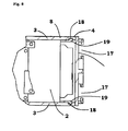
- Fig. 8 shows an enlarged section E from Fig. 7
- the end cap 7 preferably has guides 17 which are adapted to receive a Not shown mounting bracket (Anschraubwinkel), as it is used eg in IT racks, serve, whereby the bar are mounted without tools in an IT rack.
- a Not shown mounting bracket Anschraubwinkel
- On the front side 4 is a milled profile groove 18 into which a latching hook 19 of the end cap 7 can be latched, thereby connecting the end cap 7 with the profile housing 8, whereby screwing the end cap 7 is unnecessary.
- Fig. 9 shows a perspective view of the strip 1 according to the invention according Fig. 1 .
- This system has the advantage that the mounting units lying on the head, for example, can already be wired to then simply the profile housing 8 over put on until the locking takes place.
- the invention also includes a method for manufacturing a bar (eg power distribution unit (PDU)).
- PDU power distribution unit
- Fig. 10 shows an enlarged section H from Fig. 9 .
- Fig. 11 shows an end cap 7 with its latching hooks 19 and abutments 20th
Landscapes
- Engineering & Computer Science (AREA)
- Architecture (AREA)
- Civil Engineering (AREA)
- Structural Engineering (AREA)
- Casings For Electric Apparatus (AREA)
- Coating With Molten Metal (AREA)
Abstract
Description
- Die Erfindung geht aus von einer Leiste, nach der Gattung des Anspruchs 1, und einem Verfahren zur Herstellung einer Leiste, nach der Gattung des Anspruchs 11, wobei die Leiste mindestens eine Einbaueinheit (z.B. Steckdose, Kaltgeräteeinsatz, Schalter; Elektronikeinheit, Sicherungshalter odgl.) aufweist.
- In der Offenlegungsschrift
DE 103 07 353 A1 wird eine Stromzuführungseinheit beschrieben, die mehrere in einem Isolierprofil angeordnete Stromschienen aufweist. Die Stromschienen dienen dabei zur Kontaktierung der in der Stromzuführungseinheit vorhandenen Einbaueinheiten. Die Stromzuführungseinheit weist ein Profilgehäuse mit einem U-förmigen Querschnitt auf. Im Inneren des Profilgehäuses befinden sich Erhebungen, die zur Verbindung der Einbaueinheit mit der Stromzuführungseinheit mit einer an der Einbaueinheit angeordneten Nut korrespondieren. Nachteilig ist, dass schon ein leichtes Verkanten der Einbaueinheit dazu führt, dass die Schenkel des U-förmigen Querschnittes auseinandergedrückt werden, so dass ein Festsitzen der Einbaueinheiten nicht mehr sicher gestellt ist. Zusätzlich ist nachteilig zu bewerten, dass die Einbaueinheiten nacheinander von der Seite in das Steckdosenprofil eingeschoben werden müssen, so dass die für einen Zusammenbau der Stromzuführungseinheit benötigte Zeit abhängig von der Anzahl der einzuschiebenden Einbaueinheiten ist. - Die erfindungsgemäße Leiste, mit dem kennzeichnenden Merkmale des Anspruchs 1, und das erfindungsgemäße Verfahren zur Herstellung einer Leiste, mit den kennzeichnenden Merkmalen des Anspruchs 11, haben demgegenüber den Vorteil, dass die erfindungsgemäße Leiste, die mindestens eine Einbaueinheit und ein Profilgehäuse aufweist, in das die Einbaueinheit zumindest teilweise aufgenommen ist, wobei ein Rand einer der Einbaueinheit zugewandten Seite des Profilgehäuses eine Innenseite und eine Außenseite aufweist, wobei an der Einbaueinheit ein dem Profilgehäuse zugewandter Rand angeordnet ist, der einen äußeren, mit der Außenseite des Randes des Profilgehäuses in Wirkverbindung stehenden, Teil und einen inneren, mit der Innenseite des Randes des Profilgehäuses in Wirkverbindung stehenden, Teil aufweist, so dass ein Auseinanderdrücken der Ränder des Profilgehäuses vermieden wird. Durch diese Profilgeometrie ist ein sicheres Verrasten der Einbaueinheiten von oben möglich, so dass die Einbaueinheiten von oben in das Profilgehäuse eingesteckt werden können. Der nicht mehr benötigte Anschraubsteg im Innenbereich des Profils ermöglicht ein gefahrloses Einführen auch komplizierter Elektronikeinheiten. Dadurch ergibt sich ein maximales Innenvolumen gegenüber den bisherigen Lösungen.
- Nach einer vorteilhaften Ausgestaltung der erfindungsgemäßen Leiste weist der dem Profilgehäuse zugewandter Rand der Einbaueinheit mindestens eine Vertiefung zur mindestens teilweisen Aufnahme des Randes des Profilgehäuses auf.
- Nach einer zusätzlichen vorteilhaften Ausgestaltung der erfindungsgemäßen Leiste weisen der innere Teil des Randes der Einbaueinheit an seiner der der Innenseite des Profilgehäuses zugewandten Seite und/oder die Innenseite des Randes des Profilgehäuses mindestens eine Erhebung auf.
- Nach einer diesbezüglich vorteilhaften Ausgestaltung der erfindungsgemäßen Leiste ist die Erhebung ein Rasthaken.
- Nach einer zusätzlichen vorteilhaften Ausgestaltung der erfindungsgemäßen Leiste weisen der innere Teil des Randes der Einbaueinheit an seiner der der Innenseite des Profilgehäuses zugewandten Seite und/oder die Innenseite des Randes des Profilgehäuses mindestens eine Vertiefung auf.
- Nach einer diesbezüglich vorteilhaften Ausgestaltung der erfindungsgemäßen Leiste ist die Vertiefung eine Nut.
- Nach einer zusätzlichen vorteilhaften Ausgestaltung der erfindungsgemäßen Leiste weist die Leiste eine durch eine Endkappe verschlossene Stirnseite auf.
- Nach einer diesbezüglich vorteilhaften Ausgestaltung der erfindungsgemäßen Leiste ist die Endkappe durch eine Verrastung mit dem Profilgehäuse verbunden. Bevorzugt erlaubt ein gefräster Steg im Endbereich des Profilgehäuses zusätzlich die Endkappen werkzeuglos zu verrasten. Bei toleranzschwierigen Profillängen kann die Endkappe seitlich durch angebrachte Bohrungen auch ohne zu verrasten sicher befestigt werden.
- Nach einer zusätzlichen vorteilhaften Ausgestaltung der erfindungsgemäßen Leiste ist die Einbaueinheit eine Steckdose (5), ein Schalter, eine Elektronikeinheit, einen Sicherungshalter, eine Abdeckung (6) odgl..
- Nach einer zusätzlichen vorteilhaften Ausgestaltung der erfindungsgemäßen Leiste ist die Leiste (1) eine Steckdosenleiste, ein Schalterleiste, eine Power Distribution Unit (PDU) odgl..
- Nach einer vorteilhaften Ausgestaltung des erfindungsgemäßen Verfahrens zur Herstellung einer Leiste, die mindestens zwei in einem Profilgehäuse untergebrachte Einbaueinheiten, die ggfls. elektrisch verbunden sind, aufweist, wobei in einem ersten Verfahrensschritt die Einbaueinheiten nebeneinander derart aufgereiht werden, dass ein elektrischer Anschluss einer Einbaueinheit für die elektrische Verbindung zugänglich ist, um nach der elektrischen Verbindung das Profilgehäuse zur Herstellung der Leiste über die Einbaueinheiten zu stülpen, wird das Profilgehäuse zur Herstellung der Leiste mit den Einbaueinheiten verrastet.
- Nach einer zusätzlichen vorteilhaften Ausgestaltung des erfindungsgemäßen Verfahrens erfolgt die Verbindung des Profilgehäuses mit den Einbaueinheiten werkzeuglos.
- Nach einer zusätzlichen vorteilhaften Ausgestaltung des erfindungsgemäßen Verfahrens ist die herzustellende Leiste eine Leiste nach einem der Ansprüche 1 bis 10.
- Weitere Vorteile und vorteilhafte Ausgestaltungen der Erfindung sind der nachfolgenden Beschreibung, der Zeichnung und den Ansprüchen entnehmbar.
- Ein Ausführungsbeispiel des Gegenstandes der Erfindung ist in der Zeichnung dargestellt und wird im Folgenden näher erläutert. Es zeigen:
- Fig. 1
- eine Seitenansicht einer erfindungsgemäßen Leiste,
- Fig. 2
- einen Querschnitt eines Profilgehäuses einer erfindungsgemäßen Leiste entlang der Linie G-G aus
Fig. 1 , - Fig. 3
- eine Schnittzeichnung der erfindungsgemäßen Leiste entlang der Linie A-A aus
Fig. 1 , - Fig. 4
- einen vergrößerten Ausschnitt F aus
Fig. 3 , - Fig. 5
- eine Aufsicht der erfindungsgemäßen Leiste gemäß
Fig. 1 , - Fig. 6
- eine Schnittzeichnung der erfindungsgemäßen Leiste entlang der Linie B-B aus
Fig. 5 , - Fig. 7
- eine Schnittzeichnung entlang der Linie D-D aus
Fig. 5 , - Fig. 8
- einen vergrößerten Ausschnitt E aus
Fig. 7 , - Fig. 9
- eine perspektivische Ansicht der erfindungsgemäßen Leiste gemäß
Fig. 1 , - Fig. 10
- einen vergrößerten Ausschnitt H aus
Fig. 9 und - Fig. 11
- eine Endkappe.
-
Fig. 1 zeigt eine Seitenansicht einer erfindungsgemäßen Leiste 1. Die Leiste 1 weist ein Profilgehäuse auf, das aus einer Unterseite 2, zwei Seitenwänden 3 und zwei Stirnseiten 4 besteht. Beispielhaft sind als Einbaueinheiten in der Leiste 1 eine Steckdose 5 und eine Abdeckung 6 angeordnet. Die Stirnseite 4 ist mit einer Endkappe 7 verschlossen. -
Fig. 2 zeigt einen Querschnitt eines Profilgehäuses 8 einer erfindungsgemäßen Leiste entlang der Linie G-G ausFig. 1 . An einem Rand 9 der Seitenwände 3, der eine Außenseite 10 und eine Innenseite 11 aufweist, ist eine Vertiefung 12 angeordnet, in die die modularen Einbaueinheiten sicher verrasten. An dem Rand der Seitenwand 3 befindet sich zudem zum sicheren Befestigen der Einbauelemente ein Gegenlager 13. -
Fig. 3 zeigt eine Schnittzeichnung der erfindungsgemäßen Leiste 1 entlang der Linie A-A ausFig. 1 . -
Fig. 4 zeigt einen vergrößerten Ausschnitt F ausFig. 3 . Dabei ist die Verbindung einer Einbaueinheit 14 mit dem Profilgehäuse 8 ersichtlich. Das Einbauelement 14 weist Rasthaken 15 und Gegenlager 10 auf, die mit den Vertiefungen 12 und den Gegenlagern 13 des Profilgehäuses 8 korrespondieren, so dass die Einbaueinheit 14 sicher in dem Profilgehäuse 8 verrastet werden können. Durch die Kombination von Rasthaken 15, Vertiefungen 12 und die Gegenlager 13 und 16 werden die Ränder 9 des Profilgehäuses 8 gegeneinander verspannt. -
Fig. 5 zeigt eine Aufsicht der erfindungsgemäßen Leiste 1 gemäßFig. 1 . Die modulare Steckdosen 5 können verschiedene Länderausführungen aufweisen. Auch für die Abdeckungen 6 kann es unterschiedliche Längen und Ausführungen geben. -
Fig. 6 zeigt eine Schnittzeichnung der erfindungsgemäßen Leiste entlang der Linie B-B ausFig. 5 . -
Fig. 7 zeigt eine Schnittzeichnung entlang der Linie D-D ausFig. 5 . -
Fig. 8 zeigt einen vergrößerten Ausschnitt E ausFig. 7 . Die Endkappe 7 weist bevorzugt Führungen 17 auf, die zur Aufnahme eines nicht dargestellten Montagewinkel (Anschraubwinkel), wie er z.B. in IT Racks Verwendung findet, dienen, wodurch die Leiste werkzeuglos in einem IT Rack befestigt werden. An der Stirnseite 4 befindet sich eine gefräste Profilnut 18, in die ein Rasthaken 19 der Endkappe 7 verrastbar ist, um dadurch die Endkappe 7 mit dem Profilgehäuse 8 zu verbinden, wodurch sich ein Verschrauben der Endkappe 7 erübrigt. -
Fig. 9 zeigt eine perspektivische Ansicht der erfindungsgemäßen Leiste 1 gemäßFig. 1 . Dieses System bietet den Vorteil, dass die Einbaueinheiten auf dem Kopf liegend beispielsweise schon verdrahtet werden können, um anschließend das Profilgehäuse 8 einfach überzustülpen, bis die Verrastung erfolgt. Somit beinhaltet die Erfindung auch ein Verfahren zur Herstellung einer Leiste (z.B. Power Distribution Unit (PDU)). -
Fig. 10 zeigt einen vergrößerten Ausschnitt H ausFig. 9 . -
Fig. 11 zeigt eine Endkappe 7 mit ihren Rasthaken 19 und Gegenlagern 20. - Alle hier dargestellten Merkmale können sowohl einzeln als auch in beliebiger Kombination miteinander erimdungswesentlich sein.
-
- 1
- Leiste
- 2
- Unterseite
- 3
- Seitenwand
- 4
- Stirnseite
- 5
- Steckdose
- 6
- Abdeckung
- 7
- Endkappe
- 8
- Profilgehäuse
- 9
- Rand
- 10
- Außenseite
- 11
- Innenseite
- 12
- Vertiefung
- 13
- Gegenlager
- 14
- Einbaueinheit
- 15
- Rasthaken
- 16
- Gegenlager
- 17
- Führung
- 18
- Profilnut
- 19
- Rasthaken
- 20
- Gegenlager
Claims (14)
- Leiste (1),- mit mindestens einer Einbaueinheit (14) und- mit einem Profilgehäuse (8), in das die Einbaueinheit (14) zumindest teilweise aufgenommen ist, wobei ein Rand (9) einer der Einbaueinheit (14) zugewandten Seite des Profilgehäuses (8) eine Innenseite (11) und eine Außenseite (10) aufweist, dadurch gekennzeichnet,
dass an der Einbaueinheit (14) ein dem Profilgehäuse (8) zugewandter Rand angeordnet ist, der einen äußeren, mit der Außenseite (10) des Randes (9) des Profilgehäuses (8) in Wirkverbindung stehenden, Teil und einen inneren, mit der Innenseite des Randes (9) des Profilgehäuses (8) in Wirkverbindung stehenden, Teil aufweist. - Leiste (1), nach Anspruch 1,
dadurch gekennzeichnet,
dass der dem Profilgehäuse (8) zugewandter Rand der Einbaueinheit (14) mindestens eine Vertiefung zur mindestens teilweisen Aufnahme des Randes (9) des Profilgehäuses (8) aufweist. - Leiste (1), nach Anspruch 1 oder Anspruch 2,
dadurch gekennzeichnet,
dass der innere Teil des Randes der Einbaueinheit (14) an seiner der der Innenseite (11) des Profilgehäuses (8) zugewandten Seite und/oder die Innenseite (11) des Randes (9) des Profilgehäuses mindestens eine Erhebung aufweisen. - Leiste (1), nach Anspruch 3,
dadurch gekennzeichnet,
dass die Erhebung ein Rasthaken (15) ist. - Leiste (1), nach einem der vorhergehenden Ansprüche,
dadurch gekennzeichnet,
dass der innere Teil des Randes der Einbaueinheit (14) an seiner der der Innenseite (11) des Profilgehäuses (8) zugewandten Seite und/oder die Innenseite (11) des Randes (9) des Profilgehäuses (8) mindestens eine Vertiefung (12) aufweisen. - Leiste (1), nach Anspruch 5,
dadurch gekennzeichnet,
dass die Vertiefung (12) eine Nut ist. - Leiste (1), nach einem der vorhergehenden Ansprüche,
dadurch gekennzeichnet,
dass die Leiste (1) eine durch eine Endkappe (7) verschlossene Stirnseite (4) aufweist. - Leiste (1), nach Anspruch 7,
dadurch gekennzeichnet,
dass die Endkappe (7) durch eine Verrastung mit dem Profilgehäuse (8) verbunden ist. - Leiste (1), nach einem der vorhergehenden Ansprüche,
dadurch gekennzeichnet,
dass die Einbaueinheit (14) eine Steckdose (5), ein Schalter, eine Elektronikeinheit, einen Sicherungshalter, eine Abdeckung (6) odgl. ist. - Leiste (1), nach einem der vorhergehenden Ansprüche,
dadurch gekennzeichnet,
dass die Leiste (1) eine Steckdosenleiste, ein Schalterleiste, eine Power Distribution Unit odgl. ist. - Verfahren zur Herstellung einer Leiste (1), die mindestens zwei in einem Profilgehäuse (8) untergebrachte Einbaueinheiten (14), die ggfls. elektrisch verbunden sind, aufweist,
dadurch gekennzeichnet,
dass in einem ersten Verfahrensschritt die Einbaueinheiten (14) nebeneinander derart aufgereiht werden, dass ein elektrischer Anschluss einer Einbaueinheit (14) für die elektrische Verbindung zugänglich ist, um nach der elektrischen Verbindung das Profilgehäuse (8) zur Herstellung der Leiste (1) über die Einbaueinheiten (14) zu stülpen. - Verfahren, nach Anspruch 11,
dadurch gekennzeichnet,
dass das Profilgehäuse zur Herstellung der Leiste mit den Einbaueinheiten verrastet. - Verfahren, nach Anspruch 11 oder Anspruch 12,
dadurch gekennzeichnet,
dass die Verbindung des Profilgehäuses mit den Einbaueinheiten werkzeuglos erfolgt. - Verfahren, nach einem der Ansprüche 11 bis 13,
dadurch gekennzeichnet,
dass die herzustellende Leiste eine Leiste nach einem der Ansprüche 1 bis 10 ist.
Applications Claiming Priority (1)
| Application Number | Priority Date | Filing Date | Title |
|---|---|---|---|
| DE102011122376 | 2011-12-22 |
Publications (3)
| Publication Number | Publication Date |
|---|---|
| EP2608333A2 true EP2608333A2 (de) | 2013-06-26 |
| EP2608333A3 EP2608333A3 (de) | 2014-03-05 |
| EP2608333B1 EP2608333B1 (de) | 2015-09-23 |
Family
ID=47594222
Family Applications (1)
| Application Number | Title | Priority Date | Filing Date |
|---|---|---|---|
| EP12008674.9A Active EP2608333B1 (de) | 2011-12-22 | 2012-12-21 | Leiste; Verfahren zur Herstellung einer Leiste |
Country Status (2)
| Country | Link |
|---|---|
| EP (1) | EP2608333B1 (de) |
| DE (1) | DE102012025531A1 (de) |
Family Cites Families (3)
| Publication number | Priority date | Publication date | Assignee | Title |
|---|---|---|---|---|
| DE10307353B4 (de) | 2002-04-26 | 2008-02-21 | Rittal Gmbh & Co. Kg | Rahmengestell eines Schaltschranks oder Racks mit einer Stromzuführungseinheit |
| DE20313161U1 (de) * | 2003-08-26 | 2004-12-30 | Tehalit Gmbh & Co. Kg | Kanal für Leitungsführung und/oder Geräteeinbau |
| DE202011005478U1 (de) * | 2011-04-20 | 2011-06-30 | GGK GmbH & Co. KG, 35753 | Adapter zum Einbau von Geräteeinbaudosen in Leitungsführungskanalsysteme |
-
2012
- 2012-12-21 DE DE201210025531 patent/DE102012025531A1/de not_active Withdrawn
- 2012-12-21 EP EP12008674.9A patent/EP2608333B1/de active Active
Also Published As
| Publication number | Publication date |
|---|---|
| EP2608333B1 (de) | 2015-09-23 |
| EP2608333A3 (de) | 2014-03-05 |
| DE102012025531A1 (de) | 2013-06-27 |
Similar Documents
| Publication | Publication Date | Title |
|---|---|---|
| DE69801988T2 (de) | Rahmen für elektrische verdrahtung | |
| EP3446381B1 (de) | Anordnung für die berührungssichere kontaktierung eines stromsammelschienensystems | |
| DE102019105077B4 (de) | Adaptereinrichtung zum Befestigen einer Tragschiene an einer Wandung | |
| EP2385540A2 (de) | Sicherungsaufnahmevorrichtung, insbesondere für Anschlusskästen von Photovoltaikanlagen | |
| DE69507450T2 (de) | Modulare elektrische Reihenklemmenanordnung | |
| WO2002003505A1 (de) | Elektrische anschlussvorrichtung | |
| EP2608333B1 (de) | Leiste; Verfahren zur Herstellung einer Leiste | |
| EP3281253B1 (de) | Rangierwabe | |
| EP3111518B1 (de) | Steckverbinder | |
| DE19524103C2 (de) | Säule | |
| DE102016009212A1 (de) | Batteriemodul und Batterie | |
| DE202010006964U1 (de) | Sammelschiene | |
| DE102014115384A1 (de) | Prüfkabel sowie Buchsenadapter für ein Prüfkabel | |
| DE2913937C2 (de) | Leiterplatte mit Steckverbinder | |
| DE2838371C2 (de) | Mehrfach-Schutzkontaktstromsteckschiene | |
| DE102006002528B4 (de) | Anordnung mit einer Dose und einer Auszugssicherung für einen in die Dose eingesteckten Stecker | |
| EP0980170A2 (de) | Türanlage, insbesondere Türsprechanlage | |
| EP2019458A2 (de) | Steckdose, insbesondere Anhänger-Steckdose | |
| DE7902093U1 (de) | Kontakteinsatz, bestehend aus einer Klemmfeder und einem Kontaktrahmen, insbesondere für Lichtbänder | |
| DE102008061908B3 (de) | Steckdosenverteiler | |
| DE202008016628U1 (de) | Klemmenblock für Elektrizitätszähler sowie Elektrizitätszähler mit einem solchen Klemmenblock | |
| EP1593976A2 (de) | Zählerschrank zur Aufnahme wenigstens eines Stromzählers | |
| DE102018132142A1 (de) | Steckverbinderanordnung zur Kontaktierung in mehreren Raumrichtungen | |
| DE102012010816B4 (de) | Kabelabschlusseinrichtung und Verfahren | |
| EP1511141B1 (de) | Kanal für Leitungsführung und/oder Geräteeinbau |
Legal Events
| Date | Code | Title | Description |
|---|---|---|---|
| AK | Designated contracting states |
Kind code of ref document: A2 Designated state(s): AL AT BE BG CH CY CZ DE DK EE ES FI FR GB GR HR HU IE IS IT LI LT LU LV MC MK MT NL NO PL PT RO RS SE SI SK SM TR |
|
| AX | Request for extension of the european patent |
Extension state: BA ME |
|
| PUAI | Public reference made under article 153(3) epc to a published international application that has entered the european phase |
Free format text: ORIGINAL CODE: 0009012 |
|
| PUAL | Search report despatched |
Free format text: ORIGINAL CODE: 0009013 |
|
| AK | Designated contracting states |
Kind code of ref document: A3 Designated state(s): AL AT BE BG CH CY CZ DE DK EE ES FI FR GB GR HR HU IE IS IT LI LT LU LV MC MK MT NL NO PL PT RO RS SE SI SK SM TR |
|
| AX | Request for extension of the european patent |
Extension state: BA ME |
|
| RIC1 | Information provided on ipc code assigned before grant |
Ipc: H02G 3/12 20060101AFI20140124BHEP |
|
| 17P | Request for examination filed |
Effective date: 20140807 |
|
| RBV | Designated contracting states (corrected) |
Designated state(s): AL AT BE BG CH CY CZ DE DK EE ES FI FR GB GR HR HU IE IS IT LI LT LU LV MC MK MT NL NO PL PT RO RS SE SI SK SM TR |
|
| 17Q | First examination report despatched |
Effective date: 20150302 |
|
| GRAP | Despatch of communication of intention to grant a patent |
Free format text: ORIGINAL CODE: EPIDOSNIGR1 |
|
| INTG | Intention to grant announced |
Effective date: 20150707 |
|
| GRAS | Grant fee paid |
Free format text: ORIGINAL CODE: EPIDOSNIGR3 |
|
| GRAA | (expected) grant |
Free format text: ORIGINAL CODE: 0009210 |
|
| AK | Designated contracting states |
Kind code of ref document: B1 Designated state(s): AL AT BE BG CH CY CZ DE DK EE ES FI FR GB GR HR HU IE IS IT LI LT LU LV MC MK MT NL NO PL PT RO RS SE SI SK SM TR |
|
| REG | Reference to a national code |
Ref country code: GB Ref legal event code: FG4D Free format text: NOT ENGLISH |
|
| REG | Reference to a national code |
Ref country code: CH Ref legal event code: EP |
|
| REG | Reference to a national code |
Ref country code: AT Ref legal event code: REF Ref document number: 751676 Country of ref document: AT Kind code of ref document: T Effective date: 20151015 |
|
| REG | Reference to a national code |
Ref country code: IE Ref legal event code: FG4D Free format text: LANGUAGE OF EP DOCUMENT: GERMAN |
|
| REG | Reference to a national code |
Ref country code: DE Ref legal event code: R096 Ref document number: 502012004658 Country of ref document: DE |
|
| REG | Reference to a national code |
Ref country code: FR Ref legal event code: PLFP Year of fee payment: 4 |
|
| REG | Reference to a national code |
Ref country code: SE Ref legal event code: TRGR |
|
| PG25 | Lapsed in a contracting state [announced via postgrant information from national office to epo] |
Ref country code: LV Free format text: LAPSE BECAUSE OF FAILURE TO SUBMIT A TRANSLATION OF THE DESCRIPTION OR TO PAY THE FEE WITHIN THE PRESCRIBED TIME-LIMIT Effective date: 20150923 Ref country code: LT Free format text: LAPSE BECAUSE OF FAILURE TO SUBMIT A TRANSLATION OF THE DESCRIPTION OR TO PAY THE FEE WITHIN THE PRESCRIBED TIME-LIMIT Effective date: 20150923 Ref country code: GR Free format text: LAPSE BECAUSE OF FAILURE TO SUBMIT A TRANSLATION OF THE DESCRIPTION OR TO PAY THE FEE WITHIN THE PRESCRIBED TIME-LIMIT Effective date: 20151224 |
|
| REG | Reference to a national code |
Ref country code: NO Ref legal event code: T2 Effective date: 20150923 |
|
| REG | Reference to a national code |
Ref country code: LT Ref legal event code: MG4D Ref country code: NL Ref legal event code: FP |
|
| PG25 | Lapsed in a contracting state [announced via postgrant information from national office to epo] |
Ref country code: HR Free format text: LAPSE BECAUSE OF FAILURE TO SUBMIT A TRANSLATION OF THE DESCRIPTION OR TO PAY THE FEE WITHIN THE PRESCRIBED TIME-LIMIT Effective date: 20150923 Ref country code: RS Free format text: LAPSE BECAUSE OF FAILURE TO SUBMIT A TRANSLATION OF THE DESCRIPTION OR TO PAY THE FEE WITHIN THE PRESCRIBED TIME-LIMIT Effective date: 20150923 |
|
| PG25 | Lapsed in a contracting state [announced via postgrant information from national office to epo] |
Ref country code: IS Free format text: LAPSE BECAUSE OF FAILURE TO SUBMIT A TRANSLATION OF THE DESCRIPTION OR TO PAY THE FEE WITHIN THE PRESCRIBED TIME-LIMIT Effective date: 20160123 Ref country code: ES Free format text: LAPSE BECAUSE OF FAILURE TO SUBMIT A TRANSLATION OF THE DESCRIPTION OR TO PAY THE FEE WITHIN THE PRESCRIBED TIME-LIMIT Effective date: 20150923 Ref country code: SK Free format text: LAPSE BECAUSE OF FAILURE TO SUBMIT A TRANSLATION OF THE DESCRIPTION OR TO PAY THE FEE WITHIN THE PRESCRIBED TIME-LIMIT Effective date: 20150923 Ref country code: IT Free format text: LAPSE BECAUSE OF FAILURE TO SUBMIT A TRANSLATION OF THE DESCRIPTION OR TO PAY THE FEE WITHIN THE PRESCRIBED TIME-LIMIT Effective date: 20150923 Ref country code: EE Free format text: LAPSE BECAUSE OF FAILURE TO SUBMIT A TRANSLATION OF THE DESCRIPTION OR TO PAY THE FEE WITHIN THE PRESCRIBED TIME-LIMIT Effective date: 20150923 Ref country code: CZ Free format text: LAPSE BECAUSE OF FAILURE TO SUBMIT A TRANSLATION OF THE DESCRIPTION OR TO PAY THE FEE WITHIN THE PRESCRIBED TIME-LIMIT Effective date: 20150923 |
|
| PG25 | Lapsed in a contracting state [announced via postgrant information from national office to epo] |
Ref country code: PT Free format text: LAPSE BECAUSE OF FAILURE TO SUBMIT A TRANSLATION OF THE DESCRIPTION OR TO PAY THE FEE WITHIN THE PRESCRIBED TIME-LIMIT Effective date: 20160125 Ref country code: BE Free format text: LAPSE BECAUSE OF NON-PAYMENT OF DUE FEES Effective date: 20151231 Ref country code: PL Free format text: LAPSE BECAUSE OF FAILURE TO SUBMIT A TRANSLATION OF THE DESCRIPTION OR TO PAY THE FEE WITHIN THE PRESCRIBED TIME-LIMIT Effective date: 20150923 Ref country code: RO Free format text: LAPSE BECAUSE OF FAILURE TO SUBMIT A TRANSLATION OF THE DESCRIPTION OR TO PAY THE FEE WITHIN THE PRESCRIBED TIME-LIMIT Effective date: 20150923 |
|
| REG | Reference to a national code |
Ref country code: DE Ref legal event code: R097 Ref document number: 502012004658 Country of ref document: DE |
|
| PG25 | Lapsed in a contracting state [announced via postgrant information from national office to epo] |
Ref country code: LU Free format text: LAPSE BECAUSE OF FAILURE TO SUBMIT A TRANSLATION OF THE DESCRIPTION OR TO PAY THE FEE WITHIN THE PRESCRIBED TIME-LIMIT Effective date: 20151221 Ref country code: MC Free format text: LAPSE BECAUSE OF FAILURE TO SUBMIT A TRANSLATION OF THE DESCRIPTION OR TO PAY THE FEE WITHIN THE PRESCRIBED TIME-LIMIT Effective date: 20150923 |
|
| PLBE | No opposition filed within time limit |
Free format text: ORIGINAL CODE: 0009261 |
|
| REG | Reference to a national code |
Ref country code: CH Ref legal event code: PL |
|
| STAA | Information on the status of an ep patent application or granted ep patent |
Free format text: STATUS: NO OPPOSITION FILED WITHIN TIME LIMIT |
|
| 26N | No opposition filed |
Effective date: 20160624 |
|
| PG25 | Lapsed in a contracting state [announced via postgrant information from national office to epo] |
Ref country code: DK Free format text: LAPSE BECAUSE OF FAILURE TO SUBMIT A TRANSLATION OF THE DESCRIPTION OR TO PAY THE FEE WITHIN THE PRESCRIBED TIME-LIMIT Effective date: 20150923 |
|
| REG | Reference to a national code |
Ref country code: IE Ref legal event code: MM4A |
|
| PG25 | Lapsed in a contracting state [announced via postgrant information from national office to epo] |
Ref country code: CH Free format text: LAPSE BECAUSE OF NON-PAYMENT OF DUE FEES Effective date: 20151231 Ref country code: LI Free format text: LAPSE BECAUSE OF NON-PAYMENT OF DUE FEES Effective date: 20151231 Ref country code: IE Free format text: LAPSE BECAUSE OF NON-PAYMENT OF DUE FEES Effective date: 20151221 |
|
| PG25 | Lapsed in a contracting state [announced via postgrant information from national office to epo] |
Ref country code: SI Free format text: LAPSE BECAUSE OF FAILURE TO SUBMIT A TRANSLATION OF THE DESCRIPTION OR TO PAY THE FEE WITHIN THE PRESCRIBED TIME-LIMIT Effective date: 20150923 |
|
| REG | Reference to a national code |
Ref country code: FR Ref legal event code: PLFP Year of fee payment: 5 |
|
| PG25 | Lapsed in a contracting state [announced via postgrant information from national office to epo] |
Ref country code: HU Free format text: LAPSE BECAUSE OF FAILURE TO SUBMIT A TRANSLATION OF THE DESCRIPTION OR TO PAY THE FEE WITHIN THE PRESCRIBED TIME-LIMIT; INVALID AB INITIO Effective date: 20121221 Ref country code: SM Free format text: LAPSE BECAUSE OF FAILURE TO SUBMIT A TRANSLATION OF THE DESCRIPTION OR TO PAY THE FEE WITHIN THE PRESCRIBED TIME-LIMIT Effective date: 20150923 Ref country code: BG Free format text: LAPSE BECAUSE OF FAILURE TO SUBMIT A TRANSLATION OF THE DESCRIPTION OR TO PAY THE FEE WITHIN THE PRESCRIBED TIME-LIMIT Effective date: 20150923 |
|
| PG25 | Lapsed in a contracting state [announced via postgrant information from national office to epo] |
Ref country code: CY Free format text: LAPSE BECAUSE OF FAILURE TO SUBMIT A TRANSLATION OF THE DESCRIPTION OR TO PAY THE FEE WITHIN THE PRESCRIBED TIME-LIMIT Effective date: 20150923 |
|
| PG25 | Lapsed in a contracting state [announced via postgrant information from national office to epo] |
Ref country code: MT Free format text: LAPSE BECAUSE OF FAILURE TO SUBMIT A TRANSLATION OF THE DESCRIPTION OR TO PAY THE FEE WITHIN THE PRESCRIBED TIME-LIMIT Effective date: 20150923 |
|
| REG | Reference to a national code |
Ref country code: FR Ref legal event code: PLFP Year of fee payment: 6 |
|
| PG25 | Lapsed in a contracting state [announced via postgrant information from national office to epo] |
Ref country code: MK Free format text: LAPSE BECAUSE OF FAILURE TO SUBMIT A TRANSLATION OF THE DESCRIPTION OR TO PAY THE FEE WITHIN THE PRESCRIBED TIME-LIMIT Effective date: 20150923 Ref country code: TR Free format text: LAPSE BECAUSE OF FAILURE TO SUBMIT A TRANSLATION OF THE DESCRIPTION OR TO PAY THE FEE WITHIN THE PRESCRIBED TIME-LIMIT Effective date: 20150923 |
|
| PG25 | Lapsed in a contracting state [announced via postgrant information from national office to epo] |
Ref country code: AL Free format text: LAPSE BECAUSE OF FAILURE TO SUBMIT A TRANSLATION OF THE DESCRIPTION OR TO PAY THE FEE WITHIN THE PRESCRIBED TIME-LIMIT Effective date: 20150923 |
|
| REG | Reference to a national code |
Ref country code: AT Ref legal event code: MM01 Ref document number: 751676 Country of ref document: AT Kind code of ref document: T Effective date: 20171221 |
|
| PG25 | Lapsed in a contracting state [announced via postgrant information from national office to epo] |
Ref country code: AT Free format text: LAPSE BECAUSE OF NON-PAYMENT OF DUE FEES Effective date: 20171221 |
|
| REG | Reference to a national code |
Ref country code: DE Ref legal event code: R081 Ref document number: 502012004658 Country of ref document: DE Owner name: BACHMANN GMBH, DE Free format text: FORMER OWNER: BACHMANN TECHNOLOGY GMBH & CO. KG, 70565 STUTTGART, DE |
|
| REG | Reference to a national code |
Ref country code: NO Ref legal event code: CHAD Owner name: BACHMANN GMBH, DE |
|
| REG | Reference to a national code |
Ref country code: NL Ref legal event code: PD Owner name: BACHMANN GMBH; DE Free format text: DETAILS ASSIGNMENT: CHANGE OF OWNER(S), CHANGE OF LEGAL ENTITY; FORMER OWNER NAME: BACHMANN TECHNOLOGY GMBH & CO. KG Effective date: 20220519 Ref country code: GB Ref legal event code: 732E Free format text: REGISTERED BETWEEN 20220428 AND 20220504 |
|
| REG | Reference to a national code |
Ref country code: FI Ref legal event code: PCE Owner name: BACHMANN GMBH |
|
| PGFP | Annual fee paid to national office [announced via postgrant information from national office to epo] |
Ref country code: DE Payment date: 20241112 Year of fee payment: 13 |
|
| PGFP | Annual fee paid to national office [announced via postgrant information from national office to epo] |
Ref country code: NO Payment date: 20241216 Year of fee payment: 13 |
|
| PGFP | Annual fee paid to national office [announced via postgrant information from national office to epo] |
Ref country code: NL Payment date: 20241217 Year of fee payment: 13 Ref country code: FI Payment date: 20241216 Year of fee payment: 13 |
|
| PGFP | Annual fee paid to national office [announced via postgrant information from national office to epo] |
Ref country code: GB Payment date: 20241218 Year of fee payment: 13 |
|
| PGFP | Annual fee paid to national office [announced via postgrant information from national office to epo] |
Ref country code: FR Payment date: 20241219 Year of fee payment: 13 |
|
| PGFP | Annual fee paid to national office [announced via postgrant information from national office to epo] |
Ref country code: SE Payment date: 20241217 Year of fee payment: 13 |
|
| PG25 | Lapsed in a contracting state [announced via postgrant information from national office to epo] |
Ref country code: FI Free format text: LAPSE BECAUSE OF NON-PAYMENT OF DUE FEES Effective date: 20251221 |
|
| REG | Reference to a national code |
Ref country code: NL Ref legal event code: MM Effective date: 20260101 |