EP2607325B1 - Verfahren zum Herstellen von Stablinsen und Vorrichtung hierfür - Google Patents
Verfahren zum Herstellen von Stablinsen und Vorrichtung hierfür Download PDFInfo
- Publication number
- EP2607325B1 EP2607325B1 EP12195986.0A EP12195986A EP2607325B1 EP 2607325 B1 EP2607325 B1 EP 2607325B1 EP 12195986 A EP12195986 A EP 12195986A EP 2607325 B1 EP2607325 B1 EP 2607325B1
- Authority
- EP
- European Patent Office
- Prior art keywords
- muffle
- rod lens
- range
- ingot
- distance
- Prior art date
- Legal status (The legal status is an assumption and is not a legal conclusion. Google has not performed a legal analysis and makes no representation as to the accuracy of the status listed.)
- Active
Links
Images

Classifications
-
- C—CHEMISTRY; METALLURGY
- C03—GLASS; MINERAL OR SLAG WOOL
- C03B—MANUFACTURE, SHAPING, OR SUPPLEMENTARY PROCESSES
- C03B11/00—Pressing molten glass or performed glass reheated to equivalent low viscosity without blowing
- C03B11/06—Construction of plunger or mould
- C03B11/08—Construction of plunger or mould for making solid articles, e.g. lenses
-
- C—CHEMISTRY; METALLURGY
- C03—GLASS; MINERAL OR SLAG WOOL
- C03B—MANUFACTURE, SHAPING, OR SUPPLEMENTARY PROCESSES
- C03B19/00—Other methods of shaping glass
- C03B19/14—Other methods of shaping glass by gas- or vapour- phase reaction processes
- C03B19/1407—Deposition reactors therefor
-
- C—CHEMISTRY; METALLURGY
- C03—GLASS; MINERAL OR SLAG WOOL
- C03B—MANUFACTURE, SHAPING, OR SUPPLEMENTARY PROCESSES
- C03B19/00—Other methods of shaping glass
- C03B19/14—Other methods of shaping glass by gas- or vapour- phase reaction processes
-
- C—CHEMISTRY; METALLURGY
- C03—GLASS; MINERAL OR SLAG WOOL
- C03B—MANUFACTURE, SHAPING, OR SUPPLEMENTARY PROCESSES
- C03B19/00—Other methods of shaping glass
- C03B19/14—Other methods of shaping glass by gas- or vapour- phase reaction processes
- C03B19/1415—Reactant delivery systems
-
- C—CHEMISTRY; METALLURGY
- C03—GLASS; MINERAL OR SLAG WOOL
- C03B—MANUFACTURE, SHAPING, OR SUPPLEMENTARY PROCESSES
- C03B23/00—Re-forming shaped glass
- C03B23/04—Re-forming tubes or rods
- C03B23/045—Tools or apparatus specially adapted for re-forming tubes or rods in general, e.g. glass lathes, chucks
-
- C—CHEMISTRY; METALLURGY
- C03—GLASS; MINERAL OR SLAG WOOL
- C03B—MANUFACTURE, SHAPING, OR SUPPLEMENTARY PROCESSES
- C03B37/00—Manufacture or treatment of flakes, fibres, or filaments from softened glass, minerals, or slags
- C03B37/01—Manufacture of glass fibres or filaments
- C03B37/012—Manufacture of preforms for drawing fibres or filaments
- C03B37/014—Manufacture of preforms for drawing fibres or filaments made entirely or partially by chemical means, e.g. vapour phase deposition of bulk porous glass either by outside vapour deposition [OVD], or by outside vapour phase oxidation [OVPO] or by vapour axial deposition [VAD]
- C03B37/018—Manufacture of preforms for drawing fibres or filaments made entirely or partially by chemical means, e.g. vapour phase deposition of bulk porous glass either by outside vapour deposition [OVD], or by outside vapour phase oxidation [OVPO] or by vapour axial deposition [VAD] by glass deposition on a glass substrate, e.g. by inside-, modified-, plasma- or plasma modified- chemical vapour deposition [ICVD, MCVD, PCVD, PMCVD], i.e. by thin layer coating on the inside or outside of a glass tube or on a glass rod
- C03B37/01884—Means for supporting, rotating and translating tubes or rods being formed, e.g. lathes
-
- G—PHYSICS
- G02—OPTICS
- G02B—OPTICAL ELEMENTS, SYSTEMS OR APPARATUS
- G02B3/00—Simple or compound lenses
-
- G—PHYSICS
- G02—OPTICS
- G02B—OPTICAL ELEMENTS, SYSTEMS OR APPARATUS
- G02B3/00—Simple or compound lenses
- G02B3/02—Simple or compound lenses with non-spherical faces
-
- C—CHEMISTRY; METALLURGY
- C03—GLASS; MINERAL OR SLAG WOOL
- C03B—MANUFACTURE, SHAPING, OR SUPPLEMENTARY PROCESSES
- C03B2201/00—Type of glass produced
- C03B2201/06—Doped silica-based glasses
- C03B2201/20—Doped silica-based glasses doped with non-metals other than boron or fluorine
- C03B2201/21—Doped silica-based glasses doped with non-metals other than boron or fluorine doped with molecular hydrogen
-
- C—CHEMISTRY; METALLURGY
- C03—GLASS; MINERAL OR SLAG WOOL
- C03B—MANUFACTURE, SHAPING, OR SUPPLEMENTARY PROCESSES
- C03B2201/00—Type of glass produced
- C03B2201/06—Doped silica-based glasses
- C03B2201/20—Doped silica-based glasses doped with non-metals other than boron or fluorine
- C03B2201/23—Doped silica-based glasses doped with non-metals other than boron or fluorine doped with hydroxyl groups
-
- C—CHEMISTRY; METALLURGY
- C03—GLASS; MINERAL OR SLAG WOOL
- C03B—MANUFACTURE, SHAPING, OR SUPPLEMENTARY PROCESSES
- C03B2207/00—Glass deposition burners
- C03B2207/60—Relationship between burner and deposit, e.g. position
- C03B2207/66—Relative motion
Definitions
- the invention relates to a method for producing rod lenses with an enveloping diameter of the rod lens end side of up to 200 mm and an edge length of at least 800 mm according to claim 1, the use of a flame hydrolysis method for producing a usable for the production of a rod lens rod lens body according to claim 4 and a device for producing a rod lens main body according to claim 5.
- Rod lenses are optical components and devices, which are formed from an elongated transparent, in particular made of quartz glass, body.
- This body has the following typical geometric expression: edge length (L) x height (H) x thickness (D), wherein the light entry and exit surfaces are described by L x H and the edge length L is many times greater than the height H. , If the edge dimensions D and H form the catheters of a right-angled triangle, this results in the hypotenuse, which at the same time represents the enveloping diameter of the rod lens end face.
- the light entry and exit surfaces are formed as plane, convex or concave functional surfaces by classical optical processing in both the L and H directions.
- Rod lenses find their applications in display techniques, LED light source arrays, and optical imaging devices.
- a rod lens base body is first produced in raw form, for example a square rod, which is subsequently given the final shape of the rod lens by grinding and polishing processes.
- the rod lens body of synthetic quartz glass or the rod lens made of it must have a very high degree of optical homogeneity over the entire length. In particular, they must be free of bubbles, inclusions, stratifications and streaks.
- the quartz glass should have an OH content ⁇ 1000 ppm and an H 2 content ⁇ 0.8 ⁇ 10 18 mol / cm 3 .
- quartz glass is usually made from multi-stage melting processes. That is, a prefabricated quartz glass body is by homogenization steps ( DE 10 2005 043 289 B3 ) and / or additional loading of H 2 ( DE 696 13 268 T3 ) elaborately post-treated. The resulting quartz glass cylinder must then be thermoformed in an additional process thermally. That is, the glass material is placed in a form of graphite, for example, and then brought to a softening or flow temperature in a sink furnace. The glass material is thereby lowered into the mold. In flat forms, a glass surface (countersunk block) is created, which is then separated into individual rod body. Due to the extreme rod lens geometry (L many times greater than H) multiple reductions are required until the final desired shape of the Stablinsen stresses is reached.
- the above-mentioned lowering method requires a precise control of the position of the inhomogeneities within the glass cylinder. It must absolutely be ensured that the inhomogeneities present in the quartz glass cylinder, in particular possible stratifications, do not change their direction during the lowering operations, so that the propagation direction of the light predetermined in the finished rod lens remains oriented perpendicular to these laminations and thus the rod lens in its light transmission direction (D ) over the entire edge length is not affected.
- OLEDs organic LED
- rod lenses have an edge length of about 800 mm and more.
- rod lenses which are exposed to intensive laser irradiation must have the lowest possible fluorescence within the lens body.
- a high degree of transmittance of the lens body in the ultraviolet spectral range is necessary for various purposes.
- rod lenses with the required properties in the sinking process can only be produced with great difficulty and only within a long production time.
- exact control of the constant optical properties over the long length of the rod body causes problems. Due to the high temperatures during the lowering process of 1700 ° C and more, undesirable changes in the material properties of the glass materials are very common. The contact with the Graphite mold also favors uncontrolled property changes of the glass. Longer rod body can also be produced only multi-stage and therefore time-consuming. In addition, elaborate reworking with sometimes considerable material losses must be carried out on the last countersink block. Furthermore, the graphite molds have only a limited life. Their production is also expensive. In addition, the quality of the glass material and the successful execution of the sinking process can only practically be checked on the finished rod lens.
- the object is achieved by a method for producing rod lenses with an enveloping diameter of the rod lens front side of up to 200 mm and an edge length of at least 800 mm according to the teaching of claim 1.
- the object is further achieved by the features of the use claim 4 and with respect to the device aspect with a teaching according to the features of claim 5.
- the method according to claim 1 is characterized according to the invention in that a rod lens main body consisting of a synthetic quartz glass material in the form of a fused silica ingot is produced using a flame hydrolysis method.
- a direct single-stage deposition process of SiO x particles from a flame stream takes place on a rotating and displaceable stamp.
- Such a method is already known from the production of comparatively short and thick quartz glass cylinders and the like semi-finished products. These are preferably further processed into optical components wafers and lithographic components, wherein it depends above all on a perfect and defined material structure along the optical operating direction of the semifinished product or the optical component.
- rod lens main body of the mentioned length and thickness can be produced using the flame hydrolysis method, which shows in particular that the rod lens body then obtained are free of inhomogeneities not only in cross section, but beyond over their entire length.
- the flame hydrolysis process is not aimed at the production of longitudinally inhomogeneitrud semi-finished products and therefore is not used for the production of long rod body lenses.
- Stablinsenanalysis have proven excellent as a starting material for further processing to the finished rod lens. This is particularly important because with such a method rod lens body with excellent optical properties with a comparatively large edge length in a short compared to the previously used lowering method in a continuous process and thus almost "on the assembly line" can be produced exactly.
- the synthetic quartz glass deposited in the deposition process has an OH content of more than 1000 ppm. It is therefore synthetic quartz glass with a comparatively high proportion of OH groups and hydrogen, in which the laser-induced fluorescence is suppressed.
- the method is carried out in such a way that the synthetic quartz glass deposited in the deposition process has a maximum transmittance for ultraviolet radiation in the wavelength range of about 193 to 400 nm.
- a further aspect of the invention is the use of a flame hydrolysis process with a direct single-stage deposition process of SiO x particles from a flame stream onto a rotating and displaceable die for manufacturing a rod lens body to produce a rod lens.
- a muffle furnace with a Herschaligen tubular or tunnel-shaped muffle, a guided from a first side into the muffle burner with a supply line for a silicon-containing reactant and the burner opposite, displaceable punch provided.
- the device is characterized in that the muffle has a muffle geometry with a distance between the lateral surface of a formed FS ingot and the inner wall of the muffle in the range of 40 to 75 mm and a distance between the muffle and the melting surface of the FS ingot of 10 up to 25 mm and the muffle has an exhaust air controlled furnace chamber temperature of 1100 to 1300 ° C.
- the muffle on a temperature-stabilizing, lateral furnace chamber extension with a length of at least 50 mm.
- the proposed flame hydrolysis process is carried out in a muffle furnace.
- This has the known per se for such ovens design. It consists of a tubular or tunnel-like muffle 1, in which the deposition takes place.
- a porous insulating material 1a in particular a fibrous and / or ceramic material, a concrete or fireclay wall 1b and an inner lining 1c of a high temperature resistant enough material, in particular alumina or Silicon carbide, used.
- the muffle 1 has at its ends in each case an opening.
- One of the two openings is used to insert a punch 4.
- the opposite opening has a burner 2 introduced there, the multi-flame can be trained.
- the burner 2 is equipped with a supply line 3 for a silicon-containing reactant, which is guided in gaseous form into the combustion region and is oxidized there to silicon oxides SiO x .
- the SiO x particles formed in this process are driven in the direction of the punch 4 in the flame stream and are deposited on the stamp.
- the punch 4 is rotatably mounted, so that a uniform coverage of the stamp surface is done with the particle flow.
- a growing layer of synthetically produced quartz glass in the form of a fused silica ingot (FS ingot) 5 forms on the surface of the stamp 4.
- the process is now carried out so that the distance between the flame region of the burner 2 and the surface of the forming quartz glass layer remains substantially the same.
- the punch 4 is withdrawn at a continuous speed, so that a quartz glass cylinder or the FS ingot 5 with an increasing length is formed on the punch 4.
- furnace chamber temperatures in the range of 1100 to 1300 ° C have been found here, wherein the temperature is controlled by setting and monitoring the exhaust air temperature. In this case, an exhaust air temperature of 230 to 270 ° C proves to be useful.
- the distance b between the muffle inner wall and the melting surface of the deposited FS ingot is expediently kept constant via a light barrier monitoring. As appropriate, here distances of 10 to 25 mm have been found.
- an adapted and changeable executed extension 7 of the oven chamber which connects to the actual muffle 1 side.
- Such a furnace room extension is in Fig. 2 shown. This additionally contributes to the temperature stability in the muffle room.
- the extension has, for example, a length L of about 50 to about 250 mm.
- rod body can be manufactured with a large ratio between edge length and height / thickness.
- Typical lengths of the rod body are at least 800 mm and can easily be up to 1500 mm and more.
- the edge length L is many times greater than the height H or thickness D at comparatively common rod lenses.
- the synthetic quartz glass of the finished Stablinsen endeavor is completely homogeneous over its entire length without bubbles, layers, inclusions and streaks. It has a high content of OH groups of at least 1000 ppm, in particular of 1200 ppm and more.
- the content of molecular hydrogen H 2 is above 0.8 ⁇ 10 18 molecules / cm 3 , typically 1.2 ⁇ 10 18 molecules / cm 3 .
- the value of stress birefringence is less than 5 nm / cm and is usually below 3 nm / cm. In the axial direction, a high refractive index homogeneity with a deviation of 4 ⁇ 10 -6 and less is achieved.
- the glass material has over its entire length a maximum transmissivity for light in the ultraviolet spectral range, ie in the range of about 193 to 400 nm. At the same time unwanted fluorescence is suppressed under the influence of irradiated laser light in the finished rod lens.
Landscapes
- Chemical & Material Sciences (AREA)
- Engineering & Computer Science (AREA)
- Manufacturing & Machinery (AREA)
- Materials Engineering (AREA)
- Organic Chemistry (AREA)
- Chemical Kinetics & Catalysis (AREA)
- Physics & Mathematics (AREA)
- Optics & Photonics (AREA)
- General Physics & Mathematics (AREA)
- General Chemical & Material Sciences (AREA)
- Geochemistry & Mineralogy (AREA)
- General Life Sciences & Earth Sciences (AREA)
- Life Sciences & Earth Sciences (AREA)
- Glass Compositions (AREA)
- Glass Melting And Manufacturing (AREA)
Description
- Die Erfindung betrifft ein Verfahren zum Herstellen von Stablinsen mit einem umhüllenden Durchmesser der Stablinsenstirnseite von bis zu 200 mm und einer Kantenlänge von mindestens 800 mm nach Anspruch 1, die Verwendung eines Flammenhydrolyse-Verfahrens zum Herstellen eines zur Fertigung einer Stablinse verwendbaren Stablinsengrundkörpers nach Anspruch 4 und eine Vorrichtung zum Herstellen eines Stablinsengrundkörpers nach Anspruch 5.
- Stablinsen sind optische Bauelemente und Einrichtungen, die aus einem langgestreckten transparenten, insbesondere aus Quarzglas bestehenden, Körper ausgebildet sind. Dieser Körper weist folgende typische geometrische Ausprägung auf: Kantenlänge (L) x Höhe (H) x Dicke (D), wobei die Lichteintritts- und -austrittsflächen durch L x H beschrieben werden und die Kantenlänge L um ein Vielfaches größer als die Höhe H ist. Bilden die Kantenmaße D und H die Katheten eines rechtwinkeligen Dreiecks, so ergibt sich daraus die Hypotenuse, die gleichzeitig den umhüllenden Durchmesser der Stablinsenstirnseite darstellt. Je nach Anwendung werden dabei die Lichteintritts- und -austrittsflächen als plane, konvexe oder konkave Funktionsflächen durch klassische optische Bearbeitung sowohl in L- als auch H- Richtung ausgebildet. Stablinsen finden ihre Anwendungen in Displaytechniken, LED-Lichtquellenanordnungen und optischen Abbildungseinrichtungen.
- Zur Herstellung einer Stablinse wird zunächst ein Stablinsengrundkörper in Rohform, z.B. Vierkantstab gefertigt, der nachträglich durch Schleif- und Poliervorgänge die endgültige Form der Stablinse erhält. Der Stablinsenkörper aus synthetischen Quarzglas bzw. die aus ihm gefertigte Stablinse müssen über die gesamte Länge hinweg ein sehr hohes Maß an optischer Homogenität aufweisen. Sie müssen insbesondere frei von Blasen, Einschlüssen, Schichtungen und Schlieren sein. Des weiteren sollte das Quarzglas einen OH-Gehalt ≥ 1000 ppm und einem H2- Gehalt ≥ 0,8 x 10¹⁸ Mol/ cm3 haben.
- Um diese hohen optischen Anforderungen zu erreichen, wird üblicherweise auf Quarzglas aus mehrstufige Schmelzprozessen zurückgegriffen. Das heißt, ein vorgefertigter Quarzglaskörper wird durch Homogenisierungsschritte (
DE 10 2005 043 289 B3 ) und/ oder zusätzliche Beladung von H2 (DE 696 13 268 T3 ) aufwendig nachbehandelt. Die dabei entstehenden Quarzglaszylinder müssen anschließend in einem zusätzlichen Prozess thermisch umformt werden. Das heißt, das Glasmaterial wird in eine beispielsweise aus Graphit bestehende Form gegeben und anschließend in einem Senkofen auf eine Erweichungs- oder Fließtemperatur gebracht. Das Glasmaterial senkt sich dadurch in die Form ein. Bei flachen Formen wird eine Glasfläche (Senkblock) geschaffen, der anschließend in einzelne Stablinsenkörper vereinzelt wird. Aufgrund der extremen Stablinsengeometrie (L um vielfaches größer als H) sind Mehrfachsenkungen erforderlich, bis die abschließend gewünschte Form des Stablinsenkörpers erreicht ist. - Oben genanntes Senkverfahren erfordert eine genaue Kontrolle der Lage der Inhomogenitäten innerhalb der Glaszylinder. Es muss unbedingt sichergestellt sein, dass die im Quarzglaszylinder vorhandenen Inhomogenitäten, insbesondere mögliche Schichtungen, bei den Senkvorgängen ihre Richtung nicht ändern, damit die in der fertigen Stablinse vorgegebene Ausbreitungsrichtung des Lichtes senkrecht zu diesen Schichtungen orientiert bleibt und somit die Stablinse in ihrer Lichtdurchstrahlungsrichtung (D) über die gesamte Kantenlänge nicht beeinflusst ist.
- Durch die in den letzten Jahren neu aufgekommenen optischen Bauelemente, insbesondere organische LED (so genannte OLEDs), werden relativ lange und im Verhältnis zur Höhe relativ schmale Stablinsen benötigt. Diese Stablinsen weisen eine Kantenlänge von ca. 800 mm und mehr auf. Weiterhin müssen Stablinsen, die einer intensiven Lasereinstrahlung ausgesetzt sind eine möglichst geringe Fluoreszenz innerhalb des Linsenkörpers aufweisen. In Verbindung damit ist für verschiedene Einsatzzwecke ein hoher Transmissionsgrad des Linsenkörpers im ultravioletten Spektralbereich notwendig.
- Es zeigt sich, dass Stablinsen mit den geforderten Eigenschaften im Senkverfahren nur sehr aufwändig und nur innerhalb einer langen Fertigungszeit hergestellt werden können. So bereitet vor allem die genaue Kontrolle der gleichbleibenden optischen Eigenschaften über die große Länge des Stablinsenkörpers Probleme. Durch die hohen Temperaturen beim Senkprozess von 1700 °C und mehr kommt es sehr häufig zu unerwünschten Veränderungen in den Materialeigenschaften der Glaswerkstoffe. Der Kontakt mit der Graphitform begünstigt ebenfalls unkontrollierte Eigenschaftsänderungen des Glases. Längere Stablinsenkörper können außerdem nur mehrstufig und damit zeitraubend erzeugt werden. Hinzu kommt, dass am letzten Senkblock aufwändige Nachbearbeitungen mit zum Teil erheblichen Materialverlusten ausgeführt werden müssen. Weiterhin weisen die Graphitformen nur eine begrenzte Lebensdauer auf. Deren Herstellung ist zudem teuer. Außerdem lässt sich die Qualität des Glaswerkstoffes und die erfolgreiche Ausführung des Senkverfahrens praktisch erst an der fertigen Stablinse überprüfen.
- Es besteht daher die Aufgabe, ein Verfahren zum Herstellen von Stablinsen anzugeben, mit dem es möglich ist, Stablinsen, insbesondere mit größerer Kantenlänge von mindestens 800 mm kostengünstig und mit einem deutlich reduzierten zeitlichen Aufwand herzustellen, wobei die erzeugten Stablinsen vorteilhafte optische Eigenschaften beim Beaufschlagen mit intensiver Laserstrahlung aufweisen sollen.
- Die Aufgabe wird mit einem Verfahren zum Herstellen von Stablinsen mit einem umhüllenden Durchmesser der Stablinsenstirnseite von bis zu 200 mm und einer Kantenlänge von mindestens 800 mm nach der Lehre des Anspruchs 1 gelöst. Die Aufgabe wird weiterhin durch die Merkmale des Verwendungsanspruchs 4 und hinsichtlich des Vorrichtungsaspektes mit einer Lehre nach den Merkmalen des Anspruchs 5 gelöst.
- Das Verfahren gemäß Anspruch 1 zeichnet sich erfindungsgemäß dadurch aus, dass ein aus einem synthetischen Quarzglasmaterial in Form eines Fused Silica Ingots bestehender Stablinsengrundkörper unter Anwendung eines Flammenhydrolyse-Verfahrens gefertigt wird. Es erfolgt dabei ein direkter einstufiger Abscheideprozess von SiOx-Partikeln aus einem Flammenstrom auf einen rotierenden und verschiebbaren Stempel.
- Ein derartiges Verfahren ist bereits aus der Herstellung von vergleichsweise kurzen und dicken Quarzglaszylindern und dergleichen Halbzeugen bekannt. Diese werden bevorzugt zu Optikbauteilen Wafer und lithographischen Komponenten weiterverarbeitet, wobei es vor allem auf eine einwandfreie und definierte Materialstruktur entlang der optischen Funktionsrichtung des Halbzeugs bzw. der Optikkomponente ankommt.
- Überraschenderweise hat sich herausgestellt, dass sich Stablinsengrundkörper der erwähnten Länge und Dicke unter Anwendung des Flammenhydrolyse-Verfahrens fertigen lassen, wobei sich insbesondere zeigt, dass die dann erhaltenen Stablinsenkörper nicht nur im Querschnitt, sondern darüber hinaus über ihre gesamte Länge frei von Inhomogenitäten sind. Dies war bisher nicht zu erwarten, weil das Flammenhydrolyse-Verfahren gerade nicht auf die Herstellung von in Längsrichtung inhomogenitätsfreien Halbzeugen abzielt und daher auch zur Fertigung von langen Stablinsenkörpern nicht angewendet wird. Jedoch haben sich gerade die mit diesem Verfahren gefertigten verhältnismäßig langen und schmalen Stablinsenkörper hervorragend als Ausgangsmaterial für die weitere Verarbeitung zur fertigen Stablinse erwiesen. Dies ist vor allem deswegen von Bedeutung, weil sich mit einem solchen Verfahren Stablinsenkörper mit ausgezeichneten optischen Eigenschaften mit einer vergleichsweise großen Kantenlänge in einer im Verhältnis zum bisher verwendeten Senkverfahren kurzen Zeit in einem kontinuierlichen Prozess und somit quasi "am Fließband" exakt herstellen lassen.
- Bei einer zweckmäßigen Ausbildung des Verfahrens weist das in dem Abscheideprozess abgeschiedene synthetische Quarzglas einen OH-Anteil von mehr als 1000 ppm auf. Es handelt sich also um synthetisches Quarzglas mit einem vergleichsweise hohen Anteil an OH-Gruppen und Wasserstoff, bei dem die laserinduzierte Fluoreszenz unterdrückt ist.
- Bei einer weiteren Ausführungsform wird das Verfahren in der Weise ausgeführt, dass das in dem Abscheideprozess abgeschiedene synthetische Quarzglas ein maximales Transmissionsvermögen für ultraviolette Strahlung im Wellenlängenbereich von ca. 193 bis 400 nm aufweist.
- Ein weiterer Aspekt der Erfindung besteht im Verwenden eines Flammenhydrolyse-Verfahrens mit einem direkten einstufigen Abscheideprozess von SiOx-Partikeln aus einem Flammenstrom auf einen rotierenden und verschiebbaren Stempel zum Fertigen eines Stablinsenkörpers zur Herstellung einer Stablinse.
- Bei einer Vorrichtung zum Herstellen eines Stablinsenkörpers mit einem umhüllenden Durchmesser der Stablinsenstirnseite von bis zu 200 mm und einer Kantenlänge von mindestens 800 mm ist ein Muffelofen mit einer mehrschaligen röhren- oder tunnelförmigen Muffel, einem aus einer ersten Seite in die Muffel hinein geführten Brenner mit einer Zuleitung für ein siliziumhaltiges Reaktionsmittel und einem dem Brenner gegenüber liegenden, verschiebbaren Stempel vorgesehen. Die Vorrichtung zeichnet sich dadurch aus, dass die Muffel eine Muffelgeometrie mit einem Abstand zwischen der Mantelfläche eines gebildeten FS-Ingots und der Innenwand der Muffel im Bereich von 40 bis 75 mm und einem Abstand zwischen der Muffel und der Aufschmelzfläche des FS-Ingots von 10 bis 25 mm aufweist und die Muffel eine abluftgeregelte Ofenraumtemperatur von 1100 bis 1300 °C besitzt.
- Als weitere Ausgestaltung weist die Muffel eine temperaturstabilisierende, seitliche Ofenraumverlängerung mit einer Länge von mindestens 50 mm auf.
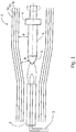
- Die Erfindung soll nachfolgend anhand eines Ausführungsbeispiels näher erläutert werden. Zur Verdeutlichung dienen die
Figuren 1 und2 . Es werden für gleiche oder gleichwirkende Teile die selben Bezugszeichen verwendet. Es zeigt: - Fig. 1
- einen grundsätzlichen Muffelaufbau,
- Fig. 2
- eine Darstellung einer Ofenraumverlängerung.
- Das vorgeschlagene Flammenhydrolyse-Verfahren wird in einem Muffelofen ausgeführt. Dieser weist die für derartige Öfen an sich bekannte Gestaltung auf. Er besteht aus einer röhren- oder tunnelartigen Muffel 1, in welcher der Abscheidevorgang stattfindet.
- Bevorzugt wird für die Muffel auf einen mehrschaligen Wandaufbau aus einem porösen wärmedämmenden Material 1a, insbesondere einem faserigen und/oder keramischen Material, einer Beton- oder Schamotte-Wand 1b und einer inneren Auskleidung 1c aus einem gegenüber hohen Temperaturen hinreichend widerstandsfähigen Material, insbesondere Aluminiumoxid oder Siliziumcarbid, zurückgegriffen.
- Die Muffel 1 weist an ihren Enden jeweils eine Öffnung auf. Eine der beiden Öffnungen dient dem Einführen eines Stempels 4. Die gegenüberliegende Öffnung weist einen dort eingeführten Brenner 2 auf, der mehrflammig ausgebildet sein kann. Der Brenner 2 ist mit einer Zuleitung 3 für ein siliziumhaltiges Reaktionsmittel ausgestattet, das in gasförmiger Form in den Brennbereich geführt und dort zu Siliziumoxiden SiOx oxidiert wird. Die dabei gebildeten SiOx-Partikel werden im Flammenstrom in Richtung des Stempels 4 getrieben und lagern sich auf dem Stempel ab. Der Stempel 4 ist drehbar gelagert, sodass eine gleichmäßige Bedeckung der Stempeloberfläche mit dem Partikelstrom erfolgt. Dadurch bildet sich auf der Oberfläche des Stempels 4 eine wachsende Schicht aus synthetisch erzeugtem Quarzglas in Form eines Fused Silica Ingots (FS-Ingot) 5.
- Die Prozessführung erfolgt nun so, dass der Abstand zwischen dem Flammenbereich des Brenners 2 und der Oberfläche der sich bildenden Quarzglasschicht im Wesentlichen gleich bleibt. Hierzu wird z.B. der Stempel 4 mit einer kontinuierlichen Geschwindigkeit zurückgezogen, sodass sich auf dem Stempel 4 ein Quarzglaszylinder bzw. das FS-Ingot 5 mit einer zunehmenden Länge ausbildet. Es stellt den sich bildenden Stablinsengrundkörper dar, der unmittelbar im Anschluss des Abscheideprozesses entnommen, gekühlt, geprüft und danach direkt als Halbzeug zur Fertigung von einer oder mehrerer Stablinsen verwendet werden kann.
- Das Verfahren gewährleistet eine hohe Temperaturkonstanz über den gesamten Abscheidevorgang und für große Bereiche des Stablinsenkörpers. Wichtig ist hier eine möglichst große Aufschmelzlänge im FS-Ingot, bei der sich Inhomogenitäten in dessen Längsrichtung wirkungsvoll vermeiden lassen. Zweckmäßig haben sich hier Ofenraumtemperaturen im Bereich von 1100 bis 1300 °C erwiesen, wobei die Temperatur über eine Einstellung und Überwachung der Ablufttemperatur geregelt wird. Dabei erweist sich eine Ablufttemperatur von 230 bis 270 °C als zweckmäßig.
- Der Abstand b zwischen der Muffelinnenwand und der Aufschmelzfläche des abgeschiedenen FS-Ingots wird zweckmäßigerweise über eine Lichtschrankenüberwachung konstant gehalten. Als zweckmäßig haben sich hier Abstände von 10 bis 25 mm erwiesen.
- Vorteilhaft ist auch die Einstellung und Vorwahl eines reproduzierbaren Reaktionsraumvolumens zwischen dem sich herausbildenden FS-Ingot und der Muffelinnenseite. Hier kommen jeweils verschiedene Muffelgeometrien zum Einsatz, die einen Abstand a zwischen der Mantelfläche des FS-Ingots und der Muffelinnenwand im Bereich von 40 bis 75 mm gewährleisten.
- Zweckmäßig ist in diesem Zusammenhang eine angepasste und veränderbar ausgeführte Verlängerung 7 des Ofenraumes, die an die eigentliche Muffel 1 seitlich anschließt. Eine derartige Ofenraumverlängerung ist in
Fig. 2 dargestellt. Diese trägt zusätzlich zur Temperaturkonstanz im Muffelraum bei. Die Verlängerung weist z.B. eine Länge L von ca. 50 bis ca. 250 mm auf. - Es hat sich gezeigt, dass mit dem oben genannten Verfahren vor allem Stablinsenkörper mit einem großen Verhältnis zwischen Kantenlänge und Höhe/ Dicke gefertigt werden können. Typische Längen des Stablinsenkörpers liegen bei mindestens 800 mm und können problemlos bis zu 1500 mm und mehr betragen. Damit ist die Kantenlänge L um ein Vielfaches größer als die Höhe H oder Dicke D bei vergleichsweise üblichen Stablinsen.
- Das synthetische Quarzglas des fertigen Stablinsenkörpers ist über dessen gesamte Länge völlig homogen ohne Blasen, Schichtungen, Einschlüsse und Schlieren. Es weist einen hohen Gehalt an OH-Gruppen von mindestens 1000 ppm, insbesondere von 1200 ppm und mehr auf. Der Gehalt an molekularem Wasserstoff H2 liegt oberhalb von 0,8 · 1018 Moleküle/cm3, typischerweise bei 1,2 · 1018 Moleküle/cm3. Der Wert der Spannungsdoppelbrechung ist kleiner als 5 nm/cm und liegt meist unterhalb von 3 nm/cm. In axialer Richtung wird eine hohe Brechzahlhomogenität mit einer Abweichung von 4 · 10-6 und weniger erreicht. Der Glaswerkstoff weist über dessen gesamte Länge ein maximales Transmissionsvermögen für Licht im ultravioletten Spektralbereich, d.h. im Bereich von ca. 193 bis 400 nm. Zugleich werden dadurch unerwünschte Fluoreszenzen unter der Einwirkung von eingestrahltem Laserlicht in der fertigen Stablinse unterdrückt.
- Es lassen sich problemlos aus einem erfindungsgemäßen Quarzglaszylinder (Stablinsengrundkörper) zwei oder mehrere Stablinsen fertigen, die hinsichtlich ihrer Materialeigenschaften praktisch identisch sind, unabhängig davon, aus welchem Abschnitt des ursprünglichen Zylinders die schließlich vorliegende Stablinse herausgeschnitten worden ist.
- Die Erfindung wurde anhand beispielhafter Ausführungsformen erläutert. Im Rahmen fachmännischen Handelns sind weitere Ausführungsformen möglich. Diese ergeben sich ebenso aus den Unteransprüchen.
-
- 1
- Muffel
- 1a
- wärmedämmendes Material
- 1b
- Beton oder Schamotte-Wand
- 1c
- innere Auskleidung
- 2
- Brenner
- 3
- Zuleitung für Reaktionsmittel
- 4
- Stempel
- 5
- FS-Ingot
- 6
- Aufschmelzfläche
- 7
- Ofenraumverlängerung
- a
- Abstand Mantelfläche FS-Ingot zu Muffelinnenwand
- b
- Abstand Aufschmelzfläche zu Muffelinnenwand
- L
- Länge der Ofenraumverlängerung
Claims (6)
- Verfahren zum Herstellen von Stablinsen mit einer Dicke D und einer Höhe H, wobei die Dicke und die Höhe Katheten eines rechtwinkeligen Dreiecks bilden und die sich daraus ergebende Hypothenuse als umhüllender Durchmesser bezeichnet wird mit einem umhüllenden Durchmesser der Stablinsenstirnseite von bis zu 200 mm und einer Kantenlänge von mindestens 800 mm,
gekennzeichnet durch
eine Fertigung des Stablinsengrundkörpers aus einem synthetischen Quarzglasmaterial in Form eines Fused Silica Ingots auf der Basis eines Flammenhydrolyse-Verfahrens mit direktem einstufigen Abscheideprozess von SiOx-Partikeln aus einem Flammenstrom auf einen rotierenden und bezogen auf den Flammenstrom verschiebbaren Stempel in einem direkten Schmelzverfahren, mit den Verfahrensschritten- Zurückziehen eines Stempels mit einer kontinuierlichen Geschwindigkeit, wobei sich auf dem Stempel ein Quarzglaszylinder als Stablinsengrundkörper mit einer zunehmenden Länge ausbildet,- wobei der Abscheideprozess bei einer Ofenraumtemperatur im Bereich von 1100 bis 1300 °C ausgeführt wird und ein Abstand (b) zwischen einer Muffelinnenwand und einer Aufschmelzfläche des abgeschiedenen FS-Ingots in einem Abstandsbereich von 10 bis 25 mm konstant gehalten wird,- wobei eine Vorwahl und Einstellung eines reproduzierbaren Reaktionsraumvolumens zwischen dem sich herausbildenden FS-Ingot und der Muffelinnenseite über eine Muffelgeometrie erfolgt, bei der ein Abstand (a) zwischen der Mantelfläche des FS-Ingots und der Muffelinnenwand im Bereich von 40 bis 75 mm gewährleistet ist,- Unmittelbar im Anschluss des Abscheideprozesses Entnehmen, Kühlen und Prüfen des Stablinsengrundkörpers, wobei- der Stablinsengrundkörper direkt als Halbzeug zur Fertigung von einer oder mehrerer Stablinsen verwendet wird. - Verfahren nach Anspruch 1,
dadurch gekennzeichnet, dass
in dem Abscheideprozess eine synthetische Quarzglasmaterialmenge mit einem OH-Anteil von mehr als 1000 ppm und/oder einen H2-Anteil von mehr als 0,8 · 1018 Molekülen/cm3, typischerweise 1,2 · 1018 Moleküle/cm3 abgeschieden wird. - Verfahren nach einem der vorhergehenden Ansprüche,
dadurch gekennzeichnet, dass
in dem Abscheideprozess eine synthetische Quarzglasmaterialmenge mit einem maximalen Transmissionsvermögen für ultraviolette Strahlung im Wellenlängenbereich von 193 bis 400 nm abgeschieden wird. - Verwenden eines Flammenhydrolyse-Verfahrens mit direktem einstufigen Abscheideprozess von SiOx-Partikeln aus einem Flammenstrom auf einen rotierenden und verschiebbaren Stempel zum Fertigen eines zur Herstellung einer Stablinse geeigneten Zylinderkörpers,- wobei der Abscheideprozess bei einer Ofenraumtemperatur im Bereich von 1100 bis 1300 °C ausgeführt wird und ein Abstand (b) zwischen einer Muffelinnenwand und einer Aufschmelzfläche des abgeschiedenen FS-Ingots in einem Abstandsbereich von 10 bis 25 mm konstant gehalten wird,- wobei eine Vorwahl und Einstellung eines reproduzierbaren Reaktionsraumvolumens zwischen dem sich herausbildenden FS-Ingot und der Muffelinnenseite über eine Muffelgeometrie erfolgt, bei der ein Abstand (a) zwischen der Mantelfläche des FS-Ingots und der Muffelinnenwand im Bereich von 40 bis 75 mm gewährleistet.
- Vorrichtung zum Herstellen eines Stablinsengrundkörpers in Zylinderform umfassend einen Muffelofen mit einer mehrschaligen röhren- oder tunnelförmigen Muffel (1), einem auf einer ersten Seite in die Muffel hinein geführten Brenner (2) mit einer Zuleitung (3) für ein siliziumhaltiges Reaktionsmittel und einem, auf einer zweiten Seite der Muffel, dem Brenner gegenüberliegenden Seite verschiebbaren Stempel (4),
dadurch gekennzeichnet, dass
die Muffel eine Muffelgeometrie aufweist, bei der ein Abstand (a) zwischen der Mantelfläche des sich bildenden Stablinsengrundkörpers (5) und der Innenwand der Muffel im Bereich von 40 bis 75 mm und ein Abstand (b) zwischen der Muffel und der Aufschmelzfläche (6) des Grundkörpers (5) von 10 bis 25 mm gewährleistet ist und mit der Muffel eine abluftgeregelte Ofenraumtemperatur von 1100 bis 1300 °C erreichbar ist. - Vorrichtung nach Anspruch 5,
dadurch gekennzeichnet, dass
die Muffel eine temperaturstabilisierende Ofenraumverlängerung (7) mit einer Länge von mindestens 50 mm aufweist.
Applications Claiming Priority (2)
| Application Number | Priority Date | Filing Date | Title |
|---|---|---|---|
| DE102011122184 | 2011-12-23 | ||
| DE102012000418A DE102012000418A1 (de) | 2011-12-23 | 2012-01-12 | Verfahren zum Herstellen von Stablinsen und Vorrichtung hierfür |
Publications (2)
| Publication Number | Publication Date |
|---|---|
| EP2607325A1 EP2607325A1 (de) | 2013-06-26 |
| EP2607325B1 true EP2607325B1 (de) | 2019-08-21 |
Family
ID=47290796
Family Applications (1)
| Application Number | Title | Priority Date | Filing Date |
|---|---|---|---|
| EP12195986.0A Active EP2607325B1 (de) | 2011-12-23 | 2012-12-07 | Verfahren zum Herstellen von Stablinsen und Vorrichtung hierfür |
Country Status (6)
| Country | Link |
|---|---|
| US (2) | US20130160496A1 (de) |
| EP (1) | EP2607325B1 (de) |
| JP (1) | JP5763612B2 (de) |
| KR (1) | KR20130073846A (de) |
| DE (1) | DE102012000418A1 (de) |
| IL (1) | IL223764A (de) |
Families Citing this family (2)
| Publication number | Priority date | Publication date | Assignee | Title |
|---|---|---|---|---|
| JP5848320B2 (ja) * | 2013-12-20 | 2016-01-27 | デクセリアルズ株式会社 | 円筒基材、原盤、及び原盤の製造方法 |
| CN111320360A (zh) * | 2020-03-04 | 2020-06-23 | 广州精点科技有限公司 | 一种用于光学镜片热压成型的自动化上下料的装置 |
Family Cites Families (24)
| Publication number | Priority date | Publication date | Assignee | Title |
|---|---|---|---|---|
| CA1188895A (en) | 1980-09-11 | 1985-06-18 | Shoichi Suto | Fabrication methods of doped silica glass and optical fiber preform by using the doped silica glass |
| JPS57100934A (en) * | 1980-12-12 | 1982-06-23 | Nippon Telegr & Teleph Corp <Ntt> | Manufacturing of optical fiber preform |
| JPS5978947A (ja) * | 1982-10-22 | 1984-05-08 | Furukawa Electric Co Ltd:The | 光学系ガラスの堆積方法 |
| JPS62216935A (ja) * | 1986-03-19 | 1987-09-24 | Furukawa Electric Co Ltd:The | 石英系ガラス母材の製造方法 |
| US5086352A (en) * | 1989-06-09 | 1992-02-04 | Shin-Etsu Quartz Products Co., Ltd. | Optical members and blanks or synthetic silica glass and method for their production |
| US5707908A (en) * | 1995-01-06 | 1998-01-13 | Nikon Corporation | Silica glass |
| US6518210B1 (en) * | 1995-01-06 | 2003-02-11 | Nikon Corporation | Exposure apparatus including silica glass and method for producing silica glass |
| US5616159A (en) | 1995-04-14 | 1997-04-01 | Corning Incorporated | Method of forming high purity fused silica having high resistance to optical damage |
| JPH09278453A (ja) * | 1996-04-16 | 1997-10-28 | Sumitomo Electric Ind Ltd | ロッドレンズ用素材の製造方法 |
| ATE201390T1 (de) * | 1997-03-07 | 2001-06-15 | Schott Ml Gmbh | Vorform aus synthetischem kieselglas und vorrichtung zu ihrer herstellung |
| JPH1129331A (ja) * | 1997-05-14 | 1999-02-02 | Nikon Corp | 合成石英ガラス光学部材の製造方法および光学部材 |
| TW440548B (en) * | 1997-05-14 | 2001-06-16 | Nippon Kogaku Kk | Synthetic silica glass optical member and method of manufacturing the same |
| JP2001010833A (ja) * | 1999-06-21 | 2001-01-16 | Nikon Corp | 石英ガラス部材 |
| DE19960211B4 (de) * | 1999-12-14 | 2005-08-04 | Schott Ag | Vorrichtung zum Herstellen eines Glasstranges |
| JP3715163B2 (ja) * | 1999-12-24 | 2005-11-09 | 東芝セラミックス株式会社 | 高出力ArFエキシマレーザー用合成石英ガラス部材およびその製造方法 |
| JP2004151682A (ja) * | 2002-09-04 | 2004-05-27 | Nippon Sheet Glass Co Ltd | 屈折率分布型ロッドレンズ被覆用ガラス、屈折率分布型ロッドレンズおよびその製造方法 |
| US20070049482A1 (en) * | 2005-08-11 | 2007-03-01 | Shin-Etsu Chemical Co., Ltd. | Synthetic quartz glass substrate for excimer lasers and making method |
| DE102005043289B3 (de) | 2005-09-09 | 2006-09-14 | Heraeus Tenevo Gmbh | Verfahren zur Herstellung eines Halbzeugs für ein optisches Bauteil hoher Homogenität, zur Durchführung des Verfahrens geeigneter Rohling sowie Verwendung des Rohlings und des Halbzeugs |
| JP4569779B2 (ja) * | 2006-09-07 | 2010-10-27 | 信越化学工業株式会社 | 合成石英ガラスインゴット及び合成石英ガラス部材の製造方法 |
| DE102006061931B3 (de) * | 2006-12-21 | 2008-04-17 | Institut für Physikalische Hochtechnologie e.V. | Verfahren zur Herstellung von Quarzglas mit geringem OH-Gehalt |
| JP5270862B2 (ja) * | 2007-05-15 | 2013-08-21 | 信越石英株式会社 | 銅含有シリカガラス及びその製造方法、並びにそれを用いたキセノンフラッシュランプ |
| DE102008063299B4 (de) * | 2008-12-29 | 2012-12-06 | J-Fiber Gmbh | Verfahren zur Herstellung eines kompakten synthetischen Quarzglases, ein Muffelofen zur Durchführung des Verfahrens, sowie das damit erhaltene Quarzglas |
| JP5796492B2 (ja) * | 2009-10-30 | 2015-10-21 | 旭硝子株式会社 | 深紫外線用光学部材およびその製造方法 |
| JP5304720B2 (ja) * | 2010-04-27 | 2013-10-02 | 信越化学工業株式会社 | 合成石英ガラスインゴット及び合成石英ガラス部材の製造方法 |
-
2012
- 2012-01-12 DE DE102012000418A patent/DE102012000418A1/de not_active Ceased
- 2012-12-07 EP EP12195986.0A patent/EP2607325B1/de active Active
- 2012-12-19 JP JP2012276523A patent/JP5763612B2/ja active Active
- 2012-12-20 US US13/721,609 patent/US20130160496A1/en not_active Abandoned
- 2012-12-20 IL IL223764A patent/IL223764A/en not_active IP Right Cessation
- 2012-12-21 KR KR1020120150758A patent/KR20130073846A/ko not_active Ceased
-
2015
- 2015-11-11 US US14/938,069 patent/US9738556B2/en active Active
Non-Patent Citations (1)
| Title |
|---|
| None * |
Also Published As
| Publication number | Publication date |
|---|---|
| US20130160496A1 (en) | 2013-06-27 |
| KR20130073846A (ko) | 2013-07-03 |
| IL223764A (en) | 2017-05-29 |
| US9738556B2 (en) | 2017-08-22 |
| EP2607325A1 (de) | 2013-06-26 |
| JP2013133277A (ja) | 2013-07-08 |
| JP5763612B2 (ja) | 2015-08-12 |
| US20160060155A1 (en) | 2016-03-03 |
| DE102012000418A1 (de) | 2013-06-27 |
Similar Documents
| Publication | Publication Date | Title |
|---|---|---|
| EP3766844B1 (de) | Verfahren zur herstellung einer hohlkernfaser und zur herstellung einer vorform für eine hohlkernfaser | |
| EP3766848B1 (de) | Verfahren zur herstellung einer hohlkernfaser und zur herstellung einer vorform für eine hohlkernfaser | |
| DE112013007710B4 (de) | Verfahren zum Formen von Komponenten aus opakem Quarzglas | |
| EP3766849B1 (de) | Verfahren zur herstellung einer hohlkernfaser und zur herstellung einer vorform für eine hohlkernfaser | |
| DE102006056613A1 (de) | Glasgegenstände und Verfahren zu ihrer Herstellung | |
| DE102004054392A1 (de) | Verfahren zum Verbinden von Bauteilen aus hochkieselsäurehaltigem Werkstoff, sowie aus derartigen Bauteilen zusammengefügter Bauteil-Verbund | |
| EP1791796B1 (de) | Verfahren zum verbinden von bauteilen aus hochkieselsäurehaltigem werkstoff unter einsatz eines fügemittels, sowie nach dem verfahren erhaltener bauteil-verbund | |
| EP3766851B1 (de) | Verfahren zur herstellung einer hohlkernfaser und zur herstellung einer vorform für eine hohlkernfaser | |
| EP2714603B1 (de) | Verfahren zur herstellung eines halbzeugs zur fertigung einer biegeoptimierten lichtleitfaser | |
| EP3766840B1 (de) | Verfahren zur herstellung einer hohlkernfaser und zur herstellung einer vorform für eine hohlkernfaser | |
| DE112012005570T5 (de) | Formvorrichtung und Formverfahren für Glasgehäuse | |
| EP2141131A2 (de) | Verfahren zur Herstellung eines Quarzglastiegels | |
| DE102013104589A1 (de) | Verfahren zur Einstelllung einer Verwölbung einer chemisch vorgespannten Glasscheibe und verfahrensgemäß herstellbare Glasscheibe | |
| EP0964832B1 (de) | Vorform aus synthetischem kieselglas und vorrichtung zu ihrer herstellung | |
| DE102010036999B4 (de) | Verfahren zur Herstellung eines gebogenen Glas- oder Glaskeramik-Formteils | |
| DE102013102989A1 (de) | Verfahren und Vorrichtung zum Ziehen eines Stabes, eines Rohres oder einer Platte aus Quarzglas | |
| EP2607325A1 (de) | Verfahren zum Herstellen von Stablinsen und Vorrichtung hierfür | |
| WO2011082920A1 (de) | Quarzglasbauteil mit opaker innenzone sowie verfahren zur herstellung desselben | |
| DE102008056084B4 (de) | Zylinderförmiges Halbzeug zur Herstellung einer optischen Faser sowie Verfahren für die Herstellung der Faser oder einer Vorform dafür | |
| DE19527794C2 (de) | Verfahren und Vorrichtung zur Herstellung optischer Elemente für die Kapillaroptik | |
| DE102006024831B4 (de) | Verfahren zur Herstellung eines Halbzeugs aus synthetischem Quarzglas | |
| DE102004014345B4 (de) | Verfahren zur Herstellung eines optischen Bauteils | |
| DE102012112449A1 (de) | Verfahren zur Herstellung eines Zylinders aus Quarzglas | |
| DE60209293T2 (de) | Verfahren und Ofen zur Herstellung eines optischen Quarzglases | |
| DE102013202589A1 (de) | Verfahren zum Fertigen eines Lichtwellenleiters mit einem Kern aus einem dotierten oder undotierten Kernmaterial in einer Vieleckform |
Legal Events
| Date | Code | Title | Description |
|---|---|---|---|
| AK | Designated contracting states |
Kind code of ref document: A1 Designated state(s): AL AT BE BG CH CY CZ DE DK EE ES FI FR GB GR HR HU IE IS IT LI LT LU LV MC MK MT NL NO PL PT RO RS SE SI SK SM TR |
|
| AX | Request for extension of the european patent |
Extension state: BA ME |
|
| PUAI | Public reference made under article 153(3) epc to a published international application that has entered the european phase |
Free format text: ORIGINAL CODE: 0009012 |
|
| 17P | Request for examination filed |
Effective date: 20131030 |
|
| RBV | Designated contracting states (corrected) |
Designated state(s): AL AT BE BG CH CY CZ DE DK EE ES FI FR GB GR HR HU IE IS IT LI LT LU LV MC MK MT NL NO PL PT RO RS SE SI SK SM TR |
|
| STAA | Information on the status of an ep patent application or granted ep patent |
Free format text: STATUS: EXAMINATION IS IN PROGRESS |
|
| 17Q | First examination report despatched |
Effective date: 20170208 |
|
| GRAP | Despatch of communication of intention to grant a patent |
Free format text: ORIGINAL CODE: EPIDOSNIGR1 |
|
| STAA | Information on the status of an ep patent application or granted ep patent |
Free format text: STATUS: GRANT OF PATENT IS INTENDED |
|
| INTG | Intention to grant announced |
Effective date: 20190308 |
|
| GRAS | Grant fee paid |
Free format text: ORIGINAL CODE: EPIDOSNIGR3 |
|
| GRAA | (expected) grant |
Free format text: ORIGINAL CODE: 0009210 |
|
| STAA | Information on the status of an ep patent application or granted ep patent |
Free format text: STATUS: THE PATENT HAS BEEN GRANTED |
|
| AK | Designated contracting states |
Kind code of ref document: B1 Designated state(s): AL AT BE BG CH CY CZ DE DK EE ES FI FR GB GR HR HU IE IS IT LI LT LU LV MC MK MT NL NO PL PT RO RS SE SI SK SM TR |
|
| REG | Reference to a national code |
Ref country code: GB Ref legal event code: FG4D Free format text: NOT ENGLISH |
|
| REG | Reference to a national code |
Ref country code: CH Ref legal event code: EP |
|
| REG | Reference to a national code |
Ref country code: DE Ref legal event code: R096 Ref document number: 502012015178 Country of ref document: DE |
|
| REG | Reference to a national code |
Ref country code: AT Ref legal event code: REF Ref document number: 1169552 Country of ref document: AT Kind code of ref document: T Effective date: 20190915 |
|
| REG | Reference to a national code |
Ref country code: IE Ref legal event code: FG4D Free format text: LANGUAGE OF EP DOCUMENT: GERMAN |
|
| REG | Reference to a national code |
Ref country code: LT Ref legal event code: MG4D |
|
| REG | Reference to a national code |
Ref country code: NL Ref legal event code: MP Effective date: 20190821 |
|
| PG25 | Lapsed in a contracting state [announced via postgrant information from national office to epo] |
Ref country code: PT Free format text: LAPSE BECAUSE OF FAILURE TO SUBMIT A TRANSLATION OF THE DESCRIPTION OR TO PAY THE FEE WITHIN THE PRESCRIBED TIME-LIMIT Effective date: 20191223 Ref country code: NO Free format text: LAPSE BECAUSE OF FAILURE TO SUBMIT A TRANSLATION OF THE DESCRIPTION OR TO PAY THE FEE WITHIN THE PRESCRIBED TIME-LIMIT Effective date: 20191121 Ref country code: BG Free format text: LAPSE BECAUSE OF FAILURE TO SUBMIT A TRANSLATION OF THE DESCRIPTION OR TO PAY THE FEE WITHIN THE PRESCRIBED TIME-LIMIT Effective date: 20191121 Ref country code: SE Free format text: LAPSE BECAUSE OF FAILURE TO SUBMIT A TRANSLATION OF THE DESCRIPTION OR TO PAY THE FEE WITHIN THE PRESCRIBED TIME-LIMIT Effective date: 20190821 Ref country code: FI Free format text: LAPSE BECAUSE OF FAILURE TO SUBMIT A TRANSLATION OF THE DESCRIPTION OR TO PAY THE FEE WITHIN THE PRESCRIBED TIME-LIMIT Effective date: 20190821 Ref country code: HR Free format text: LAPSE BECAUSE OF FAILURE TO SUBMIT A TRANSLATION OF THE DESCRIPTION OR TO PAY THE FEE WITHIN THE PRESCRIBED TIME-LIMIT Effective date: 20190821 Ref country code: NL Free format text: LAPSE BECAUSE OF FAILURE TO SUBMIT A TRANSLATION OF THE DESCRIPTION OR TO PAY THE FEE WITHIN THE PRESCRIBED TIME-LIMIT Effective date: 20190821 Ref country code: LT Free format text: LAPSE BECAUSE OF FAILURE TO SUBMIT A TRANSLATION OF THE DESCRIPTION OR TO PAY THE FEE WITHIN THE PRESCRIBED TIME-LIMIT Effective date: 20190821 |
|
| PG25 | Lapsed in a contracting state [announced via postgrant information from national office to epo] |
Ref country code: AL Free format text: LAPSE BECAUSE OF FAILURE TO SUBMIT A TRANSLATION OF THE DESCRIPTION OR TO PAY THE FEE WITHIN THE PRESCRIBED TIME-LIMIT Effective date: 20190821 Ref country code: ES Free format text: LAPSE BECAUSE OF FAILURE TO SUBMIT A TRANSLATION OF THE DESCRIPTION OR TO PAY THE FEE WITHIN THE PRESCRIBED TIME-LIMIT Effective date: 20190821 Ref country code: GR Free format text: LAPSE BECAUSE OF FAILURE TO SUBMIT A TRANSLATION OF THE DESCRIPTION OR TO PAY THE FEE WITHIN THE PRESCRIBED TIME-LIMIT Effective date: 20191122 Ref country code: RS Free format text: LAPSE BECAUSE OF FAILURE TO SUBMIT A TRANSLATION OF THE DESCRIPTION OR TO PAY THE FEE WITHIN THE PRESCRIBED TIME-LIMIT Effective date: 20190821 Ref country code: LV Free format text: LAPSE BECAUSE OF FAILURE TO SUBMIT A TRANSLATION OF THE DESCRIPTION OR TO PAY THE FEE WITHIN THE PRESCRIBED TIME-LIMIT Effective date: 20190821 Ref country code: IS Free format text: LAPSE BECAUSE OF FAILURE TO SUBMIT A TRANSLATION OF THE DESCRIPTION OR TO PAY THE FEE WITHIN THE PRESCRIBED TIME-LIMIT Effective date: 20191221 |
|
| PG25 | Lapsed in a contracting state [announced via postgrant information from national office to epo] |
Ref country code: TR Free format text: LAPSE BECAUSE OF FAILURE TO SUBMIT A TRANSLATION OF THE DESCRIPTION OR TO PAY THE FEE WITHIN THE PRESCRIBED TIME-LIMIT Effective date: 20190821 |
|
| PG25 | Lapsed in a contracting state [announced via postgrant information from national office to epo] |
Ref country code: PL Free format text: LAPSE BECAUSE OF FAILURE TO SUBMIT A TRANSLATION OF THE DESCRIPTION OR TO PAY THE FEE WITHIN THE PRESCRIBED TIME-LIMIT Effective date: 20190821 Ref country code: RO Free format text: LAPSE BECAUSE OF FAILURE TO SUBMIT A TRANSLATION OF THE DESCRIPTION OR TO PAY THE FEE WITHIN THE PRESCRIBED TIME-LIMIT Effective date: 20190821 Ref country code: IT Free format text: LAPSE BECAUSE OF FAILURE TO SUBMIT A TRANSLATION OF THE DESCRIPTION OR TO PAY THE FEE WITHIN THE PRESCRIBED TIME-LIMIT Effective date: 20190821 Ref country code: DK Free format text: LAPSE BECAUSE OF FAILURE TO SUBMIT A TRANSLATION OF THE DESCRIPTION OR TO PAY THE FEE WITHIN THE PRESCRIBED TIME-LIMIT Effective date: 20190821 Ref country code: EE Free format text: LAPSE BECAUSE OF FAILURE TO SUBMIT A TRANSLATION OF THE DESCRIPTION OR TO PAY THE FEE WITHIN THE PRESCRIBED TIME-LIMIT Effective date: 20190821 |
|
| PG25 | Lapsed in a contracting state [announced via postgrant information from national office to epo] |
Ref country code: IS Free format text: LAPSE BECAUSE OF FAILURE TO SUBMIT A TRANSLATION OF THE DESCRIPTION OR TO PAY THE FEE WITHIN THE PRESCRIBED TIME-LIMIT Effective date: 20200224 Ref country code: CZ Free format text: LAPSE BECAUSE OF FAILURE TO SUBMIT A TRANSLATION OF THE DESCRIPTION OR TO PAY THE FEE WITHIN THE PRESCRIBED TIME-LIMIT Effective date: 20190821 Ref country code: SM Free format text: LAPSE BECAUSE OF FAILURE TO SUBMIT A TRANSLATION OF THE DESCRIPTION OR TO PAY THE FEE WITHIN THE PRESCRIBED TIME-LIMIT Effective date: 20190821 Ref country code: SK Free format text: LAPSE BECAUSE OF FAILURE TO SUBMIT A TRANSLATION OF THE DESCRIPTION OR TO PAY THE FEE WITHIN THE PRESCRIBED TIME-LIMIT Effective date: 20190821 |
|
| REG | Reference to a national code |
Ref country code: DE Ref legal event code: R097 Ref document number: 502012015178 Country of ref document: DE |
|
| PLBE | No opposition filed within time limit |
Free format text: ORIGINAL CODE: 0009261 |
|
| STAA | Information on the status of an ep patent application or granted ep patent |
Free format text: STATUS: NO OPPOSITION FILED WITHIN TIME LIMIT |
|
| PG2D | Information on lapse in contracting state deleted |
Ref country code: IS |
|
| 26N | No opposition filed |
Effective date: 20200603 |
|
| REG | Reference to a national code |
Ref country code: BE Ref legal event code: MM Effective date: 20191231 |
|
| PG25 | Lapsed in a contracting state [announced via postgrant information from national office to epo] |
Ref country code: SI Free format text: LAPSE BECAUSE OF FAILURE TO SUBMIT A TRANSLATION OF THE DESCRIPTION OR TO PAY THE FEE WITHIN THE PRESCRIBED TIME-LIMIT Effective date: 20190821 Ref country code: MC Free format text: LAPSE BECAUSE OF FAILURE TO SUBMIT A TRANSLATION OF THE DESCRIPTION OR TO PAY THE FEE WITHIN THE PRESCRIBED TIME-LIMIT Effective date: 20190821 |
|
| GBPC | Gb: european patent ceased through non-payment of renewal fee |
Effective date: 20191207 |
|
| PG25 | Lapsed in a contracting state [announced via postgrant information from national office to epo] |
Ref country code: GB Free format text: LAPSE BECAUSE OF NON-PAYMENT OF DUE FEES Effective date: 20191207 Ref country code: IE Free format text: LAPSE BECAUSE OF NON-PAYMENT OF DUE FEES Effective date: 20191207 Ref country code: LU Free format text: LAPSE BECAUSE OF NON-PAYMENT OF DUE FEES Effective date: 20191207 |
|
| PG25 | Lapsed in a contracting state [announced via postgrant information from national office to epo] |
Ref country code: BE Free format text: LAPSE BECAUSE OF NON-PAYMENT OF DUE FEES Effective date: 20191231 |
|
| REG | Reference to a national code |
Ref country code: AT Ref legal event code: MM01 Ref document number: 1169552 Country of ref document: AT Kind code of ref document: T Effective date: 20191207 |
|
| PG25 | Lapsed in a contracting state [announced via postgrant information from national office to epo] |
Ref country code: CY Free format text: LAPSE BECAUSE OF FAILURE TO SUBMIT A TRANSLATION OF THE DESCRIPTION OR TO PAY THE FEE WITHIN THE PRESCRIBED TIME-LIMIT Effective date: 20190821 Ref country code: AT Free format text: LAPSE BECAUSE OF NON-PAYMENT OF DUE FEES Effective date: 20191207 |
|
| PG25 | Lapsed in a contracting state [announced via postgrant information from national office to epo] |
Ref country code: MT Free format text: LAPSE BECAUSE OF FAILURE TO SUBMIT A TRANSLATION OF THE DESCRIPTION OR TO PAY THE FEE WITHIN THE PRESCRIBED TIME-LIMIT Effective date: 20190821 Ref country code: HU Free format text: LAPSE BECAUSE OF FAILURE TO SUBMIT A TRANSLATION OF THE DESCRIPTION OR TO PAY THE FEE WITHIN THE PRESCRIBED TIME-LIMIT; INVALID AB INITIO Effective date: 20121207 |
|
| PG25 | Lapsed in a contracting state [announced via postgrant information from national office to epo] |
Ref country code: MK Free format text: LAPSE BECAUSE OF FAILURE TO SUBMIT A TRANSLATION OF THE DESCRIPTION OR TO PAY THE FEE WITHIN THE PRESCRIBED TIME-LIMIT Effective date: 20190821 |
|
| REG | Reference to a national code |
Ref country code: DE Ref legal event code: R082 Ref document number: 502012015178 Country of ref document: DE Representative=s name: EISENFUEHR SPEISER PATENTANWAELTE RECHTSANWAEL, DE |
|
| PGFP | Annual fee paid to national office [announced via postgrant information from national office to epo] |
Ref country code: FR Payment date: 20231219 Year of fee payment: 12 |
|
| PGFP | Annual fee paid to national office [announced via postgrant information from national office to epo] |
Ref country code: CH Payment date: 20240110 Year of fee payment: 12 |
|
| REG | Reference to a national code |
Ref country code: CH Ref legal event code: PL |
|
| PG25 | Lapsed in a contracting state [announced via postgrant information from national office to epo] |
Ref country code: FR Free format text: LAPSE BECAUSE OF NON-PAYMENT OF DUE FEES Effective date: 20241231 |
|
| PG25 | Lapsed in a contracting state [announced via postgrant information from national office to epo] |
Ref country code: CH Free format text: LAPSE BECAUSE OF NON-PAYMENT OF DUE FEES Effective date: 20241231 |
|
| PGFP | Annual fee paid to national office [announced via postgrant information from national office to epo] |
Ref country code: DE Payment date: 20260119 Year of fee payment: 14 |
|
| REG | Reference to a national code |
Ref country code: DE Ref legal event code: R082 Ref document number: 502012015178 Country of ref document: DE Representative=s name: EISENFUEHR SPEISER PATENTANWAELTE RECHTSANWAEL, DE |