EP2607304B1 - Verfahren und Vorrichtung zur Entgasung von flüssigem Schwefel - Google Patents
Verfahren und Vorrichtung zur Entgasung von flüssigem Schwefel Download PDFInfo
- Publication number
- EP2607304B1 EP2607304B1 EP11290609.4A EP11290609A EP2607304B1 EP 2607304 B1 EP2607304 B1 EP 2607304B1 EP 11290609 A EP11290609 A EP 11290609A EP 2607304 B1 EP2607304 B1 EP 2607304B1
- Authority
- EP
- European Patent Office
- Prior art keywords
- gas
- sulfur
- chamber
- area
- liquid
- Prior art date
- Legal status (The legal status is an assumption and is not a legal conclusion. Google has not performed a legal analysis and makes no representation as to the accuracy of the status listed.)
- Not-in-force
Links
- NINIDFKCEFEMDL-UHFFFAOYSA-N Sulfur Chemical compound [S] NINIDFKCEFEMDL-UHFFFAOYSA-N 0.000 title claims description 209
- 239000007788 liquid Substances 0.000 title claims description 110
- 238000000034 method Methods 0.000 title claims description 49
- 239000005864 Sulphur Substances 0.000 title claims 16
- 239000007789 gas Substances 0.000 claims description 157
- 238000007872 degassing Methods 0.000 claims description 56
- RWSOTUBLDIXVET-UHFFFAOYSA-N Dihydrogen sulfide Chemical compound S RWSOTUBLDIXVET-UHFFFAOYSA-N 0.000 claims description 33
- 239000011261 inert gas Substances 0.000 claims description 13
- 238000005192 partition Methods 0.000 claims description 13
- QVGXLLKOCUKJST-UHFFFAOYSA-N atomic oxygen Chemical compound [O] QVGXLLKOCUKJST-UHFFFAOYSA-N 0.000 claims description 9
- 239000001301 oxygen Substances 0.000 claims description 9
- 229910052760 oxygen Inorganic materials 0.000 claims description 9
- 238000005507 spraying Methods 0.000 claims description 7
- 239000007921 spray Substances 0.000 claims description 3
- 229910052717 sulfur Inorganic materials 0.000 description 193
- 239000011593 sulfur Substances 0.000 description 187
- 230000008569 process Effects 0.000 description 26
- 239000012071 phase Substances 0.000 description 22
- 229910000037 hydrogen sulfide Inorganic materials 0.000 description 18
- 238000002347 injection Methods 0.000 description 15
- 239000007924 injection Substances 0.000 description 15
- 230000005587 bubbling Effects 0.000 description 13
- RAHZWNYVWXNFOC-UHFFFAOYSA-N Sulphur dioxide Chemical compound O=S=O RAHZWNYVWXNFOC-UHFFFAOYSA-N 0.000 description 12
- 238000006243 chemical reaction Methods 0.000 description 10
- 239000007791 liquid phase Substances 0.000 description 9
- 238000007254 oxidation reaction Methods 0.000 description 9
- QGZKDVFQNNGYKY-UHFFFAOYSA-N Ammonia Chemical compound N QGZKDVFQNNGYKY-UHFFFAOYSA-N 0.000 description 8
- 239000003054 catalyst Substances 0.000 description 8
- 229910052739 hydrogen Inorganic materials 0.000 description 8
- 230000015572 biosynthetic process Effects 0.000 description 7
- 238000010924 continuous production Methods 0.000 description 7
- 239000000203 mixture Substances 0.000 description 7
- 238000010926 purge Methods 0.000 description 7
- 238000004544 sputter deposition Methods 0.000 description 7
- 230000032258 transport Effects 0.000 description 7
- 229930195733 hydrocarbon Natural products 0.000 description 6
- 150000002430 hydrocarbons Chemical class 0.000 description 6
- 238000004519 manufacturing process Methods 0.000 description 6
- 239000000047 product Substances 0.000 description 6
- 239000000126 substance Substances 0.000 description 6
- 238000000889 atomisation Methods 0.000 description 5
- 230000015556 catabolic process Effects 0.000 description 5
- 238000006731 degradation reaction Methods 0.000 description 5
- 238000009792 diffusion process Methods 0.000 description 5
- 239000007792 gaseous phase Substances 0.000 description 5
- 230000003647 oxidation Effects 0.000 description 5
- 238000005086 pumping Methods 0.000 description 5
- 150000003464 sulfur compounds Chemical class 0.000 description 5
- 239000002253 acid Substances 0.000 description 4
- 229910021529 ammonia Inorganic materials 0.000 description 4
- 238000010923 batch production Methods 0.000 description 4
- 238000002485 combustion reaction Methods 0.000 description 4
- 238000001816 cooling Methods 0.000 description 4
- 239000012535 impurity Substances 0.000 description 4
- 238000003860 storage Methods 0.000 description 4
- 230000007704 transition Effects 0.000 description 4
- IJGRMHOSHXDMSA-UHFFFAOYSA-N Atomic nitrogen Chemical compound N#N IJGRMHOSHXDMSA-UHFFFAOYSA-N 0.000 description 3
- UFHFLCQGNIYNRP-UHFFFAOYSA-N Hydrogen Chemical compound [H][H] UFHFLCQGNIYNRP-UHFFFAOYSA-N 0.000 description 3
- 230000008901 benefit Effects 0.000 description 3
- 239000006185 dispersion Substances 0.000 description 3
- 238000000605 extraction Methods 0.000 description 3
- 230000002349 favourable effect Effects 0.000 description 3
- 239000001257 hydrogen Substances 0.000 description 3
- 125000004435 hydrogen atom Chemical group [H]* 0.000 description 3
- 239000007787 solid Substances 0.000 description 3
- SMWDFEZZVXVKRB-UHFFFAOYSA-N Quinoline Chemical compound N1=CC=CC2=CC=CC=C21 SMWDFEZZVXVKRB-UHFFFAOYSA-N 0.000 description 2
- 229910000831 Steel Inorganic materials 0.000 description 2
- 150000007513 acids Chemical class 0.000 description 2
- PNEYBMLMFCGWSK-UHFFFAOYSA-N aluminium oxide Inorganic materials [O-2].[O-2].[O-2].[Al+3].[Al+3] PNEYBMLMFCGWSK-UHFFFAOYSA-N 0.000 description 2
- 150000001875 compounds Chemical class 0.000 description 2
- 238000000354 decomposition reaction Methods 0.000 description 2
- 238000011049 filling Methods 0.000 description 2
- 238000010438 heat treatment Methods 0.000 description 2
- VNWKTOKETHGBQD-UHFFFAOYSA-N methane Chemical compound C VNWKTOKETHGBQD-UHFFFAOYSA-N 0.000 description 2
- 238000002156 mixing Methods 0.000 description 2
- 229910017464 nitrogen compound Inorganic materials 0.000 description 2
- 239000003208 petroleum Substances 0.000 description 2
- 238000000926 separation method Methods 0.000 description 2
- 239000010959 steel Substances 0.000 description 2
- 150000003463 sulfur Chemical class 0.000 description 2
- 229910018072 Al 2 O 3 Inorganic materials 0.000 description 1
- 239000004215 Carbon black (E152) Substances 0.000 description 1
- 238000009625 Frasch process Methods 0.000 description 1
- GVGLGOZIDCSQPN-PVHGPHFFSA-N Heroin Chemical compound O([C@H]1[C@H](C=C[C@H]23)OC(C)=O)C4=C5[C@@]12CCN(C)[C@@H]3CC5=CC=C4OC(C)=O GVGLGOZIDCSQPN-PVHGPHFFSA-N 0.000 description 1
- XSQUKJJJFZCRTK-UHFFFAOYSA-N Urea Chemical compound NC(N)=O XSQUKJJJFZCRTK-UHFFFAOYSA-N 0.000 description 1
- 238000010521 absorption reaction Methods 0.000 description 1
- 230000035508 accumulation Effects 0.000 description 1
- 238000009825 accumulation Methods 0.000 description 1
- 230000009471 action Effects 0.000 description 1
- 150000001412 amines Chemical class 0.000 description 1
- 230000009286 beneficial effect Effects 0.000 description 1
- 208000002352 blister Diseases 0.000 description 1
- 230000009172 bursting Effects 0.000 description 1
- 239000004202 carbamide Substances 0.000 description 1
- 230000003197 catalytic effect Effects 0.000 description 1
- 238000001311 chemical methods and process Methods 0.000 description 1
- 239000003795 chemical substances by application Substances 0.000 description 1
- 239000013065 commercial product Substances 0.000 description 1
- 230000007797 corrosion Effects 0.000 description 1
- 238000005260 corrosion Methods 0.000 description 1
- 230000001186 cumulative effect Effects 0.000 description 1
- 230000001627 detrimental effect Effects 0.000 description 1
- 229910001873 dinitrogen Inorganic materials 0.000 description 1
- 230000000694 effects Effects 0.000 description 1
- 238000005516 engineering process Methods 0.000 description 1
- 230000007613 environmental effect Effects 0.000 description 1
- 239000003344 environmental pollutant Substances 0.000 description 1
- 238000003912 environmental pollution Methods 0.000 description 1
- 238000004880 explosion Methods 0.000 description 1
- 239000002360 explosive Substances 0.000 description 1
- 238000011010 flushing procedure Methods 0.000 description 1
- 229940083124 ganglion-blocking antiadrenergic secondary and tertiary amines Drugs 0.000 description 1
- -1 heterocyclic nitrogen compounds Chemical class 0.000 description 1
- 239000003999 initiator Substances 0.000 description 1
- 230000002045 lasting effect Effects 0.000 description 1
- 231100000518 lethal Toxicity 0.000 description 1
- 230000001665 lethal effect Effects 0.000 description 1
- 238000005065 mining Methods 0.000 description 1
- 239000003595 mist Substances 0.000 description 1
- 150000002780 morpholines Chemical class 0.000 description 1
- 239000003345 natural gas Substances 0.000 description 1
- 239000006199 nebulizer Substances 0.000 description 1
- 229910052757 nitrogen Inorganic materials 0.000 description 1
- 150000002830 nitrogen compounds Chemical class 0.000 description 1
- 238000010943 off-gassing Methods 0.000 description 1
- 230000000704 physical effect Effects 0.000 description 1
- 238000005293 physical law Methods 0.000 description 1
- 231100000719 pollutant Toxicity 0.000 description 1
- 239000003380 propellant Substances 0.000 description 1
- 230000003134 recirculating effect Effects 0.000 description 1
- 238000011084 recovery Methods 0.000 description 1
- 230000001105 regulatory effect Effects 0.000 description 1
- 150000003839 salts Chemical class 0.000 description 1
- 239000002689 soil Substances 0.000 description 1
- 239000011949 solid catalyst Substances 0.000 description 1
- 239000004575 stone Substances 0.000 description 1
- 150000004763 sulfides Chemical class 0.000 description 1
- 231100000331 toxic Toxicity 0.000 description 1
- 230000002588 toxic effect Effects 0.000 description 1
- 231100000419 toxicity Toxicity 0.000 description 1
- 230000001988 toxicity Effects 0.000 description 1
- 238000011144 upstream manufacturing Methods 0.000 description 1
- 238000009423 ventilation Methods 0.000 description 1
- 231100000925 very toxic Toxicity 0.000 description 1
- XLYOFNOQVPJJNP-UHFFFAOYSA-N water Substances O XLYOFNOQVPJJNP-UHFFFAOYSA-N 0.000 description 1
Images
Classifications
-
- C—CHEMISTRY; METALLURGY
- C01—INORGANIC CHEMISTRY
- C01B—NON-METALLIC ELEMENTS; COMPOUNDS THEREOF; METALLOIDS OR COMPOUNDS THEREOF NOT COVERED BY SUBCLASS C01C
- C01B17/00—Sulfur; Compounds thereof
- C01B17/02—Preparation of sulfur; Purification
- C01B17/0232—Purification, e.g. degassing
-
- B—PERFORMING OPERATIONS; TRANSPORTING
- B01—PHYSICAL OR CHEMICAL PROCESSES OR APPARATUS IN GENERAL
- B01D—SEPARATION
- B01D19/00—Degasification of liquids
- B01D19/0005—Degasification of liquids with one or more auxiliary substances
- B01D19/001—Degasification of liquids with one or more auxiliary substances by bubbling steam through the liquid
-
- B—PERFORMING OPERATIONS; TRANSPORTING
- B01—PHYSICAL OR CHEMICAL PROCESSES OR APPARATUS IN GENERAL
- B01D—SEPARATION
- B01D19/00—Degasification of liquids
- B01D19/0042—Degasification of liquids modifying the liquid flow
- B01D19/0047—Atomizing, spraying, trickling
-
- C—CHEMISTRY; METALLURGY
- C01—INORGANIC CHEMISTRY
- C01B—NON-METALLIC ELEMENTS; COMPOUNDS THEREOF; METALLOIDS OR COMPOUNDS THEREOF NOT COVERED BY SUBCLASS C01C
- C01B17/00—Sulfur; Compounds thereof
- C01B17/02—Preparation of sulfur; Purification
Definitions
- the invention relates to a process for degassing liquid sulfur in a container having two contiguous regions, a first region of the liquid sulfur container and a second region of the container being flooded with a gas, and a gas stream being injected into the first region As well as a device for degassing of liquid sulfur using the method according to the invention.
- Liquid sulfur contains gaseous impurities, in particular in the form of H 2 S (hydrogen sulphide), H 2 S x (polyhydric hydrogens), SO 2 (sulfur dioxide) and optionally other gaseous sulfur compounds.
- H 2 S hydrogen sulphide
- H 2 S x polyhydric hydrogens
- SO 2 sulfur dioxide
- H 2 S is a very dangerous compound because it is toxic in the air at a concentration of less than 10 ppm by volume and is lethal at a concentration of some 100 ppm by volume.
- hydrogen sulfide when reaching a concentration of> 3.4 vol .-% hydrogen sulfide in the air form an explosive mixture.
- H 2 S tends to leach out of the liquid sulfur when it is shaken and cooled, which is especially true during handling, storage and transport. The dangerous gas then accumulates in the gaseous phase of the storage and transport containers.
- H 2 S and SO 2 also naturally come from the sulfur. In both cases, non-degassed liquid sulfur thus provides a source of volatile H 2 S and SO 2 emissions in the storage areas and thus not only causes pollutant pollution and environmental pollution but is also a significant security risk.
- the sulfur-related industrial companies have agreed on international regulations that specify the specification of the commercial product, limiting inter alia the total residual hydrogen sulphide content to a maximum of 10 ppm by weight.
- the WO 03/106335 A1 describes, finally, a process for the removal of hydrogen sulfide from liquid sulfur, in which liquid sulfur is introduced from top to bottom in a container and flows through an outlet on the lower side of the device in an outer ring, which is gassed with air.
- Part of the SO 2 is found in the stripping air together with the outgassed H 2 S, which contributes to the sulfur losses of the overall process.
- the described methods for degassing usually require very long degassing times (10 to 20 hours), which leads to an increased SO 2 formation.
- DE 28 42 141 A1 describes a process for degassing liquid sulfur using a catalyst.
- a three-stage column is purged with an ammonia-containing nitrogen gas and the individual stages are charged in cocurrent with sulfur and gas mixture.
- the degassing takes place in several, preferably two chambers, wherein the raw sulfur enters the first chamber, in which it is continuously atomized.
- the liquid sulfur flows into a second chamber.
- the sulfur is kept in motion by a circulation pump, whereby the atomization of the raw sulfur takes place in the gas region of the second chamber. From the second chamber and the degassed sulfur is then withdrawn continuously.
- a first portion of a container of liquid sulfur and a second portion of the container above the liquid phase is flooded with a gas.
- a gas stream is injected, wherein this injection takes place in a preferred manner so that form a plurality of small as possible gas bubbles.
- liquid sulfur is sprayed into the second area flooded with gas, whereby this injection takes place in such a way that the sulfur is atomized as finely as possible.
- the liquid sulfur that is sprayed into the second area comes from the first area and is pumped out of it into the device for spraying. This creates a flow within the liquid sulfur, which ensures a thorough mixing of the system and thus a homogeneous degassing.
- the sulfur degassing with air produces a different amount of SO 2 , with some of the SO 2 remaining in the sulfur in the dissolved state (about 100 ppm by weight).
- Sulfur dioxide is a very toxic, dangerous and polluting product. It causes volatile emissions and accumulations of sulfur dioxide in the vicinity of liquid and solid sulfur plants, which means that these plants must be equipped with suitable ventilation systems and devices to control this emission. This applies in particular to systems for storing granular solid sulfur. The same problem also occurs with means of transport. For these environmental reasons and depending on the use of sulfur further requirements, it may be necessary to minimize the sulfur dioxide in addition to the hydrogen sulfide in the liquid sulfur. By the method according to the invention, in an additional and final degassing step of the sulfur treatment after the H 2 S degassing with air and the SO 2 removed by degassing.
- the removal of the SO 2 by degassing is carried out on the same principle as the degassing with respect to H 2 S.
- sulfur is atomized within a gas-flooded area and the area adjacent to this gas area with liquid sulfur is bubbled with stripping gas.
- Inert gas is used as the stripping gas. It is favorable in this case, a residual gas from a sulfur production plant or a connected residual gas treatment plant (preferably residual gases from a TGT plant type SCOT or LTGT, the purged with amines and completely SO 2 -free residual gases with a H 2 S content from about 100 to 300 ppm by volume)) use.
- the stripping inert gas from the removal of SO 2 after SO 2 removal, may be passed as a gas stream containing the removed SO 2 into the gas-flooded second region of upstream H 2 S removal.
- H 2 S exists in two forms: free physically dissolved H 2 S and H 2 S x (sulfanes or polyhydric hydrocarbons).
- H 2 S x sulfanes or polyhydric hydrocarbons.
- the total content of H 2 S in both forms is between 250 and 500 ppm by weight, based on the total sulfur content.
- the degassing has the purpose of removing the free H 2 S and present in the form of polyhydrocarbons H 2 S.
- the ratio of hydrogen sulfide to polyhydric sulfides within the liquid sulfur varies with temperature, increasing with increasing temperature (20:80 wt% at 130 ° C, 50:50 wt% at 150 ° C).
- the decrease of the hydrogen sulfide partial pressure promotes the degradation of the sulfanes, which is aimed at by the gas stripping of the sulfur. Due to the chemical balance, the degradation kinetics of the polyhydric hydrocarbons becomes the most important parameter limiting the effectiveness of the degassing process. This parameter is particularly critical for the duration of the degassing process.
- Influence on the degradation kinetics of H 2 S x has the chemical nature of the stripping gas used in the first region and of the second region flooding Gas, whereby two different types of gas can be used independently in both areas:
- Inert gases are gases of the first type, ie gases which do not undergo a chemical reaction with the sulfur and the impurities contained therein.
- Typical inert gases are N 2 , CO 2 or residual gases from a sulfur production plant (eg Claus units, connected residual gas treatment), under the condition that these gases do not contain more than about 5,000 ppm by volume of residual sulfur compounds such as H 2 S.
- Steam may also be used, but is preferably mixed with inert gases.
- the efficiency of stripping is determined solely by the physical conditions of the diffusion of hydrogen sulfide through the gas-liquid separation layer. By creating three different interfaces, hydrogen sulfide can be withdrawn from the system more quickly, resulting in the decomposition of poly (hydrogen sulfide) to form new hydrogen sulfide.
- FIG. 1 illustrated schematically.
- the gas stream introduced into the liquid sulfur of the first region differs in its nature from the gas stream flowing through the second region.
- the second gas-flooded area is flowed through by a gas stream, wherein this through-flow should, in a particularly preferred manner, take place mainly parallel to the surface of the liquid sulfur. This ensures that the concentration gradient is maximized both in terms of the boundary area between the two areas and in terms of the interface created by the spraying of the sulfur, and hydrogen sulfide contained in the gas phase does not pass back into the liquid sulfur.
- the total degassing time of such a sulfur batch is typically 6 to 12 hours depending on the design of the systems. especially depending on the recirculation capacity of the pump for pumping over the sulfur, the fürperl-stripping and a possible additional catalyst used.
- the process according to the invention is carried out as a continuous process.
- the process is carried out as the batch process, but raw sulfur is constantly fed into the degassing and discharged an appropriate amount of treated sulfur.
- the gas flow flowing in the gas flooded area does not need to be pumped separately, but it is sufficient to provide it at atmospheric pressure, because in the second region of the first chamber by the continuous removal of the gas creates a negative pressure.
- the rinsing and bubbling gases mix above the sulfur in the first flooded area and are stripped off with the degassing products, mainly H 2 S.
- the degassing products mainly H 2 S.
- such gases are conducted to a combustion plant (a combustion chamber or a reaction furnace of the Claus unit assigned to the process).
- catalysts that can be advantageously used to accelerate degassing in the process, as they promote the degradation of polyhydric hydrocarbons.
- the most effective catalysts are compounds characterized by their chemical base function, namely aminotype nitrogen compound in general, especially ammonia, urea, secondary and tertiary amines (weak bases), heterocyclic nitrogen compounds, quinoline (C 9 H 7 N) and morpholines (C 4 H 9 NO), or alumina-based solid catalysts (Al 2 O 3 ), in particular activated aluminas, with Fe, Ni, Ti salts doped aluminum oxides.
- Another decisive parameter for the course of the process according to the invention is the temperature of the liquid sulfur.
- the content of dissolved in liquid sulfur H 2 S and H 2 S x depends strongly on the temperature. Because of the chemical balance between the sulfanes and the hydrogen sulfide, this dependence does not follow the normal physical law of absorption. As the sulfanes increase, the amount of total H 2 S increases with temperature. If both substances are in equilibrium, the weight ratio H 2 S x to H 2 S at 150 ° C is about 50:50, but at 130 ° C only about 20:80. The cooling of the sulfur while reducing the Sulfananteils thus facilitates the degassing.
- this cooling can be included in the proposed process.
- the sulfur is preferably brought to a temperature between 130 and 135 ° C. Cooling also preferably takes place during the recirculation of the sulfur, so that the sulfur is cooled when it is pumped from region 1 to region 2 for atomization.
- the process can be optimized with respect to the removal of SO 2 in such a way that the sulfur is heated and thus the solubility of the sulfur dioxide is reduced.
- a heating to a maximum temperature of 160 ° C an acceptable for the viscosity of liquid sulfur limit
- preferably 150 to 160 ° C take place. It has been found to be beneficial to carry out such a heating of the sulfur in the context of the recirculation of sulfur to the atomizers.
- the total degassing of the sulfur can be carried out so successfully that residual values of the cumulative H 2 S + SO 2 content are between 10 and 20 ppm by weight.
- the invention further comprises a device suitable for carrying out the method according to the invention with the features of claim 6.
- the container is divided into at least two chambers, wherein in the first chamber raw sulfur is constantly supplied and from the last, preferably the second chamber, a corresponding amount of treated sulfur is constantly removed.
- Each chamber is equipped with a pumping system consisting of a recirculation pump and a sputtering system.
- the discharged, for example, from a Claus plant raw sulfur enters the first chamber, where it is continuously attracted by the pumping system and atomized in the second area. Through an opening in the partition, at the bottom of the room, the sulfur can enter the second chamber.
- the second chamber there is an identical pumping system. Through a partial flow of the recirculation pump, the degassed sulfur is continuously withdrawn.
- Such a device has a container in which two adjoining areas are located. The first of these areas is flooded with liquid sulfur and the second area is flooded with a gas. In the first, filled with liquid sulfur area, a gas stream is injected. Preferably, the injection is carried out by a plurality of nozzles, so that a bubbling of the sulfur with stripping gas takes place. To be particularly favorable, it has been found to perform this injection near the bottom of the container. Furthermore, in the second area opens a device for spraying liquid sulfur, wherein the spraying should be such that the liquid sulfur passes finely atomized into this gas phase.
- an SO 2 degassing is connected downstream of the H 2 S degassing.
- the container has a downstream chamber (in the use of originally two chambers, the third chamber) for the removal of SO 2 .
- This third chamber adjoins the second chamber and is separated by a partition which, however, is open in the preferred lower part, so that a continuous promotion of the sulfur between the second and the third chamber is made possible.
- gas-flooded area is provided that the partition does not flush, so that an open, preferably located in the upper part area is present so that an incoming gas flow from the third chamber can flow into the second and first chamber.
- Each camera thus has a first region of liquid sulfur and a second region of gas flooded.
- the contact systems are arranged in a sulfur recirculation loop which is activated by a pump which sequentially transports the sulfur to the atomization and bubbling systems.
- the pump absorbs the sulfur, preferably near the bottom of the container, and promotes him to the atomizer.
- the two systems are thus arranged in a single sulfur recirculation loop.
- the outgassing (H 2 S) and the resulting and outgassed (SO 2 ) containing stripping gases are withdrawn via a discharge system (eg an ejector steam jet) from the container and usually passed to a combustion plant.
- a discharge system eg an ejector steam jet
- the degassing takes place in a closed room, usually a shaft made of acid-proof concrete and stone or a steel container.
- the stripping gas is preferably introduced simultaneously through two different systems. On the one hand through the inlet and outlet, which each lead into the second, gas-flooded area, and on the other by a Blower for stripping by gas injection.
- a Blower for stripping by gas injection.
- there is a corresponding device in the liquid sulfur mass which are preferably nozzle / jet apparatus devices, which are conveniently arranged at the bottom of the respective chambers.
- the degassing products are withdrawn from the chambers together with the rinsing and bubbling gases, in which case a steam jet system is preferably used.
- the degassing can be carried out particularly successfully at temperatures between 130 and 150 ° C, which is why a device according to the invention is preferably equipped with at least one cooling device. It has proven to be particularly advantageous to arrange at least one cooling device between the pump and the injection and thus to cool the sulfur within the recirculation process. For the purpose of greater effectiveness, it is also possible to use a catalyst which is introduced, for example, by means of an injection device on the suction side of the pump.
- the inventive method and apparatus for carrying out this method are used in particular for liquid sulfur, the dissolved impurities in the form of H 2 S, H 2 S x , SO 2 and other possibly occurring sulfur compounds.
- the process is applied to sulfur produced in sulfur recovery plants, which originates from the acid gases produced by the desulphurisation of natural gas and refined petroleum.
- the sulfur production plants or Claus production units
- TGT residual gas treatment plant
- These plants are commonly referred to as "Claus plants” or "sulfur plants”.
- the acid gases processed in these plants consist essentially of H 2 S, CO 2 and low Amounts of hydrocarbon.
- a portion of the sour gas may also contain ammonia, which is the case with the sour gas produced by stripping the sour liquor.
- the liquid sulfur produced and collected in these Claus plants contains 250 to 500 ppm by weight dissolved total hydrogen sulfide in bound form as hydrogen sulfide and polyhydric hydrogens.
- the invention is applied to the so-called "FRASCH” sulfur, an elemental sulfur extracted from mines, which is obtained from natural deposits with the aid of the FRASCH process in the liquid state.
- This sulfur which may also contain traces of H 2 S in the order of 100 to 200 ppm by weight, is also suitable for this degassing process.
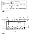
- FIG. 1 the reactions and transport processes are shown in a degassing process.
- a gas phase GAS located above the liquid sulfur S (Iq.).
- H 2 S can be transported by diffusion through three different exchange surfaces in the gas phase, namely 1: the stripping of the liquid sulfur with gas bubbles, 2: the sputtering of liquid sulfur in the above the liquid phase gas phase and 3: at the interface between liquid and gaseous phase.
- 1 the stripping of the liquid sulfur with gas bubbles
- 2 the sputtering of liquid sulfur in the above the liquid phase gas phase
- 3 at the interface between liquid and gaseous phase.
- H 2 S from the gas phase into the liquid phase via the gas / liquid interface.
- SO 2 can be transferred from the liquid phase to the gas phase in the same way.
- Hydrogen sulphide can be converted from GAS, which contains oxygen, by reaction with water, sulfur, SO 2 and SO 3 . Similar reactions also occur with polyhydric hydrogen and oxygen.
- FIG. 2 shows the embodiment of the batch process for a batch process in a batch reactor.
- This reactor has a container 1 which divides into the two regions 2 and 3.
- the region 2 is flooded with liquid sulfur as the first region, while the second region 3 is flooded with gas.
- first area 2 leads a line 11 through which a system for injection of stripping gas is fed with the stripping gas.
- This injection device 12 has a plurality of nozzles to produce a fine dispersion of strip gas in the liquid sulfur.
- the second region 3 is flushed with gas, which flows in via a line 13 and escapes via line 14.
- the gas flows essentially parallel to the surface of the liquid sulfur.
- the container is filled with liquid sulfur. This filling is not continuous, but at the beginning of the process.
- About the Pumping system 21 can be withdrawn via line 22 and 24 the first region of liquid sulfur and fed to a sputtering device 25. This atomizing device opens into the second region 3 and atomizes there the liquid sulfur from the first region 2 into the second region 3 flooded with a gas mixture.
- the liquid sulfur can be pumped out of the container 1 via line 22 and line 23 with the aid of the pump 21.
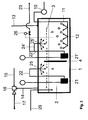
- FIG. 3 shows the embodiment of a system for carrying out a continuous process.
- the process takes place in a container 1, which has a flooded with liquid sulfur first region 2 and a gas-flooded second region 3.
- the container 1 is divided by a partition wall 4 into two chambers a, b, wherein the partition wall 4 is not flush, so that both below and above the partition wall 4, the two chambers a, b are connected to each other via openings.
- the opening near the bottom allows the sulfur to flow continuously from chamber a to chamber b;
- the purge gas preferably in countercurrent, can flow from chamber b to chamber a via the opening above the dividing wall.
- a stripping gas is fed to the injection device 12 through which stripping gas is blown into the second chamber with a plurality of nozzles.
- the injection for the stripping gas is provided at the bottom of the second chamber, but it is also possible to perform the injection in the first chamber or in both chambers.
- the embodiment shown has the advantage that in the first chamber, the amounts of dissolved hydrogen sulfide and the Polyschwefelwasserstoffe have been lowered and only to achieve the legally prescribed limit of remaining H 2 S in the degassed sulfur in the second chamber, the additional sparging is made. This will be the Reduced number of required natural perlungsvorraumen, when using air as little oxygen in the system registered and simultaneously achieved a sufficiently good result.
- a gas stream is further introduced into the second gas-flooded area 3, which flows from the second chamber b in countercurrent to the flow direction of the liquid sulfur in the first chamber a, from which it is withdrawn via line 14.
- the withdrawal takes place via a corresponding extraction device, preferably a steam jet, which is fed via line 15.
- the contained mixture of the gas streams and gaseous H 2 S is then discharged via line 17.
- Liquid sulfur is continuously introduced via line 20 into the first chamber a of the liquid sulfur flooded first region 2.
- a pump 21 which deducted via line 22 from the first region 2 liquid sulfur and this the atomizing device 25 supplies.
- This sputtering device 25 is located in the gas-flooded second region 3 of the first chamber.
- the partially vented in chamber a liquid sulfur then flows in through the arranged near the bottom opening of the partition wall 4 in the chamber b.
- a pump 21 ' which removes via line 22' liquid sulfur from the first region 2 of the second chamber.
- This is partially supplied via line 24 'to a second atomizing device 25' which atomizes liquid sulfur in the gas phase 3 of the second chamber.
- liquid sulfur is withdrawn via line 23 from the system, wherein the withdrawn amount corresponds to the amount supplied.
- a control device for example a level control valve 26, the withdrawn amount of liquid sulfur from the region 2 of the container can be regulated so that the withdrawal amount is so small that the total residence time of the sulfur is sufficient to meet the required statutory specification of ⁇ 10 ppm by weight H 2 S.
- supply of sulfur via line 20 can be controlled or controlled.
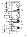
- Fig. 4 shows a continuous process according to the invention for the simultaneous degassing of H 2 S and SO 2 .
- This process is also carried out in a container 1 which has a sulfur-flooded first region 2 and a gas-flooded second region 3.
- the container is divided by two partitions 4 and 5 into three chambers a, b and c, the first two chambers a and b being used for the H 2 S removal and the third chamber c being intended for SO 2 removal.
- the partitions 4 and 5 are mounted so that openings below and above the partitions arise by no delimitation available and so a free flow of gas or sulfur is possible, with sulfur and gas are preferably conducted in countercurrent.
- a first stripping gas preferably air
- the injection device 12 conveniently a plurality of nozzles supplied.
- This introduction of the stripping gas takes place in the second chamber b.
- a gas stream is blown into the second gas-filled area 3 via line 13.
- the total flow of gases that are introduced via lines 11 and 13, then flows through the area 3 of the chamber a and is discharged via line 14 again from the container 1 and also carries the deducted from the liquid sulfur H 2 S from.
- This line 14 opens into a discharge device 16, which is preferably designed as a steam jet or ejector, which is fed by line 15 with the propellant. Via line 17 then the total amount of gas of the process can be finally discharged.
- a liquid, to be degassed sulfur is introduced into the first chamber a.
- This sulfur is recirculated in the first chamber a via the pump 21 in line 22, which opens into an atomizing device 25.
- These Atomizing device 25 is located in the second region 3 of the first chamber a.
- the device according to the invention also includes a third chamber c for the removal of SO 2 , which in the same way is equipped with a sputtering and recirculation pump 21 "which feeds the sputtering device 25" via line 22 "and line 24.
- the sputtering device 25 is provided in the gas phase 3 of the third chamber c. At the same time can be withdrawn from the container 1 via line 22 "and 23 parts of the liquid sulfur, which is now degassed.
- the flow of degassed sulfur, which is withdrawn, corresponds to the amount of supplied via line 20 raw sulfur. This can be done via a control device such as the level control valve 26 in the outlet line 23. This control valve continuously adjusts the level in the container 1 so that that residence time is set, which is necessary to achieve the legally prescribed specifications of remaining residual H 2 S and -SO 2 .
- a stripping gas is introduced into a injection device 31 in the third chamber c via line 30.
- This injection device 31 is equipped with a plurality of nozzles at the bottom of the liquid phase and thus ensures a suitable dispersion of the stripping gas through the sulfur mass.
- This stripping gas is an inert gas, such as nitrogen, while air is blown in through the blower 10 and line 11.
- the gas stream introduced via the line 13 is preferably air.
- the strip gas of the chamber c is introduced via line 30. After bubbling the liquid sulfur in chamber c, it enters the gas phase of chamber b. There it mixes with the inflowing strip gas introduced via line 11 into chamber b and the purge gas introduced via line 13, preferably in countercurrent flow. The resulting gas mixture is then passed to the gas phase of the chamber a.
- the total flow of the gases introduced into the container is withdrawn via a suitable extraction device 16, this extraction device 16 is preferably designed as a steam jet, which is fed via line 15 with steam. The entire gas mixture containing the removed H 2 S and SO 2 is then removed via line 17.
Landscapes
- Chemical & Material Sciences (AREA)
- Organic Chemistry (AREA)
- Inorganic Chemistry (AREA)
- Chemical Kinetics & Catalysis (AREA)
- Degasification And Air Bubble Elimination (AREA)
- Gas Separation By Absorption (AREA)
- Treating Waste Gases (AREA)
- Physical Water Treatments (AREA)
- Physical Or Chemical Processes And Apparatus (AREA)
- Filling Or Discharging Of Gas Storage Vessels (AREA)
Priority Applications (9)
| Application Number | Priority Date | Filing Date | Title |
|---|---|---|---|
| ES11290609.4T ES2539368T3 (es) | 2011-12-23 | 2011-12-23 | Procedimiento y dispositivo para la desgasificación de azufre líquido |
| PL11290609T PL2607304T3 (pl) | 2011-12-23 | 2011-12-23 | Metoda i urządzenie do odgazowywania ciekłej siarki |
| EP11290609.4A EP2607304B1 (de) | 2011-12-23 | 2011-12-23 | Verfahren und Vorrichtung zur Entgasung von flüssigem Schwefel |
| DE102012005450A DE102012005450B4 (de) | 2011-12-23 | 2012-03-20 | Verfahren und Vorrichtung zur Entgasung von flüssigem Schwefel |
| PCT/EP2012/071808 WO2013091972A1 (de) | 2011-12-23 | 2012-11-05 | Verfahren und vorrichtung zur entgasung von flüssigem schwefel |
| RU2014130137A RU2629077C2 (ru) | 2011-12-23 | 2012-11-05 | Способ и устройство для дегазации жидкой серы |
| US14/368,180 US10131542B2 (en) | 2011-12-23 | 2012-11-05 | Method and device for degassing liquid sulphur |
| CN201280062999.1A CN104114481B (zh) | 2011-12-23 | 2012-11-05 | 用于将液态硫脱气的方法和装置 |
| IN924MUN2014 IN2014MN00924A (cg-RX-API-DMAC7.html) | 2011-12-23 | 2012-11-05 |
Applications Claiming Priority (1)
| Application Number | Priority Date | Filing Date | Title |
|---|---|---|---|
| EP11290609.4A EP2607304B1 (de) | 2011-12-23 | 2011-12-23 | Verfahren und Vorrichtung zur Entgasung von flüssigem Schwefel |
Publications (2)
| Publication Number | Publication Date |
|---|---|
| EP2607304A1 EP2607304A1 (de) | 2013-06-26 |
| EP2607304B1 true EP2607304B1 (de) | 2015-03-25 |
Family
ID=47137716
Family Applications (1)
| Application Number | Title | Priority Date | Filing Date |
|---|---|---|---|
| EP11290609.4A Not-in-force EP2607304B1 (de) | 2011-12-23 | 2011-12-23 | Verfahren und Vorrichtung zur Entgasung von flüssigem Schwefel |
Country Status (9)
| Country | Link |
|---|---|
| US (1) | US10131542B2 (cg-RX-API-DMAC7.html) |
| EP (1) | EP2607304B1 (cg-RX-API-DMAC7.html) |
| CN (1) | CN104114481B (cg-RX-API-DMAC7.html) |
| DE (1) | DE102012005450B4 (cg-RX-API-DMAC7.html) |
| ES (1) | ES2539368T3 (cg-RX-API-DMAC7.html) |
| IN (1) | IN2014MN00924A (cg-RX-API-DMAC7.html) |
| PL (1) | PL2607304T3 (cg-RX-API-DMAC7.html) |
| RU (1) | RU2629077C2 (cg-RX-API-DMAC7.html) |
| WO (1) | WO2013091972A1 (cg-RX-API-DMAC7.html) |
Cited By (2)
| Publication number | Priority date | Publication date | Assignee | Title |
|---|---|---|---|---|
| US10059588B2 (en) | 2015-10-05 | 2018-08-28 | Fluor Technologies Corporation | Systems and methods for degassing of sulfur |
| US11713246B2 (en) | 2019-03-15 | 2023-08-01 | Fluor Technologies Corporation | Liquid sulfur degassing |
Families Citing this family (10)
| Publication number | Priority date | Publication date | Assignee | Title |
|---|---|---|---|---|
| DE102017001093A1 (de) | 2016-04-07 | 2017-10-26 | Entex Rust & Mitschke Gmbh | Entgasen bei der Extrusion von Kunststoffen mit Filterscheiben aus Sintermetall |
| DE102015001167A1 (de) | 2015-02-02 | 2016-08-04 | Entex Rust & Mitschke Gmbh | Entgasen bei der Extrusion von Kunststoffen |
| DE102017004563A1 (de) | 2017-03-05 | 2018-09-06 | Entex Rust & Mitschke Gmbh | Entgasen beim Extrudieren von Polymeren |
| CN107083316A (zh) * | 2017-05-22 | 2017-08-22 | 浙江农林大学 | 一种去除葡萄酒中二氧化硫的装置及其使用方法 |
| DE102018001412A1 (de) | 2017-12-11 | 2019-06-13 | Entex Rust & Mitschke Gmbh | Entgasen beim Extrudieren von Stoffen, vorzugsweise von Kunststoffen |
| DE102018206313A1 (de) * | 2018-04-24 | 2019-10-24 | Krones Ag | Entgasungsanlage und Verfahren zum Durchführen eines Entgasungsprozesses einer Flüssigkeit und Getränkebehandlungsmaschine |
| US10836637B2 (en) * | 2018-07-31 | 2020-11-17 | Controls Southeast, Inc. | Contactor apparatus and method of use |
| CN111474291B (zh) * | 2019-01-23 | 2022-08-30 | 中国石油天然气股份有限公司 | 一种液体硫磺中总硫化氢含量的催化剂化学测定方法 |
| CN111420430B (zh) * | 2020-04-10 | 2024-12-10 | 上海蓝滨石化设备有限责任公司 | 一种液硫脱气装置及其组成的橇装集成设备 |
| CN115724407B (zh) * | 2021-08-31 | 2024-07-16 | 中国石油化工股份有限公司 | 一种液硫脱气装置及方法 |
Family Cites Families (16)
| Publication number | Priority date | Publication date | Assignee | Title |
|---|---|---|---|---|
| NL173735C (nl) * | 1972-05-24 | 1988-06-16 | Shell Int Research | Werkwijze voor het verwijderen van waterstofsulfide uit gesmolten zwavel. |
| US4131437A (en) * | 1975-12-19 | 1978-12-26 | Exxon Research & Engineering Co. | Process for the continuous multistage degasification of liquid sulfur |
| DE2842141A1 (de) | 1978-09-28 | 1980-04-10 | Union Rheinische Braunkohlen | Verfahren zur entfernung von schwefelwasserstoff aus fluessigem schwefel |
| DE3417230A1 (de) | 1984-05-10 | 1985-11-14 | Metallgesellschaft Ag, 6000 Frankfurt | Verfahren und vorrichtung zum entgasen von schwefelwasserstoffhaltigem fluessigem schwefel |
| FR2601350B1 (fr) | 1986-07-10 | 1988-09-30 | Elf Aquitaine | Procede pour l'elimination rapide de l'hydrogene sulfure contenu dans le soufre liquide et systeme catalytique utilisable pour sa mise en oeuvre |
| JPS63222005A (ja) * | 1987-03-09 | 1988-09-14 | Jgc Corp | 粗製液体硫黄の精製方法 |
| DE4331126A1 (de) | 1993-09-14 | 1995-03-16 | Ruhr Oel Gmbh | Verfahren zur Entfernung von Schwefelwasserstoff aus flüssigem Schwefel |
| CA2160412A1 (en) * | 1994-10-13 | 1996-04-14 | Adolf Frederik Scheybeler | Method and apparatus for degassing sulphur |
| NL1003085C2 (nl) * | 1995-09-15 | 1997-03-20 | Stork Comprimo Bv | Werkwijze en inrichting voor het ontgassen van zwavel. |
| US5632967A (en) * | 1995-09-19 | 1997-05-27 | Goar, Allison & Associates, Inc. | Process for the high pressure degassing of hydrogen sulfide from liquid sulfur |
| US6676918B2 (en) | 2002-06-14 | 2004-01-13 | Exxonmobil Research And Engineering Company | Hydrogen sulfide removal from liquid sulfur |
| US7081233B2 (en) * | 2004-05-18 | 2006-07-25 | Dynamax Engineering Ltd. | Method and apparatus for degassing liquid sulfur |
| RU2353576C2 (ru) * | 2006-12-04 | 2009-04-27 | Антон Александрович Пшегорский | Способ дегазации жидкой серы |
| US7927577B2 (en) | 2009-01-12 | 2011-04-19 | Worleyparsons Group, Inc. | Sulfur collection systems and processes with integrated degassing |
| US8084013B2 (en) * | 2009-07-22 | 2011-12-27 | Kps Technology & Engineering Llc | Method and apparatus for degasification of claus-derived sulfur |
| US8663596B2 (en) * | 2010-01-25 | 2014-03-04 | Fluor Enterprises, Inc. | Reactor, a structure packing, and a method for improving oxidation of hydrogen sulfide or polysulfides in liquid sulfur |
-
2011
- 2011-12-23 PL PL11290609T patent/PL2607304T3/pl unknown
- 2011-12-23 ES ES11290609.4T patent/ES2539368T3/es active Active
- 2011-12-23 EP EP11290609.4A patent/EP2607304B1/de not_active Not-in-force
-
2012
- 2012-03-20 DE DE102012005450A patent/DE102012005450B4/de not_active Expired - Fee Related
- 2012-11-05 US US14/368,180 patent/US10131542B2/en not_active Expired - Fee Related
- 2012-11-05 IN IN924MUN2014 patent/IN2014MN00924A/en unknown
- 2012-11-05 CN CN201280062999.1A patent/CN104114481B/zh not_active Expired - Fee Related
- 2012-11-05 RU RU2014130137A patent/RU2629077C2/ru active
- 2012-11-05 WO PCT/EP2012/071808 patent/WO2013091972A1/de not_active Ceased
Cited By (3)
| Publication number | Priority date | Publication date | Assignee | Title |
|---|---|---|---|---|
| US10059588B2 (en) | 2015-10-05 | 2018-08-28 | Fluor Technologies Corporation | Systems and methods for degassing of sulfur |
| US11034583B2 (en) | 2015-10-05 | 2021-06-15 | Fluor Technologies Corporation | Systems and methods for degassing of sulfur |
| US11713246B2 (en) | 2019-03-15 | 2023-08-01 | Fluor Technologies Corporation | Liquid sulfur degassing |
Also Published As
| Publication number | Publication date |
|---|---|
| WO2013091972A1 (de) | 2013-06-27 |
| DE102012005450B4 (de) | 2013-07-04 |
| US20140366731A1 (en) | 2014-12-18 |
| ES2539368T3 (es) | 2015-06-30 |
| IN2014MN00924A (cg-RX-API-DMAC7.html) | 2015-04-17 |
| RU2014130137A (ru) | 2016-02-20 |
| CN104114481A (zh) | 2014-10-22 |
| RU2629077C2 (ru) | 2017-08-24 |
| PL2607304T3 (pl) | 2015-08-31 |
| EP2607304A1 (de) | 2013-06-26 |
| CN104114481B (zh) | 2017-02-22 |
| DE102012005450A1 (de) | 2013-06-27 |
| US10131542B2 (en) | 2018-11-20 |
Similar Documents
| Publication | Publication Date | Title |
|---|---|---|
| EP2607304B1 (de) | Verfahren und Vorrichtung zur Entgasung von flüssigem Schwefel | |
| DE69630797T2 (de) | Verfahren und vorrichtung zur entgasung von schwefel | |
| DE69606186T2 (de) | Verfahren zur entfernung von schwefelwasserstoff aus flüssigem schwefel mittels hochdruckentgasung | |
| DE102007050904B4 (de) | Anlage und Verfahren zur Reinigung von Rauchgasen | |
| DE2708497A1 (de) | Verfahren und vorrichtung zur entfernung von verunreinigungen aus einem abgas oder rauchgas | |
| EP0164140B1 (de) | Verfahren und Vorrichtung zum Entgasen von schwefelwasserstoffhaltigem flüssigem Schwefel | |
| DE69502712T2 (de) | Verfahren und vorrichtung zur behandlung von abwässern, die organische stoffe enthalten, insbesondere durch nassoxydation mit interner feststoffrückführung und kläranlage zur durchführung des verfahrens. | |
| DE1934479A1 (de) | Verfahren und Vorrichtung zur Extraktion eines Gases aus einem Gasgemisch | |
| DE2059415A1 (de) | Verfahren zum Herstellen einer innigen Mischung einer Fluessigkeit und eines Gases,insbesondere zur wechselseitigen Entgiftung von Verbrennungsabgasen in Ablaugen | |
| DE2237179A1 (de) | Verfahren und vorrichtung zur entfernung von schwefelwasserstoff und mercaptanen aus fluessigkeits- und gasstroemen | |
| DE2254375C2 (de) | Verfahren zum Entgasen von flüssigem Schwefel | |
| CH617867A5 (cg-RX-API-DMAC7.html) | ||
| DE2221022A1 (de) | Verfahren zur Herabsetzung der in fluessigem Schwefel geloesten Schwefelwasserstoffmenge waehrend des Pumpens durch eine Rohrleitung | |
| EP3338883B1 (de) | Vorrichtung und verfahren zum eintragen von gas in eine mehrzahl von prozessfluiden | |
| DE3515709C1 (de) | Verfahren zum Reinigen von fluessigem Schwefel | |
| DE2756186A1 (de) | Verfahren zur verringerung der konzentration an stickstoffoxid in abgasen durch ultraviolettbestrahlung | |
| DE3009724A1 (de) | Verfahren zur behandlung eines stickoxide enthaltenden gasstroms | |
| AT405721B (de) | Vorrichtung zum abtrennen von gasen aus flüssigkeiten sowie verwendung der vorrichtung zur abtrennung von schwefelwasserstoff aus flüssigem schwefel | |
| DE4042210A1 (de) | Verfahren zur beseitigung von arsenik und anderen metallen aus abwaessern von industrieanlagen durch behandlung mit sulphydrit unter druck und anlage zur durchfuehrung des verfahrens | |
| DE2650407A1 (de) | Abscheidung von schwefelwasserstoff und mercaptanen aus gasen | |
| DE109484C (cg-RX-API-DMAC7.html) | ||
| EP3008036B1 (de) | Verfahren und vorrichtung zur entfernung von bei der herstellung von aliphatischen nitratestern anfallenden verunreinigungen | |
| EP3912958B1 (de) | Verfahren und produktionsanlage zum herstellen von salpetersäure | |
| EP3165505A1 (de) | Verfahren zur herstellung von peroxosalpetersäure | |
| EP1923124A1 (de) | Verfahren zur Reinigung von nitrose Gase enthaltenden Abgasen |
Legal Events
| Date | Code | Title | Description |
|---|---|---|---|
| AK | Designated contracting states |
Kind code of ref document: A1 Designated state(s): AL AT BE BG CH CY CZ DE DK EE ES FI FR GB GR HR HU IE IS IT LI LT LU LV MC MK MT NL NO PL PT RO RS SE SI SK SM TR |
|
| AX | Request for extension of the european patent |
Extension state: BA ME |
|
| PUAI | Public reference made under article 153(3) epc to a published international application that has entered the european phase |
Free format text: ORIGINAL CODE: 0009012 |
|
| 17P | Request for examination filed |
Effective date: 20131106 |
|
| RBV | Designated contracting states (corrected) |
Designated state(s): AL AT BE BG CH CY CZ DE DK EE ES FI FR GB GR HR HU IE IS IT LI LT LU LV MC MK MT NL NO PL PT RO RS SE SI SK SM TR |
|
| 17Q | First examination report despatched |
Effective date: 20140205 |
|
| RAP1 | Party data changed (applicant data changed or rights of an application transferred) |
Owner name: NOUGAYREDE, JEAN Owner name: AIR LIQUIDE GLOBAL E&C SOLUTIONS GERMANY GMBH |
|
| RAP1 | Party data changed (applicant data changed or rights of an application transferred) |
Owner name: AIR LIQUIDE GLOBAL E&C SOLUTIONS GERMANY GMBH Owner name: NGD CONSULT |
|
| GRAP | Despatch of communication of intention to grant a patent |
Free format text: ORIGINAL CODE: EPIDOSNIGR1 |
|
| INTG | Intention to grant announced |
Effective date: 20141124 |
|
| GRAS | Grant fee paid |
Free format text: ORIGINAL CODE: EPIDOSNIGR3 |
|
| GRAA | (expected) grant |
Free format text: ORIGINAL CODE: 0009210 |
|
| AK | Designated contracting states |
Kind code of ref document: B1 Designated state(s): AL AT BE BG CH CY CZ DE DK EE ES FI FR GB GR HR HU IE IS IT LI LT LU LV MC MK MT NL NO PL PT RO RS SE SI SK SM TR |
|
| REG | Reference to a national code |
Ref country code: GB Ref legal event code: FG4D Free format text: NOT ENGLISH |
|
| REG | Reference to a national code |
Ref country code: CH Ref legal event code: EP |
|
| REG | Reference to a national code |
Ref country code: IE Ref legal event code: FG4D Free format text: LANGUAGE OF EP DOCUMENT: GERMAN |
|
| REG | Reference to a national code |
Ref country code: DE Ref legal event code: R096 Ref document number: 502011006367 Country of ref document: DE Effective date: 20150507 |
|
| REG | Reference to a national code |
Ref country code: AT Ref legal event code: REF Ref document number: 717768 Country of ref document: AT Kind code of ref document: T Effective date: 20150515 |
|
| REG | Reference to a national code |
Ref country code: ES Ref legal event code: FG2A Ref document number: 2539368 Country of ref document: ES Kind code of ref document: T3 Effective date: 20150630 |
|
| REG | Reference to a national code |
Ref country code: NL Ref legal event code: T3 |
|
| PG25 | Lapsed in a contracting state [announced via postgrant information from national office to epo] |
Ref country code: LT Free format text: LAPSE BECAUSE OF FAILURE TO SUBMIT A TRANSLATION OF THE DESCRIPTION OR TO PAY THE FEE WITHIN THE PRESCRIBED TIME-LIMIT Effective date: 20150325 Ref country code: SE Free format text: LAPSE BECAUSE OF FAILURE TO SUBMIT A TRANSLATION OF THE DESCRIPTION OR TO PAY THE FEE WITHIN THE PRESCRIBED TIME-LIMIT Effective date: 20150325 Ref country code: FI Free format text: LAPSE BECAUSE OF FAILURE TO SUBMIT A TRANSLATION OF THE DESCRIPTION OR TO PAY THE FEE WITHIN THE PRESCRIBED TIME-LIMIT Effective date: 20150325 Ref country code: HR Free format text: LAPSE BECAUSE OF FAILURE TO SUBMIT A TRANSLATION OF THE DESCRIPTION OR TO PAY THE FEE WITHIN THE PRESCRIBED TIME-LIMIT Effective date: 20150325 |
|
| REG | Reference to a national code |
Ref country code: LT Ref legal event code: MG4D |
|
| PG25 | Lapsed in a contracting state [announced via postgrant information from national office to epo] |
Ref country code: LV Free format text: LAPSE BECAUSE OF FAILURE TO SUBMIT A TRANSLATION OF THE DESCRIPTION OR TO PAY THE FEE WITHIN THE PRESCRIBED TIME-LIMIT Effective date: 20150325 Ref country code: GR Free format text: LAPSE BECAUSE OF FAILURE TO SUBMIT A TRANSLATION OF THE DESCRIPTION OR TO PAY THE FEE WITHIN THE PRESCRIBED TIME-LIMIT Effective date: 20150626 Ref country code: RS Free format text: LAPSE BECAUSE OF FAILURE TO SUBMIT A TRANSLATION OF THE DESCRIPTION OR TO PAY THE FEE WITHIN THE PRESCRIBED TIME-LIMIT Effective date: 20150325 |
|
| REG | Reference to a national code |
Ref country code: PL Ref legal event code: T3 |
|
| PG25 | Lapsed in a contracting state [announced via postgrant information from national office to epo] |
Ref country code: PT Free format text: LAPSE BECAUSE OF FAILURE TO SUBMIT A TRANSLATION OF THE DESCRIPTION OR TO PAY THE FEE WITHIN THE PRESCRIBED TIME-LIMIT Effective date: 20150727 Ref country code: RO Free format text: LAPSE BECAUSE OF FAILURE TO SUBMIT A TRANSLATION OF THE DESCRIPTION OR TO PAY THE FEE WITHIN THE PRESCRIBED TIME-LIMIT Effective date: 20150325 Ref country code: EE Free format text: LAPSE BECAUSE OF FAILURE TO SUBMIT A TRANSLATION OF THE DESCRIPTION OR TO PAY THE FEE WITHIN THE PRESCRIBED TIME-LIMIT Effective date: 20150325 Ref country code: SK Free format text: LAPSE BECAUSE OF FAILURE TO SUBMIT A TRANSLATION OF THE DESCRIPTION OR TO PAY THE FEE WITHIN THE PRESCRIBED TIME-LIMIT Effective date: 20150325 |
|
| PG25 | Lapsed in a contracting state [announced via postgrant information from national office to epo] |
Ref country code: IS Free format text: LAPSE BECAUSE OF FAILURE TO SUBMIT A TRANSLATION OF THE DESCRIPTION OR TO PAY THE FEE WITHIN THE PRESCRIBED TIME-LIMIT Effective date: 20150725 |
|
| REG | Reference to a national code |
Ref country code: FR Ref legal event code: PLFP Year of fee payment: 5 |
|
| REG | Reference to a national code |
Ref country code: DE Ref legal event code: R097 Ref document number: 502011006367 Country of ref document: DE |
|
| PG25 | Lapsed in a contracting state [announced via postgrant information from national office to epo] |
Ref country code: DK Free format text: LAPSE BECAUSE OF FAILURE TO SUBMIT A TRANSLATION OF THE DESCRIPTION OR TO PAY THE FEE WITHIN THE PRESCRIBED TIME-LIMIT Effective date: 20150325 |
|
| PLBE | No opposition filed within time limit |
Free format text: ORIGINAL CODE: 0009261 |
|
| STAA | Information on the status of an ep patent application or granted ep patent |
Free format text: STATUS: NO OPPOSITION FILED WITHIN TIME LIMIT |
|
| 26N | No opposition filed |
Effective date: 20160105 |
|
| PG25 | Lapsed in a contracting state [announced via postgrant information from national office to epo] |
Ref country code: SI Free format text: LAPSE BECAUSE OF FAILURE TO SUBMIT A TRANSLATION OF THE DESCRIPTION OR TO PAY THE FEE WITHIN THE PRESCRIBED TIME-LIMIT Effective date: 20150325 |
|
| PG25 | Lapsed in a contracting state [announced via postgrant information from national office to epo] |
Ref country code: MC Free format text: LAPSE BECAUSE OF FAILURE TO SUBMIT A TRANSLATION OF THE DESCRIPTION OR TO PAY THE FEE WITHIN THE PRESCRIBED TIME-LIMIT Effective date: 20150325 Ref country code: LU Free format text: LAPSE BECAUSE OF FAILURE TO SUBMIT A TRANSLATION OF THE DESCRIPTION OR TO PAY THE FEE WITHIN THE PRESCRIBED TIME-LIMIT Effective date: 20151223 |
|
| REG | Reference to a national code |
Ref country code: CH Ref legal event code: PL |
|
| REG | Reference to a national code |
Ref country code: IE Ref legal event code: MM4A |
|
| PG25 | Lapsed in a contracting state [announced via postgrant information from national office to epo] |
Ref country code: IE Free format text: LAPSE BECAUSE OF NON-PAYMENT OF DUE FEES Effective date: 20151223 Ref country code: CH Free format text: LAPSE BECAUSE OF NON-PAYMENT OF DUE FEES Effective date: 20151231 Ref country code: LI Free format text: LAPSE BECAUSE OF NON-PAYMENT OF DUE FEES Effective date: 20151231 |
|
| REG | Reference to a national code |
Ref country code: FR Ref legal event code: PLFP Year of fee payment: 6 |
|
| PG25 | Lapsed in a contracting state [announced via postgrant information from national office to epo] |
Ref country code: NO Free format text: LAPSE BECAUSE OF FAILURE TO SUBMIT A TRANSLATION OF THE DESCRIPTION OR TO PAY THE FEE WITHIN THE PRESCRIBED TIME-LIMIT Effective date: 20150625 Ref country code: HU Free format text: LAPSE BECAUSE OF FAILURE TO SUBMIT A TRANSLATION OF THE DESCRIPTION OR TO PAY THE FEE WITHIN THE PRESCRIBED TIME-LIMIT; INVALID AB INITIO Effective date: 20111223 Ref country code: SM Free format text: LAPSE BECAUSE OF FAILURE TO SUBMIT A TRANSLATION OF THE DESCRIPTION OR TO PAY THE FEE WITHIN THE PRESCRIBED TIME-LIMIT Effective date: 20150325 Ref country code: BG Free format text: LAPSE BECAUSE OF FAILURE TO SUBMIT A TRANSLATION OF THE DESCRIPTION OR TO PAY THE FEE WITHIN THE PRESCRIBED TIME-LIMIT Effective date: 20150325 |
|
| PG25 | Lapsed in a contracting state [announced via postgrant information from national office to epo] |
Ref country code: CY Free format text: LAPSE BECAUSE OF FAILURE TO SUBMIT A TRANSLATION OF THE DESCRIPTION OR TO PAY THE FEE WITHIN THE PRESCRIBED TIME-LIMIT Effective date: 20150325 |
|
| PG25 | Lapsed in a contracting state [announced via postgrant information from national office to epo] |
Ref country code: MT Free format text: LAPSE BECAUSE OF FAILURE TO SUBMIT A TRANSLATION OF THE DESCRIPTION OR TO PAY THE FEE WITHIN THE PRESCRIBED TIME-LIMIT Effective date: 20150325 |
|
| REG | Reference to a national code |
Ref country code: FR Ref legal event code: PLFP Year of fee payment: 7 |
|
| REG | Reference to a national code |
Ref country code: AT Ref legal event code: MM01 Ref document number: 717768 Country of ref document: AT Kind code of ref document: T Effective date: 20161223 |
|
| PG25 | Lapsed in a contracting state [announced via postgrant information from national office to epo] |
Ref country code: AT Free format text: LAPSE BECAUSE OF NON-PAYMENT OF DUE FEES Effective date: 20161223 |
|
| PG25 | Lapsed in a contracting state [announced via postgrant information from national office to epo] |
Ref country code: MK Free format text: LAPSE BECAUSE OF FAILURE TO SUBMIT A TRANSLATION OF THE DESCRIPTION OR TO PAY THE FEE WITHIN THE PRESCRIBED TIME-LIMIT Effective date: 20150325 Ref country code: TR Free format text: LAPSE BECAUSE OF FAILURE TO SUBMIT A TRANSLATION OF THE DESCRIPTION OR TO PAY THE FEE WITHIN THE PRESCRIBED TIME-LIMIT Effective date: 20150325 |
|
| PG25 | Lapsed in a contracting state [announced via postgrant information from national office to epo] |
Ref country code: AL Free format text: LAPSE BECAUSE OF FAILURE TO SUBMIT A TRANSLATION OF THE DESCRIPTION OR TO PAY THE FEE WITHIN THE PRESCRIBED TIME-LIMIT Effective date: 20150325 |
|
| REG | Reference to a national code |
Ref country code: DE Ref legal event code: R082 Ref document number: 502011006367 Country of ref document: DE Representative=s name: KEIL & SCHAAFHAUSEN PATENTANWAELTE PARTGMBB, DE Ref country code: DE Ref legal event code: R082 Ref document number: 502011006367 Country of ref document: DE Representative=s name: KEIL & SCHAAFHAUSEN PATENT- UND RECHTSANWAELTE, DE Ref country code: DE Ref legal event code: R081 Ref document number: 502011006367 Country of ref document: DE Owner name: NGD CONSULT S.A.R.L., FR Free format text: FORMER OWNERS: AIR LIQUIDE GLOBAL E&C SOLUTIONS GERMANY GMBH, 60439 FRANKFURT, DE; NGD CONSULT, PAU, FR |
|
| REG | Reference to a national code |
Ref country code: NL Ref legal event code: PD Owner name: NGD CONSULT SARL; FR Free format text: DETAILS ASSIGNMENT: CHANGE OF OWNER(S), ASSIGNMENT; FORMER OWNER NAME: NGD CONSULT SARL Effective date: 20191003 Ref country code: NL Ref legal event code: HC Owner name: NGD CONSULT SARL; FR Free format text: DETAILS ASSIGNMENT: CHANGE OF OWNER(S), CHANGE OF OWNER(S) NAME; FORMER OWNER NAME: NGD CONSULT Effective date: 20191003 |
|
| REG | Reference to a national code |
Ref country code: GB Ref legal event code: 732E Free format text: REGISTERED BETWEEN 20190926 AND 20191002 |
|
| REG | Reference to a national code |
Ref country code: ES Ref legal event code: PC2A Owner name: NGD CONSULT Effective date: 20191022 |
|
| REG | Reference to a national code |
Ref country code: BE Ref legal event code: PD Owner name: NGD CONSULT; FR Free format text: DETAILS ASSIGNMENT: CHANGE OF OWNER(S), CESSION; FORMER OWNER NAME: NGD CONSULT Effective date: 20190917 Ref country code: BE Ref legal event code: HC Owner name: NGD CONSULT SARL; FR Free format text: DETAILS ASSIGNMENT: CHANGE OF OWNER(S), CHANGEMENT DE NOM DU PROPRIETAIRE, CORRECTION Effective date: 20190917 |
|
| PGFP | Annual fee paid to national office [announced via postgrant information from national office to epo] |
Ref country code: CZ Payment date: 20191219 Year of fee payment: 9 |
|
| PGFP | Annual fee paid to national office [announced via postgrant information from national office to epo] |
Ref country code: PL Payment date: 20191121 Year of fee payment: 9 |
|
| PGFP | Annual fee paid to national office [announced via postgrant information from national office to epo] |
Ref country code: ES Payment date: 20200623 Year of fee payment: 9 |
|
| PGFP | Annual fee paid to national office [announced via postgrant information from national office to epo] |
Ref country code: NL Payment date: 20200624 Year of fee payment: 9 Ref country code: GB Payment date: 20200609 Year of fee payment: 9 Ref country code: BE Payment date: 20200623 Year of fee payment: 9 |
|
| PGFP | Annual fee paid to national office [announced via postgrant information from national office to epo] |
Ref country code: DE Payment date: 20201229 Year of fee payment: 10 |
|
| PGFP | Annual fee paid to national office [announced via postgrant information from national office to epo] |
Ref country code: IT Payment date: 20201224 Year of fee payment: 10 |
|
| PG25 | Lapsed in a contracting state [announced via postgrant information from national office to epo] |
Ref country code: CZ Free format text: LAPSE BECAUSE OF NON-PAYMENT OF DUE FEES Effective date: 20201223 |
|
| PGFP | Annual fee paid to national office [announced via postgrant information from national office to epo] |
Ref country code: FR Payment date: 20210419 Year of fee payment: 10 |
|
| REG | Reference to a national code |
Ref country code: NL Ref legal event code: MM Effective date: 20210101 |
|
| GBPC | Gb: european patent ceased through non-payment of renewal fee |
Effective date: 20201223 |
|
| REG | Reference to a national code |
Ref country code: BE Ref legal event code: MM Effective date: 20201231 |
|
| PG25 | Lapsed in a contracting state [announced via postgrant information from national office to epo] |
Ref country code: NL Free format text: LAPSE BECAUSE OF NON-PAYMENT OF DUE FEES Effective date: 20210101 |
|
| PG25 | Lapsed in a contracting state [announced via postgrant information from national office to epo] |
Ref country code: GB Free format text: LAPSE BECAUSE OF NON-PAYMENT OF DUE FEES Effective date: 20201223 |
|
| REG | Reference to a national code |
Ref country code: ES Ref legal event code: FD2A Effective date: 20220412 |
|
| REG | Reference to a national code |
Ref country code: DE Ref legal event code: R119 Ref document number: 502011006367 Country of ref document: DE |
|
| PG25 | Lapsed in a contracting state [announced via postgrant information from national office to epo] |
Ref country code: ES Free format text: LAPSE BECAUSE OF NON-PAYMENT OF DUE FEES Effective date: 20201224 Ref country code: BE Free format text: LAPSE BECAUSE OF NON-PAYMENT OF DUE FEES Effective date: 20201231 |
|
| PG25 | Lapsed in a contracting state [announced via postgrant information from national office to epo] |
Ref country code: DE Free format text: LAPSE BECAUSE OF NON-PAYMENT OF DUE FEES Effective date: 20220701 |
|
| PG25 | Lapsed in a contracting state [announced via postgrant information from national office to epo] |
Ref country code: PL Free format text: LAPSE BECAUSE OF NON-PAYMENT OF DUE FEES Effective date: 20201223 Ref country code: FR Free format text: LAPSE BECAUSE OF NON-PAYMENT OF DUE FEES Effective date: 20211231 |
|
| PG25 | Lapsed in a contracting state [announced via postgrant information from national office to epo] |
Ref country code: IT Free format text: LAPSE BECAUSE OF NON-PAYMENT OF DUE FEES Effective date: 20211223 |