EP2605910B1 - Ensemble tête d'impression à jet d'encre à groupement large comportant un écran - Google Patents
Ensemble tête d'impression à jet d'encre à groupement large comportant un écran Download PDFInfo
- Publication number
- EP2605910B1 EP2605910B1 EP10856239.8A EP10856239A EP2605910B1 EP 2605910 B1 EP2605910 B1 EP 2605910B1 EP 10856239 A EP10856239 A EP 10856239A EP 2605910 B1 EP2605910 B1 EP 2605910B1
- Authority
- EP
- European Patent Office
- Prior art keywords
- die
- shroud
- printhead assembly
- array
- circuit board
- Prior art date
- Legal status (The legal status is an assumption and is not a legal conclusion. Google has not performed a legal analysis and makes no representation as to the accuracy of the status listed.)
- Active
Links
Images


Classifications
-
- B—PERFORMING OPERATIONS; TRANSPORTING
- B41—PRINTING; LINING MACHINES; TYPEWRITERS; STAMPS
- B41J—TYPEWRITERS; SELECTIVE PRINTING MECHANISMS, i.e. MECHANISMS PRINTING OTHERWISE THAN FROM A FORME; CORRECTION OF TYPOGRAPHICAL ERRORS
- B41J2/00—Typewriters or selective printing mechanisms characterised by the printing or marking process for which they are designed
- B41J2/005—Typewriters or selective printing mechanisms characterised by the printing or marking process for which they are designed characterised by bringing liquid or particles selectively into contact with a printing material
- B41J2/01—Ink jet
- B41J2/135—Nozzles
- B41J2/165—Preventing or detecting of nozzle clogging, e.g. cleaning, capping or moistening for nozzles
- B41J2/16505—Caps, spittoons or covers for cleaning or preventing drying out
-
- B—PERFORMING OPERATIONS; TRANSPORTING
- B41—PRINTING; LINING MACHINES; TYPEWRITERS; STAMPS
- B41J—TYPEWRITERS; SELECTIVE PRINTING MECHANISMS, i.e. MECHANISMS PRINTING OTHERWISE THAN FROM A FORME; CORRECTION OF TYPOGRAPHICAL ERRORS
- B41J2/00—Typewriters or selective printing mechanisms characterised by the printing or marking process for which they are designed
- B41J2/005—Typewriters or selective printing mechanisms characterised by the printing or marking process for which they are designed characterised by bringing liquid or particles selectively into contact with a printing material
- B41J2/01—Ink jet
- B41J2/135—Nozzles
- B41J2/145—Arrangement thereof
- B41J2/155—Arrangement thereof for line printing
-
- B—PERFORMING OPERATIONS; TRANSPORTING
- B41—PRINTING; LINING MACHINES; TYPEWRITERS; STAMPS
- B41J—TYPEWRITERS; SELECTIVE PRINTING MECHANISMS, i.e. MECHANISMS PRINTING OTHERWISE THAN FROM A FORME; CORRECTION OF TYPOGRAPHICAL ERRORS
- B41J2/00—Typewriters or selective printing mechanisms characterised by the printing or marking process for which they are designed
- B41J2/005—Typewriters or selective printing mechanisms characterised by the printing or marking process for which they are designed characterised by bringing liquid or particles selectively into contact with a printing material
- B41J2/01—Ink jet
- B41J2/135—Nozzles
- B41J2/14—Structure thereof only for on-demand ink jet heads
- B41J2002/14362—Assembling elements of heads
-
- B—PERFORMING OPERATIONS; TRANSPORTING
- B41—PRINTING; LINING MACHINES; TYPEWRITERS; STAMPS
- B41J—TYPEWRITERS; SELECTIVE PRINTING MECHANISMS, i.e. MECHANISMS PRINTING OTHERWISE THAN FROM A FORME; CORRECTION OF TYPOGRAPHICAL ERRORS
- B41J2/00—Typewriters or selective printing mechanisms characterised by the printing or marking process for which they are designed
- B41J2/005—Typewriters or selective printing mechanisms characterised by the printing or marking process for which they are designed characterised by bringing liquid or particles selectively into contact with a printing material
- B41J2/01—Ink jet
- B41J2/135—Nozzles
- B41J2/14—Structure thereof only for on-demand ink jet heads
- B41J2002/14491—Electrical connection
-
- B—PERFORMING OPERATIONS; TRANSPORTING
- B41—PRINTING; LINING MACHINES; TYPEWRITERS; STAMPS
- B41J—TYPEWRITERS; SELECTIVE PRINTING MECHANISMS, i.e. MECHANISMS PRINTING OTHERWISE THAN FROM A FORME; CORRECTION OF TYPOGRAPHICAL ERRORS
- B41J2/00—Typewriters or selective printing mechanisms characterised by the printing or marking process for which they are designed
- B41J2/005—Typewriters or selective printing mechanisms characterised by the printing or marking process for which they are designed characterised by bringing liquid or particles selectively into contact with a printing material
- B41J2/01—Ink jet
- B41J2/135—Nozzles
- B41J2/165—Preventing or detecting of nozzle clogging, e.g. cleaning, capping or moistening for nozzles
- B41J2002/16502—Printhead constructions to prevent nozzle clogging or facilitate nozzle cleaning
-
- B—PERFORMING OPERATIONS; TRANSPORTING
- B41—PRINTING; LINING MACHINES; TYPEWRITERS; STAMPS
- B41J—TYPEWRITERS; SELECTIVE PRINTING MECHANISMS, i.e. MECHANISMS PRINTING OTHERWISE THAN FROM A FORME; CORRECTION OF TYPOGRAPHICAL ERRORS
- B41J2202/00—Embodiments of or processes related to ink-jet or thermal heads
- B41J2202/01—Embodiments of or processes related to ink-jet heads
- B41J2202/20—Modules
Definitions
- Wide-array inkjet printheads typically deposit ink across the width of a substrate as it is fed through the printer. Because the wide-array printheads are substantially as wide as the substrate, there is no need for translation of the printhead. However, the increased size of the wide-array inkjet printhead can also increase the number of components, increase the cost of the printhead, and lead to more stringent manufacturing tolerances.
- US 2010/0053265 discloses an array type inkjet printhead including an ink cartridge to store ink, at least one print head chip disposed on a base of the ink cartridge to project from the base, the at least one print head chip to fire the ink, a flat plate cover disposed on the base of the ink cartridge and to have at least one opening corresponding to the at least one print head chip, and an adhesive member disposed between the base of the ink cartridge and the flat plate cover to fix the flat plate cover to the base of the ink cartridge.
- the flat plate cover is formed of either a metal material or a ceramic material.
- Wide-array inkjet printheads typically deposit printing fluid across the width of a substrate as it is fed through the printer. Because the wide-array printheads are substantially as wide as the substrate, there is no need for translation of the printhead. However, the increased size of the wide-array inkjet printhead can also increase the number of components, increase the cost of the printhead, and lead to more stringent manufacturing tolerances.
- a wide-array inkjet printhead assembly is composed of an array of printhead die.
- These printhead die are among the highest precision components in the printhead assembly and contain the droplet ejection mechanisms.
- the printhead die may contain thermal, piezo, or MEMs ejection elements. These ejection elements are activated to force droplets of fluid out of an array of nozzles. These droplets may have a volume on the order of 1-30 picoliters.
- the droplets may take the form of ink droplets deposited on a substrate to create the desired image.
- a shroud can be placed around the array of inkjet die.
- the shroud serves a number of functions, including protecting the components it covers from damage/contamination and providing a capping surface that interfaces with a cap.
- the cap is placed onto the capping surface when the printhead assembly is not in use to create an enclosure over the die.
- the shroud and cap prevent the continued evaporation of the ink from the die. This prevents the accumulation of ink solids which could cause blockage or malfunctions of the inkjet die.
- the capping surface of the shroud meet a target profile specification.
- profile specification refers to a requirement that all points on a surface must lie between two planes which are at specified locations relative to a reference plane and a specified distance apart.
- a profile specification defines both the location of a surface and allowable deviations of the surface.
- a profile specification can be applied to both flat and curved surfaces. For example, a profile specification of 0.100 millimeters for a flat surface means that all points must lie within two parallel planes which are 0.100 millimeters apart.
- the specified distance can be defined in a number of ways, including a range or a percentage.
- the target profile specification may be between 0.5% and 0.05% of the overall length of the printhead assembly.
- the capping surface of the shroud which covers the die on the printhead assembly would be at least 210 millimeters in length.
- a profile specification of 0.2% requires that no part of the capping surface deviate from a reference plane by any more than ⁇ 0.21 millimeters.
- the target profile specification may be even more stringent depending on the application, cap design, width of the printhead assembly and other factors. For other applications the profile specification may be even more stringent.
- the target profile specification to achieve the desired seal between a cap and the capping surface may be 0.1% of the overall length of the printhead assembly or shroud.
- Another significant challenge is to inexpensively route the electrical connections from a control board, through a wall of the enclosure and to the inkjet die.
- the electrical connections supply the die with electrical power and control signals to operate the ink ejection mechanism.
- the specification describes an effective, low cost method for sealing the electrical connections in the wall of the enclosure and minimizing the length of the electrical connections.
- Fig. 1 is a perspective view of an illustrative wide-array inkjet printhead assembly (100).
- the printhead assembly (100) includes a backbone (115), a plurality of inkjet die (105), a shroud (110), a circuit board (125) and flex cables (120) which electrically connect the die (105) to the circuit board (125).
- the backbone (115) structurally supports the printhead die (105) and routes ink to each of the printhead die (105).
- a manifold structure within the backbone (115) accepts ink from an ink reservoir and distributes the ink to the individual die (105).
- the shroud (110) attaches to the backbone (115) and encloses the die assemblies to provide a capping surface for a cap which is placed over the die (105) when the printhead assembly (100) is not in use.
- the shroud (110) and cap prevent the die (105) from drying out and subsequently malfunctioning.
- the shroud (110) may be formed from a number of materials using a variety processes. According to one illustrative embodiment, the shroud (110) is formed from stainless steel using sheet metal techniques.
- the circuit board (125) electrically controls the individual firing mechanisms within the die (105) so that the appropriate color, amount, and pattern of ink (or other printing fluid) is ejected from the die (105).
- the circuit board (125) is connected to the die (105) by flex cables (120).
- Flex cables (120) contain a number of parallel conductors which are sandwiched between two flexible sheets.
- the flexible sheets are a plastic such as polyimide, polyester or PEEK films.
- the inkjet die (105) are among the highest precision parts in the printhead assembly (100) and represent a significant portion of the cost of the printhead assembly (100).
- the die (105) are typically manufactured from silicon using lithographic or other techniques to produce firing chambers which are arranged in a trench along the length of the die (105).
- the firing chambers include a cavity, a resistive heater adjacent to the cavity, and a nozzle.
- the ink is fed into the trench and enters the cavities of the firing chambers.
- an electrical current is passed through the flex cable (120) to the resistive heater. The heater rapidly heats to a temperature above the boiling point of the ink.
- the geometry of the die (105) has been simplified in the figures.
- the die (105) are illustrated as having four parallel trenches which run along a substantial length of the die (105), with each trench being dedicated to a specific ink color.
- each die (105) may dispense magenta, cyan, yellow and black ink.
- the die are arranged in a staggered configuration so that trenches from the die (105) are able to dispense ink of each color across substantially the entire width of a substrate which passes under the printhead assembly (100).
- the array of inkjet die (105) should be tightly aligned in all six degrees of motion.
- all the printheads (100) may be coplanar to within 100 to 200 microns to ensure that the nozzle to media distance is substantially similar. This improves drop placement as the media is continuously advanced under the printhead assembly. The larger the variation in nozzle to media distance, the larger the dot placement error.
- the printhead assembly (100) would be at least as long as the media width.
- the staggered die (105) array would be at least 210 millimeters long and possibly longer.
- the printhead assembly (100) should deliver ink to the die (105) with a relatively uniform pressure. This helps to ensure that the ink droplets delivered by the inkjet die (105) are uniform.
- Fig. 2 is a partially cutaway view of an illustrative wide-array inkjet printhead assembly (100).
- the shroud (110) has been partially cutaway to show the underlying die carriers (107, 109) and other aspects of the printhead assembly (100).
- both the left and right die carriers (107, 109) are identical, but oriented in different directions. Because the die carriers (107, 109) are identical, only a single die carrier design needs to be manufactured. The higher volume production results in lower costs per part.
- reducing the size of the die eliminates sufficient area on the die (105) to create a seal to prevent undesired evaporation from the die (105) when the printhead assembly (100) is not in use. Further, because the staggered printhead die (105) are placed as closely as possible in the media advance direction, the placement of a capping surface between the back-to-back die (105) can be infeasible.
- the shroud (110) solves these issues by providing a capping surface (116) around the whole array of inkjet die.
- the capping surface (116) may be vertically placed within 0.3 millimeters of the exposed surface of the die (105).
- the overall capping surface of the shroud (116) should have a variation of less then 0.5 millimeters. For A4 sized media, this results in deviations in the capping surface profile which are less than 0.15% of the shroud length.
- the profile specification is less than 0.1% of the shroud (110) length. These specifications are very stringent. As a comparison, these profile specifications are similar to commercial silicon wafer warp specifications in semiconductor manufacturing operation. Additionally, the shroud should resist capping and wiping forces with minimal deflection.
- the shroud (110) is fabricated from thin stainless steel sheet metal.
- the stainless steel sheet metal could have a thickness which ranges from 0.5 millimeters to 0.1 millimeters in thickness, depending on the type of stainless steel, the annealing of the stainless steel, the shape of the shroud and other factors.
- the stainless steel sheet metal could be 304 series metal that has been annealed and has a thickness of approximately 0.2 millimeters +/- .1 millimeters. A variety of other materials could be used.
- the shroud material would have a Coefficient of Thermal Expansion (CTE) which matches the length wise CTE of the printhead assembly.
- CTE Coefficient of Thermal Expansion
- the thickness can be varied. In general, it is anticipated that for annealed stainless steel, the thickness would be less than 0.5 millimeters. The thinner the shroud (110), the closer the shroud (110) can be placed to the die (105) and flex cable without interference. Because of the thinness of the sheet metal, the shroud (110) is quite flexible until it is attached to the printhead assembly. The shroud (110) is not designed or constructed to exhibit the desired surface profile until it is joined to the printhead assembly (100). Consequently, it can be manufactured using any of a variety of techniques.
- the shroud (110) is formed and punched with standard sheet metal fabrication techniques.
- sheet metal fabrication techniques may include deep drawing, cutting using a variety of techniques, punching, press brake forming, rolling, stamping, bending, decambering, or other techniques.
- the shroud (110) includes a flange (112) which is sealed to a rail (114).
- the rail (114) is a molded feature which encircles the mounted die carriers (107, 109) and includes indentations in its sealing surface where the flex cables (120) pass over the rail (114).
- the flex cables (120) are sealed into the indentations and then the shroud (110) is sealed to the rail (114) and over the flex cables (120).
- the shroud (110) serves at least three functions. First, the shroud (110) protects the underlying components from damage and contamination. Second, the shroud (110) provides a capping surface (116) which is at approximately the same level as the top of the die (105).
- This capping surface (116) supports a wiper which passes over and cleans the die (105).
- the shroud (110) provides a uniform sealing surface for a cap which covers the die (105) when the printer is not in use. Sealing the cap onto the capping surface (116) of the shroud (110) can prevent the evaporation of solvent from the ink. When the solvent evaporates, the ink solids are left behind. These ink solids can accumulate and cause a number of issues including blocked nozzles and misdirected ink droplets.
- the cap seals onto the shroud (110) to enclose the die (105) in a sealed cavity. As ink begins to evaporate from the die (105), the humidity in the sealed cavity increases and prevents further evaporation.
- a flex cable (120) connects each die carrier (107, 109) to the circuit board (125).
- the first end of the flex cable (120) makes a first connection with the circuit board (125) which is labeled in Fig. 2 as the board connection (122).
- the second end of the flex cable (120) makes a second connection with the contact pads on the die (105) which is labeled in Fig. 2 as the die connection (124).
- These connections (122, 124) may be made in a variety of ways.
- One design aspect of the die connection (124) is that the die connection (124), and the flex cable (120) as it leaves the die connection, (124) should not interfere with the fit of the shroud (110).
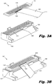
- Fig. 3A is an exploded view of an illustrative die assembly (140) which includes a die carrier (108), adhesive (130), die (105), and a flex cable (120).
- the lower surface (137) of the die carrier (108) is sealed over manifold slots in the backbone (115, Fig. 2 ).
- Oblique tapered channels (150) in the die carrier (108) direct fluid from the lower surface (139) to the upper surface (138) of the die carrier (108).
- the oblique tapered channels (150) have approximately the same pitch and length as the trenches (145) in the die (105).
- the oblique tapered channels (150) direct ink from the manifold slots in the backbone (115, Fig. 2 ) through the die carrier (108) and into the trenches (145).
- the die (105) is adhered to the upper surface (138) with adhesive (130). Because the die carrier (108) is similar in length to the die (105), the die carrier (108) can be molded flat enough to allow the die (105) to be bonded to the die carrier (108) without requiring costly secondary operations. For example, if a 25 millimeter long die requires an upper surface flatness of 0.1 millimeter, the flatness specification is 0.4% of the die carrier length. This is within the capability of precision thermoplastic injection molding without any secondary operations.
- the flex cable (120) is attached to the die contacts (106).
- the electrical conductors in the flex cable (120) are copper ribbons or wires which are covered with gold. These copper ribbons extend beyond the sandwiching polymer films.
- the copper ribbons are attached to the gold plated die contacts (106) using Tape Automated Bonding (TAB).
- TAB Tape Automated Bonding
- a number of additional operations can be performed to ensure that the connection is electrically/mechanically secure and that the flex cable (120) exits the connection at the desired angle.
- the connection may be encapsulated with a curable polymer (i.e. "glob topping").
- a small amount of curable polymer may be deposited under the flex cable (120) and adhere to the underside of the flex cable (120) to the die (105) and/or die carrier (108). An additional quantity of curable polymer is then deposited on top of the connection.
- Fig. 3B is a perspective view of a die assembly (140).
- the die assembly (140) includes the die (105), the die carrier (108), the flex cable (120) and the die connection (124).
- the die assembly (140) is a modular unit which can be independently tested to verify its functionality.
- the die assembly (140) can be electrically tested to verify that the flex cable (120) makes a proper electrical connection with the die (105) through the die connection (124).
- the electrical test may also include checking electrical functions of the die (105).
- the resistance of the various heater elements in the die (105) can be measured by attaching appropriate testing equipment to the opposite end of the flex cable (120).
- the embodiment of the die assembly (140) shown in Fig. 3B has a right facing die carrier (109, Fig. 2 ).
- the die carrier (108) is rotated 180 degrees prior to adhering the die (105) to the upper surface (138, Fig. 3A ) of the die carrier (108).
- the die (105) and flex cable (120) orientation remains the same. This allows the flex cables (120) on both the right and left facing die carriers (108) to come off the same side and simplifies their connection to a single circuit board (125, Fig. 2 ).
- the shroud (110, Fig. 2 ) covers the die carriers (108) and flex cable (120) as much as possible without interfering with the die, electrical connections and flex cable (120).
- the die carriers (108) include a number of features which are configured to interface with and support the shroud (110, Fig. 2 ).
- the support features include posts (135) on either side of the die (105) and corners (137) at either end of the die carrier (108).
- the upper surfaces of these support features (135, 137) are formed in a common plane.
- the die carriers (108) are placed with a significant amount of precision on the backbone (115, Fig. 1 ).
- the die carriers (108) are positioned so that their support features (135, 137) are significantly more coplanar than the backbone (115, Fig. 1 ) which supports them.
- the support features (135, 137) make contact with the under surface of the shroud (110, Fig. 2 ). This provides additional support for the center of the shroud (110, Fig. 2 ) and prevents undesired deflection of the capping surface (16, Fig. 2 ) when the shroud (110, Fig. 2 ) is subjected to wiping or capping forces.
- Fig. 4A is a diagram of an illustrative shroud (110) which is attached to the backbone (115, Fig. 1 ) of the printhead (100, Fig. 1 ).
- the shroud (110) can include a number of features, including a central cutout (118), manufacturing alignment features (400), encapsulation cutouts (410) and perimeter tabs (405).
- the shroud (110) has one continuous cutout (118) which exposes the upper surfaces of all the die (105, Fig. 2 ) when the shroud (110) is in place.
- the manufacturing alignment features may include slots (400-1, 400-3), holes (400-2), pins or other features which would allow for alignment during manufacturing processes.
- the perimeter tab (405) may serve similar purposes during manufacturing or assembly of the printhead (100, Fig. 1 ).
- Fig. 4B is a cut away perspective view of an illustrative shroud (110).
- the shroud (110) includes a cutout (118) in the capping surface (116) and a perimeter flange (112).
- the cutout (118) includes portions which are configured to expose the upper surfaces of the die (105 , Fig. 2 ) and encapsulation cutouts (410) which accommodate the die connections (124 Fig. 2 ).
- the cutout (118) has a rolled edge (121) and a burred edge (119). The rolled edge (121) prevents the wiper, cap or other material from catching on the shroud (110) by eliminating sharp edges and corners.
- the burred edge (119) is less rounded but has been machined to remove sharp protrusions.
- Ramps (122) are angled portions of the side wall. Although the ramps (122) can be at any angle, in this example, the ramps (122) are at approximately a 45 degree angle. The desired angle of the ramps (122) could be determined by a number of factors including the desired stiffness of the shroud (110), wiping design, and other objectives.
- shroud (110) could also be varied from the embodiment shown in Fig. 4B .
- the interior portions of the shroud (110) could be angled downward in order to improve the conformation of the shroud (110) to the die (105, Fig. 2 ).
- shroud (110) could also be used to form a sealing surface around an inline or abutting array of inkjet die. Similar to the staggered die (105, Fig. 2 ), there is insufficient space between the die (105, Fig. 2 ) for a capping surface.
- the shroud (110) could be placed over the inline die (105, Fig. 2 ) array to provide protection and a capping surface.
- the sheet metal shroud (110) has a number of advantages over a plastic injection molded shroud. For example, extending the shroud length to an A3 sized media or larger is easier and less expensive when using a sheet metal shroud. Additionally, the stiffness of the sheet metal shroud can be tuned by simply using thicker metal. In contrast, changing the stiffness of an injection molded part may require the redesign of a mold, creation of additional gussets or ribs. The addition of gussets or ribs to the design can have a detrimental influence on the surface flatness of the plastic injection molded design. The sheet metal shroud does not require any secondary operations to produce a flat surface.
- the sheet metal shroud is supported by the die carriers which have been precision molded and precisely aligned. Further, the sheet metal design is thinner than a plastic injection molded shroud and allows the shroud to be place closer to the die and the flex cable.
- Fig. 5 is a cross sectional diagram showing one illustrative method for sealing the flex cable (120) into indentations (113) in the rail (114).
- a first portion of adhesive sealant (510) is deposited into the rail indentation (113).
- the flex cable (120) is placed into the rail indentation (113) and in contact with the first portion of the adhesive sealant (510).
- the second end of the flex cable (120) can then be connected to the printed circuit board (125, Fig. 2 ).
- a second portion of adhesive sealant (500) is deposited over the portion of the flex cable (120) in the rail indentation (113) and on the rail (114).
- the shroud (110) is then placed so that the underside of a capping surface (116, Fig. 4B ) contacts support features (135, 137, Fig. 3B ) on the die carriers (108) and the perimeter flange (112) of the shroud (110) is sealed over the rail (114) and rail indentations (113).
- the adhesive sealant (500, 510) is then cured while a force is applied which biases the shroud (110) against the support features (135, 137 Fig. 3B ).
- Figs 6A and 6B show illustrative flex cable connections.
- electrical signals and power are supplied to the die (105) from the printed circuit board (125) through flex cables (120).
- These electrical connections represent a significant portion of the printhead (100, Fig. 1 ) assembly cost.
- a single printed circuit board (125) delivers signals and power to each die (105) through individual flex cable (120) connections.
- Fig. 6A shows one illustrative die connection (625) between a flex cable (120) and a die (105).
- conductors (600) extend out of the flex cable (120). These conductors (600) are typically copper with gold plating.
- the conductors (600) are TAB bonded to the specific die contacts (106) on the die (105). After the conductors (600) are connected to contacts (106), a bend is formed in the conductors (600). By bending the conductors (600), the flex cable (120) can exit the connection at the desired direction.
- the electrical conductors (600) are bent such that the flex cable (120) exits the die connection (625) at an acute angle (606) with respect to a side of the die (105). If the conductors (600) were not bent as shown in Fig. 6A , the flex cable (120) itself could be bent to eventually direct the flex cable (120) in the desired direction. However, the radius of curvature of the flex cable (120) bend may be at least one or two orders of magnitude greater than the conductor bend (605).
- Fig. 6B shows the printer circuit board connection (630) at the opposite end of the flex cable (120) where the flex cable (120) connects to the circuit board (125).
- the flex cable (120) is pressed onto a film adhesive (610).
- Wire bonding can then be used to join the flex cable contacts (615) to the circuit board pads (620).
- the wire bonding process is configured to optically match the appropriate flex cable contacts (615) and circuit board pads (620) and make one or more wire bond connections (635) between the appropriate pads (615, 620). Fiduciary features on the pads (615, 620) assist in making the optical identification of the pads (615, 620). Consequently, it is not necessary to precisely locate the flex cable (120) on the film adhesive (610) because the wire bonding process can compensate for small positioning errors.
- Fig. 7 is a cross sectional diagram of a portion of an illustrative printhead assembly (100).
- left facing die carriers (107) and right facing die carriers (109) are attached in a back-to-back configuration on the backbone (115).
- the die carriers (107, 109) include support features (705).
- the die (105) are attached to the die carriers (107, 109).
- the flex cables (120) make electrical connections between the die (105) and the printer circuit board (125, Fig. 6B ).
- the flex cables (120) pass through adhesive sealant (500, 510) in the rail indentations (113).
- the shroud (110) is sealed over the rail (114) and rail indentations (113).
- the cap (700) is placed in contact with the capping surface (116) when the printhead assembly (100) is not in use and creates an enclosed volume (705).
- a small portion of the carrier fluid in the ink evaporates into the enclosed volume (705) and raises the humidity to prevent further evaporation. This prevents undesirable ink solid deposits and increases the operating lifetime of the printhead assembly (100).
- the profile specification of the capping surface (116) may be measured with respect to a number of reference planes, including the upper surfaces of the die (105) or the upper surfaces of the support features (705).
- Fig. 8 is a flowchart of an illustrative method for assembling a wide-array inkjet printhead.
- the method includes biasing a capping surface of a flexible sheet metal shroud against support features of a die carrier such that the surface profile of the capping surface has a surface profile with reduced deviation and meets a target profile specification.
- die assemblies are formed including making an electrical connection between the die and the first end of the flex cables (805).
- the die assemblies are attached to the backbone to form an array of die across the printhead (810).
- a first portion of adhesive sealant is deposited into the rail indentations (815).
- a flexible sheet metal shroud is provided (812).
- the flexible sheet metal shroud has a capping surface with a surface profile that deviates from a reference plane by more than a target deviation.
- a flex cable is placed into the rail indentations and in contact with the first portion of the adhesive sealant (820).
- the flex cable is encapsulated in the rail indentation by applying a second portion of adhesive sealant over the portion of the flex cable in the rail indentation (825).
- This second portion of adhesive sealant is also placed on top of the rail.
- the shroud is placed such that the underside of the capping surface contacts support features on the die assemblies and a perimeter flange of the shroud contacts the second portion of adhesive sealant on the rail and rail indentations (830).
- At least the second portion of the adhesive is cured while applying a force which biases the shroud against the support features on the die carriers (835).
- the surface profile of the capping surface then deviates from the reference plane by no more than a target deviation.
- the first portion of adhesive sealant could be cured previous to the deposition of the second portion of adhesive sealant or it could be cured together with the second portion of adhesive sealant.
- the specification and figures describe a wide-array inkjet printhead which incorporates die carriers covered by a shroud and electrically connected to a circuit board by flex cables.
- the shroud is made from sheet metal and is flexible prior to incorporation onto the printhead.
- the shroud is manufactured to a profile specification which is less stringent than a target profile specification.
- the capping surface has a surface profile with reduced deviation and meets the target profile specification for effective capping of the die.
Claims (15)
- Ensemble tête d'impression (100) à jet d'encre à large réseau pourvu d'une enveloppe souple (110) comprenant :une ossature (115) ;un réseau de matrices (105) dans laquelle les matrices sont montées sur des supports de matrices (108), les matrices (108) étant fixées à l'ossature (115) et comprenant des éléments de soutien (135, 137) ;l'enveloppe (110) comprenant une surface de coiffage (116) pourvue d'un profil de surface qui s'écarte d'un plan de référence de plus d'un écart cible avant une transposition de l'enveloppe sur la tête d'impression ;dans lequel les éléments de soutien (135, 137) interfacent avec et soutiennent une surface inférieure de l'enveloppe (110) de telle sorte que la surface de coiffage (116) de l'enveloppe (110), lorsqu'elle est sollicitée contre les éléments de soutien (135, 137), s'écarte du plan de référence dans une limite de l'écart cible.
- Ensemble tête d'impression (100) selon la revendication 1, dans lequel l'ossature (115) comprend un rail (114) qui entoure le réseau de matrices (105), et l'enveloppe (110) comprend en outre une bride (112) formée autour d'un périmètre de l'enveloppe (110), dans lequel la bride (112) est liée au rail (114) de telle sorte que lorsqu'une coiffe (700) est mise en contact avec la surface de coiffage (116), un volume enfermé (705) est formé qui contient les matrices (105).
- Ensemble tête d'impression (100) selon la revendication 2, comprenant en outre :une carte de circuit imprimé (125) ; etdes câbles souples (120) qui connectent individuellement chacune des matrices (105) à la carte de circuit imprimé (125), chacun des câbles souples (120) présentant une connexion de matrices (124) et une connexion de carte de circuit imprimé (122).
- Ensemble tête d'impression (100) selon la revendication 3, dans lequel le rail (114) comprend en outre des indentations (113), les câbles souples (120) passant à travers les indentations, les indentations étant remplies de matériau d'étanchéité adhésif (500, 510) afin de former un joint d'étanchéité autour des câbles souples (120) et avec la bride (112).
- Ensemble tête d'impression (100) selon la revendication 3, dans lequel l'enveloppe (110) comprend en outre une découpe (118) dans l'enveloppe, les surfaces supérieures des matrices étant exposées à travers la découpe.
- Ensemble tête d'impression (100) selon la revendication 3, dans lequel la connexion de matrices (124) comprend :
des conducteurs électriques (600) s'étendant à partir d'une première extrémité du câble souple (120), les conducteurs électriques étant liés à des contacts de matrices (106) sur les matrices (105). - Ensemble tête d'impression (100) selon la revendication 6, dans lequel les conducteurs électriques (600) sont courbés de telle sorte que le câble souple (120) sort de la connexion de matrices (124) à un angle aigu (606) par rapport à un côté des matrices (105), la connexion de matrices (124) comprenant en outre un matériau d'étanchéité adhésif (500, 510) soutenant et encapsulant les contacts de matrices (106), les conducteurs électriques (600) et la première extrémité du câble souple (120).
- Ensemble tête d'impression (100) selon la revendication 3, dans lequel la connexion de carte de circuit imprimé (630) comprend :une carte de circuit imprimé (125) comprenant des pastilles de carte de circuit imprimé (620) ;un film adhésif (610) adhéré à la carte de circuit imprimé (125) ;une seconde extrémité du câble souple (120) présentant des contacts de câble souple (615) et étant pressée sur le film adhésif (610) ; etdes liaisons de fils (635) qui sont formées entre les contacts de câbles souples (615) et les pastille de carte de circuit imprimé (620) de telle sorte que les liaisons de fils (635) compensent le désalignement entre les contacts de câbles souples (615) et les pastilles de carte de circuit imprimé (620).
- Ensemble tête d'impression (100) selon la revendication 5, dans lequel les supports de matrices (108) sont en quinconce dos à dos sur une partie substantielle de l'ossature (115), la découpe (118) dans l'enveloppe (110) exposant les surface supérieures de chacune des matrices (105).
- Ensemble tête d'impression (100) selon la revendication 5, dans lequel la découpe (118) comprend une découpe d'encapsulation (410) qui reçoit la connexion de matrices (124).
- Ensemble tête d'impression (100) selon la revendication 2, dans lequel l'enveloppe (110) est fixée à l'ossature (115) de telle sorte que la surface de coiffage (116) de l'enveloppe (110) est sollicitée contre les éléments de soutien (135, 137) par une liaison adhésive entre la bride (112) et le rail (114).
- Ensemble tête d'impression (100) selon la revendication 1, dans lequel l'enveloppe (110) est formée de tôle présentant une épaisseur qui est inférieure à 0,5 millimètre.
- Ensemble tête d'impression (100) selon la revendication 1, dans lequel l'enveloppe (110) est formée de tôle d'acier inoxydable présentant une épaisseur d'environ 0,25 millimètre.
- Ensemble tête d'impression (100) selon la revendication 1, dans lequel le réseau de matrices (105) est un réseau en quinconce dos à dos de matrices à jet d'encre, et dans lequel l'enveloppe (110) comprend :une bride (112) autour du périmètre de l'enveloppe (110) pour assurer l'étanchéité avec un rail (114) sur l'ossature (115) ;une découpe (118) pour exposer le réseau de matrices (105) à jet d'encre, les matrices à jet d'encre étant disposées sur des supports de matrices (108) présentant des éléments de soutien (135, 137) ; etune surface de coiffage (116) pour interfacer avec une coiffe (700), le dessous de la surface de coiffage étant sollicitée contre les éléments de soutien (135, 137) des supports de matrices (108) afin d'obtenir une spécification de profil inférieure à 0,2 % ;dans lequel l'enveloppe (110) est formée d'acier inoxydable d'une épaisseur inférieure à 0,5 millimètre et est fabriquée selon une spécification de profil supérieure à 0,2 % ;dans lequel la spécification de profil définit une exigence selon laquelle tous les points sur la surface de coiffage (116) doivent se trouver entre deux plans qui sont à des emplacements spécifiés par rapport à un plan de référence et à une distance spécifiée l'un de l'autre.
- Procédé d'assemblage d'un ensemble tête d'impression à jet d'encre à large réseau (100) comprenant :la fixation d'ensembles matrices (140) à une ossature (115) afin de former un réseau de matrices (105) à travers la tête d'impression ;la fourniture d'une enveloppe en tôle souple (110) présentant une surface de coiffage (116) pourvue d'un profil de surface qui s'écarte d'un plan de référence de plus d'un écart cible, dans lequel l'enveloppe (110) est placée de telle sorte que le dessous de la surface de coiffage (116) entre en contact avec des éléments de soutien (135, 137) sur les ensembles matrice (140) ; etla sollicitation de la surface de coiffage (116) de l'enveloppe souple en tôle (110) contre des éléments de soutien (135, 137) de telle sorte que le profil de surface de la surface de coiffage (116) s'écarte du plan de référence dans la limite de l'écart cible, dans laquelle les éléments de soutien (135, 137) interfacent avec et soutiennent une surface inférieure de l'enveloppe (110) de telle sorte que la surface de coiffage (116) de l'enveloppe (110), lorsqu'elle est sollicitée contre les éléments de soutien (135, 137), s'écarte du plan de référence dans la limite de l'écart cible.
Applications Claiming Priority (1)
| Application Number | Priority Date | Filing Date | Title |
|---|---|---|---|
| PCT/US2010/045978 WO2012023939A1 (fr) | 2010-08-19 | 2010-08-19 | Ensemble tête d'impression à jet d'encre à groupement large comportant un écran |
Publications (3)
| Publication Number | Publication Date |
|---|---|
| EP2605910A1 EP2605910A1 (fr) | 2013-06-26 |
| EP2605910A4 EP2605910A4 (fr) | 2018-02-21 |
| EP2605910B1 true EP2605910B1 (fr) | 2020-10-21 |
Family
ID=45605372
Family Applications (1)
| Application Number | Title | Priority Date | Filing Date |
|---|---|---|---|
| EP10856239.8A Active EP2605910B1 (fr) | 2010-08-19 | 2010-08-19 | Ensemble tête d'impression à jet d'encre à groupement large comportant un écran |
Country Status (4)
| Country | Link |
|---|---|
| US (1) | US8702200B2 (fr) |
| EP (1) | EP2605910B1 (fr) |
| CN (1) | CN103052507B (fr) |
| WO (1) | WO2012023939A1 (fr) |
Families Citing this family (21)
| Publication number | Priority date | Publication date | Assignee | Title |
|---|---|---|---|---|
| DK2825386T3 (en) | 2013-02-28 | 2018-04-16 | Hewlett Packard Development Co | CASTED FLUID FLOW STRUCTURE |
| US9517626B2 (en) | 2013-02-28 | 2016-12-13 | Hewlett-Packard Development Company, L.P. | Printed circuit board fluid ejection apparatus |
| WO2014133561A1 (fr) | 2013-02-28 | 2014-09-04 | Hewlett-Packard Development Company, L.P. | Moulage d'une structure d'écoulement de fluide |
| CN107901609B (zh) | 2013-02-28 | 2020-08-28 | 惠普发展公司,有限责任合伙企业 | 流体流动结构和打印头 |
| US9724920B2 (en) | 2013-03-20 | 2017-08-08 | Hewlett-Packard Development Company, L.P. | Molded die slivers with exposed front and back surfaces |
| WO2015163862A1 (fr) | 2014-04-23 | 2015-10-29 | Hewlett-Packard Development Company, L.P. | Ensemble de têtes d'impression |
| JP6422366B2 (ja) | 2014-05-13 | 2018-11-14 | キヤノン株式会社 | 液体吐出ヘッド及び記録装置 |
| EP3148812B1 (fr) | 2014-05-30 | 2020-12-23 | Hewlett-Packard Development Company, L.P. | Enveloppe pour un module d'assemblage de tête d'impression et module d'assemblage de tête d'impression |
| US10272680B2 (en) | 2015-05-15 | 2019-04-30 | Hewlett-Packard Development Company, L.P. | Fluid ejection device |
| CN107531051B (zh) | 2015-10-26 | 2019-12-20 | 惠普发展公司,有限责任合伙企业 | 打印头和制造打印头的方法 |
| JP6843501B2 (ja) * | 2015-11-12 | 2021-03-17 | キヤノン株式会社 | 検査方法 |
| JP6750855B2 (ja) * | 2016-05-27 | 2020-09-02 | キヤノン株式会社 | 液体吐出ヘッドおよび液体吐出装置 |
| JP6921667B2 (ja) | 2017-07-12 | 2021-08-18 | キヤノン株式会社 | 液体吐出ヘッド、液体吐出装置 |
| WO2019089023A1 (fr) * | 2017-11-01 | 2019-05-09 | Hewlett-Packard Development Company, L.P. | Ensemble support de cible d'impression |
| JP7026486B2 (ja) * | 2017-11-07 | 2022-02-28 | エスアイアイ・プリンテック株式会社 | 液体噴射ヘッドおよび液体噴射記録装置 |
| JP7102905B2 (ja) * | 2018-04-26 | 2022-07-20 | ブラザー工業株式会社 | 記録装置及び配線部材 |
| JP7091824B2 (ja) * | 2018-05-18 | 2022-06-28 | セイコーエプソン株式会社 | ケーブル群及びケーブル |
| JP7182943B2 (ja) | 2018-08-07 | 2022-12-05 | キヤノン株式会社 | 液体吐出ヘッド及び記録装置 |
| US11358390B2 (en) | 2018-09-27 | 2022-06-14 | Hewlett-Packard Development Company, L.P. | Carriers including fluid ejection dies |
| WO2020101659A1 (fr) | 2018-11-14 | 2020-05-22 | Hewlett-Packard Development Company, L.P. | Ensembles puces fluidiques avec des substrats coudés rigides |
| JP7288073B2 (ja) * | 2019-10-31 | 2023-06-06 | 京セラ株式会社 | 液滴吐出ヘッド及び記録装置 |
Family Cites Families (21)
| Publication number | Priority date | Publication date | Assignee | Title |
|---|---|---|---|---|
| IT1144294B (it) * | 1981-07-10 | 1986-10-29 | Olivetti & Co Spa | Dispositivo di stampa getto selettivo d inchiostro |
| IT1182285B (it) * | 1984-09-25 | 1987-10-05 | Olivetti & Co Spa | Testina di stampa a getto d inchiostro relativo procedimento di fabbricazione ed attrezzo utilizzabile per l attuazione di tale procedimento |
| JPH0939244A (ja) * | 1995-05-23 | 1997-02-10 | Fujitsu Ltd | 圧電ポンプ |
| US6471330B1 (en) | 1999-09-16 | 2002-10-29 | Brother Kogyo Kabushiki Kaisha | Maintenance cap forming a sealed condition around nozzle rows of an ink jet print head |
| SG136001A1 (en) * | 2000-08-09 | 2007-10-29 | Sony Corp | Print head, manufacturing method therefor, and printer |
| US6648452B2 (en) | 2000-10-31 | 2003-11-18 | Brother Kogyo Kabushiki Kaisha | Manifold plate of ink jet head |
| JP2002144575A (ja) * | 2000-11-17 | 2002-05-21 | Canon Inc | 液体噴射ヘッドおよび液体噴射装置 |
| US6679595B2 (en) | 2001-02-08 | 2004-01-20 | Brother Kogyo Kabushiki Kaisha | Ink jet recording apparatus |
| US6626518B2 (en) * | 2001-10-25 | 2003-09-30 | Hewlett-Packard Development Company, L.P. | Bending a tab flex circuit via cantilevered leads |
| US7295279B2 (en) * | 2002-06-28 | 2007-11-13 | Lg.Philips Lcd Co., Ltd. | System and method for manufacturing liquid crystal display devices |
| US6722756B2 (en) | 2002-07-01 | 2004-04-20 | Hewlett-Packard Development Company, L.P. | Capping shroud for fluid ejection device |
| US7188925B2 (en) | 2004-01-30 | 2007-03-13 | Hewlett-Packard Development Company, L.P. | Fluid ejection head assembly |
| US7240991B2 (en) | 2004-03-09 | 2007-07-10 | Hewlett-Packard Development Company, L.P. | Fluid ejection device and manufacturing method |
| US20050219327A1 (en) * | 2004-03-31 | 2005-10-06 | Clarke Leo C | Features in substrates and methods of forming |
| KR100624443B1 (ko) * | 2004-11-04 | 2006-09-15 | 삼성전자주식회사 | 일방향 셔터를 구비한 압전 방식의 잉크젯 프린트헤드 |
| JP4728633B2 (ja) * | 2004-12-03 | 2011-07-20 | 株式会社東芝 | インクジェット塗布装置 |
| US7293853B2 (en) | 2004-12-06 | 2007-11-13 | Silverbrook Research Pty Ltd | Inkjet printer with simplex printhead and capping mechanism |
| KR101402084B1 (ko) | 2007-01-16 | 2014-06-09 | 삼성전자주식회사 | 잉크 공급유닛과 프린트헤드 조립체 및 화상형성장치 |
| KR20080068260A (ko) * | 2007-01-18 | 2008-07-23 | 삼성전자주식회사 | 잉크젯 프린터 및 잉크젯 프린터 헤드칩 조립체 |
| KR101168990B1 (ko) | 2007-06-27 | 2012-08-09 | 삼성전자주식회사 | 어레이 잉크젯헤드 및 이를 구비하는 잉크젯 화상형성장치 |
| KR20100027812A (ko) * | 2008-09-03 | 2010-03-11 | 삼성전자주식회사 | 어레이 타입 잉크젯 인쇄 헤드, 및 이를 구비한 화상형성장치 |
-
2010
- 2010-08-19 WO PCT/US2010/045978 patent/WO2012023939A1/fr active Application Filing
- 2010-08-19 EP EP10856239.8A patent/EP2605910B1/fr active Active
- 2010-08-19 CN CN201080068651.4A patent/CN103052507B/zh not_active Expired - Fee Related
- 2010-08-19 US US13/703,171 patent/US8702200B2/en active Active
Non-Patent Citations (1)
| Title |
|---|
| None * |
Also Published As
| Publication number | Publication date |
|---|---|
| US20130083120A1 (en) | 2013-04-04 |
| EP2605910A1 (fr) | 2013-06-26 |
| US8702200B2 (en) | 2014-04-22 |
| CN103052507B (zh) | 2015-01-07 |
| CN103052507A (zh) | 2013-04-17 |
| EP2605910A4 (fr) | 2018-02-21 |
| WO2012023939A1 (fr) | 2012-02-23 |
Similar Documents
| Publication | Publication Date | Title |
|---|---|---|
| EP2605910B1 (fr) | Ensemble tête d'impression à jet d'encre à groupement large comportant un écran | |
| EP2605911B1 (fr) | Ensemble de tête d'impression jet d'encre à réseau large | |
| US6684503B1 (en) | Method of manufacturing a four color modular printhead | |
| EP0624472B1 (fr) | Tête à jet d'encre | |
| CN1966269B (zh) | 具有由可弯曲通道保持的打印头模块的打印头组件 | |
| US20070165077A1 (en) | Head module, liquid jetting head, liquid jetting apparatus, method of manufacturing head module, and method of manufacturing liquid jetting head | |
| JP5175970B2 (ja) | プリントヘッドモジュール | |
| US10596817B2 (en) | Liquid ejecting head unit and liquid ejecting apparatus | |
| AU2004200363B2 (en) | An ink supply device for a four color modular printhead | |
| AU2004200368B2 (en) | Modular Inkjet Printhead Assembly | |
| AU2005200944B2 (en) | Printhead Assembly Having Two-Shot Ink Supply Molding |
Legal Events
| Date | Code | Title | Description |
|---|---|---|---|
| PUAI | Public reference made under article 153(3) epc to a published international application that has entered the european phase |
Free format text: ORIGINAL CODE: 0009012 |
|
| 17P | Request for examination filed |
Effective date: 20130207 |
|
| AK | Designated contracting states |
Kind code of ref document: A1 Designated state(s): AL AT BE BG CH CY CZ DE DK EE ES FI FR GB GR HR HU IE IS IT LI LT LU LV MC MK MT NL NO PL PT RO SE SI SK SM TR |
|
| DAX | Request for extension of the european patent (deleted) | ||
| RA4 | Supplementary search report drawn up and despatched (corrected) |
Effective date: 20180123 |
|
| RIC1 | Information provided on ipc code assigned before grant |
Ipc: B41J 2/175 20060101AFI20180117BHEP Ipc: B41J 2/155 20060101ALI20180117BHEP Ipc: B41J 2/14 20060101ALI20180117BHEP Ipc: B41J 2/165 20060101ALI20180117BHEP |
|
| STAA | Information on the status of an ep patent application or granted ep patent |
Free format text: STATUS: EXAMINATION IS IN PROGRESS |
|
| RAP1 | Party data changed (applicant data changed or rights of an application transferred) |
Owner name: HEWLETT-PACKARD DEVELOPMENT COMPANY, L.P. |
|
| 17Q | First examination report despatched |
Effective date: 20190417 |
|
| GRAP | Despatch of communication of intention to grant a patent |
Free format text: ORIGINAL CODE: EPIDOSNIGR1 |
|
| STAA | Information on the status of an ep patent application or granted ep patent |
Free format text: STATUS: GRANT OF PATENT IS INTENDED |
|
| INTG | Intention to grant announced |
Effective date: 20200619 |
|
| GRAS | Grant fee paid |
Free format text: ORIGINAL CODE: EPIDOSNIGR3 |
|
| GRAA | (expected) grant |
Free format text: ORIGINAL CODE: 0009210 |
|
| STAA | Information on the status of an ep patent application or granted ep patent |
Free format text: STATUS: THE PATENT HAS BEEN GRANTED |
|
| AK | Designated contracting states |
Kind code of ref document: B1 Designated state(s): AL AT BE BG CH CY CZ DE DK EE ES FI FR GB GR HR HU IE IS IT LI LT LU LV MC MK MT NL NO PL PT RO SE SI SK SM TR |
|
| REG | Reference to a national code |
Ref country code: GB Ref legal event code: FG4D |
|
| REG | Reference to a national code |
Ref country code: CH Ref legal event code: EP |
|
| REG | Reference to a national code |
Ref country code: IE Ref legal event code: FG4D |
|
| REG | Reference to a national code |
Ref country code: DE Ref legal event code: R096 Ref document number: 602010065747 Country of ref document: DE |
|
| REG | Reference to a national code |
Ref country code: AT Ref legal event code: REF Ref document number: 1325440 Country of ref document: AT Kind code of ref document: T Effective date: 20201115 |
|
| REG | Reference to a national code |
Ref country code: AT Ref legal event code: MK05 Ref document number: 1325440 Country of ref document: AT Kind code of ref document: T Effective date: 20201021 |
|
| REG | Reference to a national code |
Ref country code: NL Ref legal event code: MP Effective date: 20201021 |
|
| PG25 | Lapsed in a contracting state [announced via postgrant information from national office to epo] |
Ref country code: FI Free format text: LAPSE BECAUSE OF FAILURE TO SUBMIT A TRANSLATION OF THE DESCRIPTION OR TO PAY THE FEE WITHIN THE PRESCRIBED TIME-LIMIT Effective date: 20201021 Ref country code: PT Free format text: LAPSE BECAUSE OF FAILURE TO SUBMIT A TRANSLATION OF THE DESCRIPTION OR TO PAY THE FEE WITHIN THE PRESCRIBED TIME-LIMIT Effective date: 20210222 Ref country code: NL Free format text: LAPSE BECAUSE OF FAILURE TO SUBMIT A TRANSLATION OF THE DESCRIPTION OR TO PAY THE FEE WITHIN THE PRESCRIBED TIME-LIMIT Effective date: 20201021 Ref country code: NO Free format text: LAPSE BECAUSE OF FAILURE TO SUBMIT A TRANSLATION OF THE DESCRIPTION OR TO PAY THE FEE WITHIN THE PRESCRIBED TIME-LIMIT Effective date: 20210121 Ref country code: GR Free format text: LAPSE BECAUSE OF FAILURE TO SUBMIT A TRANSLATION OF THE DESCRIPTION OR TO PAY THE FEE WITHIN THE PRESCRIBED TIME-LIMIT Effective date: 20210122 |
|
| REG | Reference to a national code |
Ref country code: LT Ref legal event code: MG4D |
|
| PG25 | Lapsed in a contracting state [announced via postgrant information from national office to epo] |
Ref country code: ES Free format text: LAPSE BECAUSE OF FAILURE TO SUBMIT A TRANSLATION OF THE DESCRIPTION OR TO PAY THE FEE WITHIN THE PRESCRIBED TIME-LIMIT Effective date: 20201021 Ref country code: IS Free format text: LAPSE BECAUSE OF FAILURE TO SUBMIT A TRANSLATION OF THE DESCRIPTION OR TO PAY THE FEE WITHIN THE PRESCRIBED TIME-LIMIT Effective date: 20210221 Ref country code: AT Free format text: LAPSE BECAUSE OF FAILURE TO SUBMIT A TRANSLATION OF THE DESCRIPTION OR TO PAY THE FEE WITHIN THE PRESCRIBED TIME-LIMIT Effective date: 20201021 Ref country code: BG Free format text: LAPSE BECAUSE OF FAILURE TO SUBMIT A TRANSLATION OF THE DESCRIPTION OR TO PAY THE FEE WITHIN THE PRESCRIBED TIME-LIMIT Effective date: 20210121 Ref country code: SE Free format text: LAPSE BECAUSE OF FAILURE TO SUBMIT A TRANSLATION OF THE DESCRIPTION OR TO PAY THE FEE WITHIN THE PRESCRIBED TIME-LIMIT Effective date: 20201021 Ref country code: LV Free format text: LAPSE BECAUSE OF FAILURE TO SUBMIT A TRANSLATION OF THE DESCRIPTION OR TO PAY THE FEE WITHIN THE PRESCRIBED TIME-LIMIT Effective date: 20201021 Ref country code: PL Free format text: LAPSE BECAUSE OF FAILURE TO SUBMIT A TRANSLATION OF THE DESCRIPTION OR TO PAY THE FEE WITHIN THE PRESCRIBED TIME-LIMIT Effective date: 20201021 |
|
| PG25 | Lapsed in a contracting state [announced via postgrant information from national office to epo] |
Ref country code: HR Free format text: LAPSE BECAUSE OF FAILURE TO SUBMIT A TRANSLATION OF THE DESCRIPTION OR TO PAY THE FEE WITHIN THE PRESCRIBED TIME-LIMIT Effective date: 20201021 |
|
| REG | Reference to a national code |
Ref country code: DE Ref legal event code: R097 Ref document number: 602010065747 Country of ref document: DE |
|
| PG25 | Lapsed in a contracting state [announced via postgrant information from national office to epo] |
Ref country code: LT Free format text: LAPSE BECAUSE OF FAILURE TO SUBMIT A TRANSLATION OF THE DESCRIPTION OR TO PAY THE FEE WITHIN THE PRESCRIBED TIME-LIMIT Effective date: 20201021 Ref country code: SK Free format text: LAPSE BECAUSE OF FAILURE TO SUBMIT A TRANSLATION OF THE DESCRIPTION OR TO PAY THE FEE WITHIN THE PRESCRIBED TIME-LIMIT Effective date: 20201021 Ref country code: RO Free format text: LAPSE BECAUSE OF FAILURE TO SUBMIT A TRANSLATION OF THE DESCRIPTION OR TO PAY THE FEE WITHIN THE PRESCRIBED TIME-LIMIT Effective date: 20201021 Ref country code: SM Free format text: LAPSE BECAUSE OF FAILURE TO SUBMIT A TRANSLATION OF THE DESCRIPTION OR TO PAY THE FEE WITHIN THE PRESCRIBED TIME-LIMIT Effective date: 20201021 Ref country code: EE Free format text: LAPSE BECAUSE OF FAILURE TO SUBMIT A TRANSLATION OF THE DESCRIPTION OR TO PAY THE FEE WITHIN THE PRESCRIBED TIME-LIMIT Effective date: 20201021 Ref country code: CZ Free format text: LAPSE BECAUSE OF FAILURE TO SUBMIT A TRANSLATION OF THE DESCRIPTION OR TO PAY THE FEE WITHIN THE PRESCRIBED TIME-LIMIT Effective date: 20201021 |
|
| PLBE | No opposition filed within time limit |
Free format text: ORIGINAL CODE: 0009261 |
|
| STAA | Information on the status of an ep patent application or granted ep patent |
Free format text: STATUS: NO OPPOSITION FILED WITHIN TIME LIMIT |
|
| PG25 | Lapsed in a contracting state [announced via postgrant information from national office to epo] |
Ref country code: DK Free format text: LAPSE BECAUSE OF FAILURE TO SUBMIT A TRANSLATION OF THE DESCRIPTION OR TO PAY THE FEE WITHIN THE PRESCRIBED TIME-LIMIT Effective date: 20201021 |
|
| 26N | No opposition filed |
Effective date: 20210722 |
|
| PG25 | Lapsed in a contracting state [announced via postgrant information from national office to epo] |
Ref country code: AL Free format text: LAPSE BECAUSE OF FAILURE TO SUBMIT A TRANSLATION OF THE DESCRIPTION OR TO PAY THE FEE WITHIN THE PRESCRIBED TIME-LIMIT Effective date: 20201021 Ref country code: IT Free format text: LAPSE BECAUSE OF FAILURE TO SUBMIT A TRANSLATION OF THE DESCRIPTION OR TO PAY THE FEE WITHIN THE PRESCRIBED TIME-LIMIT Effective date: 20201021 |
|
| PGFP | Annual fee paid to national office [announced via postgrant information from national office to epo] |
Ref country code: FR Payment date: 20210722 Year of fee payment: 12 |
|
| PG25 | Lapsed in a contracting state [announced via postgrant information from national office to epo] |
Ref country code: SI Free format text: LAPSE BECAUSE OF FAILURE TO SUBMIT A TRANSLATION OF THE DESCRIPTION OR TO PAY THE FEE WITHIN THE PRESCRIBED TIME-LIMIT Effective date: 20201021 |
|
| PGFP | Annual fee paid to national office [announced via postgrant information from national office to epo] |
Ref country code: DE Payment date: 20210720 Year of fee payment: 12 Ref country code: GB Payment date: 20210720 Year of fee payment: 12 |
|
| REG | Reference to a national code |
Ref country code: CH Ref legal event code: PL |
|
| PG25 | Lapsed in a contracting state [announced via postgrant information from national office to epo] |
Ref country code: MC Free format text: LAPSE BECAUSE OF FAILURE TO SUBMIT A TRANSLATION OF THE DESCRIPTION OR TO PAY THE FEE WITHIN THE PRESCRIBED TIME-LIMIT Effective date: 20201021 |
|
| REG | Reference to a national code |
Ref country code: BE Ref legal event code: MM Effective date: 20210831 |
|
| PG25 | Lapsed in a contracting state [announced via postgrant information from national office to epo] |
Ref country code: LI Free format text: LAPSE BECAUSE OF NON-PAYMENT OF DUE FEES Effective date: 20210831 Ref country code: CH Free format text: LAPSE BECAUSE OF NON-PAYMENT OF DUE FEES Effective date: 20210831 |
|
| PG25 | Lapsed in a contracting state [announced via postgrant information from national office to epo] |
Ref country code: IS Free format text: LAPSE BECAUSE OF FAILURE TO SUBMIT A TRANSLATION OF THE DESCRIPTION OR TO PAY THE FEE WITHIN THE PRESCRIBED TIME-LIMIT Effective date: 20210221 Ref country code: LU Free format text: LAPSE BECAUSE OF NON-PAYMENT OF DUE FEES Effective date: 20210819 |
|
| PG25 | Lapsed in a contracting state [announced via postgrant information from national office to epo] |
Ref country code: IE Free format text: LAPSE BECAUSE OF NON-PAYMENT OF DUE FEES Effective date: 20210819 Ref country code: BE Free format text: LAPSE BECAUSE OF NON-PAYMENT OF DUE FEES Effective date: 20210831 |
|
| REG | Reference to a national code |
Ref country code: DE Ref legal event code: R119 Ref document number: 602010065747 Country of ref document: DE |
|
| GBPC | Gb: european patent ceased through non-payment of renewal fee |
Effective date: 20220819 |
|
| PG25 | Lapsed in a contracting state [announced via postgrant information from national office to epo] |
Ref country code: HU Free format text: LAPSE BECAUSE OF FAILURE TO SUBMIT A TRANSLATION OF THE DESCRIPTION OR TO PAY THE FEE WITHIN THE PRESCRIBED TIME-LIMIT; INVALID AB INITIO Effective date: 20100819 Ref country code: CY Free format text: LAPSE BECAUSE OF FAILURE TO SUBMIT A TRANSLATION OF THE DESCRIPTION OR TO PAY THE FEE WITHIN THE PRESCRIBED TIME-LIMIT Effective date: 20201021 |
|
| PG25 | Lapsed in a contracting state [announced via postgrant information from national office to epo] |
Ref country code: FR Free format text: LAPSE BECAUSE OF NON-PAYMENT OF DUE FEES Effective date: 20220831 Ref country code: DE Free format text: LAPSE BECAUSE OF NON-PAYMENT OF DUE FEES Effective date: 20230301 |
|
| PG25 | Lapsed in a contracting state [announced via postgrant information from national office to epo] |
Ref country code: GB Free format text: LAPSE BECAUSE OF NON-PAYMENT OF DUE FEES Effective date: 20220819 |