EP2603626B9 - Process and apparatus for spinning fibres and in particular for producing a fibrous-containing nonwoven - Google Patents
Process and apparatus for spinning fibres and in particular for producing a fibrous-containing nonwoven Download PDFInfo
- Publication number
- EP2603626B9 EP2603626B9 EP11743819.2A EP11743819A EP2603626B9 EP 2603626 B9 EP2603626 B9 EP 2603626B9 EP 11743819 A EP11743819 A EP 11743819A EP 2603626 B9 EP2603626 B9 EP 2603626B9
- Authority
- EP
- European Patent Office
- Prior art keywords
- filaments
- die head
- fibres
- drawing unit
- meltblown
- Prior art date
- Legal status (The legal status is an assumption and is not a legal conclusion. Google has not performed a legal analysis and makes no representation as to the accuracy of the status listed.)
- Active
Links
- 238000009987 spinning Methods 0.000 title claims description 39
- 238000000034 method Methods 0.000 title claims description 36
- 239000002657 fibrous material Substances 0.000 claims description 58
- 229920000642 polymer Polymers 0.000 claims description 16
- 238000007664 blowing Methods 0.000 claims description 14
- 239000000463 material Substances 0.000 claims description 14
- 238000001816 cooling Methods 0.000 claims description 11
- 238000010791 quenching Methods 0.000 claims description 7
- 230000002745 absorbent Effects 0.000 claims description 6
- 239000002250 absorbent Substances 0.000 claims description 6
- 230000000171 quenching effect Effects 0.000 claims description 6
- 239000000155 melt Substances 0.000 claims description 4
- 206010021639 Incontinence Diseases 0.000 claims description 3
- 230000002238 attenuated effect Effects 0.000 claims description 2
- 239000004750 melt-blown nonwoven Substances 0.000 description 26
- 238000004519 manufacturing process Methods 0.000 description 7
- 229920001131 Pulp (paper) Polymers 0.000 description 6
- 229920001577 copolymer Polymers 0.000 description 5
- 238000005516 engineering process Methods 0.000 description 5
- 229920001519 homopolymer Polymers 0.000 description 5
- 239000002245 particle Substances 0.000 description 5
- 239000000203 mixture Substances 0.000 description 4
- 238000003860 storage Methods 0.000 description 4
- 241000196324 Embryophyta Species 0.000 description 3
- 238000007596 consolidation process Methods 0.000 description 3
- 238000005520 cutting process Methods 0.000 description 3
- 230000001627 detrimental effect Effects 0.000 description 3
- 238000001125 extrusion Methods 0.000 description 3
- 239000008188 pellet Substances 0.000 description 3
- -1 polypropylene Polymers 0.000 description 3
- 229920000742 Cotton Polymers 0.000 description 2
- 239000004743 Polypropylene Substances 0.000 description 2
- 238000004026 adhesive bonding Methods 0.000 description 2
- MJBPUQUGJNAPAZ-AWEZNQCLSA-N butin Chemical compound C1([C@@H]2CC(=O)C3=CC=C(C=C3O2)O)=CC=C(O)C(O)=C1 MJBPUQUGJNAPAZ-AWEZNQCLSA-N 0.000 description 2
- 239000000835 fiber Substances 0.000 description 2
- 239000002985 plastic film Substances 0.000 description 2
- 229920006255 plastic film Polymers 0.000 description 2
- 239000004626 polylactic acid Substances 0.000 description 2
- 229920001155 polypropylene Polymers 0.000 description 2
- 238000007711 solidification Methods 0.000 description 2
- 230000008023 solidification Effects 0.000 description 2
- 239000004753 textile Substances 0.000 description 2
- 229920001169 thermoplastic Polymers 0.000 description 2
- 241000609240 Ambelania acida Species 0.000 description 1
- MJBPUQUGJNAPAZ-UHFFFAOYSA-N Butine Natural products O1C2=CC(O)=CC=C2C(=O)CC1C1=CC=C(O)C(O)=C1 MJBPUQUGJNAPAZ-UHFFFAOYSA-N 0.000 description 1
- 244000025254 Cannabis sativa Species 0.000 description 1
- 235000012766 Cannabis sativa ssp. sativa var. sativa Nutrition 0.000 description 1
- 235000012765 Cannabis sativa ssp. sativa var. spontanea Nutrition 0.000 description 1
- 240000000491 Corchorus aestuans Species 0.000 description 1
- 235000011777 Corchorus aestuans Nutrition 0.000 description 1
- 235000010862 Corchorus capsularis Nutrition 0.000 description 1
- 244000207543 Euphorbia heterophylla Species 0.000 description 1
- 241000219146 Gossypium Species 0.000 description 1
- 240000006240 Linum usitatissimum Species 0.000 description 1
- 235000004431 Linum usitatissimum Nutrition 0.000 description 1
- 241001148717 Lygeum spartum Species 0.000 description 1
- 229920001410 Microfiber Polymers 0.000 description 1
- 239000004952 Polyamide Substances 0.000 description 1
- 239000004698 Polyethylene Substances 0.000 description 1
- 229910000831 Steel Inorganic materials 0.000 description 1
- 239000010905 bagasse Substances 0.000 description 1
- 235000009120 camo Nutrition 0.000 description 1
- 235000005607 chanvre indien Nutrition 0.000 description 1
- 230000006835 compression Effects 0.000 description 1
- 238000007906 compression Methods 0.000 description 1
- 238000010924 continuous production Methods 0.000 description 1
- 230000000694 effects Effects 0.000 description 1
- 229920001971 elastomer Polymers 0.000 description 1
- 230000005484 gravity Effects 0.000 description 1
- 238000010438 heat treatment Methods 0.000 description 1
- 239000011487 hemp Substances 0.000 description 1
- 239000003658 microfiber Substances 0.000 description 1
- 235000001954 papillon Nutrition 0.000 description 1
- 244000229285 papillon Species 0.000 description 1
- 230000035699 permeability Effects 0.000 description 1
- 229920000747 poly(lactic acid) Polymers 0.000 description 1
- 229920002647 polyamide Polymers 0.000 description 1
- 229920000728 polyester Polymers 0.000 description 1
- 229920000573 polyethylene Polymers 0.000 description 1
- 229920000098 polyolefin Polymers 0.000 description 1
- 239000005060 rubber Substances 0.000 description 1
- 239000010959 steel Substances 0.000 description 1
- 239000010902 straw Substances 0.000 description 1
- 239000004416 thermosoftening plastic Substances 0.000 description 1
- 238000011144 upstream manufacturing Methods 0.000 description 1
- XLYOFNOQVPJJNP-UHFFFAOYSA-N water Substances O XLYOFNOQVPJJNP-UHFFFAOYSA-N 0.000 description 1
Images


Classifications
-
- D—TEXTILES; PAPER
- D01—NATURAL OR MAN-MADE THREADS OR FIBRES; SPINNING
- D01D—MECHANICAL METHODS OR APPARATUS IN THE MANUFACTURE OF ARTIFICIAL FILAMENTS, THREADS, FIBRES, BRISTLES OR RIBBONS
- D01D5/00—Formation of filaments, threads, or the like
- D01D5/08—Melt spinning methods
- D01D5/098—Melt spinning methods with simultaneous stretching
- D01D5/0985—Melt spinning methods with simultaneous stretching by means of a flowing gas (e.g. melt-blowing)
-
- D—TEXTILES; PAPER
- D01—NATURAL OR MAN-MADE THREADS OR FIBRES; SPINNING
- D01D—MECHANICAL METHODS OR APPARATUS IN THE MANUFACTURE OF ARTIFICIAL FILAMENTS, THREADS, FIBRES, BRISTLES OR RIBBONS
- D01D4/00—Spinnerette packs; Cleaning thereof
- D01D4/02—Spinnerettes
-
- D—TEXTILES; PAPER
- D01—NATURAL OR MAN-MADE THREADS OR FIBRES; SPINNING
- D01D—MECHANICAL METHODS OR APPARATUS IN THE MANUFACTURE OF ARTIFICIAL FILAMENTS, THREADS, FIBRES, BRISTLES OR RIBBONS
- D01D4/00—Spinnerette packs; Cleaning thereof
- D01D4/02—Spinnerettes
- D01D4/025—Melt-blowing or solution-blowing dies
-
- D—TEXTILES; PAPER
- D01—NATURAL OR MAN-MADE THREADS OR FIBRES; SPINNING
- D01D—MECHANICAL METHODS OR APPARATUS IN THE MANUFACTURE OF ARTIFICIAL FILAMENTS, THREADS, FIBRES, BRISTLES OR RIBBONS
- D01D5/00—Formation of filaments, threads, or the like
- D01D5/08—Melt spinning methods
- D01D5/088—Cooling filaments, threads or the like, leaving the spinnerettes
- D01D5/092—Cooling filaments, threads or the like, leaving the spinnerettes in shafts or chimneys
-
- D—TEXTILES; PAPER
- D01—NATURAL OR MAN-MADE THREADS OR FIBRES; SPINNING
- D01D—MECHANICAL METHODS OR APPARATUS IN THE MANUFACTURE OF ARTIFICIAL FILAMENTS, THREADS, FIBRES, BRISTLES OR RIBBONS
- D01D5/00—Formation of filaments, threads, or the like
- D01D5/08—Melt spinning methods
- D01D5/098—Melt spinning methods with simultaneous stretching
-
- D—TEXTILES; PAPER
- D01—NATURAL OR MAN-MADE THREADS OR FIBRES; SPINNING
- D01D—MECHANICAL METHODS OR APPARATUS IN THE MANUFACTURE OF ARTIFICIAL FILAMENTS, THREADS, FIBRES, BRISTLES OR RIBBONS
- D01D5/00—Formation of filaments, threads, or the like
- D01D5/12—Stretch-spinning methods
- D01D5/14—Stretch-spinning methods with flowing liquid or gaseous stretching media, e.g. solution-blowing
-
- D—TEXTILES; PAPER
- D01—NATURAL OR MAN-MADE THREADS OR FIBRES; SPINNING
- D01D—MECHANICAL METHODS OR APPARATUS IN THE MANUFACTURE OF ARTIFICIAL FILAMENTS, THREADS, FIBRES, BRISTLES OR RIBBONS
- D01D5/00—Formation of filaments, threads, or the like
- D01D5/253—Formation of filaments, threads, or the like with a non-circular cross section; Spinnerette packs therefor
-
- D—TEXTILES; PAPER
- D04—BRAIDING; LACE-MAKING; KNITTING; TRIMMINGS; NON-WOVEN FABRICS
- D04H—MAKING TEXTILE FABRICS, e.g. FROM FIBRES OR FILAMENTARY MATERIAL; FABRICS MADE BY SUCH PROCESSES OR APPARATUS, e.g. FELTS, NON-WOVEN FABRICS; COTTON-WOOL; WADDING ; NON-WOVEN FABRICS FROM STAPLE FIBRES, FILAMENTS OR YARNS, BONDED WITH AT LEAST ONE WEB-LIKE MATERIAL DURING THEIR CONSOLIDATION
- D04H1/00—Non-woven fabrics formed wholly or mainly of staple fibres or like relatively short fibres
- D04H1/40—Non-woven fabrics formed wholly or mainly of staple fibres or like relatively short fibres from fleeces or layers composed of fibres without existing or potential cohesive properties
- D04H1/42—Non-woven fabrics formed wholly or mainly of staple fibres or like relatively short fibres from fleeces or layers composed of fibres without existing or potential cohesive properties characterised by the use of certain kinds of fibres insofar as this use has no preponderant influence on the consolidation of the fleece
- D04H1/4391—Non-woven fabrics formed wholly or mainly of staple fibres or like relatively short fibres from fleeces or layers composed of fibres without existing or potential cohesive properties characterised by the use of certain kinds of fibres insofar as this use has no preponderant influence on the consolidation of the fleece characterised by the shape of the fibres
-
- D—TEXTILES; PAPER
- D04—BRAIDING; LACE-MAKING; KNITTING; TRIMMINGS; NON-WOVEN FABRICS
- D04H—MAKING TEXTILE FABRICS, e.g. FROM FIBRES OR FILAMENTARY MATERIAL; FABRICS MADE BY SUCH PROCESSES OR APPARATUS, e.g. FELTS, NON-WOVEN FABRICS; COTTON-WOOL; WADDING ; NON-WOVEN FABRICS FROM STAPLE FIBRES, FILAMENTS OR YARNS, BONDED WITH AT LEAST ONE WEB-LIKE MATERIAL DURING THEIR CONSOLIDATION
- D04H1/00—Non-woven fabrics formed wholly or mainly of staple fibres or like relatively short fibres
- D04H1/40—Non-woven fabrics formed wholly or mainly of staple fibres or like relatively short fibres from fleeces or layers composed of fibres without existing or potential cohesive properties
- D04H1/54—Non-woven fabrics formed wholly or mainly of staple fibres or like relatively short fibres from fleeces or layers composed of fibres without existing or potential cohesive properties by welding together the fibres, e.g. by partially melting or dissolving
- D04H1/56—Non-woven fabrics formed wholly or mainly of staple fibres or like relatively short fibres from fleeces or layers composed of fibres without existing or potential cohesive properties by welding together the fibres, e.g. by partially melting or dissolving in association with fibre formation, e.g. immediately following extrusion of staple fibres
-
- D—TEXTILES; PAPER
- D04—BRAIDING; LACE-MAKING; KNITTING; TRIMMINGS; NON-WOVEN FABRICS
- D04H—MAKING TEXTILE FABRICS, e.g. FROM FIBRES OR FILAMENTARY MATERIAL; FABRICS MADE BY SUCH PROCESSES OR APPARATUS, e.g. FELTS, NON-WOVEN FABRICS; COTTON-WOOL; WADDING ; NON-WOVEN FABRICS FROM STAPLE FIBRES, FILAMENTS OR YARNS, BONDED WITH AT LEAST ONE WEB-LIKE MATERIAL DURING THEIR CONSOLIDATION
- D04H3/00—Non-woven fabrics formed wholly or mainly of yarns or like filamentary material of substantial length
- D04H3/02—Non-woven fabrics formed wholly or mainly of yarns or like filamentary material of substantial length characterised by the method of forming fleeces or layers, e.g. reorientation of yarns or filaments
- D04H3/03—Non-woven fabrics formed wholly or mainly of yarns or like filamentary material of substantial length characterised by the method of forming fleeces or layers, e.g. reorientation of yarns or filaments at random
-
- Y—GENERAL TAGGING OF NEW TECHNOLOGICAL DEVELOPMENTS; GENERAL TAGGING OF CROSS-SECTIONAL TECHNOLOGIES SPANNING OVER SEVERAL SECTIONS OF THE IPC; TECHNICAL SUBJECTS COVERED BY FORMER USPC CROSS-REFERENCE ART COLLECTIONS [XRACs] AND DIGESTS
- Y10—TECHNICAL SUBJECTS COVERED BY FORMER USPC
- Y10T—TECHNICAL SUBJECTS COVERED BY FORMER US CLASSIFICATION
- Y10T442/00—Fabric [woven, knitted, or nonwoven textile or cloth, etc.]
- Y10T442/60—Nonwoven fabric [i.e., nonwoven strand or fiber material]
- Y10T442/608—Including strand or fiber material which is of specific structural definition
- Y10T442/609—Cross-sectional configuration of strand or fiber material is specified
- Y10T442/611—Cross-sectional configuration of strand or fiber material is other than circular
Definitions
- the present invention relates to the field of fibres spinning.
- the invention mainly relates to a novel improved process and apparatus for spinning fibres, and to a novel process and apparatus for producing a fibrous-containing nonwoven, and in particular pulp-containing meltblown nonwoven.
- meltblown technology A well-known technology for spinning fibres and making a nonwoven is the so-called meltblown technology.
- a process and apparatus for manufacturing a meltblown nonwoven are well-known and described for example in US patent No 3,849,241 to Butin et al , and in US patent No 4,048,364 to Harding et al.
- meltblown nonwoven involves extruding a molten polymeric material through a die head into meltblown polymeric filaments, and attenuating these filaments by converging flows of a high velocity heated gas (usually air), hereafter called "primary air”.
- This primary air is heated at a temperature which is typically equal or slightly greater than the melt temperature of the polymer.
- This hot primary air draws and attenuates the polymeric filaments immediately at the outlet of the die head.
- the drawing force for attenuating the meltblown filaments is thus applied immediately at the outlet of the die head while the polymer is still in the molten state.
- secondary air a large volume of cooling air, hereafter called “secondary air” is drawn into the primary air. This secondary air is cooling down the meltblown filaments downstream from the die head and provides the quenching of the meltblown filaments.
- the primary air is also adjusted in such way that the meltblown filaments are broken at the outlet of the die head into discontinuous fibres (microfibres or nanofibres) of shorter length.
- the discontinuous fibres generally have a length exceeding the typical length of staple fibres. More particularly, to date with a standard known meltblow process, discontinuous meltblown fibres having a length between 5mm and 20mm can be produced.
- the meltblown fibres are delivered downstream from the die head onto a moving surface, like for example a cylinder or conveyor belt, in order to form a meltblown nonwoven web of unoriented meltblown fibres.
- a moving surface like for example a cylinder or conveyor belt
- the forming surface is air permeable, and even more preferably suction means are provided for sucking the fibres onto the forming surface.
- This meltblown nonwoven web can then be transported to consolidating means, like for example thermal bonding calendar, a water needling unit, an ultrasonic bonding unit, in order to form a consolidated meltblown nonwoven web.
- meltblown nonwovens made of very fine denier fibres can be advantageously produced.
- the average diameter of meltblown fibres can be less than 10 ⁇ m.
- meltblown technology has several limitations and drawbacks.
- meltblown fibres During a standard meltblow process, the meltblown fibres have been submitted only to a small stretching, and the meltblown fibres thus exhibit a low tenacity.
- the meltblown nonwovens have thus generally poor mechanical properties, and in particular exhibit a low tenacity, a low mechanical tensile strength in the machine direction and in the cross direction, and a low elasticity.
- the velocity of the primary air has to be adjusted, in order to achieve the required attenuation of the meltblown filaments as well as the appropriate breaking of the meltblown filaments into discontinuous meltblown fibres of predetermined average length.
- the velocity of the primary air has to be sufficiently high, which also leads to the production of shorter meltblown fibres.
- the adjustment of the average diameter and length of the meltblown fibres is thus difficult and not very flexible.
- meltblown filaments having only a substantially circular shape in cross section
- a consolidated meltblown nonwoven can be used alone for making a textile product or can be used in a laminate comprising additional layers, such as for example other nonwoven web(s) [meltblown web(s), spunbonded web(s), carded web(s), air-laid web(s)] and/or additional fibrous layer(s), such as for example fibrous layer(s) made of wood-pulp fibres, and/or additional plastic film(s).
- the laminate can be consolidated by any known consolidating means, including thermal bonding, mechanical bonding, hydroentangling, ultrasonic bonding, air-through bonding, and adhesive bonding.
- a meltblown nonwoven with at least one layer of fibrous material having high absorbency capacity, such as for example a layer of short wood-pulp fibres.
- This layer of wood-pulp fibres can also be mixed with particles, such as particles made of super absorbent material.
- a process for producing a fibrous-containing meltblown nonwoven, and more particularly a pulp-containing meltblown nonwoven is also known in the prior art and is disclosed for example in US patent No 4,931 , 355 and in US patent No 4,939,016 to Radwanski et al.
- the fibrous material e.g. wood pulp, is fed directly into the polymer streams immediately downstream from the outlet of the meltblow die head.
- An objective of the invention is to propose a novel improved technical solution for making a fibrous-containing nonwoven, said novel improved technical solution notably overcoming the aforesaid drawbacks of the solution discloses in US patent No 4,931 , 355 and in US patent No 4,939,016 to Radwanski et al.
- the spinning apparatus for making a fibrous-containing nonwoven comprises a die head with several spinning orifices, means for extruding at least one melted polymeric material through the spinning orifices of the die head in the form of filaments, and a drawing unit positioned below the die head, and adapted to create a gas flow that is oriented downstream for drawing and attenuating the filaments, the apparatus further comprising supplying means for continuously feeding a stream of fibrous material at a position between the die head and the drawing unit, and nearby the filaments.
- the spinning process for making a fibrous-containing nonwoven comprises the following operations:
- fibres as used therein and in the claims encompasses long continuous fibres (also commonly referred as “filaments”) and shorter discontinuous fibres.
- downstream used therein and in the claims means that the gas flow is oriented substantially in the direction of the polymer flow.
- the fibrous material can advantageously comprise absorbent pulp fibres.
- non-staple fibres used therein and in the claims defines discontinuous fibres that have been obtained by stretching polymeric filaments in such a way to break the filaments during their extrusion, in contrast with so-called “staple fibres” which are obtained by mechanically cutting filaments after their extrusion process notably by using cutting blades.
- Staple fibres have generally the same length and are previously crimped before cutting. In contrast, the non-staple fibres have different lengths due to their random breaking during their extrusion and are generally not crimped.
- shaped fibres or "shaped cross section” used therein and in the claims means fibres having a cross section that is not circular.
- Another object of the invention is the use of a nonwoven issued from the process of claim 17 for making absorbent products, and more particularly dry or wet wipes, diapers, training pants, sanitary napkins, incontinence products, bed pads.
- the apparatus 1 comprises a meltblow equipment 10 for spinning polymeric meltblown fibres MF and a conveyor belt 11 for catching the meltblown fibres MF issued from the meltblow unit 10.
- This conveyor belt 11 is air permeable and is knowingly associated with a suction device 12 for sucking the meltblown fibres MF onto a surface 11 a of the conveyor belt 11.
- the surface 11 a of the conveyor belt 11 is moved in machine direction MD, in such way that a meltblown nonwoven web MBW is formed on the surface 11 a from at least the meltblown fibres MF that are randomly laid onto the surface 11 a.
- the meltblow equipment 10 comprises:
- the polymeric pellets P are melted by the extruder 100 into a molten polymeric material, which is fed by the extruder 100 to the spinning pump 102.
- Said spinning pump 102 feeds the die head 104 in order to extrude the molten polymeric material through the spinning orifices of the die head 104, and to form at the outlet of the die head 104 a vertical curtain of polymeric meltblown filaments f.
- This vertical curtain of polymeric meltblown filaments f extends in the cross direction perpendicular to the plane of figure 1 .
- the hot primary air (heated air flows F1) is drawing and attenuating the meltblown filaments f immediately at the outlet of the die head 104, while the polymer is still in the molten state.
- This hot primary air F1 is typically heated at a temperature which is substantially equal or slightly higher than the melt temperature of the polymer.
- a large volume of cooling air (air flows F2), hereafter called “secondary air” is drawn into the primary air.
- This secondary air F2 is cooling down the polymeric filaments f downstream from the die head 104 and provides the quenching of the polymeric meltblown filaments f.
- the meltblow equipment 10 newly comprises an additional air-drawing unit 105 that is positioned below the die head 104, and that is adapted to further draw and attenuate the polymeric meltblown filaments f.
- the distance d between the outlet of the die head 104 and the inlet of the air-drawing unit 105 is adjustable.
- Figure 2 shows a particular embodiment of a suitable air-drawing unit 105.
- the invention is however not limited to the particular structure of figure 2 and encompasses any drawing unit that can be used for continuously draw and attenuate the polymeric meltblown filaments f, in particular by means of gas flows.
- the drawing unit 105 comprises a vertical channel 1050 having an upper longitudinal slot-type inlet 1050a and a lower longitudinal slot-type outlet 1050b that both extend in the cross direction (direction perpendicular to figure 2 ).
- This channel 1050 is vertically aligned with the outlet (row of spinning orifices) of the die head 4, in such a way that the curtain of meltblown filaments f passes through the channel 1050.
- the drawing unit 105 comprises successively four chambers 1051, 1052, 1053, 1054 that communicate through longitudinal slot-type openings 1051 a, 1052a, 1053a.
- the last chamber 1054 is communicating with the channel 1050 through a longitudinal slot-type outlet 1054a.
- the first chamber 1051 is housing a longitudinal blowing duct 1055 that comprises a longitudinal slot-type outlet 1055a.
- the blowing duct 1055a is supplied with gas under pressure at ambient temperature, and more particularly with air under pressure at ambient temperature.
- This air is exhausted in chamber 1051 through the slot-type outlet 1055a, and then passes successively in the chambers 1052, 1053 and 1054.
- This air under pressure is exhausted in the channel 1050, through the slot-type outlet 1054a, in the form of downward air flows F3 of high velocity.
- Each slot-type outlet 1054a is inclined in such a way that the air flows F3 are oriented downstream and substantially in the longitudinal direction of the filaments f, i.e. substantially in the same longitudinal downstream direction as the flow of polymer forming the filaments f.
- the polymeric meltblown filaments f are passing through the channel 1050 of the drawing unit 105 and are drawn and attenuated by the air flows F3 ( figure 2 ), that are blown at ambient temperature into the channel on each side of the curtain of meltblown filaments f, substantially in the longitudinal direction of the filaments f.
- These air flows F3 are also cooling down the filaments F, and thus contribute also to the solidification (quenching) of the filaments f.
- the high velocity air flows F3 also create by Venturi effect an air suction above the drawing unit 105. This air suction creates additional air flows F4 that are sucked into the channel 1050 through the inlet 1050a, and that contribute to the cooling and solidification of the filaments f.
- the airflows do not create turbulences that would impart a flapping movement or that would create undulations in the filaments.
- the filaments remain straight and do no have any flapping movement.
- the velocities of the air flows F1 (died head 104) and F3 (drawing unit 105) can be advantageously selected in such a way to break the filaments f at the outlet 1050b of the drawing unit 105 and to form discontinuous meltblown fibres MF having a predetermined average length ( figure 2 ).
- the velocities of the air flows F1 and F3 can be advantageously adjusted separately, which improves the flexibility of the setting of the meltblow equipment 10.
- the distance between the drawing unit 105 and the outlet of the die head 104 can be adjusted in order to break the filaments f and form discontinuous non-staple fibres of specific average length.
- the distance between the drawing unit 105 and the outlet of the die head 104 can be adjusted in order to break the filaments f and form discontinuous non-staple fibres having an average length of not less than 20mm, preferably higher than 40mm, and of not more than 250mm, and preferably of not more than 150mm.
- this additional drawing unit 105 the stretching of the polymer chains of the filaments f can be greater than the usual stretching practised in a standard meltblow equipment, which advantageously enables to increase the tenacity of the meltblown fibres MF, and thereby the tenacity and MD (Machine Direction) tensile strength of the meltblown nonwoven web MBW comprising such fibres.
- the air drawing unit 105 can be used and adjusted in order to produce very fine denier fibres MF having an average diameter less than 10 ⁇ m, and preferably less than 2 ⁇ m, but can also be advantageously used and adjusted in order to produce thicker discontinuous non-staple fibres MF having an average diameter of not less than 10 ⁇ m, and preferably between 10 ⁇ m and 400 ⁇ m.
- the velocities of the air flows F1 (died head 104) and F3 (drawing unit 105) can also be advantageously selected in such a way that the filaments f of the drawing unit 105 are not broken at the outlet 1050b and thus form continuous meltblown fibres MF.
- the polymer(s) used for making the filaments can advantageously have a low melt flow index, and in particular a melt flow index between 15 and 70 (ASTM D1238). It is thus possible to spin shaped fibres having a non-circular cross section, but having form example a multilobal cross section, in particular a bilobal cross section.
- the apparatus 1 also comprises supplying means 13 for feeding a stream of fibrous material FM at a position between the die head 104 and the drawing unit 105, in order to continuously incorporate fibrous material FM in the curtain of polymeric meltblown filaments f that are extruded from the die head 104.
- fibrous material used therein and in the claims encompass any material comprising short length fibres and/or comprising particles.
- the average length of the fibres of the fibrous material FM will generally not exceed the average length of the meltblown fibres MF. But fibres for the fibrous material, having an average length that is greater than the length of the meltblow fibres MF can be however also used.
- the fibrous material can advantageously comprise "pulp".
- pulp refers to absorbent material made of or containing fibres from natural sources such a as woody and non-woody plants.
- Woody plants i.e. wood-pulp
- Non-woody plants include, for example, cotton, flax, esparto grass, milkweed, straw, jute hemp, and bagasse.
- the average length of the pulp fibres is not more than 5mm. Longer fibres can be however also used for the fibrous material FM.
- the fibrous material can be made solely of pulp, or can also be made of a dry mixture of pulp with other materials (fibres and/or particles).
- the fibrous material can comprise dry mixture of pulp and particles of superabsorbent material (SAM).
- the fibrous material can also comprise staple fibres (natural and/or synthetic), and for example cotton fibres.
- the supplying means 13 comprise a vertical chimney 130 which is pneumatically fed in its upper part with the fibrous material FM.
- the supplying means 13 comprises two feeding counter-rotating rolls 131, 132, that longitudinally extend in the cross-machine direction on substantially the whole width of the chimney 130.
- the lower roll 132 is provided with tooth 132a on its whole periphery.
- the supplying means 13 also comprise blowing means 134 that comprise a longitudinal slot-type outlet 134a extending in the cross-machine direction on substantial the whole width of the chimney.
- the blowing means 134 are adapted to blow compressed air through the said outlet 134a.
- the supplying means 13 also comprise a feeding nozzle 133, that is positioned below the feeding roll 132.
- This nozzle 133 has an outlet 133a for the fibrous material MF.
- Said outlet 133a forms a longitudinal slot and is positioned between the die head 104 and the drawing unit 105, and nearby the curtain of meltblown filaments f.
- This longitudinal slot-type outlet 133a extends in the cross-direction direction (direction perpendicular to the figure 1 ) substantially on the whole width of the curtain of meltblown filaments f, in order to feed fibrous material MF substantially on the whole width of the curtain of meltblown filaments f.
- the fibrous material F is stacked in the chimney 130 Compressed air is continuously exhausted by the blowing means134, through the longitudinal slot-type outlet 134a, inside the nozzle 133 (air stream F5).
- the rolls 131,132 are rotated in order to continuously feed the nozzle 133 with fibrous material MF.
- Said fibrous material MF is entrained by the air stream F5 generated inside the nozzle 133 by the blowing means 134.
- the fibrous material MF is continuously delivered nearby to the curtain of meltblown filaments f.
- the fibrous material MF enters in contact with the meltblown filaments f and is entrained in the drawing unit 105.
- the fibrous material FM is also sucked into the channel 1050 of the drawing unit 105, wherein the fibrous material FM is intimately mixed with the polymer filaments f.
- the fibrous material FM is advantageously intimately mixed and also partially heat bonded with the meltblown fibres MF.
- a fibrous-containing meltblown web MBW is formed onto the surface 11 a of the conveyor belt 11, wherein the intermingling and bonding of the fibrous material MF with the meltblown fibres MF are improved in comparison for example with the technical solution disclosed in US patent No 4,931 , 355 and in US patent No 4,939,016 to Radwanski et al.
- the loss of fibrous material FM is dramatically reduced when the fibrous-containing meltblown web MBW is subsequently consolidated and/or handled.
- the use of the additional drawing unit 105 also enables to practise air flows F1 and F2 of lower velocities compared to a standard meltblow equipment having only a meltblown die head without additional drawing unit 105, like for example the meltblow equipment disclosed in US patent No 4,931 , 355 and in US patent No 4,939,016 to Radwanski et al.
- a standard meltblow equipment having only a meltblown die head without additional drawing unit 105 like for example the meltblow equipment disclosed in US patent No 4,931 , 355 and in US patent No 4,939,016 to Radwanski et al.
- the apparatus 1 further comprises consolidation means 14 that are positioned downstream from the meltblow equipment 10.
- theses pre-consolidation means 14 are constituted by a thermal bonding unit that is known in the prior art.
- This thermal bonding unit 14 is a calender that comprises two pressure rolls 14a, 14b.
- the lower roll 14b has a smooth surface, for example a rubber surface.
- the upper roll 14a is a hard steel roll comprising for example an engraved surface with protruding ribs, that are regularly distributed over the whole surface of the roll, and that form a bonding pattern.
- the two rolls 14a, 14b are heated in order to obtain a softening of the surface of the meltblown fibres MF, and if appropriate of the fibrous material FM when this fibrous material comprises thermoplastic fibres.
- the conveyor belt 11 is used for transporting and passing the fibrous-containing meltblown nonwoven web MBW between the two rolls 14a, 14b in order to pre-consolidate the fibrous-containing meltblown nonwoven web by heat and mechanical compression (thermo-bonding).
- the invention is not limited however to the use of thermal bonding unit for consolidating the fibrous-containing meltblown nonwoven web MBW, but any other consolidating technique already known in the art can be used, such as for example mechanical bonding, hydroentangling, ultrasonic bonding, air-through bonding, and adhesive bonding.
- the hot primary air F1 can be generally obtained like in a standard meltbllow process by heating the air with a heat source positioned outside the die head 104. But in another variant of the invention, the heated air can be heated only by the heat generated by the die head 104, when this air passes trough the die head 104.
- the apparatus of figure 1 can be modified in such a way that the polymeric material is only extruded in the die head 104 in the form of filaments f without the generation of any hot primary air F1.
- the drawing unit 105 is used for drawing and attenuating the filaments f.
- the structure of the die head 104 can be simplified.
- the primary air F1 can be generated at low speed in such a way that this primary air is not necessarily used for drawing an attenuating the filaments f at the outlet of the die head 104, but in such a way only to clean the die head 104 and avoid that broken filaments spoil the spinning orifices.
- the apparatus of figure 1 can be modified in such a way that spunbonded filaments MF are being produced.
- the polymer(s) P used for making the fibres MF can be any melt spinnable polymer(s) than can be extruded through a die head.
- Good candidates are for example polyolefin (in particular homo or copolymer of polypropylene or polyethylene), homo or copolymer of polyester, or homo or copolymer of polyamide or any blend thereof.
- It can be also advantageously any biodegradable thermoplastic polymer, like for example homo or copolymer of polylactic acid (PLA), or any biodegradable blend comprising a homo or copolymer of PLA.
- PLA polylactic acid
- the nonwoven web MBW is advantageously totally biodegradable.
- the fibres MF will be generally non elastic. But elastomeric or elastic fibres MF can be however also used.
- the fibres MF can be monocomponent or multicomponent fibres, especially bicomponent fibres, and more especially sheath/core bicomponent fibres.
- bicomponent fibres are produced, two extruders are used for feeding simultaneously the die head 104 with each polymer.
- Various shapes in cross section for the fibres MF can also be practised (round shape, oval shape, multilobal shape, in particular bilobal shape, trilobal shape, etc).
- the shape in cross section of the meltblown fibres MF is determined by the geometry of the spinning orifices of the die head 104.
- the bonding of the fibrous material FM with the fibres is however surprisingly improved when multilobal-shaped fibres MF are used, especially when bilobal fibres like the one shown in figure 3 and also commonly referred as "papillon" fibres are used, or when trilobal fibres like the one shown in figure 4 are used.
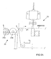
- Figures 5A to 5C shows an example of a continuous production line for producing a four-layer laminate constituted by a bottom spunbonded nonwoven web S made of continuous spun filaments, a first intermediate meltblown web MBW1, a second intermediate fibrous-containing meltblown web MBW2, a third intermediate fibrous-containing meltblown web MBW3, and top fibrous-containing meltblown web MBW4.
- this production line 2 comprises ( figure 5A ) supplying means 20 for continuously providing the bottom spunbonded nonwoven web S onto a conveyor belt 21.
- these supplying means 20 comprise a storage roll 20a around which the spunbonded nonwoven S is being wounded, and a motorized roll 20b associated with the storage roll 20a and adapted to continuously unwind the spunbonded nonwoven web S from the storage roll 20a and to lay down the spunbonded nonwoven web S onto the conveyor belt 21.
- These supplying means 20 can also be replaced by a spunbonded unit adapted to produce in line a spunbonded nonwoven web S made of continuous spun filaments that are laid down randomly directly onto the conveyor belt 21
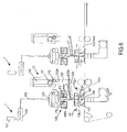
- the production line 2 comprises successively four apparatus 22, 23 ( figure 5B ), 24 and 25 ( Figure 5C ).
- Apparatus 23, 24, 25 are identical to the apparatus 1 previously described in reference to figure 1 .
- the apparatus 22 is similar to the apparatus 1 of figure 1 , but does not comprise fibrous material supplying means.
- the first apparatus 22 is used for continuously spinning the first meltblown web MBW1 directly onto the spunbonded nonwoven web S.
- the second apparatus 23 is used for continuously spinning the second intermediate fibrous-containing meltblown web MBW2 directly onto the first meltblown web MBW1.
- the third apparatus 24 is used for continuously spinning the third fibrous-containing meltblown web MBW3 directly onto the second intermediate fibrous-containing meltblown web MBW2.
- the fourth apparatus 25 is used for continuously spinning the fibrous-containing meltblown web MBW4 directly onto the third intermediate fibrous-containing meltblown web MBW3
- the laminate MBW4/MBW3/MBW2/MBW1/S is then subsequently transported to a standard thermal bonding unit 26, in order to heat bond the different layers of the laminate and obtain a consolidated laminate.
- the consolidated laminate MBW4/MBW3/MBW2/MBW1/S is then knowingly wounded in line around a storage roll 27a.
- meltblown fibres of the first and fourth meltblown nonwoven web MBW1 and MBW4 are bilobal or trilobal and the meltblown fibres of the second and third meltblown nonwoven web MBW2 and MBW3 can have any shape, and in particular can be round.
- the invention is however not limited to such a particular laminate.
- a laminate comprising at least one fibrous-containing meltblown web of the invention, laminated with one or more other layers, including notably spunbonded layer, carded layer, meltblown layer, plastic film, can advantageously be produced.
- the fibrous-containing meltblown web of the invention or a laminate comprising at least one fibrous-containing meltblown web of the invention can be used advantageously for making absorbent products, and more particularly dry wipes, or wet wipes, or diapers, or training pants, or sanitary napkins, or incontinence products, or bed pads.
- Figure 6 shows another variant of a spinning apparatus 1' of the invention that can be used for making a fibrous-containing nonwoven NW.
- the died head 104' of the spinning apparatus 1' is modified in order to extrude several rows (three rows in this particular example) of polymeric filaments f, instead of one row for the apparatus of figure 1 .
- this spinning apparatus 1' there is no generation in the die head 104' of any primary hot air F1, and the polymeric filaments f are only extruded through the spinning orifices of the die head 104'.
- a cooling unit 106 is mounted below the outlet of the die head.
- Said cooling unit 106 comprises two blowing boxes 106a positioned on each side of the filaments f and adapted to blow several transverse forced air flows F6 towards the filaments f, in order to cool down and quench the filaments f, in a way similar to the quenching air used in a standard spunbonding apparatus.
- This quenching air F6 is for example at a temperature between 5 °C and 20°C.
- the same drawing unit 105 as the one previously described is being used at a position below the cooling unit 106 for generating the same air flows F3 oriented downstream as the ones previously described, said air flows F3 drawing and attenuating the filaments f.
- fibrous material supplying means 13' are also provided.
- Said fibrous material supplying means 13' comprise also a vertical chimney 130 which is pneumatically fed in its upper part with the fibrous material FM.
- the supplying means 13' comprises two feeding counter-rotating rolls 131, 132, that longitudinally extend in the cross-machine direction on substantially the whole width of the chimney 130.
- the lower roll 132 is provided with tooth 132a on its whole periphery.
- the supplying means 13' also comprise a feeding channel 133' that is positioned below the feeding roll 132.
- This feeding channel 133' has an outlet 133a for the fibrous material MF.
- Said outlet 133a forms a longitudinal slot and is positioned between the cooling unit 106 and the drawing unit 105, and nearby the curtains of filaments f.
- This longitudinal slot-type outlet 133a extends in the cross-direction direction (direction perpendicular to the figure 6 ) substantially on the whole width of the curtain of filaments f, in order to feed fibrous material MF substantially on the whole width of the curtains of filaments f.
- the supplying means 13' of figure 6 do not comprise blowing means 134, but comprise a conveyor belt 135 forming the lower wall of the feeding channel 133' and adapted to transport the fibrous material FM down to the outlet 133a.
- the fibrous material F is stacked in the chimney 130.
- the conveyor belt 135 is continuously rotated.
- the rolls 131,132 are rotated in order to continuously feed the conveyor belt 135 with fibrous material MF.
- Said fibrous material MF is entrained by the conveyor belt 135 and is continuously delivered nearby to the curtains of filaments f.
- a guiding channel 106 delimited by flaps107 and air ducts 108 is extending between the outlet of the air drawing unit 105 and the conveyor belt 11.
- a guiding channel 106 has been previously disclosed in US patent application US 2008/0317895 which is incorporated therein by reference.
- air is sucked (arrows F7) from the outside of the guiding channel 106 and enters into the guiding channel 106 through air ducts 108, in order to equilibrate the air pressure inside the guiding channel 106.
- the apparatus of figure 1 can also be equipped with such guiding channel 106, flaps 107 and air ducts 108.
- two successive spinning apparatus 1' are provided with the same conveyor belt 11.
- the spinning apparatus 1' can be used alone or in combination with any other type of apparatus adapted to laminate any kind of layer ( textile layer or film) with the fibrous-containing nonwoven NW produced by the spinning apparatus 1'.
Landscapes
- Engineering & Computer Science (AREA)
- Textile Engineering (AREA)
- Mechanical Engineering (AREA)
- Spinning Methods And Devices For Manufacturing Artificial Fibers (AREA)
- Nonwoven Fabrics (AREA)
Priority Applications (5)
| Application Number | Priority Date | Filing Date | Title |
|---|---|---|---|
| PL11743819T PL2603626T3 (pl) | 2010-08-12 | 2011-08-10 | Sposób oraz aparat do przędzenia włókien, a zwłaszcza do wytwarzania zawierającego włókna materiału włókninowego |
| EP11743819.2A EP2603626B9 (en) | 2010-08-12 | 2011-08-10 | Process and apparatus for spinning fibres and in particular for producing a fibrous-containing nonwoven |
| SI201130414T SI2603626T1 (sl) | 2010-08-12 | 2011-08-10 | Postopek in naprava za navijanje vlaken, še posebej za izdelavo netkanega vlaknastega materiala |
| EP14184007.4A EP2845936B1 (en) | 2010-08-12 | 2011-08-10 | Process and apparatus for spinning fibres |
| HRP20150212AT HRP20150212T1 (en) | 2010-08-12 | 2015-02-24 | Process and apparatus for spinning fibres and in particular for producing a fibrous-containing nonwoven |
Applications Claiming Priority (4)
| Application Number | Priority Date | Filing Date | Title |
|---|---|---|---|
| EP10172606 | 2010-08-12 | ||
| US201161468118P | 2011-03-28 | 2011-03-28 | |
| EP11743819.2A EP2603626B9 (en) | 2010-08-12 | 2011-08-10 | Process and apparatus for spinning fibres and in particular for producing a fibrous-containing nonwoven |
| PCT/EP2011/063770 WO2012020053A1 (en) | 2010-08-12 | 2011-08-10 | Process and apparatus for spinning fibres and in particular for producing a fibrous-containing nonwoven |
Related Child Applications (2)
| Application Number | Title | Priority Date | Filing Date |
|---|---|---|---|
| EP14184007.4A Division EP2845936B1 (en) | 2010-08-12 | 2011-08-10 | Process and apparatus for spinning fibres |
| EP14184007.4A Division-Into EP2845936B1 (en) | 2010-08-12 | 2011-08-10 | Process and apparatus for spinning fibres |
Publications (3)
| Publication Number | Publication Date |
|---|---|
| EP2603626A1 EP2603626A1 (en) | 2013-06-19 |
| EP2603626B1 EP2603626B1 (en) | 2014-11-26 |
| EP2603626B9 true EP2603626B9 (en) | 2015-11-04 |
Family
ID=43587315
Family Applications (2)
| Application Number | Title | Priority Date | Filing Date |
|---|---|---|---|
| EP14184007.4A Not-in-force EP2845936B1 (en) | 2010-08-12 | 2011-08-10 | Process and apparatus for spinning fibres |
| EP11743819.2A Active EP2603626B9 (en) | 2010-08-12 | 2011-08-10 | Process and apparatus for spinning fibres and in particular for producing a fibrous-containing nonwoven |
Family Applications Before (1)
| Application Number | Title | Priority Date | Filing Date |
|---|---|---|---|
| EP14184007.4A Not-in-force EP2845936B1 (en) | 2010-08-12 | 2011-08-10 | Process and apparatus for spinning fibres |
Country Status (23)
| Country | Link |
|---|---|
| US (1) | US9617658B2 (es) |
| EP (2) | EP2845936B1 (es) |
| JP (2) | JP5894598B2 (es) |
| KR (1) | KR20130098330A (es) |
| CN (1) | CN103210133B (es) |
| AU (2) | AU2011288452B2 (es) |
| BR (1) | BR112013003040A2 (es) |
| CA (1) | CA2807482C (es) |
| CO (1) | CO6670547A2 (es) |
| DK (1) | DK2603626T3 (es) |
| ES (1) | ES2530952T3 (es) |
| HR (1) | HRP20150212T1 (es) |
| IL (1) | IL224653A (es) |
| MX (1) | MX2013001672A (es) |
| PL (1) | PL2603626T3 (es) |
| PT (1) | PT2603626E (es) |
| RS (1) | RS53822B1 (es) |
| RU (1) | RU2602481C2 (es) |
| SG (1) | SG187822A1 (es) |
| SI (1) | SI2603626T1 (es) |
| UA (1) | UA112528C2 (es) |
| WO (1) | WO2012020053A1 (es) |
| ZA (1) | ZA201301097B (es) |
Families Citing this family (21)
| Publication number | Priority date | Publication date | Assignee | Title |
|---|---|---|---|---|
| DE102012004227A1 (de) * | 2012-03-06 | 2013-09-12 | Carl Freudenberg Kg | Verfahren und Vorrichtung zur Herstellung von superfeinen Polymerfasern durch Melt-blown-Technik |
| TR201808524T4 (tr) | 2014-04-07 | 2018-07-23 | Boma Eng S P A | Lif içeren ve/veya partikül içeren dokunmamış materyeli üretmeye yönelik proses ve aparat. |
| KR102302375B1 (ko) * | 2014-08-27 | 2021-09-15 | 도레이 카부시키가이샤 | 멜트 블로 부직포 및 그 제조 방법 |
| JP6450145B2 (ja) * | 2014-10-30 | 2019-01-09 | 日本製紙クレシア株式会社 | 対人ワイピング用不織布シート |
| TWI621742B (zh) * | 2014-11-26 | 2018-04-21 | 使用熔噴方式製備具有吸濕轉移性不織布的方法 | |
| TWI632259B (zh) * | 2014-11-26 | 2018-08-11 | 聚泰環保材料科技股份有限公司 | Method for preparing moisture-absorbing transfer non-woven fabric by using spunbonding method |
| TWI621743B (zh) * | 2014-11-26 | 2018-04-21 | Method for preparing moisture-absorbing transfer non-woven fabric by using short fiber spinning method | |
| CN104630913B (zh) * | 2015-02-05 | 2017-04-05 | 欣龙控股(集团)股份有限公司 | 用于熔喷法非织造布生产的喷雾冷却方法及其装置 |
| US11313052B2 (en) * | 2015-08-14 | 2022-04-26 | The Board Of Regents Of The University Of Oklahoma | Melt blowing apparatus and method |
| DE102016010163A1 (de) * | 2016-08-25 | 2018-03-01 | Carl Freudenberg Kg | Technisches Verpackungsmaterial |
| GB201619482D0 (en) | 2016-11-17 | 2017-01-04 | Teknoweb Marterials S R L | Triple head draw slot for producing pulp and spunmelt fibers containing web |
| RU2743183C1 (ru) | 2017-03-27 | 2021-02-15 | Селларз Абсорбент Матириалз, Инк. | Впитывающий многослойный материал |
| CN106995983A (zh) * | 2017-04-10 | 2017-08-01 | 河南工程学院 | 一种双组份熔喷超细纤维网的生产方法 |
| US11447893B2 (en) | 2017-11-22 | 2022-09-20 | Extrusion Group, LLC | Meltblown die tip assembly and method |
| CN108866828A (zh) * | 2018-06-26 | 2018-11-23 | 海宁市御纺织造有限责任公司 | 一种含有短纤维的熔喷非织造布加工方法 |
| AU2019457337A1 (en) * | 2019-07-18 | 2021-12-16 | Essity Hygiene And Health Aktiebolag | Composite nonwoven sheet material |
| CN112064202B (zh) * | 2020-09-04 | 2022-12-30 | 平湖爱之馨环保科技有限公司 | 一种纤维制备辅助拉伸设备及方法 |
| CN112411014A (zh) * | 2020-10-12 | 2021-02-26 | 上海科械世贸易有限公司 | 含纳米银线的熔喷布的生产设备及制造方法 |
| DE102021003877A1 (de) | 2021-07-27 | 2023-02-02 | Oerlikon Textile Gmbh & Co. Kg | Vorrichtung zum Ablegen feiner Filamente zu einem Vlies |
| CN113684609A (zh) * | 2021-09-04 | 2021-11-23 | 湖南仁瑞无纺制品有限公司 | 一种熔喷无纺布加工装置 |
| CN115233324B (zh) * | 2022-08-05 | 2023-11-03 | 常州德利斯护理用品有限公司 | 一种制备不同截面异型纤维的纺黏牵伸装置 |
Family Cites Families (36)
| Publication number | Priority date | Publication date | Assignee | Title |
|---|---|---|---|---|
| US3849241A (en) | 1968-12-23 | 1974-11-19 | Exxon Research Engineering Co | Non-woven mats by melt blowing |
| US4048364A (en) | 1974-12-20 | 1977-09-13 | Exxon Research And Engineering Company | Post-drawn, melt-blown webs |
| DE3151294C2 (de) * | 1981-12-24 | 1986-01-23 | Fa. Carl Freudenberg, 6940 Weinheim | Polypropylen-Spinnvliesstoff mit niedrigem Fallkoeffizienten |
| US4604313A (en) * | 1984-04-23 | 1986-08-05 | Kimberly-Clark Corporation | Selective layering of superabsorbents in meltblown substrates |
| US4724114A (en) | 1984-04-23 | 1988-02-09 | Kimberly-Clark Corporation | Selective layering of superabsorbents in meltblown substrates |
| DE3720031A1 (de) * | 1987-06-16 | 1989-01-05 | Freudenberg Carl Fa | Saugkoerper aus vliesstoff und verfahren zu seiner herstellung |
| US4939016A (en) | 1988-03-18 | 1990-07-03 | Kimberly-Clark Corporation | Hydraulically entangled nonwoven elastomeric web and method of forming the same |
| US4931355A (en) | 1988-03-18 | 1990-06-05 | Radwanski Fred R | Nonwoven fibrous hydraulically entangled non-elastic coform material and method of formation thereof |
| DE3810596A1 (de) * | 1988-03-29 | 1989-10-12 | Bayer Ag | Feinstfasern aus polyphenylsulfid |
| AU8275591A (en) | 1990-08-29 | 1992-03-05 | Chicopee | Spacer bar assembly for a melt blown die apparatus |
| US5075068A (en) * | 1990-10-11 | 1991-12-24 | Exxon Chemical Patents Inc. | Method and apparatus for treating meltblown filaments |
| US5350624A (en) * | 1992-10-05 | 1994-09-27 | Kimberly-Clark Corporation | Abrasion resistant fibrous nonwoven composite structure |
| US5503782A (en) * | 1993-01-28 | 1996-04-02 | Minnesota Mining And Manufacturing Company | Method of making sorbent articles |
| JP3418692B2 (ja) * | 1995-03-20 | 2003-06-23 | 株式会社高分子加工研究所 | 超高分子量ポリオレフィンフィラメントの製法 |
| US5648041A (en) * | 1995-05-05 | 1997-07-15 | Conoco Inc. | Process and apparatus for collecting fibers blow spun from solvated mesophase pitch |
| US5672415A (en) * | 1995-11-30 | 1997-09-30 | Kimberly-Clark Worldwide, Inc. | Low density microfiber nonwoven fabric |
| US5863565A (en) * | 1996-05-15 | 1999-01-26 | Conoco Inc. | Apparatus for forming a single layer batt from multiple curtains of fibers |
| US6001303A (en) * | 1997-12-19 | 1999-12-14 | Kimberly-Clark Worldwide, Inc. | Process of making fibers |
| US6368533B1 (en) * | 1997-12-22 | 2002-04-09 | Kimberly-Clark Worldwide, Inc. | Process for forming films, fibers and base webs from thermoset polymers |
| UA30873A (uk) | 1998-06-15 | 2000-12-15 | Криворізький Технічний Університет | Пристрій для автоматичного вимірювання маси вантажу на кар'єрних автосамоскидах |
| US6417120B1 (en) * | 1998-12-31 | 2002-07-09 | Kimberly-Clark Worldwide, Inc. | Particle-containing meltblown webs |
| JP3335949B2 (ja) * | 1999-05-27 | 2002-10-21 | 有限会社末富エンジニアリング | メルトブロー式不織布の紡糸ダイ |
| JP3865534B2 (ja) * | 1999-07-05 | 2007-01-10 | ユニ・チャーム株式会社 | 弾性伸縮性複合シートの製造方法 |
| JP3662455B2 (ja) | 1999-11-22 | 2005-06-22 | ユニ・チャーム株式会社 | ポリプロピレン製不織布およびその製造方法 |
| US20020019614A1 (en) * | 2000-05-17 | 2002-02-14 | Woon Paul S. | Absorbent articles having improved performance |
| US6562282B1 (en) | 2000-07-20 | 2003-05-13 | Rtica, Inc. | Method of melt blowing polymer filaments through alternating slots |
| CN100549265C (zh) * | 2000-08-04 | 2009-10-14 | 纳幕尔杜邦公司 | 熔喷法非织造布 |
| US6692868B2 (en) | 2001-12-19 | 2004-02-17 | Daramic, Inc. | Melt blown battery separator |
| US20030116874A1 (en) * | 2001-12-21 | 2003-06-26 | Haynes Bryan David | Air momentum gage for controlling nonwoven processes |
| JP4339054B2 (ja) * | 2003-09-10 | 2009-10-07 | 株式会社パイオラックス | グロメット |
| US7150616B2 (en) * | 2003-12-22 | 2006-12-19 | Kimberly-Clark Worldwide, Inc | Die for producing meltblown multicomponent fibers and meltblown nonwoven fabrics |
| ES2287619T3 (es) | 2004-09-17 | 2007-12-16 | REIFENHAUSER GMBH & CO. KG MASCHINENFABRIK | Dispositivo para la fabricacion de filamentos de material termoplastico. |
| CN101027442B (zh) | 2004-09-24 | 2010-06-16 | 阿尔比斯有限公司 | 用来将合成纤维铺放成无纺布的装置 |
| CN1920149B (zh) * | 2006-09-18 | 2011-05-04 | 中国纺织科学研究院 | 含有短纤维熔喷无纺布的制备方法 |
| US8246898B2 (en) | 2007-03-19 | 2012-08-21 | Conrad John H | Method and apparatus for enhanced fiber bundle dispersion with a divergent fiber draw unit |
| DE602008004316D1 (de) | 2008-05-14 | 2011-02-17 | Albis Spa | Spinndüse mit zweilappigen Spinnöffnungen |
-
2011
- 2011-08-10 SG SG2013010483A patent/SG187822A1/en unknown
- 2011-08-10 JP JP2013523608A patent/JP5894598B2/ja not_active Expired - Fee Related
- 2011-08-10 EP EP14184007.4A patent/EP2845936B1/en not_active Not-in-force
- 2011-08-10 MX MX2013001672A patent/MX2013001672A/es active IP Right Grant
- 2011-08-10 RS RS20150115A patent/RS53822B1/en unknown
- 2011-08-10 US US13/816,079 patent/US9617658B2/en active Active
- 2011-08-10 SI SI201130414T patent/SI2603626T1/sl unknown
- 2011-08-10 ES ES11743819T patent/ES2530952T3/es active Active
- 2011-08-10 DK DK11743819.2T patent/DK2603626T3/en active
- 2011-08-10 PL PL11743819T patent/PL2603626T3/pl unknown
- 2011-08-10 RU RU2013109811/12A patent/RU2602481C2/ru not_active IP Right Cessation
- 2011-08-10 PT PT11743819T patent/PT2603626E/pt unknown
- 2011-08-10 BR BR112013003040A patent/BR112013003040A2/pt not_active IP Right Cessation
- 2011-08-10 CN CN201180049605.4A patent/CN103210133B/zh not_active Expired - Fee Related
- 2011-08-10 KR KR1020137005896A patent/KR20130098330A/ko not_active Application Discontinuation
- 2011-08-10 WO PCT/EP2011/063770 patent/WO2012020053A1/en active Application Filing
- 2011-08-10 AU AU2011288452A patent/AU2011288452B2/en not_active Ceased
- 2011-08-10 CA CA2807482A patent/CA2807482C/en active Active
- 2011-08-10 EP EP11743819.2A patent/EP2603626B9/en active Active
- 2011-10-08 UA UAA201302830A patent/UA112528C2/uk unknown
-
2013
- 2013-02-10 IL IL224653A patent/IL224653A/en active IP Right Grant
- 2013-02-11 ZA ZA2013/01097A patent/ZA201301097B/en unknown
- 2013-02-12 CO CO13028592A patent/CO6670547A2/es unknown
-
2015
- 2015-02-24 HR HRP20150212AT patent/HRP20150212T1/hr unknown
-
2016
- 2016-02-02 JP JP2016018030A patent/JP2016145442A/ja active Pending
- 2016-05-02 AU AU2016202798A patent/AU2016202798A1/en not_active Abandoned
Also Published As
Similar Documents
| Publication | Publication Date | Title |
|---|---|---|
| EP2603626B1 (en) | Process and apparatus for spinning fibres and in particular for producing a fibrous-containing nonwoven | |
| AU2009329154B2 (en) | A nonwoven composite and method for making the same | |
| US20050227564A1 (en) | Shaped fiber fabrics | |
| US20050227563A1 (en) | Shaped fiber fabrics | |
| US20050176326A1 (en) | Shaped fiber fabrics | |
| US20060012072A1 (en) | Forming shaped fiber fabrics | |
| CN1282782C (zh) | 熔喷纤网 | |
| EP1101854A1 (en) | Nonwoven fabric of polypropylene fiber and process for making the same | |
| KR100713760B1 (ko) | 멜트블로운 웹 | |
| US20100159774A1 (en) | Nonwoven composite and method for making the same | |
| US20190284740A1 (en) | Triple head draw slot for producing pulp and spunmelt fibers containing web | |
| JP4334342B2 (ja) | フィラメント延伸ジェット装置および方法 | |
| CA3088003C (en) | Lofty nonwoven fabrics | |
| CN118207688A (zh) | 形成复合无纺布的方法 |
Legal Events
| Date | Code | Title | Description |
|---|---|---|---|
| PUAI | Public reference made under article 153(3) epc to a published international application that has entered the european phase |
Free format text: ORIGINAL CODE: 0009012 |
|
| 17P | Request for examination filed |
Effective date: 20130221 |
|
| AK | Designated contracting states |
Kind code of ref document: A1 Designated state(s): AL AT BE BG CH CY CZ DE DK EE ES FI FR GB GR HR HU IE IS IT LI LT LU LV MC MK MT NL NO PL PT RO RS SE SI SK SM TR |
|
| AX | Request for extension of the european patent |
Extension state: BA ME |
|
| 17Q | First examination report despatched |
Effective date: 20140214 |
|
| GRAP | Despatch of communication of intention to grant a patent |
Free format text: ORIGINAL CODE: EPIDOSNIGR1 |
|
| GRAC | Information related to communication of intention to grant a patent modified |
Free format text: ORIGINAL CODE: EPIDOSCIGR1 |
|
| INTG | Intention to grant announced |
Effective date: 20140401 |
|
| GRAJ | Information related to disapproval of communication of intention to grant by the applicant or resumption of examination proceedings by the epo deleted |
Free format text: ORIGINAL CODE: EPIDOSDIGR1 |
|
| INTG | Intention to grant announced |
Effective date: 20140415 |
|
| GRAP | Despatch of communication of intention to grant a patent |
Free format text: ORIGINAL CODE: EPIDOSNIGR1 |
|
| INTG | Intention to grant announced |
Effective date: 20140520 |
|
| GRAS | Grant fee paid |
Free format text: ORIGINAL CODE: EPIDOSNIGR3 |
|
| GRAA | (expected) grant |
Free format text: ORIGINAL CODE: 0009210 |
|
| AK | Designated contracting states |
Kind code of ref document: B1 Designated state(s): AL AT BE BG CH CY CZ DE DK EE ES FI FR GB GR HR HU IE IS IT LI LT LU LV MC MK MT NL NO PL PT RO RS SE SI SK SM TR |
|
| AX | Request for extension of the european patent |
Extension state: BA ME |
|
| REG | Reference to a national code |
Ref country code: GB Ref legal event code: FG4D |
|
| REG | Reference to a national code |
Ref country code: CH Ref legal event code: EP |
|
| REG | Reference to a national code |
Ref country code: AT Ref legal event code: REF Ref document number: 698296 Country of ref document: AT Kind code of ref document: T Effective date: 20141215 |
|
| REG | Reference to a national code |
Ref country code: IE Ref legal event code: FG4D |
|
| REG | Reference to a national code |
Ref country code: DE Ref legal event code: R096 Ref document number: 602011011738 Country of ref document: DE Effective date: 20150108 |
|
| REG | Reference to a national code |
Ref country code: RO Ref legal event code: EPE |
|
| REG | Reference to a national code |
Ref country code: HR Ref legal event code: TUEP Ref document number: P20150212 Country of ref document: HR Ref country code: PT Ref legal event code: SC4A Free format text: AVAILABILITY OF NATIONAL TRANSLATION Effective date: 20150216 |
|
| REG | Reference to a national code |
Ref country code: DK Ref legal event code: T3 Effective date: 20150223 |
|
| REG | Reference to a national code |
Ref country code: NL Ref legal event code: T3 |
|
| REG | Reference to a national code |
Ref country code: ES Ref legal event code: FG2A Ref document number: 2530952 Country of ref document: ES Kind code of ref document: T3 Effective date: 20150309 |
|
| REG | Reference to a national code |
Ref country code: SE Ref legal event code: TRGR |
|
| REG | Reference to a national code |
Ref country code: HR Ref legal event code: T1PR Ref document number: P20150212 Country of ref document: HR |
|
| REG | Reference to a national code |
Ref country code: GR Ref legal event code: EP Ref document number: 20150400435 Country of ref document: GR Effective date: 20150318 |
|
| REG | Reference to a national code |
Ref country code: LT Ref legal event code: MG4D |
|
| PG25 | Lapsed in a contracting state [announced via postgrant information from national office to epo] |
Ref country code: IS Free format text: LAPSE BECAUSE OF FAILURE TO SUBMIT A TRANSLATION OF THE DESCRIPTION OR TO PAY THE FEE WITHIN THE PRESCRIBED TIME-LIMIT Effective date: 20150326 Ref country code: LT Free format text: LAPSE BECAUSE OF FAILURE TO SUBMIT A TRANSLATION OF THE DESCRIPTION OR TO PAY THE FEE WITHIN THE PRESCRIBED TIME-LIMIT Effective date: 20141126 |
|
| REG | Reference to a national code |
Ref country code: NO Ref legal event code: T2 Effective date: 20141126 |
|
| REG | Reference to a national code |
Ref country code: SK Ref legal event code: T3 Ref document number: E 18118 Country of ref document: SK |
|
| PG25 | Lapsed in a contracting state [announced via postgrant information from national office to epo] |
Ref country code: CY Free format text: LAPSE BECAUSE OF FAILURE TO SUBMIT A TRANSLATION OF THE DESCRIPTION OR TO PAY THE FEE WITHIN THE PRESCRIBED TIME-LIMIT Effective date: 20141126 Ref country code: LV Free format text: LAPSE BECAUSE OF FAILURE TO SUBMIT A TRANSLATION OF THE DESCRIPTION OR TO PAY THE FEE WITHIN THE PRESCRIBED TIME-LIMIT Effective date: 20141126 |
|
| REG | Reference to a national code |
Ref country code: PL Ref legal event code: T3 |
|
| PG25 | Lapsed in a contracting state [announced via postgrant information from national office to epo] |
Ref country code: EE Free format text: LAPSE BECAUSE OF FAILURE TO SUBMIT A TRANSLATION OF THE DESCRIPTION OR TO PAY THE FEE WITHIN THE PRESCRIBED TIME-LIMIT Effective date: 20141126 |
|
| REG | Reference to a national code |
Ref country code: DE Ref legal event code: R097 Ref document number: 602011011738 Country of ref document: DE |
|
| REG | Reference to a national code |
Ref country code: HU Ref legal event code: AG4A Ref document number: E023839 Country of ref document: HU |
|
| PLBE | No opposition filed within time limit |
Free format text: ORIGINAL CODE: 0009261 |
|
| STAA | Information on the status of an ep patent application or granted ep patent |
Free format text: STATUS: NO OPPOSITION FILED WITHIN TIME LIMIT |
|
| 26N | No opposition filed |
Effective date: 20150827 |
|
| PG25 | Lapsed in a contracting state [announced via postgrant information from national office to epo] |
Ref country code: MC Free format text: LAPSE BECAUSE OF FAILURE TO SUBMIT A TRANSLATION OF THE DESCRIPTION OR TO PAY THE FEE WITHIN THE PRESCRIBED TIME-LIMIT Effective date: 20141126 |
|
| REG | Reference to a national code |
Ref country code: DE Ref legal event code: R082 Ref document number: 602011011738 Country of ref document: DE Representative=s name: LEONHARD & PARTNER PATENTANWAELTE, DE Ref country code: DE Ref legal event code: R081 Ref document number: 602011011738 Country of ref document: DE Owner name: BOMA ENGINEERING S.P.A., IT Free format text: FORMER OWNER: BOMA ENGINEERING SRL, MILANO, IT |
|
| REG | Reference to a national code |
Ref country code: AT Ref legal event code: UEP Ref document number: 698296 Country of ref document: AT Kind code of ref document: T Effective date: 20141126 |
|
| REG | Reference to a national code |
Ref country code: FR Ref legal event code: PLFP Year of fee payment: 6 |
|
| PG25 | Lapsed in a contracting state [announced via postgrant information from national office to epo] |
Ref country code: MT Free format text: LAPSE BECAUSE OF FAILURE TO SUBMIT A TRANSLATION OF THE DESCRIPTION OR TO PAY THE FEE WITHIN THE PRESCRIBED TIME-LIMIT Effective date: 20141126 |
|
| PG25 | Lapsed in a contracting state [announced via postgrant information from national office to epo] |
Ref country code: SM Free format text: LAPSE BECAUSE OF FAILURE TO SUBMIT A TRANSLATION OF THE DESCRIPTION OR TO PAY THE FEE WITHIN THE PRESCRIBED TIME-LIMIT Effective date: 20141126 |
|
| REG | Reference to a national code |
Ref country code: FR Ref legal event code: PLFP Year of fee payment: 7 |
|
| REG | Reference to a national code |
Ref country code: HR Ref legal event code: ODRP Ref document number: P20150212 Country of ref document: HR Payment date: 20170803 Year of fee payment: 7 |
|
| PGFP | Annual fee paid to national office [announced via postgrant information from national office to epo] |
Ref country code: NL Payment date: 20170821 Year of fee payment: 7 Ref country code: LU Payment date: 20170821 Year of fee payment: 7 |
|
| PGFP | Annual fee paid to national office [announced via postgrant information from national office to epo] |
Ref country code: HR Payment date: 20170803 Year of fee payment: 7 Ref country code: NO Payment date: 20170824 Year of fee payment: 7 Ref country code: ES Payment date: 20170911 Year of fee payment: 7 Ref country code: FR Payment date: 20170728 Year of fee payment: 7 Ref country code: FI Payment date: 20170822 Year of fee payment: 7 Ref country code: CH Payment date: 20170825 Year of fee payment: 7 Ref country code: GR Payment date: 20170823 Year of fee payment: 7 Ref country code: SK Payment date: 20170803 Year of fee payment: 7 Ref country code: RO Payment date: 20170804 Year of fee payment: 7 Ref country code: GB Payment date: 20170728 Year of fee payment: 7 |
|
| PGFP | Annual fee paid to national office [announced via postgrant information from national office to epo] |
Ref country code: HU Payment date: 20170922 Year of fee payment: 7 Ref country code: SE Payment date: 20170731 Year of fee payment: 7 Ref country code: IE Payment date: 20170822 Year of fee payment: 7 Ref country code: BE Payment date: 20170728 Year of fee payment: 7 Ref country code: SI Payment date: 20170801 Year of fee payment: 7 Ref country code: RS Payment date: 20170802 Year of fee payment: 7 Ref country code: AT Payment date: 20170822 Year of fee payment: 7 Ref country code: BG Payment date: 20170801 Year of fee payment: 7 Ref country code: PT Payment date: 20170724 Year of fee payment: 7 |
|
| PGFP | Annual fee paid to national office [announced via postgrant information from national office to epo] |
Ref country code: MK Payment date: 20170731 Year of fee payment: 7 |
|
| PG25 | Lapsed in a contracting state [announced via postgrant information from national office to epo] |
Ref country code: AL Free format text: LAPSE BECAUSE OF FAILURE TO SUBMIT A TRANSLATION OF THE DESCRIPTION OR TO PAY THE FEE WITHIN THE PRESCRIBED TIME-LIMIT Effective date: 20141126 |
|
| REG | Reference to a national code |
Ref country code: HR Ref legal event code: PBON Ref document number: P20150212 Country of ref document: HR Effective date: 20180810 |
|
| REG | Reference to a national code |
Ref country code: NO Ref legal event code: MMEP |
|
| REG | Reference to a national code |
Ref country code: CH Ref legal event code: PL |
|
| REG | Reference to a national code |
Ref country code: SE Ref legal event code: EUG |
|
| REG | Reference to a national code |
Ref country code: NL Ref legal event code: MM Effective date: 20180901 |
|
| REG | Reference to a national code |
Ref country code: AT Ref legal event code: MM01 Ref document number: 698296 Country of ref document: AT Kind code of ref document: T Effective date: 20180810 |
|
| GBPC | Gb: european patent ceased through non-payment of renewal fee |
Effective date: 20180810 |
|
| PG25 | Lapsed in a contracting state [announced via postgrant information from national office to epo] |
Ref country code: FI Free format text: LAPSE BECAUSE OF NON-PAYMENT OF DUE FEES Effective date: 20180810 Ref country code: RO Free format text: LAPSE BECAUSE OF NON-PAYMENT OF DUE FEES Effective date: 20180810 Ref country code: NO Free format text: LAPSE BECAUSE OF NON-PAYMENT OF DUE FEES Effective date: 20180831 Ref country code: LU Free format text: LAPSE BECAUSE OF NON-PAYMENT OF DUE FEES Effective date: 20180810 Ref country code: HR Free format text: LAPSE BECAUSE OF NON-PAYMENT OF DUE FEES Effective date: 20180810 Ref country code: AT Free format text: LAPSE BECAUSE OF NON-PAYMENT OF DUE FEES Effective date: 20180810 Ref country code: LI Free format text: LAPSE BECAUSE OF NON-PAYMENT OF DUE FEES Effective date: 20180831 Ref country code: CH Free format text: LAPSE BECAUSE OF NON-PAYMENT OF DUE FEES Effective date: 20180831 Ref country code: HU Free format text: LAPSE BECAUSE OF NON-PAYMENT OF DUE FEES Effective date: 20180811 |
|
| REG | Reference to a national code |
Ref country code: SK Ref legal event code: MM4A Ref document number: E 18118 Country of ref document: SK Effective date: 20180810 |
|
| REG | Reference to a national code |
Ref country code: BE Ref legal event code: FP Effective date: 20150224 Ref country code: BE Ref legal event code: MM Effective date: 20180831 |
|
| REG | Reference to a national code |
Ref country code: IE Ref legal event code: MM4A |
|
| PG25 | Lapsed in a contracting state [announced via postgrant information from national office to epo] |
Ref country code: SK Free format text: LAPSE BECAUSE OF NON-PAYMENT OF DUE FEES Effective date: 20180810 Ref country code: SI Free format text: LAPSE BECAUSE OF NON-PAYMENT OF DUE FEES Effective date: 20180811 Ref country code: RS Free format text: LAPSE BECAUSE OF NON-PAYMENT OF DUE FEES Effective date: 20190214 Ref country code: PT Free format text: LAPSE BECAUSE OF NON-PAYMENT OF DUE FEES Effective date: 20190211 Ref country code: SE Free format text: LAPSE BECAUSE OF NON-PAYMENT OF DUE FEES Effective date: 20180811 Ref country code: GR Free format text: LAPSE BECAUSE OF NON-PAYMENT OF DUE FEES Effective date: 20190307 |
|
| REG | Reference to a national code |
Ref country code: SI Ref legal event code: KO00 Effective date: 20190410 |
|
| PG25 | Lapsed in a contracting state [announced via postgrant information from national office to epo] |
Ref country code: NL Free format text: LAPSE BECAUSE OF NON-PAYMENT OF DUE FEES Effective date: 20180901 |
|
| PG25 | Lapsed in a contracting state [announced via postgrant information from national office to epo] |
Ref country code: IE Free format text: LAPSE BECAUSE OF NON-PAYMENT OF DUE FEES Effective date: 20180810 |
|
| PG25 | Lapsed in a contracting state [announced via postgrant information from national office to epo] |
Ref country code: BG Free format text: LAPSE BECAUSE OF NON-PAYMENT OF DUE FEES Effective date: 20190430 Ref country code: BE Free format text: LAPSE BECAUSE OF NON-PAYMENT OF DUE FEES Effective date: 20180831 Ref country code: FR Free format text: LAPSE BECAUSE OF NON-PAYMENT OF DUE FEES Effective date: 20180831 |
|
| REG | Reference to a national code |
Ref country code: ES Ref legal event code: FD2A Effective date: 20190918 |
|
| PG25 | Lapsed in a contracting state [announced via postgrant information from national office to epo] |
Ref country code: ES Free format text: LAPSE BECAUSE OF NON-PAYMENT OF DUE FEES Effective date: 20180811 Ref country code: GB Free format text: LAPSE BECAUSE OF NON-PAYMENT OF DUE FEES Effective date: 20180810 |
|
| REG | Reference to a national code |
Ref country code: DE Ref legal event code: R082 Ref document number: 602011011738 Country of ref document: DE Representative=s name: LEONHARD, REIMUND, DIPL.-ING., DE |
|
| P01 | Opt-out of the competence of the unified patent court (upc) registered |
Effective date: 20230508 |
|
| PGFP | Annual fee paid to national office [announced via postgrant information from national office to epo] |
Ref country code: TR Payment date: 20230731 Year of fee payment: 13 Ref country code: IT Payment date: 20230720 Year of fee payment: 13 Ref country code: CZ Payment date: 20230725 Year of fee payment: 13 |
|
| PGFP | Annual fee paid to national office [announced via postgrant information from national office to epo] |
Ref country code: PL Payment date: 20230724 Year of fee payment: 13 Ref country code: DK Payment date: 20230721 Year of fee payment: 13 Ref country code: DE Payment date: 20230720 Year of fee payment: 13 |