EP2602344A1 - Orientierte elektromagnetische stahlplatte - Google Patents
Orientierte elektromagnetische stahlplatte Download PDFInfo
- Publication number
- EP2602344A1 EP2602344A1 EP11814310.6A EP11814310A EP2602344A1 EP 2602344 A1 EP2602344 A1 EP 2602344A1 EP 11814310 A EP11814310 A EP 11814310A EP 2602344 A1 EP2602344 A1 EP 2602344A1
- Authority
- EP
- European Patent Office
- Prior art keywords
- magnetic domain
- steel sheet
- width
- treatment
- strain
- Prior art date
- Legal status (The legal status is an assumption and is not a legal conclusion. Google has not performed a legal analysis and makes no representation as to the accuracy of the status listed.)
- Granted
Links
- 229910000831 Steel Inorganic materials 0.000 title description 38
- 239000010959 steel Substances 0.000 title description 38
- 230000005381 magnetic domain Effects 0.000 claims abstract description 94
- 229910001224 Grain-oriented electrical steel Inorganic materials 0.000 claims abstract description 24
- 230000004907 flux Effects 0.000 claims abstract description 13
- 238000010894 electron beam technology Methods 0.000 claims description 15
- XEEYBQQBJWHFJM-UHFFFAOYSA-N Iron Chemical group [Fe] XEEYBQQBJWHFJM-UHFFFAOYSA-N 0.000 abstract description 35
- 238000000137 annealing Methods 0.000 description 27
- 239000011248 coating agent Substances 0.000 description 18
- 238000000576 coating method Methods 0.000 description 18
- 230000000052 comparative effect Effects 0.000 description 16
- 238000001953 recrystallisation Methods 0.000 description 16
- 238000000034 method Methods 0.000 description 15
- 229910052742 iron Inorganic materials 0.000 description 12
- 230000005415 magnetization Effects 0.000 description 12
- 230000000694 effects Effects 0.000 description 9
- 238000005096 rolling process Methods 0.000 description 7
- 229910052839 forsterite Inorganic materials 0.000 description 6
- 238000005098 hot rolling Methods 0.000 description 6
- 230000009467 reduction Effects 0.000 description 6
- 239000003112 inhibitor Substances 0.000 description 5
- 238000009413 insulation Methods 0.000 description 5
- HCWCAKKEBCNQJP-UHFFFAOYSA-N magnesium orthosilicate Chemical compound [Mg+2].[Mg+2].[O-][Si]([O-])([O-])[O-] HCWCAKKEBCNQJP-UHFFFAOYSA-N 0.000 description 5
- 239000000463 material Substances 0.000 description 5
- VYPSYNLAJGMNEJ-UHFFFAOYSA-N Silicium dioxide Chemical compound O=[Si]=O VYPSYNLAJGMNEJ-UHFFFAOYSA-N 0.000 description 4
- 229910052782 aluminium Inorganic materials 0.000 description 4
- 230000005284 excitation Effects 0.000 description 4
- 230000033001 locomotion Effects 0.000 description 4
- 238000004519 manufacturing process Methods 0.000 description 4
- 229910052757 nitrogen Inorganic materials 0.000 description 4
- 230000008569 process Effects 0.000 description 4
- 229910052711 selenium Inorganic materials 0.000 description 4
- 229910000976 Electrical steel Inorganic materials 0.000 description 3
- 230000001133 acceleration Effects 0.000 description 3
- 239000013078 crystal Substances 0.000 description 3
- 238000005261 decarburization Methods 0.000 description 3
- 230000006735 deficit Effects 0.000 description 3
- 238000009826 distribution Methods 0.000 description 3
- 230000006872 improvement Effects 0.000 description 3
- 239000012535 impurity Substances 0.000 description 3
- 230000001678 irradiating effect Effects 0.000 description 3
- 230000003287 optical effect Effects 0.000 description 3
- 239000000047 product Substances 0.000 description 3
- 229910052717 sulfur Inorganic materials 0.000 description 3
- 230000015572 biosynthetic process Effects 0.000 description 2
- 239000003990 capacitor Substances 0.000 description 2
- 239000008119 colloidal silica Substances 0.000 description 2
- 150000001875 compounds Chemical class 0.000 description 2
- 239000000835 fiber Substances 0.000 description 2
- 238000010438 heat treatment Methods 0.000 description 2
- 230000001771 impaired effect Effects 0.000 description 2
- 238000003475 lamination Methods 0.000 description 2
- 239000000203 mixture Substances 0.000 description 2
- 238000000746 purification Methods 0.000 description 2
- 238000007670 refining Methods 0.000 description 2
- 230000035882 stress Effects 0.000 description 2
- 239000000126 substance Substances 0.000 description 2
- 238000005303 weighing Methods 0.000 description 2
- 239000000654 additive Substances 0.000 description 1
- 230000032683 aging Effects 0.000 description 1
- ILRRQNADMUWWFW-UHFFFAOYSA-K aluminium phosphate Chemical compound O1[Al]2OP1(=O)O2 ILRRQNADMUWWFW-UHFFFAOYSA-K 0.000 description 1
- 229910052787 antimony Inorganic materials 0.000 description 1
- 238000005266 casting Methods 0.000 description 1
- 238000005524 ceramic coating Methods 0.000 description 1
- 230000008859 change Effects 0.000 description 1
- 238000005229 chemical vapour deposition Methods 0.000 description 1
- 229910052804 chromium Inorganic materials 0.000 description 1
- 238000005097 cold rolling Methods 0.000 description 1
- 238000007796 conventional method Methods 0.000 description 1
- 229910052802 copper Inorganic materials 0.000 description 1
- 230000003247 decreasing effect Effects 0.000 description 1
- 239000012467 final product Substances 0.000 description 1
- 238000010304 firing Methods 0.000 description 1
- 230000002452 interceptive effect Effects 0.000 description 1
- GVALZJMUIHGIMD-UHFFFAOYSA-H magnesium phosphate Chemical compound [Mg+2].[Mg+2].[Mg+2].[O-]P([O-])([O-])=O.[O-]P([O-])([O-])=O GVALZJMUIHGIMD-UHFFFAOYSA-H 0.000 description 1
- 239000004137 magnesium phosphate Substances 0.000 description 1
- 229960002261 magnesium phosphate Drugs 0.000 description 1
- 229910000157 magnesium phosphate Inorganic materials 0.000 description 1
- 235000010994 magnesium phosphates Nutrition 0.000 description 1
- 239000000696 magnetic material Substances 0.000 description 1
- 229910052748 manganese Inorganic materials 0.000 description 1
- 238000005259 measurement Methods 0.000 description 1
- 230000007246 mechanism Effects 0.000 description 1
- 229910052750 molybdenum Inorganic materials 0.000 description 1
- 230000010355 oscillation Effects 0.000 description 1
- 229910052698 phosphorus Inorganic materials 0.000 description 1
- 238000005240 physical vapour deposition Methods 0.000 description 1
- 239000004065 semiconductor Substances 0.000 description 1
- 230000035807 sensation Effects 0.000 description 1
- 239000000377 silicon dioxide Substances 0.000 description 1
- 238000001228 spectrum Methods 0.000 description 1
- 239000002344 surface layer Substances 0.000 description 1
- 229910052718 tin Inorganic materials 0.000 description 1
Images
Classifications
-
- H—ELECTRICITY
- H01—ELECTRIC ELEMENTS
- H01F—MAGNETS; INDUCTANCES; TRANSFORMERS; SELECTION OF MATERIALS FOR THEIR MAGNETIC PROPERTIES
- H01F1/00—Magnets or magnetic bodies characterised by the magnetic materials therefor; Selection of materials for their magnetic properties
- H01F1/01—Magnets or magnetic bodies characterised by the magnetic materials therefor; Selection of materials for their magnetic properties of inorganic materials
-
- C—CHEMISTRY; METALLURGY
- C21—METALLURGY OF IRON
- C21D—MODIFYING THE PHYSICAL STRUCTURE OF FERROUS METALS; GENERAL DEVICES FOR HEAT TREATMENT OF FERROUS OR NON-FERROUS METALS OR ALLOYS; MAKING METAL MALLEABLE, e.g. BY DECARBURISATION OR TEMPERING
- C21D8/00—Modifying the physical properties by deformation combined with, or followed by, heat treatment
- C21D8/12—Modifying the physical properties by deformation combined with, or followed by, heat treatment during manufacturing of articles with special electromagnetic properties
- C21D8/1244—Modifying the physical properties by deformation combined with, or followed by, heat treatment during manufacturing of articles with special electromagnetic properties the heat treatment(s) being of interest
- C21D8/1261—Modifying the physical properties by deformation combined with, or followed by, heat treatment during manufacturing of articles with special electromagnetic properties the heat treatment(s) being of interest following hot rolling
-
- C—CHEMISTRY; METALLURGY
- C21—METALLURGY OF IRON
- C21D—MODIFYING THE PHYSICAL STRUCTURE OF FERROUS METALS; GENERAL DEVICES FOR HEAT TREATMENT OF FERROUS OR NON-FERROUS METALS OR ALLOYS; MAKING METAL MALLEABLE, e.g. BY DECARBURISATION OR TEMPERING
- C21D8/00—Modifying the physical properties by deformation combined with, or followed by, heat treatment
- C21D8/12—Modifying the physical properties by deformation combined with, or followed by, heat treatment during manufacturing of articles with special electromagnetic properties
- C21D8/1277—Modifying the physical properties by deformation combined with, or followed by, heat treatment during manufacturing of articles with special electromagnetic properties involving a particular surface treatment
- C21D8/1283—Application of a separating or insulating coating
-
- C—CHEMISTRY; METALLURGY
- C21—METALLURGY OF IRON
- C21D—MODIFYING THE PHYSICAL STRUCTURE OF FERROUS METALS; GENERAL DEVICES FOR HEAT TREATMENT OF FERROUS OR NON-FERROUS METALS OR ALLOYS; MAKING METAL MALLEABLE, e.g. BY DECARBURISATION OR TEMPERING
- C21D8/00—Modifying the physical properties by deformation combined with, or followed by, heat treatment
- C21D8/12—Modifying the physical properties by deformation combined with, or followed by, heat treatment during manufacturing of articles with special electromagnetic properties
- C21D8/1277—Modifying the physical properties by deformation combined with, or followed by, heat treatment during manufacturing of articles with special electromagnetic properties involving a particular surface treatment
- C21D8/1288—Application of a tension-inducing coating
-
- C—CHEMISTRY; METALLURGY
- C21—METALLURGY OF IRON
- C21D—MODIFYING THE PHYSICAL STRUCTURE OF FERROUS METALS; GENERAL DEVICES FOR HEAT TREATMENT OF FERROUS OR NON-FERROUS METALS OR ALLOYS; MAKING METAL MALLEABLE, e.g. BY DECARBURISATION OR TEMPERING
- C21D8/00—Modifying the physical properties by deformation combined with, or followed by, heat treatment
- C21D8/12—Modifying the physical properties by deformation combined with, or followed by, heat treatment during manufacturing of articles with special electromagnetic properties
- C21D8/1294—Modifying the physical properties by deformation combined with, or followed by, heat treatment during manufacturing of articles with special electromagnetic properties involving a localized treatment
-
- C—CHEMISTRY; METALLURGY
- C22—METALLURGY; FERROUS OR NON-FERROUS ALLOYS; TREATMENT OF ALLOYS OR NON-FERROUS METALS
- C22C—ALLOYS
- C22C38/00—Ferrous alloys, e.g. steel alloys
-
- C—CHEMISTRY; METALLURGY
- C22—METALLURGY; FERROUS OR NON-FERROUS ALLOYS; TREATMENT OF ALLOYS OR NON-FERROUS METALS
- C22C—ALLOYS
- C22C38/00—Ferrous alloys, e.g. steel alloys
- C22C38/04—Ferrous alloys, e.g. steel alloys containing manganese
-
- C—CHEMISTRY; METALLURGY
- C22—METALLURGY; FERROUS OR NON-FERROUS ALLOYS; TREATMENT OF ALLOYS OR NON-FERROUS METALS
- C22C—ALLOYS
- C22C38/00—Ferrous alloys, e.g. steel alloys
- C22C38/18—Ferrous alloys, e.g. steel alloys containing chromium
- C22C38/34—Ferrous alloys, e.g. steel alloys containing chromium with more than 1.5% by weight of silicon
-
- H—ELECTRICITY
- H01—ELECTRIC ELEMENTS
- H01F—MAGNETS; INDUCTANCES; TRANSFORMERS; SELECTION OF MATERIALS FOR THEIR MAGNETIC PROPERTIES
- H01F1/00—Magnets or magnetic bodies characterised by the magnetic materials therefor; Selection of materials for their magnetic properties
- H01F1/01—Magnets or magnetic bodies characterised by the magnetic materials therefor; Selection of materials for their magnetic properties of inorganic materials
- H01F1/03—Magnets or magnetic bodies characterised by the magnetic materials therefor; Selection of materials for their magnetic properties of inorganic materials characterised by their coercivity
- H01F1/12—Magnets or magnetic bodies characterised by the magnetic materials therefor; Selection of materials for their magnetic properties of inorganic materials characterised by their coercivity of soft-magnetic materials
- H01F1/14—Magnets or magnetic bodies characterised by the magnetic materials therefor; Selection of materials for their magnetic properties of inorganic materials characterised by their coercivity of soft-magnetic materials metals or alloys
- H01F1/16—Magnets or magnetic bodies characterised by the magnetic materials therefor; Selection of materials for their magnetic properties of inorganic materials characterised by their coercivity of soft-magnetic materials metals or alloys in the form of sheets
-
- C—CHEMISTRY; METALLURGY
- C21—METALLURGY OF IRON
- C21D—MODIFYING THE PHYSICAL STRUCTURE OF FERROUS METALS; GENERAL DEVICES FOR HEAT TREATMENT OF FERROUS OR NON-FERROUS METALS OR ALLOYS; MAKING METAL MALLEABLE, e.g. BY DECARBURISATION OR TEMPERING
- C21D2201/00—Treatment for obtaining particular effects
- C21D2201/05—Grain orientation
-
- C—CHEMISTRY; METALLURGY
- C22—METALLURGY; FERROUS OR NON-FERROUS ALLOYS; TREATMENT OF ALLOYS OR NON-FERROUS METALS
- C22C—ALLOYS
- C22C38/00—Ferrous alloys, e.g. steel alloys
- C22C38/02—Ferrous alloys, e.g. steel alloys containing silicon
Definitions
- the present invention relates to a grain oriented electrical steel sheet that exhibits excellent noise properties and preferably used for the material of iron cores of transformers.
- Grain oriented electrical steel sheets which are mainly used as iron cores of transformers, are required to have excellent magnetic properties, in particular, less iron loss. To meet this requirement, it is important that secondary recrystallized grains are highly aligned in the steel sheet in the (110)[001] orientation (or the Goss orientation) and impurities in the product are reduced.
- JP 57-002252 B proposes a technique for reducing iron loss by irradiating a final product steel sheet with laser, introducing a linear, high dislocation density region to the surface layer of the steel sheet and thereby reducing the magnetic domain width.
- JP 06-072266 B proposes a technique for controlling the magnetic domain width by means of electron beam irradiation.
- electron beam scanning can be performed at high rate by controlling magnetic fields.
- An object of the present invention is to propose a grain oriented electrical steel sheet with reduced iron loss by magnetic domain refinement treatment that exhibits excellent noise properties and may effectively reduce noise generated when used laminated on an iron core of a transformer.
- the noise of a transformer is caused by the magnetostrictive behavior occurring when an electrical steel sheet is magnetized.
- an electrical steel sheet containing about 3 mass % of Si is generally elongated along its magnetization direction.
- the steel sheet undergoes alternating magnetization varying the sign of magnetization between positive and negative around zero, and as a result, the iron core repeatedly expands and contracts, which causes noise.
- magnetostrictive vibration corresponds to the positive and negative signs of magnetization
- the steel sheet will oscillate at a period twice the frequency of the alternating current excitation.
- the fundamental vibration frequency of the magnetostrictive vibration will be 100 Hz.
- the analysis of the frequency of transformer noise shows that the transformer noise contains many high-harmonic components. In many cases, the frequency components of around 200 Hz to 700 Hz are stronger than the frequency component of 100 Hz of the fundamental frequency and thus determine the absolute value of noise.
- Such high-harmonic components are caused by various, extremely complicated factors, including mechanical vibration depending on the shape of the iron core, vibration of a jig for holding the laminated iron core, and so on.
- the observed magnetostrictive vibration contains high-harmonic components at other than 100 Hz of the fundamental frequency even if the steel sheet is excited with a sinusoidal wave at 50 Hz, for example. It is believed that this is ascribed to a change in the magnetic domain structure responsible for the magnetization process of a soft magnetic material.
- the inventors of the present invention have analyzed the behavior of magnetostrictive vibration, focusing on the magnetic domain structure of the grain oriented electrical steel sheet, one side of which had been subjected to magnetic domain control treatment using an electron beam irradiation scheme. As a result, it was revealed that from the viewpoint of reducing iron loss, sufficient effects are obtained by applying linear distortion on only one side of the steel sheet, however, with respect to transformer noise, namely, magnetostrictive vibration, it is extremely important that identical magnetic domain refinement effects are obtained on both sides of the steel sheet.
- the inventors of the present invention have made intensive studies on the relationship between the ratio of the magnetic domain widths observed on both sides of the steel sheet and the frequency component of noise of a model transformer due to the laminated iron core at the time of alternating magnetization of the transformer. As a result, it was found that if there is a difference in magnetic domain width between the both sides, there are different magnetization conditions in the sheet thickness direction.
- a grain oriented electrical steel sheet with reduced iron loss by strain introduction may produce less noise when laminated into a transformer as compared with the conventional techniques.
- transformer noise namely, magnetostrictive vibration
- the higher the degree of alignment of crystal grains of the material with the easy axis of magnetization the smaller the amplitude of oscillation.
- the magnetic flux density B 8 is less than 1.92 T, magnetic domains must perform rotational motion to align parallel to the excitation magnetic field during the magnetization process.
- this magnetization rotation causes a large magnetostriction, which increases the noise of a transformer. Therefore, in the present invention, a grain oriented electrical steel sheet having a magnetic flux density B 8 of 1.92 T or higher is used.
- the magnetic domain structure is modified by strain introduction.
- strain introduction it is important to leave no traces indicative of the strain being introduced to the treated surface.
- the term "grain oriented electrical steel sheet without a trace of treatment” means such an electrical steel sheet whose surface condition is such that the originally-provided tension coating will not be impaired by strain-introducing treatment, i.e., any post-treatment such as recoating will not be required. If the tension coating is locally impaired by strain introduction, the stress distribution originally provided by coating becomes non-uniform and thus the magnetostrictive vibration waveform of the steel sheet is distorted, which induces superimposition of high-harmonic components. Therefore, this is not preferable for noise reduction.
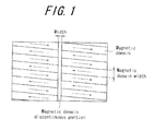
- an average magnetic domain width before the treatment (W 0 ), an average magnetic domain width in a treated surface after the treatment (W a ), and an average magnetic domain width in an untreated surface after the treatment (W b ) are calculated by performing a weighted average of the magnetic domain widths of individual crystal grains depending upon the area ratio.
- the term "magnetic domain width” means the width of main magnetic domains parallel to the rolling direction. Accordingly, the measurement of magnetic domain width is performed in a transverse direction (a direction perpendicular to the rolling direction).
- a ratio of the average magnetic domain width after the treatment to the average magnetic domain width before the treatment (W a /W 0 ) needs to be less than 0.4. If a ratio of the average magnetic domain width after the treatment to the average magnetic domain width before the treatment W a /W 0 is 0.4 or more, the effect of magnetic domain control treatment itself is not enough and iron loss of the steel sheet is not reduced sufficiently.
- a ratio between the average magnetic domain widths on the both sides of the steel sheet (W a /W b ) needs to be more than 0.7.
- the maximum value of W a /W b is about 1.0.
- average width of a magnetic domain discontinuous portion resulting from the strain-introducing treatment means the width of a portion where the magnetic domain structure is locally disrupted by strain, typically indicating a portion at which the magnetic domain structure parallel to the rolling direction is disconnected or discontinued. If the ratio of the average width of the magnetic domain discontinuous portion in the untreated surface W d to the average width of the magnetic domain discontinuous portion in the treated surface W c does not satisfy a relation of W d /W c > 0.8, i.e., if there is a significant difference between the widths of the discontinuous portions on the both sides, there will be a difference in magnetization conditions in the sheet thickness direction of the steel sheet.
- Suitable strain-introducing treatment without a trace of treatment includes, for example, electron beam irradiation, continuous laser irradiation, and so on. Irradiation is preferably performed in a direction transverse to the rolling direction, preferably at 60° to 90° to the rolling direction, and the irradiation interval of the electron beam is preferably about 3 to 15 mm.
- the irradiation interval of the electron beam is preferably about 3 to 15 mm.
- it is preferable to use a large current at a low acceleration voltage it is preferable to use a large current at a low acceleration voltage, and it is effective to apply electron beam in a spot-like or linear fashion with an acceleration voltage of 5 to 50 kV, current of 0.5 to 100 mA and beam diameter of 0.01 to 0.5 mm.
- the power density is preferably in the range of 100 to 5000 W/mm 2 depending on the scanning rate of laser beam.
- Effective excitation sources include fiber laser excited by semiconductor laser, and so on.
- the beam diameter of laser is reduced to about 0.02 mm, and when irradiation is performed in dashed-line form, i.e., in the form of a continuous line interrupted at a constant interval, a reduction in the area of the strain-introduced portion due to the reduced diameter can be compensated for in the form of lines rather than points.
- This small beam diameter allows for reduction in the widths W c and W d of the magnetic domain discontinuous portions as well as the difference therebetween, and furthermore, reduction in the magnetic domain widths W a and W b as well as the difference therebetween.
- the magnetic domain width of the treated surface may be primarily adjusted by controlling the intensity of irradiation energy.
- the difference in magnetic domain width between the treated surface and the untreated surface may be adjusted by controlling the distribution of irradiation energy density. That is, this difference may be adjusted by controlling the depth and range of incidental energy, while switching between in- and out-of focus through beam focus adjustment.
- the magnetic domain discontinuous portion width of the treated surface and the magnetic domain discontinuous portion width of the untreated surface may also be adjusted by controlling the depth and range of incidental energy, while controlling the intensity of irradiation energy, performing focus adjustment, and so on.
- a slab for a grain oriented electrical steel sheet may have any chemical composition that allows for secondary recrystallization.
- Al and N may be contained in an appropriate amount, respectively
- MnS/MnSe-based inhibitor Mn and Se and/or S may be contained in an appropriate amount, respectively.
- these inhibitors may also be used in combination.
- preferred contents of Al, N, S and Se are: Al: 0.01 to 0.065 mass %; N: 0.005 to 0.012 mass %; S: 0.005 to 0.03 mass %; and Se: 0.005 to 0.03 mass %, respectively.
- the present invention is also applicable to a grain oriented electrical steel sheet having limited contents of Al, N, S and Se without using an inhibitor.
- the amounts of Al, N, S and Se are preferably limited to: Al: 100 mass ppm or less: N: 50 mass ppm or less; S: 50 mass ppm or less; and Se: 50 mass ppm or less, respectively.
- C is added for improving the texture of a hot-rolled sheet.
- C content exceeding 0.08 mass % increases the burden to reduce C content to 50 mass ppm or less where magnetic aging will not occur during the manufacturing process.
- C content is preferably 0.08 mass % or less.
- it is not necessary to set up a particular lower limit to C content because secondary recrystallization is enabled by a material without containing C.
- Si is an element that is useful for increasing electrical resistance of steel and improving iron loss.
- Si content of 2.0 mass % or more has a particularly good effect in reducing iron loss.
- Si content of 8.0 mass % or less may offer particularly good formability and magnetic flux density.
- Si content is preferably within a range of 2.0 to 8.0 mass %.
- Mn is an element that is necessary for improving hot formability. However, Mn content less than 0.005 mass % has a less addition effect. On the other hand, Mn content of 1.0 mass % or less provides a particularly good magnetic flux density to the product sheet. Thus, Mn content is preferably within a range of 0.005 to 1.0 mass %.
- the slab may also contain the following elements as elements for improving magnetic properties:
- the balance other than the above-described elements is preferably Fe and incidental impurities that are incorporated during the manufacturing process.
- the slab having the above-described chemical composition is subjected to heating before hot rolling in a conventional manner.
- the slab may also be subjected to hot rolling directly after casting, without being subjected to heating.
- it may be subjected to hot rolling or proceed to the subsequent step, omitting hot rolling.
- the hot rolled sheet is optionally subjected to hot rolled sheet annealing.
- a main purpose of the hot rolled sheet annealing is to improve the magnetic properties by dissolving the band texture generated by hot rolling to obtain a primary recrystallization texture of uniformly-sized grains, and thereby further developing a Goss texture during secondary recrystallization annealing.
- a hot rolled sheet annealing temperature is preferably in the range of 800°C to 100°C. If a hot rolled sheet annealing temperature is lower than 800°C, there remains a band texture resulting from hot rolling, which makes it difficult to obtain a primary recrystallization texture of uniformly-sized grains and impedes a desired improvement of secondary recrystallization. On the other hand, if a hot rolled sheet annealing temperature exceeds 1100°C, the grain size after the hot rolled sheet annealing coarsens too much, which makes it difficult to obtain a primary recrystallization texture of uniformly-sized grains.
- the sheet After the hot rolled sheet annealing, the sheet is subjected to cold rolling once, or twice or more with intermediate annealing performed therebetween, followed by decarburization (combined with recrystallization annealing) and application of an annealing separator to the sheet. After the application of the annealing separator, the sheet is subjected to final annealing for purposes of secondary recrystallization and formation of a forsterite film (a film composed mainly of Mg 2 SiO 4 ).
- the annealing separator is preferably composed mainly of MgO in order to form a forsterite film.
- the phrase "composed mainly of MgO" implies that any well-known compound for the annealing separator and any property improvement compound other than MgO may also be contained within a range without interfering with the formation of a forsterite film intended by the invention.
- insulation coating is applied to the surfaces of the steel sheet before or after the flattening annealing.
- this insulation coating means such coating that may apply tension to the steel sheet to reduce iron loss (hereinafter, referred to as tension coating).
- Tension coating includes inorganic coating containing silica and ceramic coating by physical vapor deposition, chemical vapor deposition, and so on.
- the present invention involves irradiating a surface of the above-mentioned grain oriented electrical steel sheet after the tension coating with electron beam or continuous laser, and thereby applying magnetic domain refinement to the grain oriented electrical steel sheet.
- each steel sheet was placed in a vacuum chamber at 0.1 Pa, where one side of the steel sheet was irradiated with electron beam in a direction perpendicular to the rolling direction, while keeping the acceleration voltage constant at 40 kV and changing the beam current in the range of 1 to 10 mA.
- the magnetic domains on the treated surface and the untreated surface were observed by the Bitter method to measure an average magnetic domain width as well as average widths of magnetic domain discontinuous portions on the treated surface and the untreated surface.
- the results of observing the magnetic domains in the surfaces of the steel sheet are schematically shown in FIG. 1 .
- optical microscope observation was carried out to determine whether the base iron was exposed due to impairment of the insulation coating film.
- the lamination method was as follows: sets of two sheets were laminated in five steps using a step-lap joint scheme. A capacitor microphone was used to measure the noise of each transformer when excited at 1.7 T and 50 Hz. As frequency weighting, A-scale frequency weighting was performed.
- the measured transformer noise is summarized in Table 1, along with the magnetic flux density B 8 , the absence or presence of trace of irradiation and other parameters of the magnetic domain structure of each steel sheet. In this case, transformer noise of 40.0 dBA or less may be considered as low noise.
- ID B 8 Trace of Irradiation Ave. Magnetic Domain Width Before Treatment W 0 (mm) Ave. Magnetic Domain Width After Treatment (mm) Ratio of After Before Treatment W a /W 0 Ratio Between Both Sides W a /W b Ave.
- each steel sheet was baked at 800°C to form tension coating.
- one side of each steel sheet was subjected to magnetic domain refinement treatment such that it was irradiated with continuous fiber laser in a direction perpendicular to the rolling direction.
- the power density was modulated and irradiation was performed under different conditions, while changing the duty ratio of the modulation as well as the maximum and minimum power values.
- the magnetic domains on the treated surface and the untreated surface were observed by the Bitter method to measure an average magnetic domain width and an average width of magnetic domain discontinuous portions on the treated surface and the untreated surface.
- optical microscope observation was carried out to determine whether the base iron was exposed due to impairment of the insulation coating film.
- the lamination method was as follows: sets of two sheets were laminated using an alternate-lap joint scheme.
- a capacitor microphone was used to measure the noise of a transformer when excited at 1.7 T and 50 Hz.
- A-scale frequency weighting was performed as frequency weighting for auditory sensation.
- the measured transformer noise is summarized in Table 2, along with the magnetic flux density B 8 , the absence or presence of traces of irradiation and other parameters of the magnetic domain structure of each steel sheet. In this case, it is considered that transformer noise of 35.0 dBA or less represents low noise.
Landscapes
- Chemical & Material Sciences (AREA)
- Engineering & Computer Science (AREA)
- Physics & Mathematics (AREA)
- Mechanical Engineering (AREA)
- Organic Chemistry (AREA)
- Metallurgy (AREA)
- Materials Engineering (AREA)
- Manufacturing & Machinery (AREA)
- Crystallography & Structural Chemistry (AREA)
- Thermal Sciences (AREA)
- Electromagnetism (AREA)
- Power Engineering (AREA)
- Dispersion Chemistry (AREA)
- Manufacturing Of Steel Electrode Plates (AREA)
- Soft Magnetic Materials (AREA)
Applications Claiming Priority (2)
| Application Number | Priority Date | Filing Date | Title |
|---|---|---|---|
| JP2010177629A JP5998424B2 (ja) | 2010-08-06 | 2010-08-06 | 方向性電磁鋼板 |
| PCT/JP2011/004448 WO2012017675A1 (ja) | 2010-08-06 | 2011-08-04 | 方向性電磁鋼板 |
Publications (3)
| Publication Number | Publication Date |
|---|---|
| EP2602344A1 true EP2602344A1 (de) | 2013-06-12 |
| EP2602344A4 EP2602344A4 (de) | 2017-05-31 |
| EP2602344B1 EP2602344B1 (de) | 2020-02-19 |
Family
ID=45559194
Family Applications (1)
| Application Number | Title | Priority Date | Filing Date |
|---|---|---|---|
| EP11814310.6A Active EP2602344B1 (de) | 2010-08-06 | 2011-08-04 | Orientierte elektromagnetische stahlplatte |
Country Status (8)
| Country | Link |
|---|---|
| US (1) | US9799432B2 (de) |
| EP (1) | EP2602344B1 (de) |
| JP (1) | JP5998424B2 (de) |
| KR (1) | KR101421391B1 (de) |
| CN (1) | CN103069036B (de) |
| BR (1) | BR112013001052B1 (de) |
| MX (1) | MX357160B (de) |
| WO (1) | WO2012017675A1 (de) |
Cited By (4)
| Publication number | Priority date | Publication date | Assignee | Title |
|---|---|---|---|---|
| EP3098328A4 (de) * | 2014-01-23 | 2017-01-18 | JFE Steel Corporation | Orientierte magnetische stahlplatte und herstellungsverfahren dafür |
| EP3561088A4 (de) * | 2016-12-22 | 2019-11-27 | Posco | Verfahren zum verfeinern der magnetischen bereiche eines kornorientierten elektrischen stahlblechs |
| EP3591080A4 (de) * | 2017-02-28 | 2020-01-08 | JFE Steel Corporation | Kornorientiertes elektrostahlblech und herstellungsverfahren dafür |
| EP3780037A4 (de) * | 2018-03-30 | 2021-06-16 | JFE Steel Corporation | Eisenkern für transformator |
Families Citing this family (17)
| Publication number | Priority date | Publication date | Assignee | Title |
|---|---|---|---|---|
| RU2570250C1 (ru) * | 2011-12-27 | 2015-12-10 | ДжФЕ СТИЛ КОРПОРЕЙШН | Текстурированный лист из электротехнической стали |
| EP2799561B1 (de) * | 2011-12-27 | 2019-11-27 | JFE Steel Corporation | Vorrichtung zur verbesserung der eisenverlusteigenschaften eines kornorientierten elektrostahlblechs |
| JP6003197B2 (ja) * | 2012-05-07 | 2016-10-05 | Jfeスチール株式会社 | 磁区細分化処理方法 |
| JP6003321B2 (ja) * | 2012-07-18 | 2016-10-05 | Jfeスチール株式会社 | 方向性電磁鋼板の製造方法 |
| JP6160376B2 (ja) * | 2013-09-06 | 2017-07-12 | Jfeスチール株式会社 | 変圧器鉄心用方向性電磁鋼板およびその製造方法 |
| BR112016030522B1 (pt) * | 2014-07-03 | 2019-11-05 | Nippon Steel & Sumitomo Metal Corp | aparelho de processamento a laser |
| KR102177038B1 (ko) | 2014-11-14 | 2020-11-10 | 주식회사 포스코 | 방향성 전기강판용 절연피막 조성물, 이를 이용하여 표면에 절연피막이 형성된 방향성 전기강판 및 이의 제조방법 |
| US11071524B2 (en) | 2015-12-04 | 2021-07-27 | Canon Medical Systems Corporation | Analyzing apparatus |
| KR102466500B1 (ko) * | 2015-12-22 | 2022-11-10 | 주식회사 포스코 | 방향성 전기강판 및 방향성 전기강판 적층체 |
| JP6620566B2 (ja) * | 2016-01-20 | 2019-12-18 | 日本製鉄株式会社 | 方向性電磁鋼板、方向性電磁鋼板の製造方法、変圧器またはリアクトル用の鉄心、および、騒音評価方法 |
| JP2017106117A (ja) * | 2017-01-04 | 2017-06-15 | Jfeスチール株式会社 | 変圧器鉄心用方向性電磁鋼板およびその製造方法 |
| US11236427B2 (en) | 2017-12-06 | 2022-02-01 | Polyvision Corporation | Systems and methods for in-line thermal flattening and enameling of steel sheets |
| JP6575732B1 (ja) * | 2018-03-30 | 2019-09-18 | Jfeスチール株式会社 | 変圧器用鉄心 |
| JP7299464B2 (ja) * | 2018-10-03 | 2023-06-28 | 日本製鉄株式会社 | 方向性電磁鋼板、巻鉄心変圧器用方向性電磁鋼板、巻鉄心の製造方法及び巻鉄心変圧器の製造方法 |
| US20240011111A1 (en) * | 2020-11-27 | 2024-01-11 | Jfe Steel Corporation | Grain-oriented electrical steel sheet and production method therefor |
| DE102021202644A1 (de) * | 2021-03-18 | 2022-09-22 | Volkswagen Aktiengesellschaft | Verfahren zur Herstellung einer Ableiterfolie für Batterien |
| CN115602403B (zh) * | 2022-07-27 | 2023-12-01 | 盐城晶径科技有限公司 | 一种Fe基中高频非晶纳米晶带材及其制备方法 |
Family Cites Families (22)
| Publication number | Priority date | Publication date | Assignee | Title |
|---|---|---|---|---|
| JPS5518566A (en) * | 1978-07-26 | 1980-02-08 | Nippon Steel Corp | Improving method for iron loss characteristic of directional electrical steel sheet |
| DK172081A (da) | 1980-04-21 | 1981-10-22 | Merck & Co Inc | Mercaptoforbindelse og fremgangsmaade til fremstilling deraf |
| US4909864A (en) * | 1986-09-16 | 1990-03-20 | Kawasaki Steel Corp. | Method of producing extra-low iron loss grain oriented silicon steel sheets |
| JPH0672266B2 (ja) | 1987-01-28 | 1994-09-14 | 川崎製鉄株式会社 | 超低鉄損一方向性珪素鋼板の製造方法 |
| JPH0619112B2 (ja) | 1986-09-26 | 1994-03-16 | 新日本製鐵株式会社 | 電磁鋼板の鉄損値改善方法 |
| JPS6468425A (en) * | 1987-09-10 | 1989-03-14 | Kawasaki Steel Co | Manufacture of grain-oriented silicon steel sheet with superlow iron loss |
| JPH0222423A (ja) * | 1988-07-12 | 1990-01-25 | Kawasaki Steel Corp | 一方向性けい素鋼板の鉄損低減連続処理設備 |
| JPH0765108B2 (ja) * | 1990-03-09 | 1995-07-12 | 川崎製鉄株式会社 | 電子ビーム照射による一方向性けい素鋼板の鉄損低減方法 |
| JPH0543945A (ja) * | 1991-08-14 | 1993-02-23 | Kawasaki Steel Corp | 低鉄損一方向性珪素鋼板の製造方法 |
| JPH0543944A (ja) * | 1991-08-15 | 1993-02-23 | Kawasaki Steel Corp | 低鉄損一方向性けい素鋼板の製造方法 |
| JPH0551645A (ja) * | 1991-08-20 | 1993-03-02 | Kawasaki Steel Corp | 低鉄損一方向性珪素鋼板の製造方法 |
| JPH0565543A (ja) * | 1991-09-05 | 1993-03-19 | Kawasaki Steel Corp | 歪取り焼鈍を施しても磁気特性の劣化がなくかつ幅方向に均一の特性を有する低鉄損一方向性珪素鋼板の製造方法 |
| JPH05179355A (ja) * | 1992-01-06 | 1993-07-20 | Kawasaki Steel Corp | 低鉄損一方向性けい素鋼板の製造方法 |
| JP3023242B2 (ja) * | 1992-05-29 | 2000-03-21 | 川崎製鉄株式会社 | 騒音特性の優れた低鉄損一方向性珪素鋼板の製造方法 |
| JPH05311241A (ja) * | 1992-05-08 | 1993-11-22 | Kawasaki Steel Corp | 低鉄損一方向性珪素鋼板の製造方法および電子ビーム照射装置 |
| JPH062042A (ja) * | 1992-06-16 | 1994-01-11 | Kawasaki Steel Corp | 積鉄芯用低鉄損一方向性珪素鋼板の製造方法 |
| JP2000328139A (ja) | 1999-05-11 | 2000-11-28 | Nippon Steel Corp | 板厚の厚い低鉄損一方向性電磁鋼板の製造方法 |
| JP4091749B2 (ja) * | 2000-04-24 | 2008-05-28 | 新日本製鐵株式会社 | 磁気特性の優れた方向性電磁鋼板 |
| DE60139222D1 (de) | 2000-04-24 | 2009-08-27 | Nippon Steel Corp | Kornorientiertes Elektroblech mit ausgezeichneten magnetischen Eigenschaften |
| KR100442099B1 (ko) | 2000-05-12 | 2004-07-30 | 신닛뽄세이테쯔 카부시키카이샤 | 저철손 및 저소음 방향성 전기 강판 및 그의 제조 방법 |
| JP4303431B2 (ja) | 2000-12-11 | 2009-07-29 | 新日本製鐵株式会社 | 超高磁束密度無方向性電磁鋼板およびその製造方法 |
| JP4510757B2 (ja) | 2003-03-19 | 2010-07-28 | 新日本製鐵株式会社 | 磁気特性の優れた方向性電磁鋼板とその製造方法 |
-
2010
- 2010-08-06 JP JP2010177629A patent/JP5998424B2/ja active Active
-
2011
- 2011-08-04 US US13/814,629 patent/US9799432B2/en active Active
- 2011-08-04 CN CN201180038909.0A patent/CN103069036B/zh active Active
- 2011-08-04 BR BR112013001052-5A patent/BR112013001052B1/pt active IP Right Grant
- 2011-08-04 WO PCT/JP2011/004448 patent/WO2012017675A1/ja active Application Filing
- 2011-08-04 EP EP11814310.6A patent/EP2602344B1/de active Active
- 2011-08-04 MX MX2013001112A patent/MX357160B/es active IP Right Grant
- 2011-08-04 KR KR1020137002978A patent/KR101421391B1/ko active IP Right Grant
Cited By (8)
| Publication number | Priority date | Publication date | Assignee | Title |
|---|---|---|---|---|
| EP3098328A4 (de) * | 2014-01-23 | 2017-01-18 | JFE Steel Corporation | Orientierte magnetische stahlplatte und herstellungsverfahren dafür |
| US10704113B2 (en) | 2014-01-23 | 2020-07-07 | Jfe Steel Corporation | Grain oriented electrical steel sheet and production method therefor |
| EP3561088A4 (de) * | 2016-12-22 | 2019-11-27 | Posco | Verfahren zum verfeinern der magnetischen bereiche eines kornorientierten elektrischen stahlblechs |
| US11313011B2 (en) | 2016-12-22 | 2022-04-26 | Posco | Method for refining magnetic domains of grain-oriented electrical steel sheet |
| EP3591080A4 (de) * | 2017-02-28 | 2020-01-08 | JFE Steel Corporation | Kornorientiertes elektrostahlblech und herstellungsverfahren dafür |
| US11387025B2 (en) | 2017-02-28 | 2022-07-12 | Jfe Steel Corporation | Grain-oriented electrical steel sheet and production method therefor |
| EP3780037A4 (de) * | 2018-03-30 | 2021-06-16 | JFE Steel Corporation | Eisenkern für transformator |
| US11961647B2 (en) | 2018-03-30 | 2024-04-16 | Jfe Steel Corporation | Iron core for transformer |
Also Published As
| Publication number | Publication date |
|---|---|
| EP2602344B1 (de) | 2020-02-19 |
| MX357160B (es) | 2018-06-28 |
| EP2602344A4 (de) | 2017-05-31 |
| US9799432B2 (en) | 2017-10-24 |
| KR101421391B1 (ko) | 2014-07-18 |
| JP2012036442A (ja) | 2012-02-23 |
| CN103069036B (zh) | 2016-05-11 |
| MX2013001112A (es) | 2013-04-29 |
| US20130133783A1 (en) | 2013-05-30 |
| BR112013001052A2 (pt) | 2016-05-24 |
| KR20130025965A (ko) | 2013-03-12 |
| JP5998424B2 (ja) | 2016-09-28 |
| WO2012017675A1 (ja) | 2012-02-09 |
| CN103069036A (zh) | 2013-04-24 |
| BR112013001052B1 (pt) | 2022-06-07 |
Similar Documents
| Publication | Publication Date | Title |
|---|---|---|
| US9799432B2 (en) | Grain oriented electrical steel sheet | |
| JP6157360B2 (ja) | 方向性電磁鋼板およびその製造方法 | |
| EP2799566B1 (de) | Kornorientierte elektrostahlbleche und verfahren zur verbesserung von deren eisenverlusteigenschaften | |
| US9330839B2 (en) | Grain oriented electrical steel sheet and method for manufacturing the same | |
| EP2799574B1 (de) | Kornorientiertes elektrostahlblech | |
| KR101421387B1 (ko) | 방향성 전기 강판 및 그 제조 방법 | |
| EP3591080B1 (de) | Kornorientiertes elektrostahlblech und herstellungsverfahren dafür | |
| RU2569269C1 (ru) | Текстурированная электротехническая листовая сталь и способ её изготовления | |
| WO2012017689A1 (ja) | 方向性電磁鋼板およびその製造方法 | |
| EP2602343B1 (de) | Herstellungsverfahren zur herstellung eines kornorientierten elektrischen stahlblechs | |
| EP2813593B1 (de) | Kornorientierte elektrostahlplatte | |
| EP2799572B1 (de) | Verfahren zur herstellung eines kornorientierten elektrostahlblechs | |
| EP3012332B1 (de) | Kornorientiertes elektroblech und wandlereisenkern damit | |
| MX2012015155A (es) | Metodo para la produccion de chapa de acero magnetica de grano orientado. | |
| EP4223891A1 (de) | Kornorientiertes elektromagnetisches stahlblech und verfahren zur herstellung davon |
Legal Events
| Date | Code | Title | Description |
|---|---|---|---|
| PUAI | Public reference made under article 153(3) epc to a published international application that has entered the european phase |
Free format text: ORIGINAL CODE: 0009012 |
|
| 17P | Request for examination filed |
Effective date: 20130205 |
|
| AK | Designated contracting states |
Kind code of ref document: A1 Designated state(s): AL AT BE BG CH CY CZ DE DK EE ES FI FR GB GR HR HU IE IS IT LI LT LU LV MC MK MT NL NO PL PT RO RS SE SI SK SM TR |
|
| DAX | Request for extension of the european patent (deleted) | ||
| RA4 | Supplementary search report drawn up and despatched (corrected) |
Effective date: 20170502 |
|
| RIC1 | Information provided on ipc code assigned before grant |
Ipc: C22C 38/34 20060101ALI20170424BHEP Ipc: C21D 8/12 20060101ALI20170424BHEP Ipc: H01F 1/01 20060101ALI20170424BHEP Ipc: C22C 38/04 20060101ALI20170424BHEP Ipc: H01F 1/16 20060101ALI20170424BHEP Ipc: C22C 38/00 20060101AFI20170424BHEP Ipc: C22C 38/60 20060101ALI20170424BHEP |
|
| STAA | Information on the status of an ep patent application or granted ep patent |
Free format text: STATUS: EXAMINATION IS IN PROGRESS |
|
| 17Q | First examination report despatched |
Effective date: 20180118 |
|
| REG | Reference to a national code |
Ref country code: DE Ref legal event code: R079 Ref document number: 602011065123 Country of ref document: DE Free format text: PREVIOUS MAIN CLASS: C22C0038000000 Ipc: C22C0038020000 |
|
| GRAP | Despatch of communication of intention to grant a patent |
Free format text: ORIGINAL CODE: EPIDOSNIGR1 |
|
| RIC1 | Information provided on ipc code assigned before grant |
Ipc: C22C 38/34 20060101ALI20190830BHEP Ipc: C22C 38/04 20060101ALI20190830BHEP Ipc: C22C 38/02 20060101AFI20190830BHEP Ipc: C21D 8/12 20060101ALI20190830BHEP Ipc: H01F 1/16 20060101ALI20190830BHEP |
|
| STAA | Information on the status of an ep patent application or granted ep patent |
Free format text: STATUS: GRANT OF PATENT IS INTENDED |
|
| INTG | Intention to grant announced |
Effective date: 20191010 |
|
| GRAS | Grant fee paid |
Free format text: ORIGINAL CODE: EPIDOSNIGR3 |
|
| GRAA | (expected) grant |
Free format text: ORIGINAL CODE: 0009210 |
|
| STAA | Information on the status of an ep patent application or granted ep patent |
Free format text: STATUS: THE PATENT HAS BEEN GRANTED |
|
| AK | Designated contracting states |
Kind code of ref document: B1 Designated state(s): AL AT BE BG CH CY CZ DE DK EE ES FI FR GB GR HR HU IE IS IT LI LT LU LV MC MK MT NL NO PL PT RO RS SE SI SK SM TR |
|
| REG | Reference to a national code |
Ref country code: GB Ref legal event code: FG4D |
|
| REG | Reference to a national code |
Ref country code: CH Ref legal event code: EP |
|
| REG | Reference to a national code |
Ref country code: DE Ref legal event code: R096 Ref document number: 602011065123 Country of ref document: DE |
|
| REG | Reference to a national code |
Ref country code: AT Ref legal event code: REF Ref document number: 1235042 Country of ref document: AT Kind code of ref document: T Effective date: 20200315 |
|
| REG | Reference to a national code |
Ref country code: IE Ref legal event code: FG4D |
|
| REG | Reference to a national code |
Ref country code: NL Ref legal event code: MP Effective date: 20200219 |
|
| PG25 | Lapsed in a contracting state [announced via postgrant information from national office to epo] |
Ref country code: RS Free format text: LAPSE BECAUSE OF FAILURE TO SUBMIT A TRANSLATION OF THE DESCRIPTION OR TO PAY THE FEE WITHIN THE PRESCRIBED TIME-LIMIT Effective date: 20200219 Ref country code: FI Free format text: LAPSE BECAUSE OF FAILURE TO SUBMIT A TRANSLATION OF THE DESCRIPTION OR TO PAY THE FEE WITHIN THE PRESCRIBED TIME-LIMIT Effective date: 20200219 Ref country code: NO Free format text: LAPSE BECAUSE OF FAILURE TO SUBMIT A TRANSLATION OF THE DESCRIPTION OR TO PAY THE FEE WITHIN THE PRESCRIBED TIME-LIMIT Effective date: 20200519 |
|
| REG | Reference to a national code |
Ref country code: LT Ref legal event code: MG4D |
|
| PG25 | Lapsed in a contracting state [announced via postgrant information from national office to epo] |
Ref country code: LV Free format text: LAPSE BECAUSE OF FAILURE TO SUBMIT A TRANSLATION OF THE DESCRIPTION OR TO PAY THE FEE WITHIN THE PRESCRIBED TIME-LIMIT Effective date: 20200219 Ref country code: SE Free format text: LAPSE BECAUSE OF FAILURE TO SUBMIT A TRANSLATION OF THE DESCRIPTION OR TO PAY THE FEE WITHIN THE PRESCRIBED TIME-LIMIT Effective date: 20200219 Ref country code: GR Free format text: LAPSE BECAUSE OF FAILURE TO SUBMIT A TRANSLATION OF THE DESCRIPTION OR TO PAY THE FEE WITHIN THE PRESCRIBED TIME-LIMIT Effective date: 20200520 Ref country code: BG Free format text: LAPSE BECAUSE OF FAILURE TO SUBMIT A TRANSLATION OF THE DESCRIPTION OR TO PAY THE FEE WITHIN THE PRESCRIBED TIME-LIMIT Effective date: 20200519 Ref country code: HR Free format text: LAPSE BECAUSE OF FAILURE TO SUBMIT A TRANSLATION OF THE DESCRIPTION OR TO PAY THE FEE WITHIN THE PRESCRIBED TIME-LIMIT Effective date: 20200219 Ref country code: IS Free format text: LAPSE BECAUSE OF FAILURE TO SUBMIT A TRANSLATION OF THE DESCRIPTION OR TO PAY THE FEE WITHIN THE PRESCRIBED TIME-LIMIT Effective date: 20200619 |
|
| PG25 | Lapsed in a contracting state [announced via postgrant information from national office to epo] |
Ref country code: NL Free format text: LAPSE BECAUSE OF FAILURE TO SUBMIT A TRANSLATION OF THE DESCRIPTION OR TO PAY THE FEE WITHIN THE PRESCRIBED TIME-LIMIT Effective date: 20200219 |
|
| PG25 | Lapsed in a contracting state [announced via postgrant information from national office to epo] |
Ref country code: SM Free format text: LAPSE BECAUSE OF FAILURE TO SUBMIT A TRANSLATION OF THE DESCRIPTION OR TO PAY THE FEE WITHIN THE PRESCRIBED TIME-LIMIT Effective date: 20200219 Ref country code: EE Free format text: LAPSE BECAUSE OF FAILURE TO SUBMIT A TRANSLATION OF THE DESCRIPTION OR TO PAY THE FEE WITHIN THE PRESCRIBED TIME-LIMIT Effective date: 20200219 Ref country code: SK Free format text: LAPSE BECAUSE OF FAILURE TO SUBMIT A TRANSLATION OF THE DESCRIPTION OR TO PAY THE FEE WITHIN THE PRESCRIBED TIME-LIMIT Effective date: 20200219 Ref country code: DK Free format text: LAPSE BECAUSE OF FAILURE TO SUBMIT A TRANSLATION OF THE DESCRIPTION OR TO PAY THE FEE WITHIN THE PRESCRIBED TIME-LIMIT Effective date: 20200219 Ref country code: PT Free format text: LAPSE BECAUSE OF FAILURE TO SUBMIT A TRANSLATION OF THE DESCRIPTION OR TO PAY THE FEE WITHIN THE PRESCRIBED TIME-LIMIT Effective date: 20200712 Ref country code: ES Free format text: LAPSE BECAUSE OF FAILURE TO SUBMIT A TRANSLATION OF THE DESCRIPTION OR TO PAY THE FEE WITHIN THE PRESCRIBED TIME-LIMIT Effective date: 20200219 Ref country code: CZ Free format text: LAPSE BECAUSE OF FAILURE TO SUBMIT A TRANSLATION OF THE DESCRIPTION OR TO PAY THE FEE WITHIN THE PRESCRIBED TIME-LIMIT Effective date: 20200219 Ref country code: RO Free format text: LAPSE BECAUSE OF FAILURE TO SUBMIT A TRANSLATION OF THE DESCRIPTION OR TO PAY THE FEE WITHIN THE PRESCRIBED TIME-LIMIT Effective date: 20200219 Ref country code: LT Free format text: LAPSE BECAUSE OF FAILURE TO SUBMIT A TRANSLATION OF THE DESCRIPTION OR TO PAY THE FEE WITHIN THE PRESCRIBED TIME-LIMIT Effective date: 20200219 |
|
| REG | Reference to a national code |
Ref country code: AT Ref legal event code: MK05 Ref document number: 1235042 Country of ref document: AT Kind code of ref document: T Effective date: 20200219 |
|
| REG | Reference to a national code |
Ref country code: DE Ref legal event code: R097 Ref document number: 602011065123 Country of ref document: DE |
|
| PLBE | No opposition filed within time limit |
Free format text: ORIGINAL CODE: 0009261 |
|
| STAA | Information on the status of an ep patent application or granted ep patent |
Free format text: STATUS: NO OPPOSITION FILED WITHIN TIME LIMIT |
|
| 26N | No opposition filed |
Effective date: 20201120 |
|
| PG25 | Lapsed in a contracting state [announced via postgrant information from national office to epo] |
Ref country code: AT Free format text: LAPSE BECAUSE OF FAILURE TO SUBMIT A TRANSLATION OF THE DESCRIPTION OR TO PAY THE FEE WITHIN THE PRESCRIBED TIME-LIMIT Effective date: 20200219 Ref country code: IT Free format text: LAPSE BECAUSE OF FAILURE TO SUBMIT A TRANSLATION OF THE DESCRIPTION OR TO PAY THE FEE WITHIN THE PRESCRIBED TIME-LIMIT Effective date: 20200219 |
|
| PG25 | Lapsed in a contracting state [announced via postgrant information from national office to epo] |
Ref country code: SI Free format text: LAPSE BECAUSE OF FAILURE TO SUBMIT A TRANSLATION OF THE DESCRIPTION OR TO PAY THE FEE WITHIN THE PRESCRIBED TIME-LIMIT Effective date: 20200219 Ref country code: PL Free format text: LAPSE BECAUSE OF FAILURE TO SUBMIT A TRANSLATION OF THE DESCRIPTION OR TO PAY THE FEE WITHIN THE PRESCRIBED TIME-LIMIT Effective date: 20200219 |
|
| PG25 | Lapsed in a contracting state [announced via postgrant information from national office to epo] |
Ref country code: MC Free format text: LAPSE BECAUSE OF FAILURE TO SUBMIT A TRANSLATION OF THE DESCRIPTION OR TO PAY THE FEE WITHIN THE PRESCRIBED TIME-LIMIT Effective date: 20200219 |
|
| REG | Reference to a national code |
Ref country code: CH Ref legal event code: PL |
|
| GBPC | Gb: european patent ceased through non-payment of renewal fee |
Effective date: 20200804 |
|
| PG25 | Lapsed in a contracting state [announced via postgrant information from national office to epo] |
Ref country code: CH Free format text: LAPSE BECAUSE OF NON-PAYMENT OF DUE FEES Effective date: 20200831 Ref country code: LI Free format text: LAPSE BECAUSE OF NON-PAYMENT OF DUE FEES Effective date: 20200831 Ref country code: LU Free format text: LAPSE BECAUSE OF NON-PAYMENT OF DUE FEES Effective date: 20200804 |
|
| REG | Reference to a national code |
Ref country code: BE Ref legal event code: MM Effective date: 20200831 |
|
| PG25 | Lapsed in a contracting state [announced via postgrant information from national office to epo] |
Ref country code: BE Free format text: LAPSE BECAUSE OF NON-PAYMENT OF DUE FEES Effective date: 20200831 Ref country code: GB Free format text: LAPSE BECAUSE OF NON-PAYMENT OF DUE FEES Effective date: 20200804 Ref country code: IE Free format text: LAPSE BECAUSE OF NON-PAYMENT OF DUE FEES Effective date: 20200804 |
|
| PG25 | Lapsed in a contracting state [announced via postgrant information from national office to epo] |
Ref country code: TR Free format text: LAPSE BECAUSE OF FAILURE TO SUBMIT A TRANSLATION OF THE DESCRIPTION OR TO PAY THE FEE WITHIN THE PRESCRIBED TIME-LIMIT Effective date: 20200219 Ref country code: MT Free format text: LAPSE BECAUSE OF FAILURE TO SUBMIT A TRANSLATION OF THE DESCRIPTION OR TO PAY THE FEE WITHIN THE PRESCRIBED TIME-LIMIT Effective date: 20200219 Ref country code: CY Free format text: LAPSE BECAUSE OF FAILURE TO SUBMIT A TRANSLATION OF THE DESCRIPTION OR TO PAY THE FEE WITHIN THE PRESCRIBED TIME-LIMIT Effective date: 20200219 |
|
| PG25 | Lapsed in a contracting state [announced via postgrant information from national office to epo] |
Ref country code: MK Free format text: LAPSE BECAUSE OF FAILURE TO SUBMIT A TRANSLATION OF THE DESCRIPTION OR TO PAY THE FEE WITHIN THE PRESCRIBED TIME-LIMIT Effective date: 20200219 Ref country code: AL Free format text: LAPSE BECAUSE OF FAILURE TO SUBMIT A TRANSLATION OF THE DESCRIPTION OR TO PAY THE FEE WITHIN THE PRESCRIBED TIME-LIMIT Effective date: 20200219 |
|
| PGFP | Annual fee paid to national office [announced via postgrant information from national office to epo] |
Ref country code: DE Payment date: 20240702 Year of fee payment: 14 |
|
| PGFP | Annual fee paid to national office [announced via postgrant information from national office to epo] |
Ref country code: FR Payment date: 20240702 Year of fee payment: 14 |