EP2602237A2 - Mousse minérale, procédé de fabrication de celle-ci et dispositif d'exécution de ce procédé - Google Patents
Mousse minérale, procédé de fabrication de celle-ci et dispositif d'exécution de ce procédé Download PDFInfo
- Publication number
- EP2602237A2 EP2602237A2 EP20120008122 EP12008122A EP2602237A2 EP 2602237 A2 EP2602237 A2 EP 2602237A2 EP 20120008122 EP20120008122 EP 20120008122 EP 12008122 A EP12008122 A EP 12008122A EP 2602237 A2 EP2602237 A2 EP 2602237A2
- Authority
- EP
- European Patent Office
- Prior art keywords
- mortar
- vol
- mixer
- binder
- mineral
- Prior art date
- Legal status (The legal status is an assumption and is not a legal conclusion. Google has not performed a legal analysis and makes no representation as to the accuracy of the status listed.)
- Pending
Links
- 229910052500 inorganic mineral Inorganic materials 0.000 title claims description 22
- 239000011707 mineral Substances 0.000 title claims description 22
- 238000000034 method Methods 0.000 title claims description 12
- 239000006260 foam Substances 0.000 title claims description 10
- 238000004519 manufacturing process Methods 0.000 title claims description 4
- 239000004570 mortar (masonry) Substances 0.000 claims abstract description 50
- 239000011148 porous material Substances 0.000 claims description 45
- 239000000203 mixture Substances 0.000 claims description 41
- 239000000654 additive Substances 0.000 claims description 32
- 239000011230 binding agent Substances 0.000 claims description 30
- 238000009413 insulation Methods 0.000 claims description 28
- 239000000463 material Substances 0.000 claims description 24
- 238000002156 mixing Methods 0.000 claims description 22
- 230000000996 additive effect Effects 0.000 claims description 14
- 238000005086 pumping Methods 0.000 claims description 14
- 238000011144 upstream manufacturing Methods 0.000 claims description 12
- 238000005187 foaming Methods 0.000 claims description 8
- 239000000126 substance Substances 0.000 claims description 8
- 239000004568 cement Substances 0.000 claims description 7
- 230000008569 process Effects 0.000 claims description 7
- 239000007787 solid Substances 0.000 claims description 7
- 239000011159 matrix material Substances 0.000 claims description 6
- 235000008733 Citrus aurantifolia Nutrition 0.000 claims description 5
- 235000011941 Tilia x europaea Nutrition 0.000 claims description 5
- 239000011248 coating agent Substances 0.000 claims description 5
- 238000000576 coating method Methods 0.000 claims description 5
- 238000010276 construction Methods 0.000 claims description 5
- 238000011049 filling Methods 0.000 claims description 5
- 239000010440 gypsum Substances 0.000 claims description 5
- 229910052602 gypsum Inorganic materials 0.000 claims description 5
- 239000004571 lime Substances 0.000 claims description 5
- 230000008093 supporting effect Effects 0.000 claims description 3
- 238000003756 stirring Methods 0.000 description 20
- XLYOFNOQVPJJNP-UHFFFAOYSA-N water Substances O XLYOFNOQVPJJNP-UHFFFAOYSA-N 0.000 description 17
- 239000010410 layer Substances 0.000 description 14
- 239000011521 glass Substances 0.000 description 11
- 239000011505 plaster Substances 0.000 description 11
- VYPSYNLAJGMNEJ-UHFFFAOYSA-N Silicium dioxide Chemical compound O=[Si]=O VYPSYNLAJGMNEJ-UHFFFAOYSA-N 0.000 description 9
- 230000008901 benefit Effects 0.000 description 8
- 238000005452 bending Methods 0.000 description 7
- 239000002184 metal Substances 0.000 description 7
- 229910052751 metal Inorganic materials 0.000 description 7
- 239000004744 fabric Substances 0.000 description 6
- 239000008187 granular material Substances 0.000 description 6
- 239000002245 particle Substances 0.000 description 6
- 230000015572 biosynthetic process Effects 0.000 description 5
- 239000002131 composite material Substances 0.000 description 4
- 229910004298 SiO 2 Inorganic materials 0.000 description 3
- 239000011449 brick Substances 0.000 description 3
- 238000002425 crystallisation Methods 0.000 description 3
- 230000008025 crystallization Effects 0.000 description 3
- 239000000835 fiber Substances 0.000 description 3
- 238000003823 mortar mixing Methods 0.000 description 3
- 235000019362 perlite Nutrition 0.000 description 3
- 230000002787 reinforcement Effects 0.000 description 3
- 239000000377 silicon dioxide Substances 0.000 description 3
- XEEYBQQBJWHFJM-UHFFFAOYSA-N Iron Chemical compound [Fe] XEEYBQQBJWHFJM-UHFFFAOYSA-N 0.000 description 2
- 239000004964 aerogel Substances 0.000 description 2
- 230000008859 change Effects 0.000 description 2
- 238000004140 cleaning Methods 0.000 description 2
- 239000012530 fluid Substances 0.000 description 2
- -1 for example Substances 0.000 description 2
- 238000009415 formwork Methods 0.000 description 2
- 239000004615 ingredient Substances 0.000 description 2
- 238000004898 kneading Methods 0.000 description 2
- 210000002414 leg Anatomy 0.000 description 2
- 239000010451 perlite Substances 0.000 description 2
- 239000000843 powder Substances 0.000 description 2
- 239000008262 pumice Substances 0.000 description 2
- 230000003014 reinforcing effect Effects 0.000 description 2
- 239000005871 repellent Substances 0.000 description 2
- 239000011435 rock Substances 0.000 description 2
- 239000004576 sand Substances 0.000 description 2
- 238000010008 shearing Methods 0.000 description 2
- 239000005368 silicate glass Substances 0.000 description 2
- 235000012239 silicon dioxide Nutrition 0.000 description 2
- 239000002356 single layer Substances 0.000 description 2
- 235000019354 vermiculite Nutrition 0.000 description 2
- ABJSOROVZZKJGI-OCYUSGCXSA-N (1r,2r,4r)-2-(4-bromophenyl)-n-[(4-chlorophenyl)-(2-fluoropyridin-4-yl)methyl]-4-morpholin-4-ylcyclohexane-1-carboxamide Chemical compound C1=NC(F)=CC(C(NC(=O)[C@H]2[C@@H](C[C@@H](CC2)N2CCOCC2)C=2C=CC(Br)=CC=2)C=2C=CC(Cl)=CC=2)=C1 ABJSOROVZZKJGI-OCYUSGCXSA-N 0.000 description 1
- VTYYLEPIZMXCLO-UHFFFAOYSA-L Calcium carbonate Chemical compound [Ca+2].[O-]C([O-])=O VTYYLEPIZMXCLO-UHFFFAOYSA-L 0.000 description 1
- 235000019738 Limestone Nutrition 0.000 description 1
- 239000004677 Nylon Substances 0.000 description 1
- 239000003513 alkali Substances 0.000 description 1
- 239000002585 base Substances 0.000 description 1
- 230000009286 beneficial effect Effects 0.000 description 1
- 230000005587 bubbling Effects 0.000 description 1
- 239000004566 building material Substances 0.000 description 1
- 239000013590 bulk material Substances 0.000 description 1
- 238000006243 chemical reaction Methods 0.000 description 1
- 239000004567 concrete Substances 0.000 description 1
- 238000009826 distribution Methods 0.000 description 1
- 230000000694 effects Effects 0.000 description 1
- 230000002349 favourable effect Effects 0.000 description 1
- 239000010433 feldspar Substances 0.000 description 1
- 239000004088 foaming agent Substances 0.000 description 1
- 239000013538 functional additive Substances 0.000 description 1
- 239000003365 glass fiber Substances 0.000 description 1
- 239000011464 hollow brick Substances 0.000 description 1
- 230000001976 improved effect Effects 0.000 description 1
- 230000000977 initiatory effect Effects 0.000 description 1
- 239000012774 insulation material Substances 0.000 description 1
- 229910052742 iron Inorganic materials 0.000 description 1
- 238000002955 isolation Methods 0.000 description 1
- 210000000629 knee joint Anatomy 0.000 description 1
- 239000006028 limestone Substances 0.000 description 1
- 239000007788 liquid Substances 0.000 description 1
- 239000011490 mineral wool Substances 0.000 description 1
- 229920001778 nylon Polymers 0.000 description 1
- 239000005332 obsidian Substances 0.000 description 1
- 235000011837 pasties Nutrition 0.000 description 1
- 229910052615 phyllosilicate Inorganic materials 0.000 description 1
- 239000004033 plastic Substances 0.000 description 1
- 235000019353 potassium silicate Nutrition 0.000 description 1
- 239000010453 quartz Substances 0.000 description 1
- 230000009467 reduction Effects 0.000 description 1
- 229910052604 silicate mineral Inorganic materials 0.000 description 1
- NTHWMYGWWRZVTN-UHFFFAOYSA-N sodium silicate Chemical compound [Na+].[Na+].[O-][Si]([O-])=O NTHWMYGWWRZVTN-UHFFFAOYSA-N 0.000 description 1
- 238000005507 spraying Methods 0.000 description 1
- 230000003068 static effect Effects 0.000 description 1
- 239000000758 substrate Substances 0.000 description 1
- 210000001519 tissue Anatomy 0.000 description 1
- 239000010455 vermiculite Substances 0.000 description 1
- 229910052902 vermiculite Inorganic materials 0.000 description 1
- 239000005335 volcanic glass Substances 0.000 description 1
Images


Classifications
-
- B—PERFORMING OPERATIONS; TRANSPORTING
- B01—PHYSICAL OR CHEMICAL PROCESSES OR APPARATUS IN GENERAL
- B01F—MIXING, e.g. DISSOLVING, EMULSIFYING OR DISPERSING
- B01F25/00—Flow mixers; Mixers for falling materials, e.g. solid particles
- B01F25/40—Static mixers
- B01F25/42—Static mixers in which the mixing is affected by moving the components jointly in changing directions, e.g. in tubes provided with baffles or obstructions
- B01F25/43—Mixing tubes, e.g. wherein the material is moved in a radial or partly reversed direction
- B01F25/431—Straight mixing tubes with baffles or obstructions that do not cause substantial pressure drop; Baffles therefor
- B01F25/4315—Straight mixing tubes with baffles or obstructions that do not cause substantial pressure drop; Baffles therefor the baffles being deformed flat pieces of material
-
- C—CHEMISTRY; METALLURGY
- C04—CEMENTS; CONCRETE; ARTIFICIAL STONE; CERAMICS; REFRACTORIES
- C04B—LIME, MAGNESIA; SLAG; CEMENTS; COMPOSITIONS THEREOF, e.g. MORTARS, CONCRETE OR LIKE BUILDING MATERIALS; ARTIFICIAL STONE; CERAMICS; REFRACTORIES; TREATMENT OF NATURAL STONE
- C04B38/00—Porous mortars, concrete, artificial stone or ceramic ware; Preparation thereof
- C04B38/10—Porous mortars, concrete, artificial stone or ceramic ware; Preparation thereof by using foaming agents or by using mechanical means, e.g. adding preformed foam
-
- B—PERFORMING OPERATIONS; TRANSPORTING
- B01—PHYSICAL OR CHEMICAL PROCESSES OR APPARATUS IN GENERAL
- B01F—MIXING, e.g. DISSOLVING, EMULSIFYING OR DISPERSING
- B01F23/00—Mixing according to the phases to be mixed, e.g. dispersing or emulsifying
- B01F23/50—Mixing liquids with solids
- B01F23/53—Mixing liquids with solids using driven stirrers
-
- B—PERFORMING OPERATIONS; TRANSPORTING
- B01—PHYSICAL OR CHEMICAL PROCESSES OR APPARATUS IN GENERAL
- B01F—MIXING, e.g. DISSOLVING, EMULSIFYING OR DISPERSING
- B01F25/00—Flow mixers; Mixers for falling materials, e.g. solid particles
- B01F25/40—Static mixers
- B01F25/42—Static mixers in which the mixing is affected by moving the components jointly in changing directions, e.g. in tubes provided with baffles or obstructions
- B01F25/43—Mixing tubes, e.g. wherein the material is moved in a radial or partly reversed direction
- B01F25/431—Straight mixing tubes with baffles or obstructions that do not cause substantial pressure drop; Baffles therefor
- B01F25/4315—Straight mixing tubes with baffles or obstructions that do not cause substantial pressure drop; Baffles therefor the baffles being deformed flat pieces of material
- B01F25/43151—Straight mixing tubes with baffles or obstructions that do not cause substantial pressure drop; Baffles therefor the baffles being deformed flat pieces of material composed of consecutive sections of deformed flat pieces of material
-
- B—PERFORMING OPERATIONS; TRANSPORTING
- B01—PHYSICAL OR CHEMICAL PROCESSES OR APPARATUS IN GENERAL
- B01F—MIXING, e.g. DISSOLVING, EMULSIFYING OR DISPERSING
- B01F25/00—Flow mixers; Mixers for falling materials, e.g. solid particles
- B01F25/40—Static mixers
- B01F25/42—Static mixers in which the mixing is affected by moving the components jointly in changing directions, e.g. in tubes provided with baffles or obstructions
- B01F25/43—Mixing tubes, e.g. wherein the material is moved in a radial or partly reversed direction
- B01F25/431—Straight mixing tubes with baffles or obstructions that do not cause substantial pressure drop; Baffles therefor
- B01F25/43197—Straight mixing tubes with baffles or obstructions that do not cause substantial pressure drop; Baffles therefor characterised by the mounting of the baffles or obstructions
- B01F25/431972—Mounted on an axial support member, e.g. a rod or bar
-
- B—PERFORMING OPERATIONS; TRANSPORTING
- B01—PHYSICAL OR CHEMICAL PROCESSES OR APPARATUS IN GENERAL
- B01F—MIXING, e.g. DISSOLVING, EMULSIFYING OR DISPERSING
- B01F27/00—Mixers with rotary stirring devices in fixed receptacles; Kneaders
- B01F27/05—Stirrers
- B01F27/07—Stirrers characterised by their mounting on the shaft
- B01F27/072—Stirrers characterised by their mounting on the shaft characterised by the disposition of the stirrers with respect to the rotating axis
- B01F27/0724—Stirrers characterised by their mounting on the shaft characterised by the disposition of the stirrers with respect to the rotating axis directly mounted on the rotating axis
-
- B—PERFORMING OPERATIONS; TRANSPORTING
- B01—PHYSICAL OR CHEMICAL PROCESSES OR APPARATUS IN GENERAL
- B01F—MIXING, e.g. DISSOLVING, EMULSIFYING OR DISPERSING
- B01F27/00—Mixers with rotary stirring devices in fixed receptacles; Kneaders
- B01F27/05—Stirrers
- B01F27/07—Stirrers characterised by their mounting on the shaft
- B01F27/072—Stirrers characterised by their mounting on the shaft characterised by the disposition of the stirrers with respect to the rotating axis
- B01F27/0727—Stirrers characterised by their mounting on the shaft characterised by the disposition of the stirrers with respect to the rotating axis having stirring elements connected to the stirrer shaft each by two or more radial rods, e.g. the shaft being interrupted between the rods, or of crankshaft type
-
- B—PERFORMING OPERATIONS; TRANSPORTING
- B01—PHYSICAL OR CHEMICAL PROCESSES OR APPARATUS IN GENERAL
- B01F—MIXING, e.g. DISSOLVING, EMULSIFYING OR DISPERSING
- B01F27/00—Mixers with rotary stirring devices in fixed receptacles; Kneaders
- B01F27/05—Stirrers
- B01F27/11—Stirrers characterised by the configuration of the stirrers
- B01F27/19—Stirrers with two or more mixing elements mounted in sequence on the same axis
- B01F27/192—Stirrers with two or more mixing elements mounted in sequence on the same axis with dissimilar elements
-
- B—PERFORMING OPERATIONS; TRANSPORTING
- B01—PHYSICAL OR CHEMICAL PROCESSES OR APPARATUS IN GENERAL
- B01F—MIXING, e.g. DISSOLVING, EMULSIFYING OR DISPERSING
- B01F27/00—Mixers with rotary stirring devices in fixed receptacles; Kneaders
- B01F27/21—Mixers with rotary stirring devices in fixed receptacles; Kneaders characterised by their rotating shafts
- B01F27/2123—Shafts with both stirring means and feeding or discharging means
-
- B—PERFORMING OPERATIONS; TRANSPORTING
- B01—PHYSICAL OR CHEMICAL PROCESSES OR APPARATUS IN GENERAL
- B01F—MIXING, e.g. DISSOLVING, EMULSIFYING OR DISPERSING
- B01F27/00—Mixers with rotary stirring devices in fixed receptacles; Kneaders
- B01F27/80—Mixers with rotary stirring devices in fixed receptacles; Kneaders with stirrers rotating about a substantially vertical axis
- B01F27/90—Mixers with rotary stirring devices in fixed receptacles; Kneaders with stirrers rotating about a substantially vertical axis with paddles or arms
-
- C—CHEMISTRY; METALLURGY
- C04—CEMENTS; CONCRETE; ARTIFICIAL STONE; CERAMICS; REFRACTORIES
- C04B—LIME, MAGNESIA; SLAG; CEMENTS; COMPOSITIONS THEREOF, e.g. MORTARS, CONCRETE OR LIKE BUILDING MATERIALS; ARTIFICIAL STONE; CERAMICS; REFRACTORIES; TREATMENT OF NATURAL STONE
- C04B2201/00—Mortars, concrete or artificial stone characterised by specific physical values
- C04B2201/30—Mortars, concrete or artificial stone characterised by specific physical values for heat transfer properties such as thermal insulation values, e.g. R-values
- C04B2201/32—Mortars, concrete or artificial stone characterised by specific physical values for heat transfer properties such as thermal insulation values, e.g. R-values for the thermal conductivity, e.g. K-factors
Definitions
- the invention is directed to a predominantly inorganic, in particular mineral, material for thermal insulation in construction, in particular for the coating of supporting structures and / or for filling cavities or as a self-supporting component, comprising at least one binder and at least one heat-insulating additive; further to a method for producing such a material; and an apparatus for carrying out such a method comprising a mortar pump and / or a mortar mixer with an automatic dispenser.
- Thermal insulation composite systems are currently being offered for the thermal insulation of buildings, comprising at least one insulating mineral wool layer and one layer of mineral plaster.
- An advantage of this is that such substances, unlike other isolations, are non-combustible.
- Such composite thermal insulation systems can be mounted on concrete or masonry.
- a disadvantage, however, is that such composite systems have a comparatively large overall thickness due to the plurality of layers. There is also the problem of ensuring sufficient mechanical strength between the various layers.
- the material in the set state has a solid consistency and a foamed structure, in particular a mechanically foamed structure, with a three-dimensional matrix and a pore volume of 60 vol .-% or more, preferably 70 vol. % or more, especially 80% by volume or more.
- Such a thermal insulation material combines thermal insulation properties and a (single) layer of plaster in a single layer and is therefore multifunctional, ie several functions such as thermal insulation and mechanical cohesion in a single layer, thus saving one layer from the prior art can be and thus the total thickness of this material is increased over known composite systems. Underneath, neither the thermal insulation properties nor the incombustibility suffer. Another advantage is that this material may indeed be prefabricated; but it can also be processed on site in still liquid, pasty or plastic state and thus optimally adapted to the local conditions; In particular, this makes it possible to produce a maximum solid connection to a substrate. With the exception of any functional additives, the composition according to the invention preferably has no further additives in addition to the heat-insulating additives.
- the volume ratio between additives, in particular heat-insulating additives, e.g. Lightweight aggregates, and binder is 1: 1 or more, for example 2: 1 or more, preferably 3: 1 or more, in particular 4: 1 or more, and / or in a range between 1: 1 to 4: 1.
- the binder Since the heat-insulating properties of the binder are generally inferior to those of the heat-insulating additives, the binder should be used only to such an extent as for a fundamental mechanical stability of the layer in question is essential.
- a proportion of the binder in the dry mixture of about 25% by volume should be sufficient, for example 20% by volume or less, preferably 15% by volume or less, in particular 10% by volume or less.
- the stated volume fractions are given in each case as bulk volume, in particular at a bulk density corresponding to the standard.
- the density determination in particular the pure density, the bulk density, the tamped density and the bulk density. While the pure density refers to the density of the pure solid component, as it results without pores and gaps, the bulk density based on a raw volume, which includes any pores in the granule particles with.
- the bulk density is based on the bulk volume, which sets in a standardized bulk process from a standard height and in addition to the pores in the particles also includes the filled with the continuous fluid spaces, and the tamped density is calculated on the basis of the tamping volume, which granules according to a standardized Bulk process and one or more, standardized ramming operations occupies.
- the tamped density and the bulk density are linked by the so-called Hausner factor, whereby a Hausner factor of 1 means that the granules in question hardly or not at all compact when stomping.
- the bulk and tamped densities are pure material sizes, which depend on particle size and shape and the resulting bulk and Kompaktier .
- the standardized bulk density of a granulate can be determined, for example, according to DIN EN ISO 60 [2] and DIN EN ISO 61 [3] for measuring bulk density and pourability; for this are special measuring devices in the trade.
- the weight ratio between binder and heat-insulating lightweight aggregates can vary within wide limits. It is therefore not readily possible to specify a mass or weight ratio for the dry mix. Nevertheless, in general, the weight ratio between heat-insulating additives and binder is equal to or greater than 1: 1, that is, for example, 1.2: 1 or more, preferably 1.4: 1 or more; on the other hand, the ratio is usually 3: 1 or less, for example 2.5: 1 or less, preferably 2: 1 or less, more preferably 1.8: 1 or less.
- the ratio of the volume components between heat-insulating additives on the one hand and on the other hand, the fraction consisting of binder and water generally equal to or greater than 3: 1, ie, for example. 4: 1 or more, preferably 6: 1 or more, especially 10: 1 or more; on the other hand, this ratio of the volume components is usually 25: 1 or less, preferably 20: 1 or less, more preferably 18: 1 or less.
- any previously added water content is already bound as water of crystallization. It can be seen that on the one hand the volume ratio between additives and binder of at least 3: 1 is complied with, and on the other hand that the pores occupy at least about two-thirds of the total volume.
- the air pores even comprise at least four-fifths of the total volume, so that excellent thermal insulation properties can be achieved.
- the invention recommends that the proportion of binder in the unconsolidated dry mix is between 1 and 50% by volume, for example at 40% by volume or below, preferably at 30% by volume or below. It can be seen from this that the binder content can be reduced to a very small residual value of only about 1 vol .-%.
- the proportion of heat-insulating additives in the non-solidified dry mixture should be between 50 and 99% by volume, for example 60% by volume or above, preferably 70% by volume or above.
- the combination of such a high thermal insulation proportion with a high proportion of air pores finally leads to an optimum thermal insulation value, so that the layer thickness can be minimized despite the mineral insulation.
- the thickness of the heat-insulating layer according to the invention is 20 cm or less, preferably 15 cm or less, in particular 12 cm or less.
- the aim is a layer thickness in the order of 8 to 10 cm, ie in the order of usual plaster and insulation thicknesses.
- the invention uses an inorganic binder, in particular lime, cement or gypsum, in pure form or as a blend.
- an inorganic binder in particular lime, cement or gypsum, in pure form or as a blend.
- possibly other inorganic binders such as, for example, silica or water glass come into consideration. The question of whether or not the binder cures hydraulically is generally of minor importance.
- At least one heat-insulating additive has pores or other cavities, for example in a volume fraction of 10 vol .-% or more, preferably in a volume fraction of 30 vol .-% or more, in particular in a volume fraction of 50 vol .-% or more, each based on the volume of the additive.
- Derartie heat-insulating additives have a very good thermal insulation properties and bring this directly into the thermal insulation coefficient of the composition or layer of the invention.
- At least one heat-insulating additive which contains SiO 2 SiO 2 , for example in a weight fraction of at least 25% by weight, preferably in a weight fraction of at least 35% by weight, in particular in a weight fraction of at least 45% by weight .-%, in each case based on the weight of the additive. It has been found that the structure of silicon dioxide is sufficiently strong to bring sufficient mechanical stability despite a high percentage of pores.
- the heat-insulating additive (s) consists of one or more of the following substances: Vermiculites, perlites, aerogels, blown glass, synthetic glass foams, glass bubbles, glass flakes or porous mineral sands, naturally or synthetically produced, such as pumice or tuff. These materials have - mostly due to their high pore content - good thermal insulation properties, as they are of great value for the present invention. Many of these materials are silicate minerals which are preferred by the invention as heat-insulating additives. So vermiculite is a phyllosilicate; Perlite is volcanic glass, also called obsidian, and contains quartz, Christobalite and feldspar.
- Airgel is often made of silicate glass, for example using silica, and may have up to 99.98 vol% pores. Expanded glass and glass foam are mostly made from recycled glass, glass flakes are produced in the glass industry or can be produced in a targeted manner.
- Pumice is a porous, glassy volcanic rock, whose mineral content consists of hardened lava and thus has about 45 to 70 wt .-% SiO 2 ; Also tuff rock is of volcanic origin and essentially comprises solidified pyroclasts.
- the powdered mixture should be wet before foaming, especially with water.
- the required H 2 O is offered to the binder, which is required by that for its setting process and thereby incorporated in the form of water of crystallization in its structure.
- burnout materials are not suitable as pore formers.
- the heat-insulating additives are formed in a not yet hardened state mostly as a granulate of hard particles having pores, for example. In the form of expanded glass od.
- the binder is usually present in powder form and already mixed in the dry mixture.
- the invention preferably dispenses with chemical foaming agents, which are added just before setting would. Instead, the invention proposes to wet the wet mineral mixture using pores using a mechanical frothing device.
- This may preferably be a type of kneading device which generates a pressure gradient within the substance being prepared, in particular with local negative pressure regions. There, the wet mass can rupture and pores form. If air is actively introduced or at least passively offered in these areas, these pores will not close again in the sequence, but will remain until they are processed. An optimal result is therefore obtained when the wet mineral mixture is foamed under active or passive air addition in combination with a static mixer, eg. Using one or more, in the mass projecting (compressed) air leading and donating lances.
- the pulverulent or wet mineral mixture may be mixed with fibers, in particular with glass fibers, which serve as internal reinforcement in the cured state.
- fibers in particular with glass fibers, which serve as internal reinforcement in the cured state.
- an alkali-resistant glass should be used for this purpose.
- the cured material according to the invention may contain a fabric or be applied to a fabric, in particular a 3D fabric and / or a honeycomb structure.
- a fabric or such a structure can serve as a reinforcement.
- a honeycomb structure here one or both sides open structure structures have proven with honeycomb geometry, which preferably each From a plurality of adjacent circles or polygons, for example. Hexagons, squares or triangles, serve and thus form a planar network, in the recesses of which the composition of the invention can penetrate and anchor itself therein.
- the cured material according to the invention is used as a coating of a load-bearing component, in particular applied to that, in particular as a plaster on a wall or ceiling.
- a load-bearing component in particular applied to that, in particular as a plaster on a wall or ceiling.
- exterior walls can be insulated and simultaneously plastered using this technique.
- the composition according to the invention is preferably used on the outer wall, although in principle it can also be used on an inner wall.
- the invention offers the possibility that the cured material according to the invention is covered with a finishing plaster. This can serve, for example, to close the pores outwards if water-repellent properties are desired, or it can cover fibers contained in the composition according to the invention, on the one hand to protect those and on the other hand for aesthetic reasons.
- the material according to the invention serves as a filling in a hollow structure, for example in one or more hollow bricks.
- a hollow structure for example in one or more hollow bricks.
- the entirety of the properties is in the foreground, so the combination of thermal insulation and sound insulation and strength.
- the cured material according to the invention can also be self-supporting, for example in the form of a plate and / or a room divider.
- the binder content will tend to be greater than other applications in connection with structural structures.
- a reinforcement should not be waived, these in the form of embedded fibers, but also in the form of tissues and / or honeycomb structures can be used.
- the cured substance has a thermal conductivity of 0.02 to 0.06 W / (m * K).
- the thermal conductivity is defined in DIN 4108. It is a measure of the thermal conductivity ⁇ of a building material; Their unit is watts per meter (thickness) and Kelvin temperature difference. The above range limits thus mean that in steady state through a surface of 1 m 2, a heat flow of 0.02 to 0.06 W flows - so only a heat amount of 0.02 to 0.06 joules per second - when perpendicular to a Temperature gradient of 1 K / m prevails.
- a process for the production of a predominantly inorganic, in particular mineral material for the purpose of thermal insulation in construction, in particular for the coating of supporting structures and / or for the filling of cavities or as a self-supporting component, comprising at least one binder and at least one heat-insulating additive is characterized characterized in that the material is foamed before setting, in particular mechanically foamed, such that it has a solid consistency in the set condition with a three-dimensional matrix, the structure of a foam and a pore volume of 60 vol .-% or more, preferably from 70% by volume or more, especially 80% by volume or more.
- Mechanical foaming offers the advantage that no chemical reaction is required for foaming, ie a single, chemically stable mixture can be used, which sets only by the addition of water.
- a mechanical foaming device is used.
- the mass is exposed to the strongest possible pressure gradients, in particular with the formation of local negative pressure areas where the mass can rupture.
- - (compressed) air is offered or blown in, in particular in the vacuum areas or in the vicinity thereof, for example by means of one or more lances, which project into the mixing area; if necessary, the kneading device itself may also be provided with inner channels which eventually open into the mass to be kneaded, whereby air enters the mass and fills open pores there and keeps them open.
- This mechanical foaming principle can be realized in particular in that in the region of the delivery device of a mixing or pumping device for the mass of the free cross section of the flow path for the mass by one, two or more, in the flow direction of the mortar arranged one behind the other, planar obstacles is tapered.
- one, two or more planar obstacles are arranged on at least one core or lance in the flow path of the mass. Since the mass is to adhere to a vertical wall - possibly even hanging from a ceiling - it must be relatively tough. However, this has the consequence that such a viscous mass can be promoted only with great energy use, with flow obstacles as soon as possible with a huge Flow resistance go along. Conversely, this flow resistance also pushes against the flow obstacles and tries to "wash away" them. In order for them to withstand that strong force, they must be sufficiently anchored.
- Such a core or lance is disposed concentrically with or within a tube of the mass delivery device.
- the forces of the resistive body protruding on both sides, in particular resistance plates each hold the balance, and in the ideal case the lance experiences neither bending nor lateral forces, but only axial forces in its longitudinal direction.
- the lance or soul itself follows a straight elongated course and is arranged in a straight pipe section, in particular concentric with the relevant pipe section.
- the core or lance has at one or both ends, at least at its downstream end, an element running transversely or diametrically to the surrounding tube, for example a welded crossbar or plate with a plane extending in the flow direction.
- an element running transversely or diametrically to the surrounding tube for example a welded crossbar or plate with a plane extending in the flow direction.
- This has / have on the one hand the task to support the soul or lance in coaxial alignment within the tube, so to center against lateral forces;
- arranged at the downstream end of crossbar or plate can be supported at a local taper within the flow path against axial loads, for example. Attachable to the downstream end of a pipe, for example. Screw-on lid.
- the pipe having the flow obstacles could be subdivided along its longitudinal direction into a plurality of subshells, for example in two half shells.
- the flow obstacles could be attached directly to the insides of these shells, in particular to the two half-shells, so that in this case a soul or lance for the alignment and support of the flow obstacles would not be required.
- a one-piece piece of tubing has proven to be more resistant to pressure than a piece of tubing made up of multiple part-shells, so that the embodiment having a core or lance removable from a one-piece tube would generally be preferable.
- One or more planar obstacles may be formed as curved plates. Contrary to linear obstacles, which may split the mortar strand, if necessary, into several parts, but on the other hand can easily be flown around, area-like bodies for the flow form more serious obstacles and force the mortar strand to change its internal structure, which then continues to existing pores tears.
- the curved platelets should have a V-shaped cross-section with the tip of the V facing upstream and the two free leg ends downstream. This allows precise adjustment of the flow behavior. It can be imagined here that the platelets are first cut out with, for example, a circular contour whose diameter corresponds, for example, to the inner diameter of the respective tube section; then by bending along a straight line passing through the center, the platelets are then given the geometry of two semicircular wings, which abut centrally; the intermediate angle in the region of the bending line is less than 180 °, preferably less than 120 °, in particular less than 90 °, but greater than 0 °, preferably greater than 15 °, in particular greater than 30 °. Intermediate angles of 30 ° to 60 °, in particular approximately 45 °, have proven particularly useful.
- At least one connection should be provided for the active or passive supply of air in the area surrounding the planar obstacles.
- the mass can absorb additional air when tearing the pores. This can either be sucked passively by the rupturing mortar mass itself, or be actively pressed into it, for example by means of compressed air. Possibly. would have to be arranged at an air connection, a check valve, so that neither air nor mass or components thereof can escape.
- a pump device Upstream of the delivery device, a pump device is arranged, in particular a screw shell pump or a hose or piston pump. This creates the necessary flow pressure to convey the mass to the dispenser and further through a hose connected there to the wall.
- a screw-shell pump generally consists of a screw shell as a stator and a screw conveyor rotatably driven therein as a rotor.
- At least one connection can be provided for the active or passive supply of air, in order to offer air to the mortar mass if required.
- the use of such air accesses in this section should probably be considered, so as not to be forced out of the mass under the influence of the delivery pressure of the pump. Possibly. would have to be arranged at a local air connection, a check valve, so that neither air nor mass or components thereof can escape.
- a mixing device is connected upstream, in particular a mixing pot.
- the mortar can be freshly prepared, so to say, especially from a dry mix and water, or even from the individual parts such as sand, cement and / or lime and water. This allows the moisture and also adjust the toughness precisely according to the respective requirements.
- a stirrer arranged inside the mixing pot takes on the task of producing a homogeneous mass from the originally separate ingredients.
- the task is also transferred to create pores within the mortar mass, which can then possibly still be increased at a later date.
- stirrer is aligned concentrically with the screw of the pumping device.
- rotary actuators of these two devices can optionally be combined with each other to further reduce the design effort, since in such cases only a single drive is required.
- the invention can be further developed such that the stirrer and the pumping device are driven by a motor, preferably by the same motor, in particular by an electric motor.
- a motor preferably by the same motor, in particular by an electric motor.
- the tough mortar composition opposes any external impact a significant resistance, so that for the required pump power, a powerful electric motor with, for example. 5 to 20 kW rated power is recommended.
- stirrer While known from the prior art stirrers usually have the shape of a mixing helix, ie a bent in the axial direction ring or an axially bent spiral, a stirrer according to the invention has a plurality of, approximately radially branching off a central axis Rlickfahen od. Like. These do not continuously run the mortar along an entire helix, but cause only a partial movement, but then leave it to itself to provide the necessary pressure equalization, knowing that this creates local areas of negative pressure, where more pores can form ,
- the invention recommends that a plurality of stirring lugs lie in the manner of a propeller within a common propeller plane, which is approximately perpendicularly penetrated by the central axis of the stirrer.
- the mortar mass is moved in a common direction of rotation in the relevant level, while this is not the case in adjacent levels.
- a velocity gradient is formed in the mortar mass in the axial direction, which results in shearing of the mortar mass, that is to say relative movements within the mortar mass, which promote pore formation.
- the invention further provides - one or more Rhackfahen are employed with respect to the propeller plane, so that include their main planes with the propeller plane angle ⁇ # 0, in addition to a reddening flow by the rotational movement of the stirrer of the mortar mass also an axial component of movement issued, which enforces much more complex compensating movements in the mortar mass, especially if the choice of the slope of the flags, the axial component of movement is greater or less than the pump caused by the material transport, or if due to a slope of the flags in the reverse direction may even even an axial flow is effected against the pump-conveying direction.
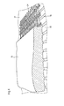
- a wall 31 for example.
- a reinforcing fabric 34 for example.
- the dry mixture is mixed with water, with the required amount of water depends mainly on the desired consistency; the water is partly converted into water of crystallization during setting; Any excess water may evaporate.
- the wet mass is foamed in a foaming device.
- a foaming device This can be connected downstream of a mixing device.
- the mass is stirred by a large number of passed elements until the dry mixture and the mixing water have distributed as homogeneously as possible.
- the mortar mixing and pumping device 1 can be charged via a feeding device 2 with a dry mixture or with the individual ingredients for the mortar. From there, the still dry mortar mixture then passes, for example, by means of a screw conveyor 3 in the actual mixing chamber or the actual mixing pot 4, where water is added to the extent required and this is then mixed with the dry mixture.
- the mixing process is carried out by a stirrer 5, which rotates about an approximately vertical axis 6 in the example shown, driven by an electric motor 7 on top of the Michhunt or the mixing pot 4. It is preferably a high-performance electric motor 7 with a rated power of 5 kW or above; between the electric motor 7 and the stirrer, moreover, a reduction gear may be provided so that the stirrer is indeed slowly, but vigorously rotated and thereby able to impose its motion on the tough mortar mass.
- the stirrer 5 is in Fig. 2 reproduced enlarged in a perspective view. It can be seen in addition to two mutually diametrically opposite with respect to the stirrer axis 6, frame-shaped, in particular U-shaped Stirrfort arrangementsn 8, 9, the webs 10 may in any case be partially at different axial heights, two more, in contrast, each offset by about 90 ° Stirrup 11, comprising, for example ., A respective radial impeller 12 and one of the respective wing level approximately vertically projecting, extending predominantly in the axial direction wing 13th
- both the radial webs 10 of the U-shaped stirring extensions 8, 9 and the radial stirring vanes 12 of the additional stirring extensions 11 are set in the direction of rotation with respect to the main plane perpendicularly penetrated by the stirrer axis 6;
- at least one stirring blade 12 of an additional stirring extension 11 - preferably the stirring blades 12 of additional stirring extensions 11 - employed in opposite directions than the radial webs 10 of the U-shaped Stirrfortans 8, 9.
- Fig. 1 further shows, there are above and below these Rrockfort instruments 8, 9, 11 further stirring blades 14, 15, which lie approximately within a perpendicular from the stirrer axis 6 enforced by the plane and extend approximately in the radial direction of the stirrer axis 6 away.
- the stirring blades 14, 15 are employed in the direction of rotation of the stirrer 5 relative to the main plane perpendicularly penetrated by the stirrer axis 6;
- at least one stirring blade 14 or possibly even two stirring blades 14 are employed in the opposite direction than the remaining stirring blades 15 of this propeller-like stirring blade arrangement 14, 15.
- stirring vanes 14, 15 may be present in the same number n as the stirring extensions 8, 9, 11 and offset from those by 180 ° / n in each case - that is, just about always centered between two adjacent stirring extensions 8, 9, 11 there too worry for swirling. All agitating blades 14, 15 and extensions 8, 9, 11 consist, for example, of 5 mm thick flat iron pieces, which, for example, are welded to the agitator axis 6.
- a screw shell pump 16 wherein the screw axis is preferably in a common alignment with the stirrer axis 6, and the form-fitting and thus rotationally joined to the stirrer axis 6 during assembly, so that the Screw conveyor of the screw shell pump 16 is also driven by the electric motor 7.
- the mortar delivery device 17 arranged downstream of the screw-shell pump 16. This is connected at the outlet of the mortar pump 16, if necessary with the interposition of an elbow 18, and consists essentially of a straight tube 19, on whose end a cover 20 which tapers the flow cross-section is screwed on. On this cover, in turn, connecting elements 21 are arranged for a hose, not shown, for example. Locking elements on the type of knee joints od. Like.
- the core or lance 22 consists of a solid metal rod with a diameter of at least 5 mm, preferably about 10 mm to 20 mm, and extends concentrically and coaxially within the tube 19, ideally over its entire, straight elongated section.
- the core or lance 22 is held in this central position by a further plate 24 at its upstream end, which may have approximately the same dimensions as the downstream metal plate 23, namely a rectangular shape with a transverse dimension to the soul or lance 22, which approximately the inner diameter of the tube 19 corresponds.
- the two holding plates 23, 24 may lie together with the longitudinal axis of the core or lance 22 in a common plane or be offset from each other, for example. At an angle of 90 °, relative to the longitudinal axis of the soul or lance 22nd
- the core or lance 22 carries a plurality of planar flow obstacles 25.
- These flow obstacles 25 are each bent from an originally round sheet metal blank, the diameter of this sheet metal blank approximately corresponding to the inner diameter of the tube 19.
- These blanks each have in the middle of a through-hole for passing through the soul or lance 22.
- they are bent or folded in such a way that two approximately congruent halves 26 result, wherein the bending line 27 extends in each case through the through-hole, thereby dividing the sheet metal blank into two equal halves 26.
- these two halves 26 are not parallel to each other, but diverge from one another at an angle which is preferably between about 30 ° and 60 °.
- a cross-section through such a flow annulus 25 can thus be described as V-shaped, with the two legs of the V corresponding to one half 26 of the obstacle 25, and the top of the V of the bending line 27.
- the flow obstacles 25 are oriented such that the bending lines 27 of successive flow obstacles 25 not parallel to each other velraufen, but around the longitudinal axis of the soul or lance 22 are rotated against each other, for example. At an angle of 90 °, as from Fig. 3 seen.
- successive flow obstacles 25 at a mutual distance, which is preferably in the order between the radius and the diameter of the tube 19. In these positions, the flow obstacles 25 are attached to the core or lance 22, preferably welded.
- the mortar flows through the pipe 19. In doing so, it is forced to flow around each of the flow obstacles 25, with the gradient of flow direction and velocity within the flow changing. This results in a fluctuating pressure distribution within the mortar composition with local negative pressure areas, whereby existing pores rupture and thus the pore content increases significantly.
- air supply openings 28, 29 are arranged in each case in the tube 19, but possibly also on the screw shell pump 16. These can either communicate with the atmospheric air pressure or be fed with compressed air. Moreover, in each case a check valve may be provided at these air supply openings 28, 29, which allows the ingress of air inwardly, on the other hand prevents the escape of air or mortar components.
- the cleaning compound 35 is conveyed to an outlet 30 without great pressure.
- a hose is connected to a local, downstream connection 30 of the pipe 19
- the mortar 35 which is offset to a greater extent with air pores, easily spills out there and can then be conveyed to a house wall 31 and used there for plastering, for example.
- the wall 31 On the wall 31, it can flow around a reinforcing fabric 34 there and fill the groove-shaped depressions 33 without the inner pores being able to close again.
- the plaster mass 35 is mechanically smoothed, for example. With a cleaning trowel, and finally hardens on the wall 31 from.
- inorganic substances in particular mineral compositions based on lime and / or gypsum and / or cement, as a two or three-component mixture, are generally non-combustible.
- these compositions can also be used for screed, furthermore for dry or wet mortar walls, or for processing into thermal insulation panels, etc.
- Further advantages of such mineral masses are that they are permeable and allow moisture to pass through, and that they are very easily applied and processed can, if necessary, in several layers up to total layer thicknesses in the order of, for example, 5 cm.
- the cured plaster 35 can be post-processed, for example. Provided with a water-repellent finish and / or painted.
- the mass 35 can be filled to facilitate adhesion during the wet state behind a wall mounted in front of the wall 31, for example.
- a distance of up to 20 centimeters for example, at a distance of 15 cm or less, and / or at a distance of 2 cm or more, preferably 4 cm or more, and / or at a distance of 6 to 12 cm, in particular at a distance of 8 to 10 cm. If the formwork is removed after curing, then the plaster layer 35 remains with a maximum smooth and even surface, or that has a defined structure in accordance with an inserted into the formwork structure die.
- a mass 35 according to the invention can also be filled into cavities of the brick 32 or other stones, for example limestone or cement blocks, etc., in order to improve heat and / or sound insulation properties.
- composition according to the invention 35 can also be processed into self-supporting components, in particular plates by not on a support structure, eg. A wall 31, hardens and thereby connects with that, but by, for example, without such a support structure hardens, for example on a flat, smooth base plate, for example of metal, from which it is subsequently released after curing.
- a support structure eg. A wall 31
- hardens for example on a flat, smooth base plate, for example of metal, from which it is subsequently released after curing.
- this can, for example, with webs of a sheet medium, for example. Paper, are pasted.
Applications Claiming Priority (2)
| Application Number | Priority Date | Filing Date | Title |
|---|---|---|---|
| DE202011108616U DE202011108616U1 (de) | 2011-12-05 | 2011-12-05 | Mörtelpumpe |
| DE102012020841A DE102012020841A1 (de) | 2011-12-05 | 2012-10-24 | Mineralschaum und Verfahren zur Herstellung desselben |
Publications (2)
| Publication Number | Publication Date |
|---|---|
| EP2602237A2 true EP2602237A2 (fr) | 2013-06-12 |
| EP2602237A3 EP2602237A3 (fr) | 2015-06-24 |
Family
ID=47500868
Family Applications (1)
| Application Number | Title | Priority Date | Filing Date |
|---|---|---|---|
| EP12008122.9A Pending EP2602237A3 (fr) | 2011-12-05 | 2012-12-05 | Mousse minérale, procédé de fabrication de celle-ci et dispositif d'exécution de ce procédé |
Country Status (2)
| Country | Link |
|---|---|
| EP (1) | EP2602237A3 (fr) |
| DE (1) | DE102012020841A1 (fr) |
Cited By (3)
| Publication number | Priority date | Publication date | Assignee | Title |
|---|---|---|---|---|
| EP2722319B1 (fr) | 2012-10-16 | 2019-07-03 | STO SE & Co. KGaA | Isolation phonique et/ou thermique et système d'isolation thermique |
| CN112892442A (zh) * | 2021-01-13 | 2021-06-04 | 吕佳丽 | 一种改性酯化反应釜 |
| CN113813872A (zh) * | 2021-08-27 | 2021-12-21 | 佛山市特赛化工设备有限公司 | 一种比例可调供料装置及混合机 |
Families Citing this family (4)
| Publication number | Priority date | Publication date | Assignee | Title |
|---|---|---|---|---|
| DE102014101704A1 (de) * | 2013-12-20 | 2015-06-25 | Interbran Systems Ag | Wärmedämmputz |
| DE202015100064U1 (de) * | 2015-01-08 | 2015-02-02 | Bundesrepublik Deutschland, Vertreten Durch Den Bundesminister Für Wirtschaft Und Energie, Dieser Vertreten Durch Den Präsidenten Der Bundesanstalt Für Materialforschung Und -Prüfung (Bam) | Betonmischung zur Herstellung eines Betonerzeugnisses zur Energiedissipation bei Stoßbeanspruchung |
| WO2020011354A1 (fr) | 2018-07-11 | 2020-01-16 | Wacker Chemie Ag | Mélange miscible à l'eau contenant des corps moulés en silice |
| WO2020038582A1 (fr) | 2018-08-23 | 2020-02-27 | Wacker Chemie Ag | Mélange pouvant se mélanger à de l'eau contenant des corps moulés d'acide silicique rendu hydrophobe et des agents mouillants |
Family Cites Families (4)
| Publication number | Priority date | Publication date | Assignee | Title |
|---|---|---|---|---|
| GB608276A (en) * | 1946-02-19 | 1948-09-13 | William Peter Webb | Improvements in machines for mixing concrete and the like |
| US3565647A (en) * | 1968-09-23 | 1971-02-23 | Jules Magder | Method for the manufacture of cellular foamed material |
| DE3241193A1 (de) * | 1982-11-08 | 1984-05-10 | Dietrich Dipl.-Ing. 6240 Königstein Maurer | Vorrichtung zum kontinuierlichen mischen von trockengut mit einer fluessigkeit und foerdern des mischgutes |
| AT509576B1 (de) * | 2010-03-04 | 2012-05-15 | Geolyth Mineral Technologie Gmbh | Mineralschaum |
-
2012
- 2012-10-24 DE DE102012020841A patent/DE102012020841A1/de active Pending
- 2012-12-05 EP EP12008122.9A patent/EP2602237A3/fr active Pending
Non-Patent Citations (1)
| Title |
|---|
| None |
Cited By (3)
| Publication number | Priority date | Publication date | Assignee | Title |
|---|---|---|---|---|
| EP2722319B1 (fr) | 2012-10-16 | 2019-07-03 | STO SE & Co. KGaA | Isolation phonique et/ou thermique et système d'isolation thermique |
| CN112892442A (zh) * | 2021-01-13 | 2021-06-04 | 吕佳丽 | 一种改性酯化反应釜 |
| CN113813872A (zh) * | 2021-08-27 | 2021-12-21 | 佛山市特赛化工设备有限公司 | 一种比例可调供料装置及混合机 |
Also Published As
| Publication number | Publication date |
|---|---|
| DE102012020841A1 (de) | 2013-06-06 |
| EP2602237A3 (fr) | 2015-06-24 |
Similar Documents
| Publication | Publication Date | Title |
|---|---|---|
| EP2602237A2 (fr) | Mousse minérale, procédé de fabrication de celle-ci et dispositif d'exécution de ce procédé | |
| AT509011B1 (de) | Mineralschaum | |
| WO2012034724A1 (fr) | Matériau de construction et élément d'un système de construction et procédé pour les fabriquer | |
| DE10211331B4 (de) | Verfahren zum Herstellen einer aerogelhaltigen Dämmschicht auf einer Außenwand eines Gebäudes | |
| EP2151531A2 (fr) | Bloc de maçonnerie pour isolation thermique | |
| EP1608603B1 (fr) | Beton leger et procede de fabrication associe | |
| DE1803381C3 (de) | Mischung für Isolierputz | |
| DE102006033061A1 (de) | Lärmschutzwerkstoff | |
| DE19962137A1 (de) | Schalungselement aus mineralischem Leichtstoff | |
| DE2822356A1 (de) | Verfahren zur herstellung eines formkoerpers | |
| EP2681171B1 (fr) | Plaque multicouche minérale et son procédé de production | |
| DE19848248C2 (de) | Dünnwandiges Bauteil aus hydraulisch erhärtetem Zementsteinmaterial sowie Verfahren zu seiner Herstellung | |
| EP2891752A1 (fr) | Corps de formage en matière légère et son procédé de fabrication et d'utilisation | |
| DE19644312A1 (de) | Wärme- und schalldämmende Integralleichtbetonkonstruktionen und Verfahren zu deren Herstellung und Transport | |
| AT515534A4 (de) | Schüttfähige Mischung zur Bildung einer thermischen Dämmschicht | |
| DE19854884A1 (de) | Verfahren zum Herstellen eines wenigstens zweischichtigen Außenwandelements und dadurch hergestelltes Außenwandelement | |
| DE102017129140A1 (de) | Verfahren zur Herstellung eines Bauelementes aus Schaumbeton und selbiges | |
| EP0568752A1 (fr) | Plâtre léger | |
| DE102015218759B3 (de) | Gips-Zement-Trockenmischung und daraus hergestellte Gebäudefertigteile | |
| EP0360858A1 (fr) | Agregat leger pour beton | |
| EP1108696A1 (fr) | Procédé pour la minéralisation de matières premières renouvables, utilisation des matières premières minéralisées pour la fabrication de béton et d'éléments et matières de construction et les éléments et matières de construction ainsi obtenues | |
| AT509244B1 (de) | Mineralische mehrschichtplatte und verfahren zur herstellung | |
| EP0781733B1 (fr) | Mortier léger et procédé pour sa fabrication | |
| DE10002662A1 (de) | Schalungselement aus mineralischem Leichtstoff | |
| DE202011108616U1 (de) | Mörtelpumpe |
Legal Events
| Date | Code | Title | Description |
|---|---|---|---|
| PUAI | Public reference made under article 153(3) epc to a published international application that has entered the european phase |
Free format text: ORIGINAL CODE: 0009012 |
|
| AK | Designated contracting states |
Kind code of ref document: A2 Designated state(s): AL AT BE BG CH CY CZ DE DK EE ES FI FR GB GR HR HU IE IS IT LI LT LU LV MC MK MT NL NO PL PT RO RS SE SI SK SM TR |
|
| AX | Request for extension of the european patent |
Extension state: BA ME |
|
| PUAL | Search report despatched |
Free format text: ORIGINAL CODE: 0009013 |
|
| AK | Designated contracting states |
Kind code of ref document: A3 Designated state(s): AL AT BE BG CH CY CZ DE DK EE ES FI FR GB GR HR HU IE IS IT LI LT LU LV MC MK MT NL NO PL PT RO RS SE SI SK SM TR |
|
| AX | Request for extension of the european patent |
Extension state: BA ME |
|
| RIC1 | Information provided on ipc code assigned before grant |
Ipc: C04B 38/10 20060101AFI20150519BHEP Ipc: B01F 7/00 20060101ALI20150519BHEP Ipc: B01F 3/12 20060101ALI20150519BHEP Ipc: B01F 5/06 20060101ALI20150519BHEP Ipc: B01F 7/18 20060101ALI20150519BHEP |
|
| RIN1 | Information on inventor provided before grant (corrected) |
Inventor name: GROPPWEIS, SEBASTIAN Inventor name: SCHARFE, FRIEDBERT Inventor name: WAGNER, HORST |
|
| 17P | Request for examination filed |
Effective date: 20151222 |
|
| RBV | Designated contracting states (corrected) |
Designated state(s): AL AT BE BG CH CY CZ DE DK EE ES FI FR GB GR HR HU IE IS IT LI LT LU LV MC MK MT NL NO PL PT RO RS SE SI SK SM TR |
|
| STAA | Information on the status of an ep patent application or granted ep patent |
Free format text: STATUS: EXAMINATION IS IN PROGRESS |
|
| 17Q | First examination report despatched |
Effective date: 20170213 |
|
| STAA | Information on the status of an ep patent application or granted ep patent |
Free format text: STATUS: EXAMINATION IS IN PROGRESS |