EP2602123A1 - Integrierte Nabenlageranordnung für das Rad eines Kraftfahrzeugs - Google Patents
Integrierte Nabenlageranordnung für das Rad eines Kraftfahrzeugs Download PDFInfo
- Publication number
- EP2602123A1 EP2602123A1 EP12194135.5A EP12194135A EP2602123A1 EP 2602123 A1 EP2602123 A1 EP 2602123A1 EP 12194135 A EP12194135 A EP 12194135A EP 2602123 A1 EP2602123 A1 EP 2602123A1
- Authority
- EP
- European Patent Office
- Prior art keywords
- hub
- flange
- axially
- assembly according
- assembly
- Prior art date
- Legal status (The legal status is an assumption and is not a legal conclusion. Google has not performed a legal analysis and makes no representation as to the accuracy of the status listed.)
- Granted
Links
- 238000005096 rolling process Methods 0.000 claims description 19
- 230000008878 coupling Effects 0.000 claims 1
- 238000010168 coupling process Methods 0.000 claims 1
- 238000005859 coupling reaction Methods 0.000 claims 1
- 230000008901 benefit Effects 0.000 description 4
- 230000036316 preload Effects 0.000 description 3
- 239000000725 suspension Substances 0.000 description 3
- 238000005553 drilling Methods 0.000 description 2
- 230000014509 gene expression Effects 0.000 description 2
- 238000003801 milling Methods 0.000 description 2
- 238000007789 sealing Methods 0.000 description 2
- 230000004323 axial length Effects 0.000 description 1
- 239000000356 contaminant Substances 0.000 description 1
- 230000001419 dependent effect Effects 0.000 description 1
- 239000000428 dust Substances 0.000 description 1
- 230000000694 effects Effects 0.000 description 1
- 239000011499 joint compound Substances 0.000 description 1
- 238000012986 modification Methods 0.000 description 1
- 230000004048 modification Effects 0.000 description 1
- 230000008092 positive effect Effects 0.000 description 1
- XLYOFNOQVPJJNP-UHFFFAOYSA-N water Substances O XLYOFNOQVPJJNP-UHFFFAOYSA-N 0.000 description 1
Images
Classifications
-
- B—PERFORMING OPERATIONS; TRANSPORTING
- B60—VEHICLES IN GENERAL
- B60B—VEHICLE WHEELS; CASTORS; AXLES FOR WHEELS OR CASTORS; INCREASING WHEEL ADHESION
- B60B27/00—Hubs
- B60B27/0005—Hubs with ball bearings
-
- B—PERFORMING OPERATIONS; TRANSPORTING
- B60—VEHICLES IN GENERAL
- B60B—VEHICLE WHEELS; CASTORS; AXLES FOR WHEELS OR CASTORS; INCREASING WHEEL ADHESION
- B60B27/00—Hubs
- B60B27/001—Hubs with roller-bearings
-
- B—PERFORMING OPERATIONS; TRANSPORTING
- B60—VEHICLES IN GENERAL
- B60B—VEHICLE WHEELS; CASTORS; AXLES FOR WHEELS OR CASTORS; INCREASING WHEEL ADHESION
- B60B27/00—Hubs
- B60B27/0015—Hubs for driven wheels
- B60B27/0021—Hubs for driven wheels characterised by torque transmission means from drive axle
- B60B27/0026—Hubs for driven wheels characterised by torque transmission means from drive axle of the radial type, e.g. splined key
-
- B—PERFORMING OPERATIONS; TRANSPORTING
- B60—VEHICLES IN GENERAL
- B60B—VEHICLE WHEELS; CASTORS; AXLES FOR WHEELS OR CASTORS; INCREASING WHEEL ADHESION
- B60B27/00—Hubs
- B60B27/0015—Hubs for driven wheels
- B60B27/0036—Hubs for driven wheels comprising homokinetic joints
- B60B27/0042—Hubs for driven wheels comprising homokinetic joints characterised by the fixation of the homokinetic joint to the hub
-
- B—PERFORMING OPERATIONS; TRANSPORTING
- B60—VEHICLES IN GENERAL
- B60B—VEHICLE WHEELS; CASTORS; AXLES FOR WHEELS OR CASTORS; INCREASING WHEEL ADHESION
- B60B27/00—Hubs
- B60B27/0078—Hubs characterised by the fixation of bearings
- B60B27/0084—Hubs characterised by the fixation of bearings caulking to fix inner race
-
- B—PERFORMING OPERATIONS; TRANSPORTING
- B60—VEHICLES IN GENERAL
- B60B—VEHICLE WHEELS; CASTORS; AXLES FOR WHEELS OR CASTORS; INCREASING WHEEL ADHESION
- B60B27/00—Hubs
- B60B27/0094—Hubs one or more of the bearing races are formed by the hub
-
- B—PERFORMING OPERATIONS; TRANSPORTING
- B60—VEHICLES IN GENERAL
- B60B—VEHICLE WHEELS; CASTORS; AXLES FOR WHEELS OR CASTORS; INCREASING WHEEL ADHESION
- B60B3/00—Disc wheels, i.e. wheels with load-supporting disc body
- B60B3/14—Attaching disc body to hub ; Wheel adapters
- B60B3/142—Attaching disc body to hub ; Wheel adapters by central locking nut
-
- F—MECHANICAL ENGINEERING; LIGHTING; HEATING; WEAPONS; BLASTING
- F16—ENGINEERING ELEMENTS AND UNITS; GENERAL MEASURES FOR PRODUCING AND MAINTAINING EFFECTIVE FUNCTIONING OF MACHINES OR INSTALLATIONS; THERMAL INSULATION IN GENERAL
- F16C—SHAFTS; FLEXIBLE SHAFTS; ELEMENTS OR CRANKSHAFT MECHANISMS; ROTARY BODIES OTHER THAN GEARING ELEMENTS; BEARINGS
- F16C35/00—Rigid support of bearing units; Housings, e.g. caps, covers
- F16C35/04—Rigid support of bearing units; Housings, e.g. caps, covers in the case of ball or roller bearings
- F16C35/06—Mounting or dismounting of ball or roller bearings; Fixing them onto shaft or in housing
- F16C35/063—Fixing them on the shaft
- F16C35/0635—Fixing them on the shaft the bore of the inner ring being of special non-cylindrical shape which co-operates with a complementary shape on the shaft, e.g. teeth, polygonal sections
-
- B—PERFORMING OPERATIONS; TRANSPORTING
- B60—VEHICLES IN GENERAL
- B60B—VEHICLE WHEELS; CASTORS; AXLES FOR WHEELS OR CASTORS; INCREASING WHEEL ADHESION
- B60B2310/00—Manufacturing methods
- B60B2310/30—Manufacturing methods joining
- B60B2310/305—Manufacturing methods joining by screwing
-
- B—PERFORMING OPERATIONS; TRANSPORTING
- B60—VEHICLES IN GENERAL
- B60B—VEHICLE WHEELS; CASTORS; AXLES FOR WHEELS OR CASTORS; INCREASING WHEEL ADHESION
- B60B2380/00—Bearings
- B60B2380/10—Type
- B60B2380/12—Ball bearings
-
- B—PERFORMING OPERATIONS; TRANSPORTING
- B60—VEHICLES IN GENERAL
- B60B—VEHICLE WHEELS; CASTORS; AXLES FOR WHEELS OR CASTORS; INCREASING WHEEL ADHESION
- B60B2900/00—Purpose of invention
- B60B2900/10—Reduction of
- B60B2900/113—Production or maintenance time
-
- B—PERFORMING OPERATIONS; TRANSPORTING
- B60—VEHICLES IN GENERAL
- B60B—VEHICLE WHEELS; CASTORS; AXLES FOR WHEELS OR CASTORS; INCREASING WHEEL ADHESION
- B60B2900/00—Purpose of invention
- B60B2900/50—Improvement of
- B60B2900/541—Servicing
-
- B—PERFORMING OPERATIONS; TRANSPORTING
- B60—VEHICLES IN GENERAL
- B60Y—INDEXING SCHEME RELATING TO ASPECTS CROSS-CUTTING VEHICLE TECHNOLOGY
- B60Y2200/00—Type of vehicle
- B60Y2200/10—Road Vehicles
- B60Y2200/11—Passenger cars; Automobiles
- B60Y2200/114—Racing vehicles, e.g. Formula one, Karts
-
- B—PERFORMING OPERATIONS; TRANSPORTING
- B60—VEHICLES IN GENERAL
- B60Y—INDEXING SCHEME RELATING TO ASPECTS CROSS-CUTTING VEHICLE TECHNOLOGY
- B60Y2410/00—Constructional features of vehicle sub-units
- B60Y2410/102—Shaft arrangements; Shaft supports, e.g. bearings
-
- F—MECHANICAL ENGINEERING; LIGHTING; HEATING; WEAPONS; BLASTING
- F16—ENGINEERING ELEMENTS AND UNITS; GENERAL MEASURES FOR PRODUCING AND MAINTAINING EFFECTIVE FUNCTIONING OF MACHINES OR INSTALLATIONS; THERMAL INSULATION IN GENERAL
- F16C—SHAFTS; FLEXIBLE SHAFTS; ELEMENTS OR CRANKSHAFT MECHANISMS; ROTARY BODIES OTHER THAN GEARING ELEMENTS; BEARINGS
- F16C19/00—Bearings with rolling contact, for exclusively rotary movement
- F16C19/02—Bearings with rolling contact, for exclusively rotary movement with bearing balls essentially of the same size in one or more circular rows
- F16C19/14—Bearings with rolling contact, for exclusively rotary movement with bearing balls essentially of the same size in one or more circular rows for both radial and axial load
- F16C19/18—Bearings with rolling contact, for exclusively rotary movement with bearing balls essentially of the same size in one or more circular rows for both radial and axial load with two or more rows of balls
- F16C19/181—Bearings with rolling contact, for exclusively rotary movement with bearing balls essentially of the same size in one or more circular rows for both radial and axial load with two or more rows of balls with angular contact
- F16C19/183—Bearings with rolling contact, for exclusively rotary movement with bearing balls essentially of the same size in one or more circular rows for both radial and axial load with two or more rows of balls with angular contact with two rows at opposite angles
- F16C19/184—Bearings with rolling contact, for exclusively rotary movement with bearing balls essentially of the same size in one or more circular rows for both radial and axial load with two or more rows of balls with angular contact with two rows at opposite angles in O-arrangement
- F16C19/186—Bearings with rolling contact, for exclusively rotary movement with bearing balls essentially of the same size in one or more circular rows for both radial and axial load with two or more rows of balls with angular contact with two rows at opposite angles in O-arrangement with three raceways provided integrally on parts other than race rings, e.g. third generation hubs
-
- F—MECHANICAL ENGINEERING; LIGHTING; HEATING; WEAPONS; BLASTING
- F16—ENGINEERING ELEMENTS AND UNITS; GENERAL MEASURES FOR PRODUCING AND MAINTAINING EFFECTIVE FUNCTIONING OF MACHINES OR INSTALLATIONS; THERMAL INSULATION IN GENERAL
- F16C—SHAFTS; FLEXIBLE SHAFTS; ELEMENTS OR CRANKSHAFT MECHANISMS; ROTARY BODIES OTHER THAN GEARING ELEMENTS; BEARINGS
- F16C19/00—Bearings with rolling contact, for exclusively rotary movement
- F16C19/50—Other types of ball or roller bearings
- F16C19/505—Other types of ball or roller bearings with the diameter of the rolling elements of one row differing from the diameter of those of another row
-
- F—MECHANICAL ENGINEERING; LIGHTING; HEATING; WEAPONS; BLASTING
- F16—ENGINEERING ELEMENTS AND UNITS; GENERAL MEASURES FOR PRODUCING AND MAINTAINING EFFECTIVE FUNCTIONING OF MACHINES OR INSTALLATIONS; THERMAL INSULATION IN GENERAL
- F16C—SHAFTS; FLEXIBLE SHAFTS; ELEMENTS OR CRANKSHAFT MECHANISMS; ROTARY BODIES OTHER THAN GEARING ELEMENTS; BEARINGS
- F16C2240/00—Specified values or numerical ranges of parameters; Relations between them
- F16C2240/40—Linear dimensions, e.g. length, radius, thickness, gap
- F16C2240/70—Diameters; Radii
- F16C2240/80—Pitch circle diameters [PCD]
-
- F—MECHANICAL ENGINEERING; LIGHTING; HEATING; WEAPONS; BLASTING
- F16—ENGINEERING ELEMENTS AND UNITS; GENERAL MEASURES FOR PRODUCING AND MAINTAINING EFFECTIVE FUNCTIONING OF MACHINES OR INSTALLATIONS; THERMAL INSULATION IN GENERAL
- F16C—SHAFTS; FLEXIBLE SHAFTS; ELEMENTS OR CRANKSHAFT MECHANISMS; ROTARY BODIES OTHER THAN GEARING ELEMENTS; BEARINGS
- F16C2326/00—Articles relating to transporting
- F16C2326/01—Parts of vehicles in general
- F16C2326/02—Wheel hubs or castors
Definitions
- the present invention relates to an integrated hub bearing for the wheel of a motor vehicle, and particularly to an integrated assembly of the type defined in the preamble of claim 1.
- US 7 104 695 B2 discloses an asymmetrical hub bearing assembly, comprising a hub with a flange extending radially outwardly from an axial end for mounting the wheel of a vehicle, an outer ring with axially spaced raceways, and a plurality of rolling elements arranged in two rows in the annular space between the outer ring and the hub.
- the pitch circle diameter of the row of rolling elements arranged at the axially outer side (outboard), adjacent to said flange, is greater than the diameter of the pitch circle of the rolling elements of the row on the axially inner side (inboard). Due to this arrangement, the distance between the pressure centers where the contact angle of the two bearing rows intercept the hub axis can be increased; this provides a higher camber stiffness.
- the outboard row intercepts the hub axis outboard of the hub flange, which balances the loads on the system more evenly between the inner and outer bearing rows.
- the outboard row can accommodate more rolling elements, and thus increase the load capacity of the bearing, at equal size of a symmetric unit.
- the asymmetric design allows to place the pressure center farther outboards than a symmetric unit, without having to increase the contact angle and without reducing the bearing capacity of the bearing in a radial direction.
- the asymmetrical arrangement finally, increases the load bearing capacity without requiring modifications to the suspension strut of the vehicle.
- the radial flange of the hub provides a number of holes to allow mounting of the vehicle wheel by means of bolts.
- the flange also has a flat radial surface, at the axially outer side, which defines a precise reference surface against which the brake disc and the wheel may rest.
- the hub also forms a centering annular projection which extends in the axially direction beyond the radial flange. This projection is designed to enable a preliminary support and centering of the wheel, before it is fixed, in a perfectly centered position, via the fastening bolts that are inserted through the holes of the flange.
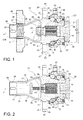
- a flanged hub bearing unit according to a first embodiment of the invention is indicated as a whole at 10.
- the assembly 10 serves to rotatably mount a wheel (not shown) to the suspension strut (not shown) of a vehicle, around a central axis of rotation x.
- terms and expressions indicating positions and directions such as “radial” and “axial” shall be construed as referring to the axis of rotation x of the bearing.
- Expressions such as “axially inner” and “axially outer” are referred to the mounted condition on the vehicle.
- the hub bearing assembly 10 is of the asymmetric type and includes a flanged hub 11 rotatable about the axis x, a flange 20 integral with the flanged hub 11 and transverse to the axis x, a stationary ring 13 arranged radially outside of the flanged hub 11 and provided with respective raceways 47, 48 axially spaced from one another, and two rows 14, 15 of rolling elements arranged within the raceways between the stationary ring 13 and the flanged hub 11.
- the rows 14, 15 have respective pitch circles C1, C2 with respective diameters D1, D2 of which the diameter D1 of the pitch circle C1 of the row 14 of the rolling elements has axially outer dimensions greater than the dimensions of the diameter of the pitch circle C2 of the row 15 of axially inner rolling elements.
- the hub 11 includes a radially inner tubular core 16, which integrally forms a radially inner raceway 17 for the row 14 of rolling elements arranged at the axially outer side (or “outboard” side), and an annular insert 12, which is fitted on the tubular core 16 and forms a radially inner raceway 18 for the row 15 of rolling elements arranged by the axially inner side (or “inboard” side).
- the rolling elements of the two rows 14, 15 are bearing balls, arranged between the stationary ring 13 and the flanged hub 11 according to the arrangement of a double row angular contact ball bearing.
- the tubular core 16 is angularly coupled to a constant velocity joint 30 provided with a bell 31 and a grooved shaft 32.
- the shaft 32 is directly inserted, through the tubular core 16, in a cylindrical cavity 45 with axial splines 46.
- the shaft 32 is angularly coupled to the core by means of an outer spline for transmitting a driving torque from the joint to the hub.
- the shaft 32 is axially locked to the hub by means of a connecting nut 33 that is screwed on a projecting threaded end 34 of the shaft 32 and abuts against a radial surface 28 of the hub.
- the nut 33 clamps the bell 31 against the annular insert 12 and also determines a preload to the hub-bearing assembly 10.
- the diameter of the pitch circle of the ball bearing 14 arranged at the outboard side is greater than the diameter of the pitch circle of the bearing balls 15 at the axially inner (inboard) side; the row of bearing balls 14 locates a center P1 of pressure on the x axis corresponding to the point where the lines of action of the forces, exchanged between the track 17 and each ball of the ball bearing 15, converge.
- An asymmetric arrangement of this kind is disclosed, for example, in US 7 104 695 B2 , which is herein incorporated by reference.
- the hub 11 forms a radially outwardly extending flange 20 which provides a flat radial surface 21, at the axially outer side, defining a flat and accurate radial surface of reference, against which the disc brake and the wheel (not shown) may rest.
- Formed in the flange 20 are lightening holes 22 circumferentially distributed uniformly, preferably equally spaced.
- the holes 22 are through holes which inwardly on a flat part 23 of the radial surface on the axially inner side of the flange, with the advantages set out herein after.
- the wheel is fastened to the hub by means of an axially extending tubular portion 19 that protrudes in the axially outer direction beyond the radial flange 20.
- the tubular portion 19 of the hub comprises:
- the tubular portion 19 is located at the axially outer side with respect to the flange 20, while the rows 14, 15 of rolling elements and the stationary ring 13 are on the opposite side, i.e. on the axially inner side with respect to the flange 20.
- the tubular portion 19 of the hub also comprises a further cylindrical end portion 38 provided with through holes 39 adapted to receive self-locking elements (not shown) of the single central threaded fastener 40.
- the axial length of the tubular portion 19 depends on the axial width of the wheel to be mounted.
- an axial distance d of an end portion of the internal thread 24 from the point P1 the overall stiffness of the entire assembly 10 can equally be set.
- the diameter of the pitch circle of the outboard row of balls 14 is greater than the diameter of the pitch circle of the inboard row of bearing balls 15, the distance d being less than 45 mm.
- the thread 24 is formed on the outer cylindrical surface 37 of the tubular portion 19, and the fastener 40 has therefore a corresponding thread 41 formed in its central hole.
- the thread 24a is formed on the inner cylindrical surface of the axial cavity of the tubular portion 19, and a single fastener (not shown), similar to the fastener 40, has a stem with an outer thread.
- a single fastener (not shown), similar to the fastener 40, has a stem with an outer thread.
- the outer ring 13 provides, in a per se known manner, a radially outer flange 25 for fastening to a suspension standard of the vehicle.
- Two conventional sealing devices 26, 27, in this example of the cassette type, are provided at the opposite axial ends of the outer ring 13, one on the outboard side between the outer ring 13 and the hub 11, and the other on the inboard side between the outer ring 13 and the annular insert 12.
- the annular insert 12 is not axially locked during assembly of the constant velocity joint 30, but is axially locked by means of an end edge 44 of the hub, which is cold formed, preferably by orbital rolling. In this way, the axial preload of the assembly is made completely independent of the assembly step preformed afterwards.
- the constant velocity joint 30 is axially locked to the hub by means of a screw connection 42 which engages in a threaded hole 43 of the shaft 32 and abuts against a radial surface 28 of the hub, thus tightening the bell 31 against the rolled edge 44 of the hub.
- the assembly of the constant velocity joint is dispensed with having to apply an axial preload to the bearing.
- This allows the use of a screw connection 42 having an outer size smaller than the outer size of the nut 33 described above, with the immediate advantage of being able to reduce the sizes, preferably the diametrical ones, of the entire tubular portion 19 by at least 30% with consequent benefits in terms of weight and bulk reduction without, however, affecting rigidity and performance.
- the hub bearing assembly has a greater stiffness. As the vehicle runs along a bend, the greater above-mentioned stiffness implies a minor deflection of the flange in the area where this is joined to the tubular core hub. This allows to reduce significantly the fillet radius 29 between the flange 20 and the tubular core 16, so that the radial surface 23 of the axially inner side of the flange may extend flat to a greater extent as compared to the prior art; in other words, the flat part of the surface 23 extends closer to the tubular core of the hub and the central axis x of the assembly.
- the flat surface 23 allows to conveniently form the through lightening holes 22 directly and simply with a single drilling operation, making them of the required diameter. Otherwise, a conventional, large fillet radius would require to form the lightening holes through a first drilling step to make small holes having a smaller diameter than the final diameter required, and a second, expensive milling operation in case the lightening holes 22 should reach diameters equal to those as described herein.
- the significant reduction of the radius of the fillet 29 between the flange 20 and the tubular core 16 does not only have a positive effect on the greater extension of the radial surface 23 on the axially inner side of the flange 20, but also on a greater extension of an outer cylindrical surface 16a of the tubular core 16, immediately adjacent to the flange 20.
- the portion of the cylindrical surface 16a extends closer to the flange 20 allowing, therefore, to fix the outboard side sealing device 26 in a position immediately adjacent to the flange 20, and, also, to obtain a greater degree of axial compactness of the assembly 10, which results in bringing the flange 25 axially closer to the flange 20.
Landscapes
- Engineering & Computer Science (AREA)
- Mechanical Engineering (AREA)
- General Engineering & Computer Science (AREA)
- Rolling Contact Bearings (AREA)
Applications Claiming Priority (1)
| Application Number | Priority Date | Filing Date | Title |
|---|---|---|---|
| IT001127A ITTO20111127A1 (it) | 2011-12-09 | 2011-12-09 | Gruppo integrato cuscinetto-mozzo per la ruota di un veicolo a motore |
Publications (2)
| Publication Number | Publication Date |
|---|---|
| EP2602123A1 true EP2602123A1 (de) | 2013-06-12 |
| EP2602123B1 EP2602123B1 (de) | 2021-05-26 |
Family
ID=45561028
Family Applications (1)
| Application Number | Title | Priority Date | Filing Date |
|---|---|---|---|
| EP12194135.5A Active EP2602123B1 (de) | 2011-12-09 | 2012-11-23 | Integrierte Nabenlageranordnung für das Rad eines Kraftfahrzeugs |
Country Status (3)
| Country | Link |
|---|---|
| US (1) | US9259962B2 (de) |
| EP (1) | EP2602123B1 (de) |
| IT (1) | ITTO20111127A1 (de) |
Cited By (10)
| Publication number | Priority date | Publication date | Assignee | Title |
|---|---|---|---|---|
| EP2965922A1 (de) | 2014-07-11 | 2016-01-13 | Aktiebolaget SKF | Geflanschte nabe-lager-einheit |
| DE102016207219A1 (de) | 2015-04-29 | 2016-11-03 | Aktiebolaget Skf | Montagemethode für eine Nabenlagerungseinheit |
| DE102016207218A1 (de) | 2015-04-29 | 2016-11-03 | Aktiebolaget Skf | Methode zur Vorspannung einer Nabenlagereinheit |
| DE102016207215A1 (de) | 2015-04-29 | 2016-11-10 | Aktiebolaget Skf | Montageverfahren einer Nabenlagereinheit |
| EP2915683A4 (de) * | 2012-10-30 | 2017-03-01 | NTN Corporation | Lager für ein rad und lagervorrichtung für ein rad |
| DE102017205487A1 (de) | 2016-04-05 | 2017-10-05 | Aktiebolaget Skf | Radlagereinheit ausgelegt für eine Befestigung an dem Achsschenkel einer Aufhängung |
| DE102017205537A1 (de) | 2016-04-05 | 2017-10-05 | Aktiebolaget Skf | Radlagereinheit mit Rotornabe |
| CN108146144A (zh) * | 2017-08-28 | 2018-06-12 | 北京理工大学 | 一种用于电动轮的轮毂组件、电动轮及车辆 |
| CN108146145A (zh) * | 2017-08-28 | 2018-06-12 | 北京理工大学 | 一种具有大变速比行星减速器的电动轮及车辆 |
| DE102019204985A1 (de) | 2018-04-20 | 2019-10-24 | Aktiebolaget Skf | Flanschradnabeneinheit und herstellungsverfahren |
Families Citing this family (3)
| Publication number | Priority date | Publication date | Assignee | Title |
|---|---|---|---|---|
| WO2017179400A1 (ja) * | 2016-04-12 | 2017-10-19 | 日本精工株式会社 | ハブユニット軸受 |
| DE112020001904T5 (de) * | 2019-04-13 | 2022-01-05 | Iljin Global Co., Ltd. | Radlageranordnung |
| DE102020209285A1 (de) * | 2019-08-01 | 2021-02-04 | Aktiebolaget Skf | Radlager |
Citations (7)
| Publication number | Priority date | Publication date | Assignee | Title |
|---|---|---|---|---|
| US4299425A (en) * | 1978-04-27 | 1981-11-10 | Daimler-Benz Aktiengesellschaft | Central locking mechanism for web disk wheels |
| JPH03262702A (ja) * | 1990-03-12 | 1991-11-22 | Nissan Motor Co Ltd | 被駆動輪のセンターロック式アクスル構造 |
| US5636905A (en) * | 1993-05-07 | 1997-06-10 | Pagacz; Zbigniew L. | System for central fastening a wheel to a vehicle |
| US7104695B2 (en) | 2003-10-14 | 2006-09-12 | Aktiebolaget Skf | Asymmetric hub assembly |
| US20090232435A1 (en) * | 2006-11-14 | 2009-09-17 | Ntn Corporation | Wheel Bearing Apparatus For A Vehicle |
| DE102011011005A1 (de) * | 2011-02-11 | 2011-09-01 | Daimler Ag | Radsicherungssystem |
| EP2380750A1 (de) * | 2010-04-20 | 2011-10-26 | Aktiebolaget SKF | Radnabenanordnung mit Wälzkörpern in zwei Reihen |
Family Cites Families (12)
| Publication number | Priority date | Publication date | Assignee | Title |
|---|---|---|---|---|
| US1206889A (en) * | 1916-05-29 | 1916-12-05 | Thomas E Murray | Hub for metal vehicle-wheels. |
| US2173043A (en) * | 1935-10-18 | 1939-09-12 | William Herbert Jordan | Detachable wheel for vehicles |
| US4354711A (en) * | 1980-04-21 | 1982-10-19 | Kelsey-Hayes Co. | Vehicle wheel assembly |
| GB2264089B (en) * | 1992-02-07 | 1995-03-29 | Masakazu Hayashi | Center lock device for automobile wheels |
| CA2169842C (en) * | 1993-08-18 | 2005-01-04 | Gian Antonio Gandellini | Light alloy wheel assembly for an automobile |
| US5901818A (en) * | 1995-05-16 | 1999-05-11 | Martino; Gerald | Brake rotors with heat-resistant ceramic coatings |
| ES2183934T3 (es) * | 1996-02-28 | 2003-04-01 | Toora S P A | Conjunto de rueda de aleacion ligera de una sola tuerca para vehiculo automovil. |
| US5820224A (en) * | 1997-02-19 | 1998-10-13 | L.A. Wire Wheel, Inc. | Motor vehicle wheel and wheel support assembly with knock-off nut |
| JP3869202B2 (ja) * | 2000-10-25 | 2007-01-17 | 株式会社ジェイテクト | 車両用ハブユニット |
| JP4044388B2 (ja) * | 2002-08-05 | 2008-02-06 | Ntn株式会社 | 駆動車輪用軸受装置 |
| JP5288821B2 (ja) * | 2008-02-13 | 2013-09-11 | Ntn株式会社 | 車輪用軸受装置 |
| JP2010013039A (ja) * | 2008-07-07 | 2010-01-21 | Nsk Ltd | 車輪支持用転がり軸受ユニット及びその製造方法 |
-
2011
- 2011-12-09 IT IT001127A patent/ITTO20111127A1/it unknown
-
2012
- 2012-11-23 EP EP12194135.5A patent/EP2602123B1/de active Active
- 2012-12-03 US US13/691,906 patent/US9259962B2/en active Active
Patent Citations (9)
| Publication number | Priority date | Publication date | Assignee | Title |
|---|---|---|---|---|
| US4299425A (en) * | 1978-04-27 | 1981-11-10 | Daimler-Benz Aktiengesellschaft | Central locking mechanism for web disk wheels |
| JPH03262702A (ja) * | 1990-03-12 | 1991-11-22 | Nissan Motor Co Ltd | 被駆動輪のセンターロック式アクスル構造 |
| US5636905A (en) * | 1993-05-07 | 1997-06-10 | Pagacz; Zbigniew L. | System for central fastening a wheel to a vehicle |
| US7104695B2 (en) | 2003-10-14 | 2006-09-12 | Aktiebolaget Skf | Asymmetric hub assembly |
| US7104695C1 (de) | 2003-10-14 | 2008-11-11 | ||
| US7104695C2 (de) | 2003-10-14 | 2011-08-30 | ||
| US20090232435A1 (en) * | 2006-11-14 | 2009-09-17 | Ntn Corporation | Wheel Bearing Apparatus For A Vehicle |
| EP2380750A1 (de) * | 2010-04-20 | 2011-10-26 | Aktiebolaget SKF | Radnabenanordnung mit Wälzkörpern in zwei Reihen |
| DE102011011005A1 (de) * | 2011-02-11 | 2011-09-01 | Daimler Ag | Radsicherungssystem |
Cited By (22)
| Publication number | Priority date | Publication date | Assignee | Title |
|---|---|---|---|---|
| EP2915683A4 (de) * | 2012-10-30 | 2017-03-01 | NTN Corporation | Lager für ein rad und lagervorrichtung für ein rad |
| US9493035B2 (en) | 2014-07-11 | 2016-11-15 | Aktiebolaget Skf | Flanged hub-bearing unit |
| CN105257692A (zh) * | 2014-07-11 | 2016-01-20 | Skf公司 | 带凸缘的毂轴承单元 |
| EP2965922A1 (de) | 2014-07-11 | 2016-01-13 | Aktiebolaget SKF | Geflanschte nabe-lager-einheit |
| US9897138B2 (en) | 2015-04-29 | 2018-02-20 | Aktiebolaget Skf | Method for preloading a hub bearing unit |
| DE102016207219A1 (de) | 2015-04-29 | 2016-11-03 | Aktiebolaget Skf | Montagemethode für eine Nabenlagerungseinheit |
| DE102016207218A1 (de) | 2015-04-29 | 2016-11-03 | Aktiebolaget Skf | Methode zur Vorspannung einer Nabenlagereinheit |
| DE102016207215A1 (de) | 2015-04-29 | 2016-11-10 | Aktiebolaget Skf | Montageverfahren einer Nabenlagereinheit |
| US9903417B2 (en) | 2015-04-29 | 2018-02-27 | Aktiebolaget Skf | Assembly procedure of a bearing unit—HUB flange |
| US9841058B2 (en) | 2015-04-29 | 2017-12-12 | Aktiebolaget Skf | Assembly procedure of a bearing unit—hub flange |
| US10563693B2 (en) | 2016-04-05 | 2020-02-18 | Aktiebolaget Skf | Hub-bearing unit configured for mounting on the knuckle of a suspension |
| DE102017205537A1 (de) | 2016-04-05 | 2017-10-05 | Aktiebolaget Skf | Radlagereinheit mit Rotornabe |
| US10369840B2 (en) | 2016-04-05 | 2019-08-06 | Aktiebolaget Skf | Hub-bearing unit with rotor hub |
| DE102017205487A1 (de) | 2016-04-05 | 2017-10-05 | Aktiebolaget Skf | Radlagereinheit ausgelegt für eine Befestigung an dem Achsschenkel einer Aufhängung |
| CN108146144A (zh) * | 2017-08-28 | 2018-06-12 | 北京理工大学 | 一种用于电动轮的轮毂组件、电动轮及车辆 |
| CN108146145A (zh) * | 2017-08-28 | 2018-06-12 | 北京理工大学 | 一种具有大变速比行星减速器的电动轮及车辆 |
| CN108146144B (zh) * | 2017-08-28 | 2020-08-18 | 北京理工大学 | 一种用于电动轮的轮毂组件、电动轮及车辆 |
| CN108146145B (zh) * | 2017-08-28 | 2020-08-18 | 北京理工大学 | 一种具有大变速比行星减速器的电动轮及车辆 |
| DE102019204985A1 (de) | 2018-04-20 | 2019-10-24 | Aktiebolaget Skf | Flanschradnabeneinheit und herstellungsverfahren |
| CN110385941A (zh) * | 2018-04-20 | 2019-10-29 | 斯凯孚公司 | 带凸缘的车轮轮毂单元和组装方法 |
| US10948021B2 (en) | 2018-04-20 | 2021-03-16 | Aktiebolaget Skf | Flanged wheel hub unit and assembly method |
| CN110385941B (zh) * | 2018-04-20 | 2024-05-28 | 斯凯孚公司 | 带凸缘的车轮轮毂单元和组装方法 |
Also Published As
| Publication number | Publication date |
|---|---|
| US9259962B2 (en) | 2016-02-16 |
| ITTO20111127A1 (it) | 2013-06-10 |
| US20130147258A1 (en) | 2013-06-13 |
| EP2602123B1 (de) | 2021-05-26 |
Similar Documents
| Publication | Publication Date | Title |
|---|---|---|
| EP2602123B1 (de) | Integrierte Nabenlageranordnung für das Rad eines Kraftfahrzeugs | |
| US8025579B2 (en) | Wheel support apparatus | |
| US7255482B2 (en) | Bearing apparatus for a driving wheel of vehicle | |
| EP1939471B1 (de) | Lagervorrichtung für rad | |
| US8465211B2 (en) | Compact wheel end and corner module | |
| JP5974437B2 (ja) | 車輪支持装置 | |
| EP2965922B1 (de) | Geflanschte nabe-lager-einheit | |
| JP2013047056A5 (de) | ||
| CN115003925A (zh) | 机动车辆车轮组件 | |
| US8002640B2 (en) | Wheel hub/universal joint assembly with end teeth and wheel bearing | |
| US20130292996A1 (en) | Wheel rolling bearing unit | |
| JP2841333B2 (ja) | 転がり軸受 | |
| US9694627B2 (en) | Hub-bearing having a light alloy rotor-hub | |
| EP2957432B1 (de) | Nabenlager mit einer leichtmetalllegierungs-rotornabe | |
| US20030063827A1 (en) | Compact hub assembly for automotive vehicles | |
| JP5549386B2 (ja) | 車輪用軸受装置 | |
| EP2623334B1 (de) | Radstützvorrichtung | |
| US20240159270A1 (en) | Integrated hub bearing unit | |
| US11420470B2 (en) | Wheel bearing | |
| CN118386727A (zh) | 机动车辆车轮组件 | |
| JP2010069926A (ja) | 駆動輪支持用ハブユニット | |
| KR20200120564A (ko) | 휠베어링 조립체 | |
| CN117597241A (zh) | 车轮用轴承装置 | |
| KR20210083431A (ko) | 허브 일체형 등속조인트 장치 | |
| JP2008138718A (ja) | 車輪用転がり軸受装置 |
Legal Events
| Date | Code | Title | Description |
|---|---|---|---|
| PUAI | Public reference made under article 153(3) epc to a published international application that has entered the european phase |
Free format text: ORIGINAL CODE: 0009012 |
|
| AK | Designated contracting states |
Kind code of ref document: A1 Designated state(s): AL AT BE BG CH CY CZ DE DK EE ES FI FR GB GR HR HU IE IS IT LI LT LU LV MC MK MT NL NO PL PT RO RS SE SI SK SM TR |
|
| AX | Request for extension of the european patent |
Extension state: BA ME |
|
| 17P | Request for examination filed |
Effective date: 20131211 |
|
| RBV | Designated contracting states (corrected) |
Designated state(s): AL AT BE BG CH CY CZ DE DK EE ES FI FR GB GR HR HU IE IS IT LI LT LU LV MC MK MT NL NO PL PT RO RS SE SI SK SM TR |
|
| STAA | Information on the status of an ep patent application or granted ep patent |
Free format text: STATUS: EXAMINATION IS IN PROGRESS |
|
| 17Q | First examination report despatched |
Effective date: 20190402 |
|
| GRAP | Despatch of communication of intention to grant a patent |
Free format text: ORIGINAL CODE: EPIDOSNIGR1 |
|
| STAA | Information on the status of an ep patent application or granted ep patent |
Free format text: STATUS: GRANT OF PATENT IS INTENDED |
|
| INTG | Intention to grant announced |
Effective date: 20201214 |
|
| GRAS | Grant fee paid |
Free format text: ORIGINAL CODE: EPIDOSNIGR3 |
|
| GRAA | (expected) grant |
Free format text: ORIGINAL CODE: 0009210 |
|
| STAA | Information on the status of an ep patent application or granted ep patent |
Free format text: STATUS: THE PATENT HAS BEEN GRANTED |
|
| AK | Designated contracting states |
Kind code of ref document: B1 Designated state(s): AL AT BE BG CH CY CZ DE DK EE ES FI FR GB GR HR HU IE IS IT LI LT LU LV MC MK MT NL NO PL PT RO RS SE SI SK SM TR |
|
| REG | Reference to a national code |
Ref country code: GB Ref legal event code: FG4D |
|
| REG | Reference to a national code |
Ref country code: CH Ref legal event code: EP |
|
| REG | Reference to a national code |
Ref country code: AT Ref legal event code: REF Ref document number: 1395837 Country of ref document: AT Kind code of ref document: T Effective date: 20210615 |
|
| REG | Reference to a national code |
Ref country code: DE Ref legal event code: R096 Ref document number: 602012075664 Country of ref document: DE |
|
| REG | Reference to a national code |
Ref country code: IE Ref legal event code: FG4D |
|
| REG | Reference to a national code |
Ref country code: LT Ref legal event code: MG9D |
|
| REG | Reference to a national code |
Ref country code: AT Ref legal event code: MK05 Ref document number: 1395837 Country of ref document: AT Kind code of ref document: T Effective date: 20210526 |
|
| PG25 | Lapsed in a contracting state [announced via postgrant information from national office to epo] |
Ref country code: FI Free format text: LAPSE BECAUSE OF FAILURE TO SUBMIT A TRANSLATION OF THE DESCRIPTION OR TO PAY THE FEE WITHIN THE PRESCRIBED TIME-LIMIT Effective date: 20210526 Ref country code: LT Free format text: LAPSE BECAUSE OF FAILURE TO SUBMIT A TRANSLATION OF THE DESCRIPTION OR TO PAY THE FEE WITHIN THE PRESCRIBED TIME-LIMIT Effective date: 20210526 Ref country code: HR Free format text: LAPSE BECAUSE OF FAILURE TO SUBMIT A TRANSLATION OF THE DESCRIPTION OR TO PAY THE FEE WITHIN THE PRESCRIBED TIME-LIMIT Effective date: 20210526 Ref country code: BG Free format text: LAPSE BECAUSE OF FAILURE TO SUBMIT A TRANSLATION OF THE DESCRIPTION OR TO PAY THE FEE WITHIN THE PRESCRIBED TIME-LIMIT Effective date: 20210826 Ref country code: AT Free format text: LAPSE BECAUSE OF FAILURE TO SUBMIT A TRANSLATION OF THE DESCRIPTION OR TO PAY THE FEE WITHIN THE PRESCRIBED TIME-LIMIT Effective date: 20210526 |
|
| REG | Reference to a national code |
Ref country code: NL Ref legal event code: MP Effective date: 20210526 |
|
| PG25 | Lapsed in a contracting state [announced via postgrant information from national office to epo] |
Ref country code: PL Free format text: LAPSE BECAUSE OF FAILURE TO SUBMIT A TRANSLATION OF THE DESCRIPTION OR TO PAY THE FEE WITHIN THE PRESCRIBED TIME-LIMIT Effective date: 20210526 Ref country code: PT Free format text: LAPSE BECAUSE OF FAILURE TO SUBMIT A TRANSLATION OF THE DESCRIPTION OR TO PAY THE FEE WITHIN THE PRESCRIBED TIME-LIMIT Effective date: 20210927 Ref country code: NO Free format text: LAPSE BECAUSE OF FAILURE TO SUBMIT A TRANSLATION OF THE DESCRIPTION OR TO PAY THE FEE WITHIN THE PRESCRIBED TIME-LIMIT Effective date: 20210826 Ref country code: GR Free format text: LAPSE BECAUSE OF FAILURE TO SUBMIT A TRANSLATION OF THE DESCRIPTION OR TO PAY THE FEE WITHIN THE PRESCRIBED TIME-LIMIT Effective date: 20210827 Ref country code: LV Free format text: LAPSE BECAUSE OF FAILURE TO SUBMIT A TRANSLATION OF THE DESCRIPTION OR TO PAY THE FEE WITHIN THE PRESCRIBED TIME-LIMIT Effective date: 20210526 Ref country code: IS Free format text: LAPSE BECAUSE OF FAILURE TO SUBMIT A TRANSLATION OF THE DESCRIPTION OR TO PAY THE FEE WITHIN THE PRESCRIBED TIME-LIMIT Effective date: 20210926 Ref country code: SE Free format text: LAPSE BECAUSE OF FAILURE TO SUBMIT A TRANSLATION OF THE DESCRIPTION OR TO PAY THE FEE WITHIN THE PRESCRIBED TIME-LIMIT Effective date: 20210526 Ref country code: RS Free format text: LAPSE BECAUSE OF FAILURE TO SUBMIT A TRANSLATION OF THE DESCRIPTION OR TO PAY THE FEE WITHIN THE PRESCRIBED TIME-LIMIT Effective date: 20210526 |
|
| PG25 | Lapsed in a contracting state [announced via postgrant information from national office to epo] |
Ref country code: NL Free format text: LAPSE BECAUSE OF FAILURE TO SUBMIT A TRANSLATION OF THE DESCRIPTION OR TO PAY THE FEE WITHIN THE PRESCRIBED TIME-LIMIT Effective date: 20210526 |
|
| PG25 | Lapsed in a contracting state [announced via postgrant information from national office to epo] |
Ref country code: ES Free format text: LAPSE BECAUSE OF FAILURE TO SUBMIT A TRANSLATION OF THE DESCRIPTION OR TO PAY THE FEE WITHIN THE PRESCRIBED TIME-LIMIT Effective date: 20210526 Ref country code: RO Free format text: LAPSE BECAUSE OF FAILURE TO SUBMIT A TRANSLATION OF THE DESCRIPTION OR TO PAY THE FEE WITHIN THE PRESCRIBED TIME-LIMIT Effective date: 20210526 Ref country code: SK Free format text: LAPSE BECAUSE OF FAILURE TO SUBMIT A TRANSLATION OF THE DESCRIPTION OR TO PAY THE FEE WITHIN THE PRESCRIBED TIME-LIMIT Effective date: 20210526 Ref country code: SM Free format text: LAPSE BECAUSE OF FAILURE TO SUBMIT A TRANSLATION OF THE DESCRIPTION OR TO PAY THE FEE WITHIN THE PRESCRIBED TIME-LIMIT Effective date: 20210526 Ref country code: CZ Free format text: LAPSE BECAUSE OF FAILURE TO SUBMIT A TRANSLATION OF THE DESCRIPTION OR TO PAY THE FEE WITHIN THE PRESCRIBED TIME-LIMIT Effective date: 20210526 Ref country code: DK Free format text: LAPSE BECAUSE OF FAILURE TO SUBMIT A TRANSLATION OF THE DESCRIPTION OR TO PAY THE FEE WITHIN THE PRESCRIBED TIME-LIMIT Effective date: 20210526 Ref country code: EE Free format text: LAPSE BECAUSE OF FAILURE TO SUBMIT A TRANSLATION OF THE DESCRIPTION OR TO PAY THE FEE WITHIN THE PRESCRIBED TIME-LIMIT Effective date: 20210526 |
|
| REG | Reference to a national code |
Ref country code: DE Ref legal event code: R097 Ref document number: 602012075664 Country of ref document: DE |
|
| PLBE | No opposition filed within time limit |
Free format text: ORIGINAL CODE: 0009261 |
|
| STAA | Information on the status of an ep patent application or granted ep patent |
Free format text: STATUS: NO OPPOSITION FILED WITHIN TIME LIMIT |
|
| 26N | No opposition filed |
Effective date: 20220301 |
|
| PG25 | Lapsed in a contracting state [announced via postgrant information from national office to epo] |
Ref country code: IS Free format text: LAPSE BECAUSE OF FAILURE TO SUBMIT A TRANSLATION OF THE DESCRIPTION OR TO PAY THE FEE WITHIN THE PRESCRIBED TIME-LIMIT Effective date: 20210926 Ref country code: AL Free format text: LAPSE BECAUSE OF FAILURE TO SUBMIT A TRANSLATION OF THE DESCRIPTION OR TO PAY THE FEE WITHIN THE PRESCRIBED TIME-LIMIT Effective date: 20210526 |
|
| PG25 | Lapsed in a contracting state [announced via postgrant information from national office to epo] |
Ref country code: MC Free format text: LAPSE BECAUSE OF FAILURE TO SUBMIT A TRANSLATION OF THE DESCRIPTION OR TO PAY THE FEE WITHIN THE PRESCRIBED TIME-LIMIT Effective date: 20210526 |
|
| REG | Reference to a national code |
Ref country code: CH Ref legal event code: PL |
|
| GBPC | Gb: european patent ceased through non-payment of renewal fee |
Effective date: 20211123 |
|
| PG25 | Lapsed in a contracting state [announced via postgrant information from national office to epo] |
Ref country code: LU Free format text: LAPSE BECAUSE OF NON-PAYMENT OF DUE FEES Effective date: 20211123 Ref country code: IT Free format text: LAPSE BECAUSE OF FAILURE TO SUBMIT A TRANSLATION OF THE DESCRIPTION OR TO PAY THE FEE WITHIN THE PRESCRIBED TIME-LIMIT Effective date: 20210526 Ref country code: BE Free format text: LAPSE BECAUSE OF NON-PAYMENT OF DUE FEES Effective date: 20211130 |
|
| REG | Reference to a national code |
Ref country code: BE Ref legal event code: MM Effective date: 20211130 |
|
| PG25 | Lapsed in a contracting state [announced via postgrant information from national office to epo] |
Ref country code: LI Free format text: LAPSE BECAUSE OF NON-PAYMENT OF DUE FEES Effective date: 20211130 Ref country code: CH Free format text: LAPSE BECAUSE OF NON-PAYMENT OF DUE FEES Effective date: 20211130 |
|
| PG25 | Lapsed in a contracting state [announced via postgrant information from national office to epo] |
Ref country code: IE Free format text: LAPSE BECAUSE OF NON-PAYMENT OF DUE FEES Effective date: 20211123 Ref country code: GB Free format text: LAPSE BECAUSE OF NON-PAYMENT OF DUE FEES Effective date: 20211123 |
|
| PG25 | Lapsed in a contracting state [announced via postgrant information from national office to epo] |
Ref country code: FR Free format text: LAPSE BECAUSE OF NON-PAYMENT OF DUE FEES Effective date: 20211130 |
|
| PG25 | Lapsed in a contracting state [announced via postgrant information from national office to epo] |
Ref country code: HU Free format text: LAPSE BECAUSE OF FAILURE TO SUBMIT A TRANSLATION OF THE DESCRIPTION OR TO PAY THE FEE WITHIN THE PRESCRIBED TIME-LIMIT; INVALID AB INITIO Effective date: 20121123 Ref country code: CY Free format text: LAPSE BECAUSE OF FAILURE TO SUBMIT A TRANSLATION OF THE DESCRIPTION OR TO PAY THE FEE WITHIN THE PRESCRIBED TIME-LIMIT Effective date: 20210526 |
|
| P01 | Opt-out of the competence of the unified patent court (upc) registered |
Effective date: 20230513 |
|
| PGFP | Annual fee paid to national office [announced via postgrant information from national office to epo] |
Ref country code: DE Payment date: 20231127 Year of fee payment: 12 |
|
| PG25 | Lapsed in a contracting state [announced via postgrant information from national office to epo] |
Ref country code: MK Free format text: LAPSE BECAUSE OF FAILURE TO SUBMIT A TRANSLATION OF THE DESCRIPTION OR TO PAY THE FEE WITHIN THE PRESCRIBED TIME-LIMIT Effective date: 20210526 |
|
| PG25 | Lapsed in a contracting state [announced via postgrant information from national office to epo] |
Ref country code: TR Free format text: LAPSE BECAUSE OF FAILURE TO SUBMIT A TRANSLATION OF THE DESCRIPTION OR TO PAY THE FEE WITHIN THE PRESCRIBED TIME-LIMIT Effective date: 20210526 |
|
| PG25 | Lapsed in a contracting state [announced via postgrant information from national office to epo] |
Ref country code: MT Free format text: LAPSE BECAUSE OF FAILURE TO SUBMIT A TRANSLATION OF THE DESCRIPTION OR TO PAY THE FEE WITHIN THE PRESCRIBED TIME-LIMIT Effective date: 20210526 |