EP2602065A2 - Electric power tool - Google Patents
Electric power tool Download PDFInfo
- Publication number
- EP2602065A2 EP2602065A2 EP12190589.7A EP12190589A EP2602065A2 EP 2602065 A2 EP2602065 A2 EP 2602065A2 EP 12190589 A EP12190589 A EP 12190589A EP 2602065 A2 EP2602065 A2 EP 2602065A2
- Authority
- EP
- European Patent Office
- Prior art keywords
- terminal
- electric power
- terminal plate
- power tool
- electrode
- Prior art date
- Legal status (The legal status is an assumption and is not a legal conclusion. Google has not performed a legal analysis and makes no representation as to the accuracy of the status listed.)
- Withdrawn
Links
- 239000000463 material Substances 0.000 claims abstract description 16
- 229920001971 elastomer Polymers 0.000 claims description 14
- 239000000806 elastomer Substances 0.000 claims description 12
- YCKRFDGAMUMZLT-UHFFFAOYSA-N Fluorine atom Chemical compound [F] YCKRFDGAMUMZLT-UHFFFAOYSA-N 0.000 claims description 2
- 229910052731 fluorine Inorganic materials 0.000 claims description 2
- 239000011737 fluorine Substances 0.000 claims description 2
- 238000007599 discharging Methods 0.000 description 12
- 238000002844 melting Methods 0.000 description 11
- 230000008018 melting Effects 0.000 description 11
- 230000005540 biological transmission Effects 0.000 description 5
- 238000000465 moulding Methods 0.000 description 3
- 238000000034 method Methods 0.000 description 2
- WABPQHHGFIMREM-UHFFFAOYSA-N lead(0) Chemical compound [Pb] WABPQHHGFIMREM-UHFFFAOYSA-N 0.000 description 1
- 238000004519 manufacturing process Methods 0.000 description 1
- 238000003825 pressing Methods 0.000 description 1
- 239000011347 resin Substances 0.000 description 1
- 229920005989 resin Polymers 0.000 description 1
- 239000002023 wood Substances 0.000 description 1
Images


Classifications
-
- B—PERFORMING OPERATIONS; TRANSPORTING
- B25—HAND TOOLS; PORTABLE POWER-DRIVEN TOOLS; MANIPULATORS
- B25F—COMBINATION OR MULTI-PURPOSE TOOLS NOT OTHERWISE PROVIDED FOR; DETAILS OR COMPONENTS OF PORTABLE POWER-DRIVEN TOOLS NOT PARTICULARLY RELATED TO THE OPERATIONS PERFORMED AND NOT OTHERWISE PROVIDED FOR
- B25F5/00—Details or components of portable power-driven tools not particularly related to the operations performed and not otherwise provided for
- B25F5/006—Vibration damping means
Definitions
- the present invention relates to electric power tools in which a terminal base having a terminal plate attached thereto is provided in a battery holding portion formed in a housing and the terminal plate is slid and mounted on a battery pack.
- the terminal plates are insert-molded on the terminal base.
- vibrations produced during operation of the electric power tool are transmitted to the battery holding portion through the main body housing, vibrations are transmitted to the terminal plates via the terminal base.
- the terminal plates vibrate and rub against the charging/discharging terminals of the battery pack. Therefore, it may cause melting of the terminal plates.
- a buffer member is interposed between the battery holding portion and the terminal base in an attempt to reduce transmission of vibrations to the terminal plates.
- the buffer member needs to be provided independently of the terminal base. Therefore, it has been desired to prevent melting of the terminal plates by a simple structure.
- the terminal base provided in the battery holding portion was moved according to the vibrations.
- a mechanism of moving the terminal base according to vibrations needs to be individually designed according to the type of electric power tool, which may increase manufacturing cost of the electric power tool.
- the present invention was proposed in view of the above problems, and it is an object of the present invention to provide an electric power tool capable of suppressing melting of a terminal plate by an inexpensive, simple structure.
- an electric power tool in which a terminal base having a terminal plate attached thereto is provided in a battery holding portion formed in a housing and the terminal plate is slide and mounted on a battery pack is characterized in that a buffer material is interposed at least between the terminal base and the terminal plate.
- a through hole is formed in the terminal plate, and the terminal plate is attached to the terminal base with the through hole being filled with the buffer material.
- the buffer material can reduce transmission of the vibrations from the terminal base to the terminal plate even if vibrations produced during operation of the electric power tool are transmitted to the housing. This can suppress rubbing of the terminal plate against the battery pack, and thus can suppress melting of the terminal plate. Moreover, it can be realized to suppress melting of the terminal plate only by the buffer material interposed at least between the terminal base and the terminal plate. Therefore, the structure that suppresses melting of the terminal plate can be inexpensively and easily implemented.
- the buffer material can be held between the terminal base and the terminal plate with the through hole in the terminal plate being filled with the buffer material. This can increase the strength in integrating the terminal plate with the buffer material.
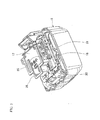
- an impact driver 1 includes a main body housing 2 and a battery pack 3.
- the main body housing 2 has a body portion 4, a rear cover 5, a handle portion 6, and a battery holding portion 7.
- the body portion 4 is formed in a substantially cylindrical shape, and extends in the longitudinal direction of the impact driver 1 (the lateral direction in FIGS. 1 and 2 ).
- a motor 8 is accommodated in the body portion 4.
- the rear cover 5 has a tubular shape that opens on a body portion 4 side of the rear cover 5, and is attached to a rear end of the body portion 4.
- the impact driver 1 is an example of the electric power tool of the present invention
- the main body housing 2 is an example of the housing of the present invention.
- a hammer case 9 is mounted on the front (rightward in FIGS. 1 and 2 ) of the body portion 4.
- An impact mechanism and an anvil (not shown) disposed to protrude from a distal end face of the hummer case 9 are accommodated in the hammer case 9.
- the anvil is axially supported so as to rotate in the hammer case 9, and a socket holding portion 10 on which a tool and a socket can be mounted is provided at a distal end of the anvil.
- the impact mechanism converts rotation of the motor 8 to a rotational impact force, and transmits the rotational impact force to the tool and the socket.
- the handle portion 6 is connected to the body portion 4 so as to extend downward from the body portion 4.
- a switch 12 having a trigger 11 is accommodated in the handle portion 6.
- the battery holding portion 7 is formed at a lower end of the handle portion 6.
- Guide rails (not shown) extending in the longitudinal direction are formed at left and right lower ends of the battery holding portion 7.
- a pair of left and right slide rails 15, 15 are provided on the battery pack 3 described below, and the guide rails hold the pair of left and right slide rails 15, 15 therebetween from outside when the battery pack 3 is mounted on the battery holding portion 7.
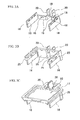
- a terminal base 17 (see FIGS. 2 and 3C ) having terminal plates 16, 16 protruding downward therefrom is placed between the slide rails 15, 15 in the battery holding portion 7.
- each terminal plate 16 has a rectangular shape having a short side in the vertical direction and a longer side in the longitudinal direction, and the terminal plates 16, 16 are placed parallel to each other so as to be separated from each other and to face each other in the lateral direction.
- a plurality of through holes 18 arranged in the longitudinal direction is formed in an upper part of each terminal plate 16.
- Positive and negative electrodes 20, which extend in the vertical direction and face each other, are connected to rear ends of the terminal plates 16, 16 via arm members 19 extending in the lateral direction.
- a through hole 18 is also formed in a central portion of each arm member 19 and a lower end of each electrode 20.
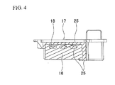
- a buffer member 25 is integrally formed on an upper portion (an upper end and an upper surface portion) of each terminal plate 16 by double molding.
- the buffer member 25 is made of an elastomer having heat resistance and elasticity.
- the elastomer is poured in a mold of the buffer member 25 so as to be integrally formed with the upper portion of each terminal plate 16 in a state of the through holes 18 in the terminal plate 16 being filled with the elastomer as shown in FIG. 4 .
- FIG. 4 As shown in FIG.
- the buffer member 25 is also integrally formed on a surface of each arm member 19 with the through hole 18 in the arm member 19 being filled with the elastomer, and the buffer member 25 is also integrally formed on a lower portion (a lower end and a lower surface portion) of each electrode 20 in a state of the through hole 18 in the electrode 20 being filled with the elastomer.
- the buffer member 25 of the arm member 19 and the buffer member 25 of the electrode 20 are formed continuously and integrally with the buffer member 25 of the terminal plate 16.
- the elastomer is an example of the buffer material of the present invention.
- the terminal plates 16, 16 and the arm members 19, 19, which have the buffer member 25 integrally formed thereon by double molding as shown in FIG. 3B are attached to the terminal base 17 made of a resin.
- the terminal plates 16, 16 and the arm members 19, 19 are attached to a lower surface of the terminal base 17 with the buffer members 25 interposed therebetween.
- the electrodes 20, 20 are accommodated in an electrode accommodating space 26 that opens in an upper surface of the terminal base 17.
- the switch 12 (see FIG. 1 ) is connected to each electrode 20 via a lead wire (not shown).
- the slide rails 15, 15 (see FIGS. 1 and 2 ) extending in the longitudinal direction are formed at left and right ends of the battery pack 3.
- Charging/discharging terminals 31, 31 (see FIG. 5 ) are placed between the slide rails 15, 15 in the battery pack 3 at the same interval as that between the terminal plates 16, 16.
- slits 32, 32 extending in the longitudinal direction are formed in an upper surface of the battery pack 3 at the same interval as that between the charging/discharging terminals 31, 31.
- Each of the charging/discharging terminals 31 faces the inside of a corresponding one of the slits 32.
- the slide rails 15, 15 of the battery pack 3 shown in FIG. 2 are slid along the left and right guide rails of the battery holding portion 7. Accordingly, the guide rails hold the slide rails 15 therebetween, so that the battery pack 3 is mounted on the battery holding portion 7.
- the terminal plates 16, 16 enter the slits 32, 32, and thus are slid and inserted into the charging/discharging terminals 31, 31. Accordingly, the terminal plates 16, 16 are electrically connected to the charging/discharging terminals 31, 31.
- the switch 12 is turned on, thereby the battery pack 3 supplies electric power to the motor 3.
- vibrations are produced by the impact during operation of the impact driver 1.
- Such vibrations are continuously transmitted from the main body housing 2 to the terminal plates 16, 16 through the terminal base 17. If the terminal plates 16, 16 are thus continuously vibrated, the terminal plates 16, 16 rub against the charging/discharging terminals 31, 31, thereby causing melting of the terminal plates 16, 16.
- the-vibrations are absorbed by the buffer members 25 interposed between the terminal base 17 and the terminal plates 16, 16 and between the terminal base 17 and the arm members 19, 19, so that vibrations are less likely to be transmitted to the terminal plates 16, 16.
- the buffer members 25 described above needs only to be formed on the terminal base 17, and no additional processing is required for the charging/discharging terminals 31. This can simplify the structure of the charging/discharging terminals 31.
- the buffer members 25 made of the elastomer can suppress transmission of the vibrations from the terminal base 17 to the terminal plates 16, 16. This can suppress rubbing of the terminal plates 16, 16 against the charging/discharging terminals 31, 31 of the battery pack 3, and thus can suppress melting of the terminal plates 16, 16. Moreover, it can be realized to suppress melting of the terminal plate only by the buffer member 25 interposed at least between the terminal base 17 and the terminal plates 16, 16, and between the terminal base 17 and the arm members 19, 19. Therefore, the structure that suppresses melting of the terminal plates 16, 16 can be inexpensively and easily implemented.
- the buffer members 25 made of the elastomer is held between the terminal base 17 and the terminal plates 16, 16 with the through holes 18 in the terminal plates 16, 16 being filled with the elastomer. This can increase the strength in integrating each terminal plate 16 with the buffer member 25. Moreover, the buffer members 25 are held between the terminal base 17 and the arm members 19, 19 with the through holes 18 in the arm members 19, 19 being filled with the elastomer. This can increase the strength in integrating each arm member 19 with the buffer member 25.
- the present invention is not limited to the above embodiment, and the configuration can be partially changed as appropriate without departing from the spirit and scope of the invention.
- the above embodiment is described with respect to an example in which the buffer members 25 are made of the elastomer.
- the buffer members may be made of a fluorine-containing rubber having high heat resistance.
- the above embodiment is described with respect to an example in which the terminal plates 16, 16 and the arm members 19, 19 are attached to the lower surface of the terminal base 17 with the buffer members 25 interposed between the lower surface of the terminal base 17 and the terminal plates 16, 16 and between the lower surface of the terminal base 17 and the arm members 19, 19.
- the terminal plates 16, 16 may be attached to the lower surface of the terminal base 17 with the buffer members 25 interposed therebetween, and no buffer member 25 may be provided between the lower surface of the terminal base 17 and the arm members 19, 19.
- the above embodiment is described with respect to an example in which the present invention is applied to an impact driver.
- the present invention is not limited to this, and the present invention may be applied to an electric power tool such as a rechargeable drill driver in which a terminal plate is slid and mounted on a battery pack.
Landscapes
- Engineering & Computer Science (AREA)
- Mechanical Engineering (AREA)
- Battery Mounting, Suspending (AREA)
- Connection Of Batteries Or Terminals (AREA)
- Portable Power Tools In General (AREA)
Applications Claiming Priority (1)
| Application Number | Priority Date | Filing Date | Title |
|---|---|---|---|
| JP2011270368A JP2013121628A (ja) | 2011-12-09 | 2011-12-09 | 電動工具 |
Publications (1)
| Publication Number | Publication Date |
|---|---|
| EP2602065A2 true EP2602065A2 (en) | 2013-06-12 |
Family
ID=47146200
Family Applications (1)
| Application Number | Title | Priority Date | Filing Date |
|---|---|---|---|
| EP12190589.7A Withdrawn EP2602065A2 (en) | 2011-12-09 | 2012-10-30 | Electric power tool |
Country Status (4)
| Country | Link |
|---|---|
| US (1) | US20130149581A1 (enExample) |
| EP (1) | EP2602065A2 (enExample) |
| JP (1) | JP2013121628A (enExample) |
| CN (1) | CN103158118A (enExample) |
Cited By (3)
| Publication number | Priority date | Publication date | Assignee | Title |
|---|---|---|---|---|
| WO2017108433A1 (de) * | 2015-12-22 | 2017-06-29 | Robert Bosch Gmbh | Handwerkzeugmaschine |
| CN109564827A (zh) * | 2016-09-27 | 2019-04-02 | 欧姆龙株式会社 | 触发开关 |
| EP4454825A1 (en) * | 2023-04-27 | 2024-10-30 | Black & Decker, Inc. | Power module including an integrated battery interface for power tool |
Families Citing this family (5)
| Publication number | Priority date | Publication date | Assignee | Title |
|---|---|---|---|---|
| JP6085225B2 (ja) | 2013-06-27 | 2017-02-22 | 株式会社マキタ | ネジ締め電動工具 |
| JP6364646B2 (ja) * | 2013-11-29 | 2018-08-01 | 工機ホールディングス株式会社 | 電動工具 |
| JP7516076B2 (ja) * | 2020-03-10 | 2024-07-16 | 株式会社マキタ | 電動工具 |
| CN116472142A (zh) | 2020-10-28 | 2023-07-21 | 罗伯特·博世有限公司 | 动力工具 |
| EP4342639A1 (de) * | 2022-09-23 | 2024-03-27 | C. & E. Fein GmbH | Lagervorrichtung für ein akkumulatormodul an einem handwerkzeug |
Family Cites Families (14)
| Publication number | Priority date | Publication date | Assignee | Title |
|---|---|---|---|---|
| JPH06113705A (ja) * | 1992-09-30 | 1994-04-26 | Shuichiro Tashiro | 蹄鉄及びその製造法 |
| US5553675A (en) * | 1994-06-10 | 1996-09-10 | Minnesota Mining And Manufacturing Company | Orthopedic surgical device |
| JP3166119B2 (ja) * | 1996-02-16 | 2001-05-14 | 矢崎総業株式会社 | 基板用可動コネクタ及びコネクタ端子 |
| JPH10296660A (ja) * | 1997-04-25 | 1998-11-10 | Hitachi Koki Co Ltd | 電池式携帯用工具 |
| JP2001325932A (ja) * | 2000-05-16 | 2001-11-22 | Makita Corp | 充電式電動工具 |
| JP4269567B2 (ja) * | 2002-04-05 | 2009-05-27 | 日立工機株式会社 | 電池工具 |
| JP2004147360A (ja) * | 2002-10-21 | 2004-05-20 | Makita Corp | 充電器 |
| DE102005052428B4 (de) * | 2005-11-03 | 2015-06-18 | Robert Bosch Gmbh | Elektrowerkzeugmaschine |
| JP4981392B2 (ja) * | 2006-09-20 | 2012-07-18 | 日立工機株式会社 | アダプタ、アダプタと電池パックの組み合わせ、及びそれらを備えた電動工具 |
| JP4977533B2 (ja) * | 2007-06-07 | 2012-07-18 | 株式会社マキタ | 可搬型電動工具 |
| JP2010030024A (ja) * | 2008-07-31 | 2010-02-12 | Makita Corp | 電気機器 |
| CN101502980B (zh) * | 2008-09-18 | 2010-08-11 | 虞新华 | 采用浇灌形成销钉式连接的复合保温砌块的生产方法 |
| JP5436850B2 (ja) * | 2008-12-19 | 2014-03-05 | 株式会社マキタ | 電動工具のバッテリパック |
| US8268478B2 (en) * | 2009-08-17 | 2012-09-18 | Sb Limotive Co., Ltd. | Rechargeable battery having anti-vibration member |
-
2011
- 2011-12-09 JP JP2011270368A patent/JP2013121628A/ja active Pending
-
2012
- 2012-10-12 CN CN2012103857898A patent/CN103158118A/zh active Pending
- 2012-10-30 EP EP12190589.7A patent/EP2602065A2/en not_active Withdrawn
- 2012-10-31 US US13/665,378 patent/US20130149581A1/en not_active Abandoned
Non-Patent Citations (1)
| Title |
|---|
| "General Catalog", October 2011, MAKITA CORPORATION, pages: 16 |
Cited By (5)
| Publication number | Priority date | Publication date | Assignee | Title |
|---|---|---|---|---|
| WO2017108433A1 (de) * | 2015-12-22 | 2017-06-29 | Robert Bosch Gmbh | Handwerkzeugmaschine |
| US11420315B2 (en) | 2015-12-22 | 2022-08-23 | Robert Bosch Gmbh | Handheld machine tool |
| CN109564827A (zh) * | 2016-09-27 | 2019-04-02 | 欧姆龙株式会社 | 触发开关 |
| US10699854B2 (en) | 2016-09-27 | 2020-06-30 | Omron Corporation | Trigger switch |
| EP4454825A1 (en) * | 2023-04-27 | 2024-10-30 | Black & Decker, Inc. | Power module including an integrated battery interface for power tool |
Also Published As
| Publication number | Publication date |
|---|---|
| CN103158118A (zh) | 2013-06-19 |
| JP2013121628A (ja) | 2013-06-20 |
| US20130149581A1 (en) | 2013-06-13 |
Similar Documents
| Publication | Publication Date | Title |
|---|---|---|
| EP2602065A2 (en) | Electric power tool | |
| US11845153B2 (en) | Power tool including a battery pack isolation system | |
| CN105406012B (zh) | 用于手持式工具机的蓄电池组 | |
| EP2625006B1 (en) | Battery retention system for a power tool | |
| US10562167B2 (en) | Striking tool | |
| CN107567663B (zh) | 用于手持式工具机的蓄电池组和手持式工具机 | |
| US9293747B2 (en) | Multi cell carriers | |
| EP2090406A1 (en) | Electric tools | |
| US10511008B2 (en) | Battery contact with a surface texture | |
| CN107408649A (zh) | 用于手持式工具机的蓄电池组和用于制造用于手持式工具机的蓄电池组的方法 | |
| CN107431158A (zh) | 用于手持式工具机的蓄电池组 | |
| US20220384894A1 (en) | Battery pack and electrical instrument | |
| US20100263896A1 (en) | Hand-held power tool having a two-part housing | |
| WO2014119126A1 (ja) | 手持式電動切削機 | |
| WO2021065268A1 (ja) | 電動工具、及び電池パック | |
| US20070277992A1 (en) | Percussion hand-held power tool with axially displaceable percussion mechanism | |
| JP4399409B2 (ja) | バッテリ式電動工具 | |
| JP7262057B2 (ja) | 電動工具、及び電池パック | |
| CN113302025B (zh) | 手持式工具机 | |
| JP7266214B2 (ja) | 電動工具、及び電池パック | |
| WO2021153041A1 (ja) | 電池パック、及び電動工具 | |
| JP6780782B2 (ja) | 電気機器 | |
| CN114335863B (zh) | 电池包 | |
| JP2019102217A (ja) | 電池パック及びそれを備えた電気機器 | |
| CN118234600A (zh) | 用于可充电电池的子壳体中的弹簧接触部 |
Legal Events
| Date | Code | Title | Description |
|---|---|---|---|
| PUAI | Public reference made under article 153(3) epc to a published international application that has entered the european phase |
Free format text: ORIGINAL CODE: 0009012 |
|
| AK | Designated contracting states |
Kind code of ref document: A2 Designated state(s): AL AT BE BG CH CY CZ DE DK EE ES FI FR GB GR HR HU IE IS IT LI LT LU LV MC MK MT NL NO PL PT RO RS SE SI SK SM TR |
|
| AX | Request for extension of the european patent |
Extension state: BA ME |
|
| STAA | Information on the status of an ep patent application or granted ep patent |
Free format text: STATUS: THE APPLICATION HAS BEEN WITHDRAWN |
|
| 18W | Application withdrawn |
Effective date: 20150421 |