EP2601702B1 - Hybridmembrane mit fluordotiertem titandioxid - Google Patents
Hybridmembrane mit fluordotiertem titandioxid Download PDFInfo
- Publication number
- EP2601702B1 EP2601702B1 EP11761701.9A EP11761701A EP2601702B1 EP 2601702 B1 EP2601702 B1 EP 2601702B1 EP 11761701 A EP11761701 A EP 11761701A EP 2601702 B1 EP2601702 B1 EP 2601702B1
- Authority
- EP
- European Patent Office
- Prior art keywords
- fluorine
- membrane
- particles
- inorganic
- membranes
- Prior art date
- Legal status (The legal status is an assumption and is not a legal conclusion. Google has not performed a legal analysis and makes no representation as to the accuracy of the status listed.)
- Active
Links
Images






Classifications
-
- H—ELECTRICITY
- H01—ELECTRIC ELEMENTS
- H01M—PROCESSES OR MEANS, e.g. BATTERIES, FOR THE DIRECT CONVERSION OF CHEMICAL ENERGY INTO ELECTRICAL ENERGY
- H01M8/00—Fuel cells; Manufacture thereof
- H01M8/10—Fuel cells with solid electrolytes
-
- H—ELECTRICITY
- H01—ELECTRIC ELEMENTS
- H01M—PROCESSES OR MEANS, e.g. BATTERIES, FOR THE DIRECT CONVERSION OF CHEMICAL ENERGY INTO ELECTRICAL ENERGY
- H01M8/00—Fuel cells; Manufacture thereof
- H01M8/10—Fuel cells with solid electrolytes
- H01M8/1016—Fuel cells with solid electrolytes characterised by the electrolyte material
-
- B—PERFORMING OPERATIONS; TRANSPORTING
- B01—PHYSICAL OR CHEMICAL PROCESSES OR APPARATUS IN GENERAL
- B01D—SEPARATION
- B01D67/00—Processes specially adapted for manufacturing semi-permeable membranes for separation processes or apparatus
- B01D67/0039—Inorganic membrane manufacture
- B01D67/0044—Inorganic membrane manufacture by chemical reaction
-
- B—PERFORMING OPERATIONS; TRANSPORTING
- B01—PHYSICAL OR CHEMICAL PROCESSES OR APPARATUS IN GENERAL
- B01D—SEPARATION
- B01D67/00—Processes specially adapted for manufacturing semi-permeable membranes for separation processes or apparatus
- B01D67/0039—Inorganic membrane manufacture
- B01D67/0076—Pretreatment of inorganic membrane material prior to membrane formation, e.g. coating of metal powder
-
- B—PERFORMING OPERATIONS; TRANSPORTING
- B01—PHYSICAL OR CHEMICAL PROCESSES OR APPARATUS IN GENERAL
- B01D—SEPARATION
- B01D67/00—Processes specially adapted for manufacturing semi-permeable membranes for separation processes or apparatus
- B01D67/0079—Manufacture of membranes comprising organic and inorganic components
-
- B—PERFORMING OPERATIONS; TRANSPORTING
- B01—PHYSICAL OR CHEMICAL PROCESSES OR APPARATUS IN GENERAL
- B01D—SEPARATION
- B01D69/00—Semi-permeable membranes for separation processes or apparatus characterised by their form, structure or properties; Manufacturing processes specially adapted therefor
- B01D69/14—Dynamic membranes
- B01D69/141—Heterogeneous membranes, e.g. containing dispersed material; Mixed matrix membranes
- B01D69/148—Organic/inorganic mixed matrix membranes
-
- B—PERFORMING OPERATIONS; TRANSPORTING
- B01—PHYSICAL OR CHEMICAL PROCESSES OR APPARATUS IN GENERAL
- B01D—SEPARATION
- B01D71/00—Semi-permeable membranes for separation processes or apparatus characterised by the material; Manufacturing processes specially adapted therefor
- B01D71/02—Inorganic material
-
- B—PERFORMING OPERATIONS; TRANSPORTING
- B01—PHYSICAL OR CHEMICAL PROCESSES OR APPARATUS IN GENERAL
- B01D—SEPARATION
- B01D71/00—Semi-permeable membranes for separation processes or apparatus characterised by the material; Manufacturing processes specially adapted therefor
- B01D71/02—Inorganic material
- B01D71/024—Oxides
-
- C—CHEMISTRY; METALLURGY
- C25—ELECTROLYTIC OR ELECTROPHORETIC PROCESSES; APPARATUS THEREFOR
- C25B—ELECTROLYTIC OR ELECTROPHORETIC PROCESSES FOR THE PRODUCTION OF COMPOUNDS OR NON-METALS; APPARATUS THEREFOR
- C25B13/00—Diaphragms; Spacing elements
- C25B13/04—Diaphragms; Spacing elements characterised by the material
-
- C—CHEMISTRY; METALLURGY
- C25—ELECTROLYTIC OR ELECTROPHORETIC PROCESSES; APPARATUS THEREFOR
- C25B—ELECTROLYTIC OR ELECTROPHORETIC PROCESSES FOR THE PRODUCTION OF COMPOUNDS OR NON-METALS; APPARATUS THEREFOR
- C25B13/00—Diaphragms; Spacing elements
- C25B13/04—Diaphragms; Spacing elements characterised by the material
- C25B13/05—Diaphragms; Spacing elements characterised by the material based on inorganic materials
-
- C—CHEMISTRY; METALLURGY
- C25—ELECTROLYTIC OR ELECTROPHORETIC PROCESSES; APPARATUS THEREFOR
- C25B—ELECTROLYTIC OR ELECTROPHORETIC PROCESSES FOR THE PRODUCTION OF COMPOUNDS OR NON-METALS; APPARATUS THEREFOR
- C25B13/00—Diaphragms; Spacing elements
- C25B13/04—Diaphragms; Spacing elements characterised by the material
- C25B13/08—Diaphragms; Spacing elements characterised by the material based on organic materials
-
- C—CHEMISTRY; METALLURGY
- C25—ELECTROLYTIC OR ELECTROPHORETIC PROCESSES; APPARATUS THEREFOR
- C25B—ELECTROLYTIC OR ELECTROPHORETIC PROCESSES FOR THE PRODUCTION OF COMPOUNDS OR NON-METALS; APPARATUS THEREFOR
- C25B9/00—Cells or assemblies of cells; Constructional parts of cells; Assemblies of constructional parts, e.g. electrode-diaphragm assemblies; Process-related cell features
- C25B9/17—Cells comprising dimensionally-stable non-movable electrodes; Assemblies of constructional parts thereof
- C25B9/19—Cells comprising dimensionally-stable non-movable electrodes; Assemblies of constructional parts thereof with diaphragms
-
- H—ELECTRICITY
- H01—ELECTRIC ELEMENTS
- H01M—PROCESSES OR MEANS, e.g. BATTERIES, FOR THE DIRECT CONVERSION OF CHEMICAL ENERGY INTO ELECTRICAL ENERGY
- H01M8/00—Fuel cells; Manufacture thereof
- H01M8/10—Fuel cells with solid electrolytes
- H01M8/1016—Fuel cells with solid electrolytes characterised by the electrolyte material
- H01M8/1018—Polymeric electrolyte materials
- H01M8/1041—Polymer electrolyte composites, mixtures or blends
- H01M8/1046—Mixtures of at least one polymer and at least one additive
- H01M8/1048—Ion-conducting additives, e.g. ion-conducting particles, heteropolyacids, metal phosphate or polybenzimidazole with phosphoric acid
-
- B—PERFORMING OPERATIONS; TRANSPORTING
- B01—PHYSICAL OR CHEMICAL PROCESSES OR APPARATUS IN GENERAL
- B01D—SEPARATION
- B01D2323/00—Details relating to membrane preparation
- B01D2323/08—Specific temperatures applied
- B01D2323/081—Heating
-
- B—PERFORMING OPERATIONS; TRANSPORTING
- B01—PHYSICAL OR CHEMICAL PROCESSES OR APPARATUS IN GENERAL
- B01D—SEPARATION
- B01D2323/00—Details relating to membrane preparation
- B01D2323/26—Spraying processes
-
- B—PERFORMING OPERATIONS; TRANSPORTING
- B01—PHYSICAL OR CHEMICAL PROCESSES OR APPARATUS IN GENERAL
- B01D—SEPARATION
- B01D2323/00—Details relating to membrane preparation
- B01D2323/48—Influencing the pH
-
- B—PERFORMING OPERATIONS; TRANSPORTING
- B01—PHYSICAL OR CHEMICAL PROCESSES OR APPARATUS IN GENERAL
- B01D—SEPARATION
- B01D2325/00—Details relating to properties of membranes
- B01D2325/26—Electrical properties
-
- B—PERFORMING OPERATIONS; TRANSPORTING
- B01—PHYSICAL OR CHEMICAL PROCESSES OR APPARATUS IN GENERAL
- B01D—SEPARATION
- B01D2325/00—Details relating to properties of membranes
- B01D2325/42—Ion-exchange membranes
-
- H—ELECTRICITY
- H01—ELECTRIC ELEMENTS
- H01M—PROCESSES OR MEANS, e.g. BATTERIES, FOR THE DIRECT CONVERSION OF CHEMICAL ENERGY INTO ELECTRICAL ENERGY
- H01M2300/00—Electrolytes
- H01M2300/0017—Non-aqueous electrolytes
- H01M2300/0065—Solid electrolytes
- H01M2300/0068—Solid electrolytes inorganic
- H01M2300/0071—Oxides
-
- H—ELECTRICITY
- H01—ELECTRIC ELEMENTS
- H01M—PROCESSES OR MEANS, e.g. BATTERIES, FOR THE DIRECT CONVERSION OF CHEMICAL ENERGY INTO ELECTRICAL ENERGY
- H01M2300/00—Electrolytes
- H01M2300/0017—Non-aqueous electrolytes
- H01M2300/0065—Solid electrolytes
- H01M2300/0082—Organic polymers
-
- H—ELECTRICITY
- H01—ELECTRIC ELEMENTS
- H01M—PROCESSES OR MEANS, e.g. BATTERIES, FOR THE DIRECT CONVERSION OF CHEMICAL ENERGY INTO ELECTRICAL ENERGY
- H01M2300/00—Electrolytes
- H01M2300/0088—Composites
- H01M2300/0091—Composites in the form of mixtures
-
- Y—GENERAL TAGGING OF NEW TECHNOLOGICAL DEVELOPMENTS; GENERAL TAGGING OF CROSS-SECTIONAL TECHNOLOGIES SPANNING OVER SEVERAL SECTIONS OF THE IPC; TECHNICAL SUBJECTS COVERED BY FORMER USPC CROSS-REFERENCE ART COLLECTIONS [XRACs] AND DIGESTS
- Y02—TECHNOLOGIES OR APPLICATIONS FOR MITIGATION OR ADAPTATION AGAINST CLIMATE CHANGE
- Y02E—REDUCTION OF GREENHOUSE GAS [GHG] EMISSIONS, RELATED TO ENERGY GENERATION, TRANSMISSION OR DISTRIBUTION
- Y02E60/00—Enabling technologies; Technologies with a potential or indirect contribution to GHG emissions mitigation
- Y02E60/30—Hydrogen technology
- Y02E60/50—Fuel cells
-
- Y—GENERAL TAGGING OF NEW TECHNOLOGICAL DEVELOPMENTS; GENERAL TAGGING OF CROSS-SECTIONAL TECHNOLOGIES SPANNING OVER SEVERAL SECTIONS OF THE IPC; TECHNICAL SUBJECTS COVERED BY FORMER USPC CROSS-REFERENCE ART COLLECTIONS [XRACs] AND DIGESTS
- Y02—TECHNOLOGIES OR APPLICATIONS FOR MITIGATION OR ADAPTATION AGAINST CLIMATE CHANGE
- Y02P—CLIMATE CHANGE MITIGATION TECHNOLOGIES IN THE PRODUCTION OR PROCESSING OF GOODS
- Y02P70/00—Climate change mitigation technologies in the production process for final industrial or consumer products
- Y02P70/50—Manufacturing or production processes characterised by the final manufactured product
Definitions
- the invention comprises producing inorganic/organic hybrid membranes based on a material capable of conducting ions, and in particular protons, in which nanometric particles of TiO 2 doped with fluorine (TiO 2 F) are dispersed as a filler.
- the resulting membranes are characterised by better proton conductivity and better mechanical properties than similar systems which do not include the fillers. Furthermore the proton conductivity and the performance of some of the resulting inorganic/organic hybrid membranes in PEMFC fuel cells are less compromised by dehydration than similar systems which do not include the fillers.
- the invention relates to the use of a family of nanometric inorganic fillers based on TiO 2 doped with fluorine-based species in the preparation of inorganic/organic hybrid ion exchange membranes and in particular proton exchange membranes for use in fuel cells and PEM electrolysers.
- a fuel cell is a device which converts the chemical energy of the reagents fed to it directly into electrical energy.
- Fuel cells are well known in the art and are for example described in Cappadonia et al., Ulmann's Encyclopedia of Industrial Chemistry, Fuel Cells, 2005, 1-23, Wiley-VCH .
- a fuel cell is an electrochemical device and not a heat engine, it can easily achieve very high efficiencies, even more than twice those characteristic of conventional combustion engines.
- fuel cells There are many different families of fuel cells distinguished by the materials from which they are made and the temperature at which they operate in optimum mode.
- One of the most intensively studied families is the one including polymer electrolyte fuel cells (Proton Exchange Membrane Fuel Cells, PEMFC).
- PEMFC operate at low temperature (T ⁇ 130°C) and comprise a polymer membrane capable of conducting protons (Proton Exchange Membrane, PEM) separating two porous electrodes through which reagents and reaction products can diffuse (Gas Diffusion Layers, GDL).
- PEMFC electrocatalyst material used to promote the electrochemical reactions involved in the functioning of the device.
- PEMFC are silent devices with no moving parts, of simple construction, that are capable of achieving high efficiencies (even over 55%) and are characterised by high energy and power densities. Also, PEMFC do not produce fine powders or pollutants such as sulphur or nitrogen oxides (SO x and NO x ) and, if fed with pure hydrogen, the only product of their operation is water. All these characteristics make PEMFC particularly suitable devices for providing power for vehicles or portable electronic devices such as multimedia readers, portable computers and other devices, without causing any harm to the environment.
- SO x and NO x sulphur or nitrogen oxides
- the core of every PEMFC is the proton conducting membrane, through which protons obtained at the anode following oxidation of the fuel can be transported to the cathode where they are recombined with the products of the reduction reaction of the oxidising agent.
- the latter generally comprises oxygen present in the air.
- the most widely used materials in manufacturing proton exchange membranes are perfluorinated copolymers such as NafionTM, HyflonIon, Dow polymer and others. All these materials comprise a main perfluorinated polymer chain, similar to that of TeflonTM, from which there extend perfluoroether side chains terminating in an -SO 3 H group characterised by high acidity.
- the materials are capable of conducting protons in that, as soon as water is present, there is a marked phase separation into domains of different polarity.
- the domains having the highest polarity include water, which is made strongly acid by the - SO 3 H groups delimiting the domains.
- These high polarity domains are immersed in a low polarity matrix comprising the main perfluorinated chains and the perfluoroether side chains. Proton conduction occurs when different polar domains come into contact following fluctuations in the low polarity matrix. When this happens, there is long range migration of protons from one high polarity domain to another in the form of H 3 O + ions.
- the perfluorinated copolymers described above characteristically have high proton conductivity and excellent chemical stability.
- perfluorinated copolymers do not always succeed in preventing the reagents from permeating from one electrode to the other .
- the microscopic dynamics of the low and high polarity domains present in the perfluorinated copolymers are intimately associated.
- the maximum temperature at which a perfluorinated copolymer can operate efficiently is approximately 80-90°C; above this there are transitions which change the microscopic structure of the material, causing it to dehydrate easily with a consequent fall in proton conductivity.
- inorganic/organic hybrid membranes comprise a material capable of conducting protons, such as for example National, in which nanometric inorganic powders, such as oxides and phosphonates acting as fillers which may have been given surface functionality, are dispersed.
- the resulting inorganic/organic hybrid materials may be characterised by better mechanical properties than the proton-conducting starting materials; the proton conductivity may be better and be less influenced by the level of hydration under which they operate.
- Proton-conducting inorganic/organic hybrid membranes are well known in the art and are described for example in the following articles: Di Noto et al., Journal of Power Sources, 178 (2008) 561-574 ; Di Noto et al., Journal of Power Source, 187 (2009) 57-66 ; Chen et al., Journal of Membrane Science, 307 (2008) 10-20 .
- Fuel cells containing ion-exchange membranes are also described in US7713899 , US7661542 and US2008/0248356 .
- Another family of devices of great technological interest based on functional elements quite similar to those described above for applications in PEMFC is that of PEM electrolysers (Proton Exchange Membrane electrolysers).
- a PEM electrolyser is essentially a PEM fuel cell which acts in reverse by converting the electrical power and the water fed to it into hydrogen and oxygen having a high degree of purity (in excess of 99.9%) through an electrolysis process.
- PEM electrolysers are used to produce pure gases only when they are needed for a particular application, thus avoiding the need to store them in heavy bulky cylinders subject to strict safety standards for high-pressure highly flammable gases.
- the core of a PEM electrolyser comprises the same proton exchange membrane as is used in a PEMFC; the material used to make the membrane must have optimum proton conductivity and high chemical and electrochemical stability.
- PEM electrolysers are well known in the art and arc for example described in Spiegel, Designing & Building Fuel Cells, 2007, 346-348, MeGraw-Hill and in Grot, Fluorinated Ionomers, 2008, 113-116, William andrew Inc.
- WO2005/090235 and WO2006/077203 describe the production of undoped titanium dioxide.
- Fluorine-doped titanium dioxide is described in: Li et al., Journal of Fluorine Chemistry, Elsevier, vol. 126. n. I. 69-77, 2005 ; Todorova et al. Material Science and Engineering, Elsevier, vol. 1.52, n. 1-3, 50-54, 2008 ; Czoska et al. Journal of Physical Chemistry, vol. 112. 8951 - 8956, 2008 ; US5597515 ; WO 2009/113045 .
- an inorganic/organic hybrid membrane containing fluorine-doped TiO 2 has better ion conductivity and mechanical properties than the inorganic/organic hybrid membranes known in the art.
- the membranes to which this invention relates will conduct protons but can also conduct other ions that are not protons (for example NR 4 + where R is a C 1 -C 6 alkyl radical such as methyl or ethyl).
- the present invention therefore relates to the use of fluorine-doped TiO 2 in the preparation of proton-exchange inorganic/organic hybrid membranes, proton-exchange inorganic/organic hybrid membranes thus obtained and the fuel cells and PEM electrolysers containing them.
- fluorine-doped TiO 2 preferably means particles of said crystalline metal oxide having an average particle size of less than 500 nm, preferably between 10 and 500 nm, containing fluorine, hydroxy groups, ammonium cations and nitrogen oxides.
- fluorine-doped TiO 2 particles, fluorine-doped titanium dioxide particles or FT mean particles of anatase having an average particle size of less than 500 nm, preferably between 10 and 500 nm, even more preferably between 50 and 300 nm, which have fluorine, hydroxy groups, ammonium cations and nitrogen oxides on their surface.
- More particularly said particles are of the "shell-core” type, that is they are formed of an internal core essentially comprising crystalline titanium dioxide, preferably anatase, and a surface coating having a mean thickness of between 0.3 and 20 nm, preferably between 0.6 and 10 nm.
- the surface coating contains fluorine atoms bridging with titanium atoms and terminal fluorine atoms; it is also rich in hydroxy groups, ammonium cations and nitrogen oxides located on the surface of the coating.
- the process for the production of fluorine-doped TiO 2 comprises the following stages:
- This process includes the extraction of titanium from the ilmenite ore (FeTiO 3 ), which may possibly be enriched; this extraction takes place within a suitable reactor, causing the ore to react with a concentrated aqueous solution of between 10% and 37% by weight and preferably approximately 30% by weight of NH 4 HF 2 having a pH preferably between 5.5 and 5.7.
- a concentrated aqueous solution of between 10% and 37% by weight and preferably approximately 30% by weight of NH 4 HF 2 having a pH preferably between 5.5 and 5.7.
- Chemical analysis of the ilmenite performed using ICP-AES before the start of the reaction with NH 4 HF 2 has shown that ore contains traces ( ⁇ 1% by weight) of Al, Ca, Co, Ni and Zn. 1.1% by weight of W is also present.
- the ore is added to the reactor preferably with an average particle size of 0.05-1.5 mm, even more preferably approximately 0.2 mm, and may be preheated to 80-120°C, preferably to approximately 100°C. It suggested that the ore should be added to the base of the reactor by means of a system which prevents the gases present within the reactor from rising up the inlet pipe for said sand.
- the aqueous solution of NH 4 HF 2 is preferably preheated to 50-100°C, preferably approximately 80°C; the ratio by weight between the ilmenite and the NH 4 HF 2 solution (preferably 30% by weight) is normally between 1:6 and 1:8, and is preferably approximately 1:7.5.
- the reactor has equipment to stir the ilmenite sand in such a way as to encourage intimate contact between the reagents (ilmenite and solution), in particular at the bottom of the reactor.
- the stirring is possibly such as not to create turbulent motion in the top of the reactor; in the best embodiment the stirring speed should not exceed 20 rpm, preferably 10 rpm.
- the temperature within the reactor is kept at 100-110°C, preferably 104-106°C, and even more preferably approximately 105°C, at a pressure of between approximately 1 and 2 bar; this may be achieved using the conventional means known in the art, for example a heating jacket system on the outside of the reactor; in the best embodiment the greatest quantity of heat is transmitted through the bottom of the reactor, where the concentration of reagents is highest; also, in order to prevent the escape of gaseous compounds into the outside environment, it is recommended that a leaktight reactor should be used.
- the reaction has a preferred duration of 40 to 80 minutes.
- the pH within the reactor under these operating conditions is approximately 6.5-7.0.
- Gaseous ammonia is produced by the reaction; this can be conveyed outside the reactor and absorbed in water to obtain a concentrated solution (approximately 24% by weight) of ammonium hydroxide NH 4 OH, which can in turn be used during the subsequent stages of hydrolysis of the titanium salts. Removal of the ammonia also makes it possible to control the pressure within the reactor (normally approximately 1 bar).
- the reaction between FeTiO 3 and NH 4 HF 2 (in aqueous solution) produces two salts: ammonium hexafluorotitanate (NH 4 ) 2 TiF 6 and ammonium (ferric) hexachloroferrate (NH 4 ) 3 FeF 6 .
- the titanium salt has a solubility which depends directly on temperature and is inversely dependent on the concentration of NH 4 HF 2 ; it therefore remains in solution under the reaction conditions.
- the iron salt instead has negligible solubility and remains in the form of a solid dispersion.
- An aqueous solution of NH 4 HF 2 and (NH 4 ) 2 TiF 6 containing the dispersed (NH 4 ) 3 FeF 6 salt is recovered from the reactor.
- the dispersion leaving the reactor is caused to pass through a filter capable of retaining solid particles having dimensions between 0.1 and 2.0 ⁇ m; this result can be achieved using meshes having holes of 2-3 nm, approximately 2.5 nm.
- the solid dispersion of the iron salt is separated from the solution of titanium salt.
- the filtered sludge may be further washed with NH 4 F and/or NH 4 HF 2 solutions and then filtered a second time; these two filtrations may take place within the same filtering equipment.
- the solid sludge portion (a) normally has a moisture content of between 10 and 20% by weight depending upon the filtering equipment used.
- the aqueous solution (b) normally has an iron salt (NH 4 ) 3 FeF 6 content of approximately 0.04-0.06% by weight.
- the aqueous solution (b) from the filtration stage is then further purified from the iron salt (NH 4 ) 3 FeF 6 in order to reduce its concentration to less than 0.01% by weight, preferably less than 0.001 % (understood as the concentration of the iron salt), which is equivalent to approximately 2.5 mg/l (2.5 ppm) of Fe ions in solution.
- the operation is performed within a reactor at a temperature of 50-70°C, preferably approximately 60°C, with stirring; the stirring speed is normally 40-90 rpm, preferably approximately 50 rpm; the quantity of NH 4 OH which has to be added is controlled by keeping the pH in the outflow from the vessel to a preferred value of 7.0-8.0, and even more preferably 7.5-8.0.
- the dispersion is filtered, yielding an aqueous solution of the titanium salt (NH 4 ) 2 TiF 6 , further purified from compounds containing iron, and a sludge containing the titanium complex and the iron salt (NH 4 ) 3 FeF 6 .
- the sludge may be dissolved again within a further vessel provided with stirring for acidification; this takes place with the addition of a concentrated NH 4 F and/or optionally NH 4 HF 2 solution (approximately 40-50% by weight) to a pH of approximately 6.5-7.0; in this way the titanium salt becomes soluble again, forming (NH 4 ) 2 TiF 6 .
- the solution/dispersion thus obtained is then recycled in addition to the outflow from the main reactor.
- This solution/dispersion contains both the soluble titanium salt (NH 4 ) 2 TiF 6 and the insoluble iron salt (NH 4 ) 3 FeF 6 which has been incorporated by the ammonium oxyfluorotitanate as it precipitates out. This makes it possible to recover both metals completely without producing any waste.
- the purified solution which contains the titanium salt (NH 4 ) 2 TiF 6 , NH 4 F and water, is then subjected to further hydrolysis.
- the further hydrolysis is performed in a reactor fitted with a stirrer (approximately 10 rpm), maintaining a temperature of 50-70°C, preferably approximately 60°C.
- the reaction takes place by raising the pH of the solution to very high values, preferably 9-11 and even more preferably approximately 10-11 (monitoring the outflow from the reactor); this result is obtained by adding a concentrated solution of ammonium hydroxide NH 4 OH (approximately 24% by weight); this ammonium hydroxide solution is preferably used in large excess in compared to that which is required for the reaction.
- the further hydrolysis brings about the precipitation of a mixture of hydrated titanium salts and oxides (NH 4 ) 2 TiOF 4 +(NH 4 ) 3 TiOF 5 +TiO 2 ⁇ n H 2 O in the form of particles having dimensions of approximately 0.01 ⁇ m.
- aqueous solution of NH 4 F with a dispersed solid comprising salts which can be filtered out is produced in the hydrolysis reactor.
- the dispersion so obtained is then filtered through a filter having extremely fine meshes (2-3 nm, preferably approximately 2.5 nm).
- the solution leaving the filter which contains NH 4 F, water, excess ammonia and traces of titanium salts, is preferably treated to obtain solid NH 4 HF 2 so that it can be reused in the stage of reacting with the ilmenite.
- the solution is preferably heated to boiling in the presence of very slight negative pressure (10 to 60 mm of Hg) with the release of ammonia; the temperature is then raised to 150-170°C and kept there for at least 60 minutes (still under negative pressure), preferably for 60-120 minutes, with consequent decomposition of the NH 4 F salt into NH 4 HF 2 and ammonia, with the latter being removed.
- a solid salt is present in the bottom of the reactor and this is dissolved in water to yield a solution of 10% to 37% by weight, preferably approximately 30% by weight, having a pH of 5.5-5.7.
- the sludge part leaving the filter which normally has a moisture content of between 10 and 20% by weight depending upon the filtering equipment, is subjected to a pyrohydrolysis process.
- the sludge containing the titanium salts undergoes pyrohydrolysis at a maximum temperature of 500°C, preferably at a maximum temperature between 330 and 470°C and even more preferably between 350 and 450°C, being kept at the maximum temperature for a period of 1-3 hours, preferably approximately 2 hours; this normally takes place in a furnace in an atmosphere of superheated steam; the maximum temperature is reached gradually, preferably with a gradient of 3-6°C/minute, even more preferably 5°C/minute.
- the gaseous compounds extracted from the furnace containing NH 3 , HF, H 2 O are normally cooled and absorbed in water to obtain a concentrated solution of NH 4 F and/or NH 4 HF 2 which can easily be recycled and reused to charge the reactor. It is recommended that the gases should not be cooled below 200°C before being absorbed in water, to prevent the formation of NH 4 F and/or NH 4 HF 2 crystals with consequent obstruction of the tubing.
- the particles are nanocrystals of titanium dioxide containing fluorine, preferably anatase, said nanocrystals being characterised in that the fluorine is mainly present on their surfaces and that its concentration decreases gradually moving away from the surface, that is towards the centre of the crystal.
- fluorine or the fluorine atoms
- the fluorine is essentially present on the surface of the particles, in other words at least 80% of the fluorine, preferably at least 90%, is present in the surface layer of the particles, this surface layer having a mean thickness of between 0.3 and 20 nm, preferably between 0.6 and 10 nm.
- Hydroxy groups as well as ammonium cations and nitrogen oxides are also present on the surfaces of the particles.
- the "shell-core” structure of the particles that is the surface location of the fluorine and the hydroxy groups, has a significant part to play for the purpose of using these in the production of inorganic/organic hybrid membranes.
- the inorganic/organic hybrid membrane is prepared from a uniform dispersion in a suitable solvent which includes the proton-conducting material and the filler in the quantities established through a conventional solvent-casting process described for example in Liao et al., "Fabrication of porous biodegradable polymer scaffolds using a solvent merging/particulate leaching method", Journal of Biomedical Materials Research 59 (4): 676-8 1, March 2002 .
- the hybrid membrane is obtained after the solvent has been removed and the resulting system has been suitably modelled. At this point the membrane may undergo a number of thermal mechanical and chemical treatments to consolidate it and improve its mechanical and functional properties.
- the membrane is finally washed and suitably activated to remove any traces of solvent and other undesirable anionic and cationic contaminants and if possible improve its mechanical and functional properties further, thus giving rise to the final inorganic/organic hybrid membrane.
- the solvent casting process mentioned may be performed from liquid suspensions or homogeneous liquid solutions at temperatures varying between 0 and 170°C, said suspensions and liquid solutions being preferably obtained by mechanical mixing and by the treatment of precursors and solvents with ultrasound; preferably ionomer polymers based on sulphonated polytetrafluoroethylene , sulphonated polysulphone , sulphonated polyetherketone, acidified polybenzimidazoles, polyalkyl siloxanes rendered functional with acid groups and aprotic polar organic solvents such as DMF arc preferably used.
- the membranes according to this invention may be obtained by other conventional processes, for example by extruding mixtures of precursors at temperatures over 150°C.
- a quantity of 5% by weight NafionTM emulsion was dried by evaporating the solvents.
- the quantities of solid obtained were dissolved in approximately 15 ml of dimethylformamide in the ratio shown in Table 1; the product was a mixture which was rendered homogeneous following treatment in a conventional ultrasound bath for a period of 2 hours.
- the filler comprising submicron particles of fluorine-doped TiO 2 obtained according to example (a), was added to the Nafion mixture, yielding the filler/Nafion ratio by weight shown in Table 1.
- the resulting suspension was carefully homogenised by treatment in an ultrasound bath for 5 hours and was then subject to a conventional solvent-casting process in dry air to remove the solvent completely.
- the membrane obtained was: a) hot pressed at a temperature below 150°C; b) repeatedly washed with hydrogen peroxide to remove any traces of organic solvent; c) repeatedly activated with a solution of sulphuric acid to remove cationic contaminants and activate the sulphone groups of the Nafion.
- the final inorganic/organic hybrid membrane was obtained by drying the product obtained in air.
- the inorganic/organic hybrid membrane is prepared as described in Example 1, but starting from an emulsion of other perfluorinated copolymers such as Hyflon-Ion, Dow polymer, Aciplex, FlemionTM, 3M polymer and others.
- the inorganic/organic hybrid membrane is prepared starting from the perfluorinated copolymer precursor functionalised with -SO 2 F groups mentioned in Examples 1 and 2.
- the homogeneous mixture containing the desired quantities of precursor and filler comprising nanometric fluorine-doped TiO 2 particles is prepared.
- the mixture is then extruded, yielding the precursor for the inorganic/organic hybrid membrane.
- This product is subjected to a successive number of chemical treatments to obtain the final acid form of the fluorinated copolymers.
- the subsequent steps in preparation of the inorganic/organic hybrid membrane are conducted as shown in Example 1.
- the inorganic/organic hybrid membrane is obtained as described in Example 1, but starting from a suspension or solution in suitable solvents (such as dimethylformamide, dimethylacetamide, dimethylsulphoxide or their mixtures and others) containing other polymers capable of exchanging protons such as polyetherketone sulphonates, sulphonated polysulphones, sulphonated silicones, etc.
- suitable solvents such as dimethylformamide, dimethylacetamide, dimethylsulphoxide or their mixtures and others
- suitable solvents such as dimethylformamide, dimethylacetamide, dimethylsulphoxide or their mixtures and others
- the inorganic/organic hybrid membrane is obtained as in Examples 1 and 4. but starting from a suspension or solution of polymer precursors capable of exchanging protons. Polymerisation is carried out "in situ" before or after the filler comprising nanometric fluorine-doped TiO 2 particles is added. Polymerisation can be carried out in one or more stages using one of the known techniques, which include for example the addition of suitable initiators, heat treatments, exposure to radiation or the like.
- the inorganic/organic hybrid membrane is obtained as described in Examples 1, 4 and 5, with the difference that the suspension contains more than one polymer capable of exchanging protons or its precursors.
- the inorganic/organic hybrid membrane is obtained as described in Examples 1 and 4-6, with the difference that the suspension is sprayed onto a hot substrate to remove the solvent.
- the inorganic/organic hybrid membrane is obtained as described in Example 7, with the difference that the suspension is formulated and homogenized immediately after being sprayed onto the substrate through a suitable system of two or more tanks, each of which has different contents. In this way it is possible to control the ratio of filler/Nafion by weight from one moment to another, obtaining a membrane having the desired concentration profile of nanometric fluorine-doped TiO 2 particles.
- the inorganic/organic hybrid membrane is obtained as described in Examples 1 and 4-6, with the difference that the homogeneous system containing the polymers capable of exchanging protons and the tiller comprising fluorine-doped nanometric TiO 2 particles is extruded.
- the inorganielorganic hybrid membrane obtained as described in Examples 1-9 undergoes a chemical treatment with a view to consolidation thereof, comprising the addition of cross-linking agents such as SiCl 4 , TiCl 4 , TI(OR) 4 , Si(OR) 3 and the like.
- the inorganic/organic hybrid membrane obtained as described in Examples 1-9 is immersed in a solution containing organic cationic species (such as for example NH 4 + ) or inorganic cationic species (such as Li + , Na + , K + , Ca 2+ ) at a temperature below 150°C.
- organic cationic species such as for example NH 4 +
- inorganic cationic species such as Li + , Na + , K + , Ca 2+
- the inorganic/organic hybrid membrane obtained as described in Examples 1-11 undergoes thermomechanical treatment with a view to consolidation thereof, comprising for example suitable hot dressing.
- the inorganic/organic hybrid membrane obtained as described in Examples 1-12 is subjected to one or more chemical treatments with at view to removing any residues of extraneous organic species, such as traces of the solvents used in preparation.
- the treatment may comprise washing the membrane will water, hydrogen peroxide, or other suitable oxidising or reducing agents.
- the inorganic/organic hybrid membrane obtained as described in Examples 1-13 undergoes a chemical process designed to improve its proton exchange capacity. for example suitable treatment in a solution containing one or more acids.
- the inorganic/organic hybrid membrane obtained as described in Examples 1-14 undergoes treatment in an autoclave to cancel out its thermal history and improve its mechanical and functional properties.
- the inorganic/organic hybrid membrane obtained as described in Examples 1-15 is immersed in a suitable liquid capable of conducting protons, such as a PCIL (Proton-Conducting Ionic Liquid) for example TEA-TF (tetraethylammonium trifluoromethane sulphonate) and the like.
- a suitable liquid capable of conducting protons such as a PCIL (Proton-Conducting Ionic Liquid) for example TEA-TF (tetraethylammonium trifluoromethane sulphonate) and the like.
- the inorganic/organic hybrid membrane may be obtained by treating, with a suitable PCIL, a membrane comprising a material which may also be incapable of exchanging protons and which contains the desired quantity (as described in Example 1) of filler comprising nanometric particles functionalised with fluorine-based species.
- the membrane is prepared, treated and activated as described in Examples 1-16, without however the constraint of using polymers capable of exchanging protons, or their precursors.
- This example provides a detailed description of the preparation and investigation of some inorganic/organic hybrid membranes according to the present invention.
- the mechanical properties of the membranes were studied through dynamic-mechanical analysis (DMA); in addition to this the membranes were used to form single fuel cells tested under operating conditions with different conditions for the pressure of the reagents, relative humidity and the oxidising agent used.
- DMA dynamic-mechanical analysis
- the filler used for preparation of the inorganic/organic hybrid membranes was synthesised as described above, and is indicated here by the formula TiO 2 F, In all, four membranes were prepared using the procedure described in Example 1. Three of these were inorganic/organic hybrid membranes characterised by a different percentage by weight of TiO 2 F; the fourth membrane did not contain any inorganic filler and was used as a reference. The quantities of reagents used in the preparation of the membranes are shown in Table 1.
- FIG. 5 shows the change in the elastic modulus of the membranes as a function of temperature. It can be seen that all the inorganic/organic hybrid membranes are characterised by decidedly better mechanical properties than the pure Nafion membrane used as a reference. In particular, as shown in insert a) in Figure 5 , at 25°C the elastic modulus of all the inorganic/organic hybrid membranes is almost twice that of the pure National membrane. It can also be noted that while the 5% TiO 2 F membrane and the pure National membrane undergo irreversible elongation at temperatures above approximately 120°C. the 10% TiO 2 F and 15% TiO 2 F membranes maintain their mechanical properties to quite high temperatures, to beyond 200°C.
- DMA dynamic-mechanical analyses
- the maximum for peak ⁇ decreases substantially as the quantity or filler included in the inorganic/organic hybrid membrane increases, as shown in insert a).
- This experimental evidence is indicative of how the relaxation ⁇ , which is responsible for the decline in the mechanical properties of pure Nafion at T > 100°C, is strongly inhibited by the presence of the filler.
- the inorganic/organic hybrid membranes described in this example may also be used at higher temperatures than pure Nafion, beyond 120-130°C, white continuing to maintain their mechanical properties.
- the membranes described in this example were used to manufacture membrane-electrode assemblies (MEA) which were then tested under operating conditions as individual PEMFC.
- the MEA were prepared using standard procedures. All the MEA used electrodes prepared from porous Teflon-coated carbon paper provided with microporous layers. Catalysts containing 20% by weight of platinum in the form of nanometric particles supported on activated carbon were used. The overall platinum load used for all the electrodes was 0.4 mg/cm 2 . The active area of each electrode was approximately 4 cm 2 .
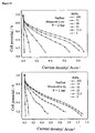
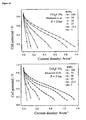
- Figure 7 shows the polarization curves for the MEA assembled from the membranes described in this example.
- Figure 12 , Figure 13 and Figure 14 show the similar polarisation curves for the MEA assembled from 5% TiO 2 F, 10% TiO 2 F and 15%. TiO 2 F membranes respectively.
- One way of evaluating the effect of relative humidity on the performance of MEA is that of using the maximum power density provided by the device under various conditions, as shown in Figure 15 , as a parameter. It can be seen how all the MEA have performances which worsen as the relative humidity of the reagents falls.
- the MEA assembled using 10% TiO 2 F membrane according to this invention is less influenced by dehydration than that assembled from pure Nafion membrane, above all if fed with pure oxygen as the oxidising agent.
Landscapes
- Chemical & Material Sciences (AREA)
- Chemical Kinetics & Catalysis (AREA)
- Engineering & Computer Science (AREA)
- Inorganic Chemistry (AREA)
- Electrochemistry (AREA)
- Manufacturing & Machinery (AREA)
- Metallurgy (AREA)
- Materials Engineering (AREA)
- Organic Chemistry (AREA)
- Sustainable Energy (AREA)
- Sustainable Development (AREA)
- General Chemical & Material Sciences (AREA)
- Life Sciences & Earth Sciences (AREA)
- Composite Materials (AREA)
- Dispersion Chemistry (AREA)
- Inorganic Compounds Of Heavy Metals (AREA)
- Fuel Cell (AREA)
- Manufacture And Refinement Of Metals (AREA)
Claims (14)
- Verwendung vor. Fluor-dotiertem kristalline Titandioxid zur Herstellung von ionenleitenden, vorzugsweise protonenleitenden anorganischen / organischen Hybridmembranen.
- Verwendung gemäß. Anspruch 1, dadurch gekennzeichnet, dass das Fluor-dotierte kristalline Titandioxid in der Form von kristallinen Titandioxidpartikeln vorliegt, welche eine durchschnittliche Partikelgröße von weniger als 500 nm und einen Fluorgehalt von zwischen 0,5 und 5 Gew.-% haben, vorzugsweise zwischen 1,0 und 4 Gew.-%.
- Verwendung gemäß Anspruch 2, dadurch gekennzeichnet, dass die Partikel eine durchschnittliche Partikelgröße von zwischen 10 und 500 nm, vorzugsweise zwischen 50 und 300 nm besitzen.
- Verwendung gemäß Anspruch 2, dadurch gekennzeichnet, dass die Artikel Hydroxylgruppen, Ammoniumkationen und Stickoxide beinhalten.
- Verwendung gemäß Anspruch 2, dadurch gekennzeichnet, dass die Partikel einen Stickstoffgehalt von zwischen 0,2 und 8 Gew.-%, vorzugsweise zwischen 0,3 und 7,5 Gew. -%, weiter vorzugsweise zwischen 2,5 und 7 Gew.-% besitzen, und / oder einen Sauerstoffgehalt von zwischen 0,05 und 4 Gew.-%, vorzugsweise zwischen 0,08 und 3 Gew.-%, weiter vorzugsweise zwischen 1,5 und 2,5 Gew.-%.
- Verwendung gemäß Anspruch 1, dadurch gekennzeichnet dass das Fluor im Wesentlichen auf den Oberflächen der Partikel vorliegt.
- Verwendung gemäß Anspruch 1, dadurch gekennzeichnet, dass mindestens 80% des Fluors, vorzugsweise mindestens 90%, in der Oberflächenschicht der Partikel vorliegt, wobei diese Oberflächenschicht eine durchschnittliche Dicke von zwischen 0, 3 und 20 non, vorzugsweise zwischen 0, 6 und 10 nm besitzt.
- Verwendung gemäß einem der Ansprüche 6 und 7, dadurch gekennzeichnet, dass Hydroxylgruppen auf der Oberfläche der Partikel vorliegen.
- Verwendung gemäß einem der vorhergehenden Ansprüche, dadurch gekennzeichnet, dass das Titandioxid in der Form von Anatase vorliegt.
- Ionenleitende, vorzugsweise protonenleitende anorganische / organische Hybridmembran, dadurch gekennzeichnet, dass sie Titandioxid gemäß einem der vorhergehenden Ansprüche enthält.
- Verwendung einer Membran gemäß Anspruch 10 zur Herstellung von Brennstoffzellen.
- Verwendung einer Membran gemäß Anspruch 10 für die Herstellung von Elektrolyseuren.
- Brennstoffzelle, welche eine Membran gemäß Anspruch 10 beinhaltet.
- Elektrolyseur, welcher eine Membran gemäß Anspruch 10 beinhaltet.
Applications Claiming Priority (2)
| Application Number | Priority Date | Filing Date | Title |
|---|---|---|---|
| ITTV2010A000115A IT1401383B1 (it) | 2010-08-06 | 2010-08-06 | Membrane ibride contenenti biossido di titanio drogato con fluoro. |
| PCT/IB2011/053261 WO2012017348A1 (en) | 2010-08-06 | 2011-07-21 | Hybrid membranes containing titanium dioxide doped with fluorine |
Publications (2)
| Publication Number | Publication Date |
|---|---|
| EP2601702A1 EP2601702A1 (de) | 2013-06-12 |
| EP2601702B1 true EP2601702B1 (de) | 2014-06-25 |
Family
ID=43629422
Family Applications (1)
| Application Number | Title | Priority Date | Filing Date |
|---|---|---|---|
| EP11761701.9A Active EP2601702B1 (de) | 2010-08-06 | 2011-07-21 | Hybridmembrane mit fluordotiertem titandioxid |
Country Status (7)
| Country | Link |
|---|---|
| US (2) | US9184460B2 (de) |
| EP (1) | EP2601702B1 (de) |
| KR (1) | KR101859543B1 (de) |
| CN (1) | CN103053059B (de) |
| ES (1) | ES2493192T3 (de) |
| IT (1) | IT1401383B1 (de) |
| WO (1) | WO2012017348A1 (de) |
Families Citing this family (17)
| Publication number | Priority date | Publication date | Assignee | Title |
|---|---|---|---|---|
| IT1401383B1 (it) * | 2010-08-06 | 2013-07-18 | Uni Degli Studi Di Padova Dip Di Scienze Chimiche | Membrane ibride contenenti biossido di titanio drogato con fluoro. |
| CN103170260B (zh) * | 2013-04-18 | 2014-09-17 | 河北麦森钛白粉有限公司 | 一种基于改性纳米二氧化钛的中空超滤膜纤维的制备工艺 |
| US9186819B1 (en) | 2014-08-19 | 2015-11-17 | Cambria Company Llc | Synthetic molded slabs, and systems and methods related thereto |
| US9289923B1 (en) | 2015-01-30 | 2016-03-22 | Cambria Company Llc | Synthetic molded slabs, and systems and methods related thereto |
| US9613412B1 (en) | 2015-12-21 | 2017-04-04 | Cambria Company Llc | Stone slab manufacturing methods and systems |
| US10467352B2 (en) | 2017-04-03 | 2019-11-05 | Cambria Company Llc | Stone slab production methods and systems |
| KR102199549B1 (ko) | 2018-03-28 | 2021-01-07 | 주식회사 엘지화학 | 분리막의 안정성 평가 방법 |
| KR102193759B1 (ko) * | 2018-09-28 | 2020-12-21 | 전남대학교산학협력단 | 유/무기고분자전해질 복합막 및 그 제조방법 |
| HUP1900214A1 (hu) * | 2019-06-14 | 2020-12-28 | Eoetvoes Lorand Tudomanyegyetem | Polipropilén- vagy polietilén-alapú szeparátor alkálifém-ferrátok elõállítására szolgáló elektrokémiai cellához |
| IT201900013734A1 (it) | 2019-08-01 | 2021-02-01 | Eni Spa | Membrana a scambio ionico con struttura a cerniera. |
| US12030260B1 (en) | 2020-01-02 | 2024-07-09 | Cambria Company Llc | Stone slabs, systems, and methods |
| RU203581U1 (ru) * | 2020-11-13 | 2021-04-13 | Федеральное государственное бюджетное образовательное учреждение высшего образования "Кубанский государственный университет" (ФГБОУ ВО "КубГУ") | Композитная катионообменная мембрана |
| WO2022241275A1 (en) | 2021-05-13 | 2022-11-17 | Cambria Company Llc | Textured stone slabs, systems, and methods |
| US12459864B2 (en) | 2021-05-13 | 2025-11-04 | Cambria Company Llc | Metallic stone slabs, systems, and methods |
| US12594689B2 (en) | 2022-11-16 | 2026-04-07 | Cambria Company Llc | Metallic stone slabs, systems, and methods |
| JP2025043917A (ja) * | 2023-09-19 | 2025-04-01 | 株式会社東芝 | 電解装置 |
| CN118983434A (zh) * | 2024-08-05 | 2024-11-19 | 青海大学 | 一种掺钛高镍层状氧化物正极材料@氟掺杂的介孔二氧化钛及制备方法 |
Family Cites Families (12)
| Publication number | Priority date | Publication date | Assignee | Title |
|---|---|---|---|---|
| US5091252A (en) * | 1984-09-17 | 1992-02-25 | Eltech Systems Corporation | Non-organic/polymer fiber composite and method of making same |
| US5597515A (en) | 1995-09-27 | 1997-01-28 | Kerr-Mcgee Corporation | Conductive, powdered fluorine-doped titanium dioxide and method of preparation |
| US7098163B2 (en) | 1998-08-27 | 2006-08-29 | Cabot Corporation | Method of producing membrane electrode assemblies for use in proton exchange membrane and direct methanol fuel cells |
| DE10246372A1 (de) | 2002-10-04 | 2004-04-15 | Celanese Ventures Gmbh | Mit einer Katalysatorschicht beschichtete protonenleitende Polymermembran enthaltend Polyazole und deren Anwendung in Brennstoffzellen |
| RU2255900C1 (ru) | 2004-03-22 | 2005-07-10 | Гордиенко Павел Сергеевич | Реакторная установка |
| JP2006032135A (ja) | 2004-07-16 | 2006-02-02 | Toyota Motor Corp | 固体高分子電解質膜の製造方法、固体高分子電解質膜、およびこれを備える燃料電池 |
| EP1683762A1 (de) * | 2005-01-24 | 2006-07-26 | BRETON s.p.a. | Verfahren zur Herstellung von Titandioxid unter Verwendung von wässrigem Ammoniumfluorid |
| JP2009518264A (ja) * | 2005-12-01 | 2009-05-07 | ザ リージェンツ オブ ザ ユニバーシティ オブ カリフォルニア | イオン伝導用の機能化された無機薄膜 |
| CN101359743A (zh) | 2007-08-03 | 2009-02-04 | 江苏新源动力有限公司 | 无机/有机复合质子燃料电池交换膜及制备方法 |
| GB0804365D0 (en) | 2008-03-10 | 2008-04-16 | Dublin Inst Of Technology | Synthesis of nanoporous semi-conducting oxides |
| IT1402230B1 (it) * | 2010-08-06 | 2013-08-28 | Breton Spa | Biossido di titanio drogato con fluoro e suo processo di produzione. |
| IT1401383B1 (it) * | 2010-08-06 | 2013-07-18 | Uni Degli Studi Di Padova Dip Di Scienze Chimiche | Membrane ibride contenenti biossido di titanio drogato con fluoro. |
-
2010
- 2010-08-06 IT ITTV2010A000115A patent/IT1401383B1/it active
-
2011
- 2011-07-21 US US13/814,353 patent/US9184460B2/en active Active
- 2011-07-21 EP EP11761701.9A patent/EP2601702B1/de active Active
- 2011-07-21 CN CN201180038185.XA patent/CN103053059B/zh active Active
- 2011-07-21 KR KR1020137005853A patent/KR101859543B1/ko active Active
- 2011-07-21 WO PCT/IB2011/053261 patent/WO2012017348A1/en not_active Ceased
- 2011-07-21 ES ES11761701.9T patent/ES2493192T3/es active Active
-
2015
- 2015-09-29 US US14/868,953 patent/US9577278B2/en active Active
Also Published As
| Publication number | Publication date |
|---|---|
| ES2493192T3 (es) | 2014-09-11 |
| ITTV20100115A1 (it) | 2012-02-07 |
| US9577278B2 (en) | 2017-02-21 |
| CN103053059A (zh) | 2013-04-17 |
| KR20130098329A (ko) | 2013-09-04 |
| US20130196251A1 (en) | 2013-08-01 |
| KR101859543B1 (ko) | 2018-05-18 |
| EP2601702A1 (de) | 2013-06-12 |
| CN103053059B (zh) | 2019-04-12 |
| WO2012017348A1 (en) | 2012-02-09 |
| IT1401383B1 (it) | 2013-07-18 |
| US9184460B2 (en) | 2015-11-10 |
| US20160087302A1 (en) | 2016-03-24 |
Similar Documents
| Publication | Publication Date | Title |
|---|---|---|
| US9577278B2 (en) | Hybrid membranes containing titanium dioxide doped with fluorine | |
| EP2601139B1 (de) | Mit fluor dotiertes titandioxid und verfahren zu seiner herstellung | |
| Di Vona et al. | Composite polymer electrolytes of sulfonated poly-ether-ether-ketone (SPEEK) with organically functionalized TiO2 | |
| EP1511112A1 (de) | Polymer Nanocompositmembran und Brennstoffzell diese enthaltend | |
| Salarizadeh et al. | Enhanced properties of SPEEK with incorporating of PFSA and barium strontium titanate nanoparticles for application in DMFCs | |
| Kim et al. | Fenton stability of mesoporous ceria–silica and its role in enhanced durability of poly (arylene ether sulfone) multiblock copolymer composite membranes for perfluorosulfonic acid alternatives | |
| JP5755346B2 (ja) | 燃料電池用電極触媒層、膜電極接合体及び固体高分子型燃料電池。 | |
| KR102715521B1 (ko) | 라디칼 스케빈저의 작용을 가지는 금속산화물-산화그래핀 나노복합체 입자 및 이의 제조 방법, 이를 이용한 음이온교환막 및 연료전지 | |
| KR100496936B1 (ko) | 양성자 전도성 고분자 막, 이의 제조방법, 이를 이용한막-전극 어셈블리 및 이를 포함하는 연료전지 | |
| KR102081767B1 (ko) | 중공 실리카를 포함하는 바나듐 레독스 플로우 배터리용 전해액 및 이를 포함하는 바나듐 레독스 플로우 배터리 | |
| JP2026506289A (ja) | SiO2に担持されたラジカル捕捉剤としてのCeO2 | |
| KR102602488B1 (ko) | 쯔비터이온을 포함하는 작용기화된 산화흑연 기반의 음이온 유무기 복합 전해질막 및 이의 제조방법 | |
| Li et al. | Enhanced proton conductivity of polymer electrolyte membrane doped with titanate nanotubes | |
| KR102797248B1 (ko) | 라디칼 스케빈저의 작용을 가지는 금속산화물-아이오노머 나노복합체 입자를 포함하는 음이온교환막 제조용 조성물, 이를 이용한 음이온교환막 및 연료전지 | |
| JP2006291065A (ja) | 高分子組成物およびそれからなる高分子フィルム並びに高分子電解質膜 | |
| Çelik et al. | The Evaluation of Potential Usage of Ti | |
| Song et al. | Self-assembly of α-MnO2 nanorods into spheres: Synthesis and electrochemical properties | |
| WO2025133363A1 (en) | Compositions comprising cerium oxide/polyoxometalate particles and ion exchange polymer, and their use in proton exchange membranes or electrocatalyst layers | |
| KR20230157005A (ko) | 고분자전해질형연료전지에 무기나노입자가 함침된 새로운 고분자막 제조기술 | |
| CN117543035A (zh) | 一种Nafion-C/CeO2/Pt复合膜及其制备方法和应用 | |
| LUISA DI VONA et al. | COMPOSITE MEMBRANES BASED ON SPEEK FOR POLYMER ELECTROLYTE MEMBRANE FUEL CELLS | |
| Treekamol | Development of polymer composite membranes with functionalized nanoparticles for fuel cell application |
Legal Events
| Date | Code | Title | Description |
|---|---|---|---|
| PUAI | Public reference made under article 153(3) epc to a published international application that has entered the european phase |
Free format text: ORIGINAL CODE: 0009012 |
|
| 17P | Request for examination filed |
Effective date: 20130201 |
|
| AK | Designated contracting states |
Kind code of ref document: A1 Designated state(s): AL AT BE BG CH CY CZ DE DK EE ES FI FR GB GR HR HU IE IS IT LI LT LU LV MC MK MT NL NO PL PT RO RS SE SI SK SM TR |
|
| DAX | Request for extension of the european patent (deleted) | ||
| GRAP | Despatch of communication of intention to grant a patent |
Free format text: ORIGINAL CODE: EPIDOSNIGR1 |
|
| INTG | Intention to grant announced |
Effective date: 20140129 |
|
| GRAP | Despatch of communication of intention to grant a patent |
Free format text: ORIGINAL CODE: EPIDOSNIGR1 |
|
| INTG | Intention to grant announced |
Effective date: 20140401 |
|
| GRAS | Grant fee paid |
Free format text: ORIGINAL CODE: EPIDOSNIGR3 |
|
| GRAA | (expected) grant |
Free format text: ORIGINAL CODE: 0009210 |
|
| AK | Designated contracting states |
Kind code of ref document: B1 Designated state(s): AL AT BE BG CH CY CZ DE DK EE ES FI FR GB GR HR HU IE IS IT LI LT LU LV MC MK MT NL NO PL PT RO RS SE SI SK SM TR |
|
| REG | Reference to a national code |
Ref country code: GB Ref legal event code: FG4D |
|
| REG | Reference to a national code |
Ref country code: CH Ref legal event code: EP |
|
| REG | Reference to a national code |
Ref country code: AT Ref legal event code: REF Ref document number: 675172 Country of ref document: AT Kind code of ref document: T Effective date: 20140715 |
|
| REG | Reference to a national code |
Ref country code: IE Ref legal event code: FG4D |
|
| REG | Reference to a national code |
Ref country code: DE Ref legal event code: R096 Ref document number: 602011008016 Country of ref document: DE Effective date: 20140807 |
|
| REG | Reference to a national code |
Ref country code: ES Ref legal event code: FG2A Ref document number: 2493192 Country of ref document: ES Kind code of ref document: T3 Effective date: 20140911 |
|
| PG25 | Lapsed in a contracting state [announced via postgrant information from national office to epo] |
Ref country code: CY Free format text: LAPSE BECAUSE OF FAILURE TO SUBMIT A TRANSLATION OF THE DESCRIPTION OR TO PAY THE FEE WITHIN THE PRESCRIBED TIME-LIMIT Effective date: 20140625 Ref country code: GR Free format text: LAPSE BECAUSE OF FAILURE TO SUBMIT A TRANSLATION OF THE DESCRIPTION OR TO PAY THE FEE WITHIN THE PRESCRIBED TIME-LIMIT Effective date: 20140926 Ref country code: NO Free format text: LAPSE BECAUSE OF FAILURE TO SUBMIT A TRANSLATION OF THE DESCRIPTION OR TO PAY THE FEE WITHIN THE PRESCRIBED TIME-LIMIT Effective date: 20140925 Ref country code: LT Free format text: LAPSE BECAUSE OF FAILURE TO SUBMIT A TRANSLATION OF THE DESCRIPTION OR TO PAY THE FEE WITHIN THE PRESCRIBED TIME-LIMIT Effective date: 20140625 Ref country code: FI Free format text: LAPSE BECAUSE OF FAILURE TO SUBMIT A TRANSLATION OF THE DESCRIPTION OR TO PAY THE FEE WITHIN THE PRESCRIBED TIME-LIMIT Effective date: 20140625 |
|
| REG | Reference to a national code |
Ref country code: AT Ref legal event code: MK05 Ref document number: 675172 Country of ref document: AT Kind code of ref document: T Effective date: 20140625 |
|
| REG | Reference to a national code |
Ref country code: NL Ref legal event code: VDEP Effective date: 20140625 |
|
| REG | Reference to a national code |
Ref country code: LT Ref legal event code: MG4D |
|
| PG25 | Lapsed in a contracting state [announced via postgrant information from national office to epo] |
Ref country code: HR Free format text: LAPSE BECAUSE OF FAILURE TO SUBMIT A TRANSLATION OF THE DESCRIPTION OR TO PAY THE FEE WITHIN THE PRESCRIBED TIME-LIMIT Effective date: 20140625 Ref country code: LV Free format text: LAPSE BECAUSE OF FAILURE TO SUBMIT A TRANSLATION OF THE DESCRIPTION OR TO PAY THE FEE WITHIN THE PRESCRIBED TIME-LIMIT Effective date: 20140625 Ref country code: RS Free format text: LAPSE BECAUSE OF FAILURE TO SUBMIT A TRANSLATION OF THE DESCRIPTION OR TO PAY THE FEE WITHIN THE PRESCRIBED TIME-LIMIT Effective date: 20140625 Ref country code: SE Free format text: LAPSE BECAUSE OF FAILURE TO SUBMIT A TRANSLATION OF THE DESCRIPTION OR TO PAY THE FEE WITHIN THE PRESCRIBED TIME-LIMIT Effective date: 20140625 |
|
| PG25 | Lapsed in a contracting state [announced via postgrant information from national office to epo] |
Ref country code: EE Free format text: LAPSE BECAUSE OF FAILURE TO SUBMIT A TRANSLATION OF THE DESCRIPTION OR TO PAY THE FEE WITHIN THE PRESCRIBED TIME-LIMIT Effective date: 20140625 Ref country code: SK Free format text: LAPSE BECAUSE OF FAILURE TO SUBMIT A TRANSLATION OF THE DESCRIPTION OR TO PAY THE FEE WITHIN THE PRESCRIBED TIME-LIMIT Effective date: 20140625 Ref country code: PT Free format text: LAPSE BECAUSE OF FAILURE TO SUBMIT A TRANSLATION OF THE DESCRIPTION OR TO PAY THE FEE WITHIN THE PRESCRIBED TIME-LIMIT Effective date: 20141027 Ref country code: CZ Free format text: LAPSE BECAUSE OF FAILURE TO SUBMIT A TRANSLATION OF THE DESCRIPTION OR TO PAY THE FEE WITHIN THE PRESCRIBED TIME-LIMIT Effective date: 20140625 Ref country code: RO Free format text: LAPSE BECAUSE OF FAILURE TO SUBMIT A TRANSLATION OF THE DESCRIPTION OR TO PAY THE FEE WITHIN THE PRESCRIBED TIME-LIMIT Effective date: 20140625 |
|
| PG25 | Lapsed in a contracting state [announced via postgrant information from national office to epo] |
Ref country code: NL Free format text: LAPSE BECAUSE OF FAILURE TO SUBMIT A TRANSLATION OF THE DESCRIPTION OR TO PAY THE FEE WITHIN THE PRESCRIBED TIME-LIMIT Effective date: 20140625 Ref country code: PL Free format text: LAPSE BECAUSE OF FAILURE TO SUBMIT A TRANSLATION OF THE DESCRIPTION OR TO PAY THE FEE WITHIN THE PRESCRIBED TIME-LIMIT Effective date: 20140625 Ref country code: IS Free format text: LAPSE BECAUSE OF FAILURE TO SUBMIT A TRANSLATION OF THE DESCRIPTION OR TO PAY THE FEE WITHIN THE PRESCRIBED TIME-LIMIT Effective date: 20141025 Ref country code: AT Free format text: LAPSE BECAUSE OF FAILURE TO SUBMIT A TRANSLATION OF THE DESCRIPTION OR TO PAY THE FEE WITHIN THE PRESCRIBED TIME-LIMIT Effective date: 20140625 |
|
| REG | Reference to a national code |
Ref country code: CH Ref legal event code: PL |
|
| REG | Reference to a national code |
Ref country code: DE Ref legal event code: R097 Ref document number: 602011008016 Country of ref document: DE |
|
| PG25 | Lapsed in a contracting state [announced via postgrant information from national office to epo] |
Ref country code: MC Free format text: LAPSE BECAUSE OF FAILURE TO SUBMIT A TRANSLATION OF THE DESCRIPTION OR TO PAY THE FEE WITHIN THE PRESCRIBED TIME-LIMIT Effective date: 20140625 |
|
| REG | Reference to a national code |
Ref country code: IE Ref legal event code: MM4A |
|
| PG25 | Lapsed in a contracting state [announced via postgrant information from national office to epo] |
Ref country code: LI Free format text: LAPSE BECAUSE OF NON-PAYMENT OF DUE FEES Effective date: 20140731 Ref country code: CH Free format text: LAPSE BECAUSE OF NON-PAYMENT OF DUE FEES Effective date: 20140731 Ref country code: DK Free format text: LAPSE BECAUSE OF FAILURE TO SUBMIT A TRANSLATION OF THE DESCRIPTION OR TO PAY THE FEE WITHIN THE PRESCRIBED TIME-LIMIT Effective date: 20140625 |
|
| PLBE | No opposition filed within time limit |
Free format text: ORIGINAL CODE: 0009261 |
|
| STAA | Information on the status of an ep patent application or granted ep patent |
Free format text: STATUS: NO OPPOSITION FILED WITHIN TIME LIMIT |
|
| 26N | No opposition filed |
Effective date: 20150326 |
|
| PG25 | Lapsed in a contracting state [announced via postgrant information from national office to epo] |
Ref country code: BE Free format text: LAPSE BECAUSE OF FAILURE TO SUBMIT A TRANSLATION OF THE DESCRIPTION OR TO PAY THE FEE WITHIN THE PRESCRIBED TIME-LIMIT Effective date: 20140625 |
|
| PG25 | Lapsed in a contracting state [announced via postgrant information from national office to epo] |
Ref country code: IE Free format text: LAPSE BECAUSE OF NON-PAYMENT OF DUE FEES Effective date: 20140721 |
|
| PG25 | Lapsed in a contracting state [announced via postgrant information from national office to epo] |
Ref country code: SI Free format text: LAPSE BECAUSE OF FAILURE TO SUBMIT A TRANSLATION OF THE DESCRIPTION OR TO PAY THE FEE WITHIN THE PRESCRIBED TIME-LIMIT Effective date: 20140625 |
|
| PG25 | Lapsed in a contracting state [announced via postgrant information from national office to epo] |
Ref country code: SM Free format text: LAPSE BECAUSE OF FAILURE TO SUBMIT A TRANSLATION OF THE DESCRIPTION OR TO PAY THE FEE WITHIN THE PRESCRIBED TIME-LIMIT Effective date: 20140625 |
|
| REG | Reference to a national code |
Ref country code: FR Ref legal event code: PLFP Year of fee payment: 6 |
|
| PG25 | Lapsed in a contracting state [announced via postgrant information from national office to epo] |
Ref country code: MT Free format text: LAPSE BECAUSE OF FAILURE TO SUBMIT A TRANSLATION OF THE DESCRIPTION OR TO PAY THE FEE WITHIN THE PRESCRIBED TIME-LIMIT Effective date: 20140625 Ref country code: BG Free format text: LAPSE BECAUSE OF FAILURE TO SUBMIT A TRANSLATION OF THE DESCRIPTION OR TO PAY THE FEE WITHIN THE PRESCRIBED TIME-LIMIT Effective date: 20140625 |
|
| PG25 | Lapsed in a contracting state [announced via postgrant information from national office to epo] |
Ref country code: HU Free format text: LAPSE BECAUSE OF FAILURE TO SUBMIT A TRANSLATION OF THE DESCRIPTION OR TO PAY THE FEE WITHIN THE PRESCRIBED TIME-LIMIT; INVALID AB INITIO Effective date: 20110721 Ref country code: LU Free format text: LAPSE BECAUSE OF NON-PAYMENT OF DUE FEES Effective date: 20140721 |
|
| REG | Reference to a national code |
Ref country code: FR Ref legal event code: PLFP Year of fee payment: 7 |
|
| REG | Reference to a national code |
Ref country code: FR Ref legal event code: PLFP Year of fee payment: 8 |
|
| PG25 | Lapsed in a contracting state [announced via postgrant information from national office to epo] |
Ref country code: MK Free format text: LAPSE BECAUSE OF FAILURE TO SUBMIT A TRANSLATION OF THE DESCRIPTION OR TO PAY THE FEE WITHIN THE PRESCRIBED TIME-LIMIT Effective date: 20140625 |
|
| PGFP | Annual fee paid to national office [announced via postgrant information from national office to epo] |
Ref country code: TR Payment date: 20180529 Year of fee payment: 14 |
|
| PG25 | Lapsed in a contracting state [announced via postgrant information from national office to epo] |
Ref country code: AL Free format text: LAPSE BECAUSE OF FAILURE TO SUBMIT A TRANSLATION OF THE DESCRIPTION OR TO PAY THE FEE WITHIN THE PRESCRIBED TIME-LIMIT Effective date: 20140625 |
|
| PGFP | Annual fee paid to national office [announced via postgrant information from national office to epo] |
Ref country code: ES Payment date: 20180801 Year of fee payment: 8 |
|
| GBPC | Gb: european patent ceased through non-payment of renewal fee |
Effective date: 20190721 |
|
| PG25 | Lapsed in a contracting state [announced via postgrant information from national office to epo] |
Ref country code: GB Free format text: LAPSE BECAUSE OF NON-PAYMENT OF DUE FEES Effective date: 20190721 |
|
| REG | Reference to a national code |
Ref country code: ES Ref legal event code: FD2A Effective date: 20201130 |
|
| PG25 | Lapsed in a contracting state [announced via postgrant information from national office to epo] |
Ref country code: ES Free format text: LAPSE BECAUSE OF NON-PAYMENT OF DUE FEES Effective date: 20190722 |
|
| P01 | Opt-out of the competence of the unified patent court (upc) registered |
Effective date: 20230624 |
|
| PG25 | Lapsed in a contracting state [announced via postgrant information from national office to epo] |
Ref country code: TR Free format text: LAPSE BECAUSE OF NON-PAYMENT OF DUE FEES Effective date: 20190721 |
|
| PGFP | Annual fee paid to national office [announced via postgrant information from national office to epo] |
Ref country code: FR Payment date: 20250620 Year of fee payment: 15 |
|
| PGFP | Annual fee paid to national office [announced via postgrant information from national office to epo] |
Ref country code: DE Payment date: 20250620 Year of fee payment: 15 |
|
| PGFP | Annual fee paid to national office [announced via postgrant information from national office to epo] |
Ref country code: IT Payment date: 20250619 Year of fee payment: 15 |